

Page 1
RCH-20
JOTRON electronics a.s.
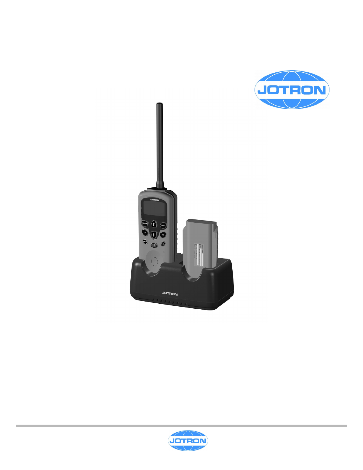
RCH-20
Charger for Tron TR20 GMDSS /PLUS
Technical Handbook
Dec.2001
Page 2
RCH-20
AMENDMENT RECORD
AMDT INCORP. BY DATE PAGE(S) AMDT INCORP. BY DATE PAGE(S)
1
21
2
22
3
23
4
24
5
25
6
26
7
27
8
28
9
29
10
30
11
31
12
32
13
33
14
34
15
35
16
36
17
37
18
38
19
39
20
40
Page 3

RCH-20
The information in this book has been carefully checked and is believed to be
accurate. However, no responsibility is assumed for inaccuracies.
CAUTION!
This equipment contains CMOS integrated circuits. Observe handling precautions to
avoid static discharges which may damage these devices.
JOTRON electronics a.s reserves the right to make changes without further notice
to any products or modules described herein to improve reliability, function or design.
JOTRON electronic a.s does not assume any liability arising
out of the application or use of the described product.
Page 4

RCH-20
CONTENTS
-----------------------------------------------------------------------------------------------------------------
1. SYSTEM DESCRIPTION...........................................................................................................1-1
General information ...........................................................................................................................1-1
2. TECHNICAL SPECIFICATION ..................................................................................................2-1
3. FUNCTIONAL DESCRIPTION ..................................................................................................3-1
Precautions and Warnings ................................................................................................................3-1
Batteries........................................................................................................................................................3-1
Connectors and cables..................................................................................................................................3-1
Storage and safe handling............................................................................................................................. 3-1
4. OPERATING INSTRUCTIONS.................................................................................................. 4-1
Operation...........................................................................................................................................4-1
Notes on charging .............................................................................................................................4-1
5. TECHNICAL DESCRIPTION .....................................................................................................5-1
Introduction........................................................................................................................................ 5-1
Main board (80011) ...........................................................................................................................5-1
6. MAINTENANCE .........................................................................................................................6-1
7. DIAGRAMS ................................................................................................................................7-1
8. PARTS LISTS ............................................................................................................................8-1
Page 5

RCH-20 1-1
1. SYSTEM DESCRIPTION
General information
RCH-20 is designed to charge the NiMH battery pack for the Tron TR20 GMDSS and Tron TR20
PLUS handheld VHF radios.
It is a dual slot intelligent rapid charger with microprocessor control.
It will fully charge an empty battery pack in less than 4 hours.
It is designed to operate from 12 –24 VDC or 115 / 230VAC with an external adapter.
It is equipped with mounting holes for wall mounting or mounting on a table or shelf.
Page 6

RCH-20
2-1
2. TECHNICAL SPECIFICATION
General
Dual slot rapid charger with trickle charging.
Wall and table mountable.
Operating voltage: 12 - 24VDC (30VDC max)
115/230VAC with external mains adapter.
Current consumption: < 600mA @12VDC
Charging current: 450 – 500mA (Rapid charge)
Trickle charge approx 10mA
Charge termination method: ∆V, ∆t and timeout.
Charging time: < 4 hours on a fully discharged NiMH battery (X-80059)
Operating temperature range: 0 to +40°C.
Size: 155mm wide x 69mm height x 83mm depth
Weight : Approx. 300g
Page 7

RCH-20
3-1
3. FUNCTIONAL DESCRIPTION
Precautions and Warnings
Batteries
The rechargeable battery is of NiMH type with a capacity of 7.2V/1500mAh. The following
should be noticed:
• Do not short-circuit, solder, crush, disassemble or incinerate the battery pack. This may
result in fire, explosion and severe burn hazard.
• Avoid charging batteries below 0 °C or above 40 °C.
Connectors and cables
When handling connectors and cables, notice the following warnings:
• Do not force plugs in place, as this may damage the pins in the plugs.
Storage and safe handling
Storage temperature range is from –30°C to +70°C and operating temperature is from 0 °C to
+40 °C.
Cleaning of the equipment can be done with a cloth soaked in a mixture of ordinary dishdetergent and water.
Page 8

RCH-20
4-1
4. OPERATING INSTRUCTIONS
Operation
The charger RCH-20 is a dual slot quick charger. The charger will accept a complete radio or the
battery alone (see fig 4). If two batteries are present, the charger will automatically start fast charging
the second battery when the first battery is fully charged. The first battery will then be trickle charged
to keep it fully charged.
Fig. 1
The charger operates from 12 – 24 VDC or from 115 / 230 VAC using an appropriate adapter.
When using DC supply, the DC cable (80084) should be used. The connector is a standard 5.5mm AC
adaptor type.
To prevent problems with wrong polarity the RCH-20 is designed to be independent of the power
supply polarity.
The charger has two LED indicators, one for each battery. They have the following functions:
Flashing orange - No battery detected
Flashing red - Battery detected, trickle charging
Continuous red - Fast charging
Continuous green - Battery fully charged, trickle charging
Notes on charging
The battery pack, 80059, is of NiMH type. To get the most out of your battery pack, a few precautions
should be taken.
• Always charge the battery to full charge when charging.
Page 9

RCH-20
4-2
• All rechargeable batteries lose charge while stored. The rate is dependent on the temperature.
When stored at 25°C a fully charged battery will have more than 50% capacity after a few
months, while at 45°C it might be down at 50% after approx one month.
• Although it is possible to charge the battery while the Tron TR20 is switched on it is
recommended to charge with the radio switched off. Otherwise the current consumption of the
radio may confuse the charger to terminate before full charge is reached.
• If the battery has been totally discharged (below the Tron TR20 switch off threshold), or stored for
a long time, the charger may terminate before full charge is reached.
In this case do as follows:
o Insert the battery and charge for a few minutes.
o Discharge the battery by inserting it into the radio, and press PTT a few times.
o Start charging.
• Never short-circuit, solder, reverse charge, crush, disassemble or incinerate. This may result in
fire, explosion and severe burn hazard.
• Avoid charging under 0
o
C or over 40oC.
Page 10

RCH-20
5-1
5. TECHNICAL DESCRIPTION
Introduction
The Charger consists of 1 printed circuit board.
• Main board (80011)
Main board (80011)
The charger can be divided into following functional blocks:
• Switch mode regulator
• Current measurement circuit
• Voltage measurement circuit
• Temperature measurement circuit
• Charge control circuits
Switch mode regulator
The supply voltage is supplied trough the bridge rectifier D5, to make the charger independent of
supply polarity.
The microcontroller (IC1) with software controls all functions in the charger, including the switch mode
regulator. The microcontroller operates on 5V, supplied from voltage regulator (IC3).
The switch mode regulator delivers the charging current to the batteries. The switching transistor (Q2
or Q1) is controlled by the PWM (Pulse Width Modulator) output of the microcontroller. The pulse
width is adjusted according to the reading from the current measurement circuit.
Current measurement circuit
The current flowing through the batteries will generate a voltage across the resistors R32 – R36. This
voltage is amplified by IC2A, and fed to one of the A/D inputs of IC1. The reading from this A/D input is
used to correct the duty cycle of the PWM output, and hence adjust the charging current.
Voltage measurement circuit
IC2B and IC2C are used as voltage amplifiers. The offset voltage, supplied from IC2D, is used to give
the amplifiers a 0 – 5V output, which is feed to one of the A/D inputs of the microcontroller, IC1. The
voltage is used by the microcontroller to detect the ∆V slope which is used for charging termination.
The voltage is measured every 120 second, and compared with the previous reading. A negative or no
change will terminate the charging.
I addition a voltage above approx. 9.7 V will terminate the charging as well.
Temperature measurement circuit
The NiMH batteries contain a 2.2kohm NTC which is used to measure the temperature of the battery.
R15 and R16 act as pull up resistors for the NTC. R30 and 31 is for future use with batteries with
different chemistry and a different NTC value.
The voltage from the NTC is fed to one of the A/D inputs of IC1. The reading from this A/D input is
used to detect a temperature rise in the batteries, which again will make the charger terminate
charging.
Page 11

RCH-20
5-2
Charge control circuits
Each battery position has a separate switch to select charging. Q3 and Q7 are used to switch charging
on and off, and are controlled by output ports on IC1, to select which battery is going to be charged.
In addition to the voltage and temperature reading, an internal timer is used to terminate the charging
if no other termination occurs within approx 4.5 hours.
When there is no battery, or a fully charge battery is placed in the slot, the charger will send short
charging pulses to each slot. This is used to detect whether a battery is present in each slot, as well as
supplying trickle charge to fully charged batteries. The trickle charge is approx 10mA on average.
Status of the charging is indicated by D1 and D2, which are bicolour LED’s. The function of these
diodes is explained in chapter 4.
Page 12

RCH-20
6-1
6. MAINTENANCE
No maintenance is necessary.
Page 13

RCH-20
7-1
7. DIAGRAMS
Circuit diagram, Main board E-80011
Place plan, Main board, part 1 KP-80011-1/2
Place plan, Main board, part 2 KP-80011-2/2
NOTE! The place plan drawings show the maximum configuration for a printed circuit board. For
components actually fitted on a printed circuit board, please refer to the parts list for that board.
Page 14

Page 15

Page 16

Page 17

RCH-20
8-1
8. PARTS LISTS
• Part list, Complete Charger BOM-99920
• Part list, Main Board BOM-80011
Page 18

Bill Of Material
Item
Version
Date
7.12.2001
99920 BATTERY CHARGER 12/24VDC FOR Tron
T
Manufacturing
JOTRON electronics a.s.
Item Name / Description Makes no. / Additional name Sub pos.
80011 Electronic unit, RCH-20
1
80084 DC CABLE FOR RCH-20
10
80357 LABEL FOR PACKINGBOX LADER
TR-20 11
80061 Etikett til RCH-20 batteri lader
Fascal 805, Orange/Sort txt 2
99886 BATTERILADER - BUNNDEL
Cycoloy C2100 HF Sort 3
99887 Spring, 3.0 x 2.4 x10mm, BeCu
4
99888 KONTAKTPINNE I LADER
RCH-20 5
99889 LYSLEDER I LADER
RCH-20 6
99916 Hjelpesnepp lader
Cycoloy C2100 HF Sort 7
99883 BATTERILADER, TOPPDEL
Cycoloy C2100 HF Sort 8
99890 PT.SCREW SENKH. KB30X30
EJOT-PT KB30x30 WN 1452 9
Page 19

Bill Of Material
Item
Version
Page 1 of 2
Date
7.12.2001
80011 Electronic unit, RCH-20 Design
JOTRON electronics a.s.
Item Name / Description Makes no. / Additional name Sub pos.
99123 CAP.EL 330uF/25V 10X10 SMD
ELNA RVH25V331MVH-10-R
C001
99123 CAP.EL 330uF/25V 10X10 SMD
ELNA RVH25V331MVH-10-R
C002
93225 CHIP CAP 100nF 50V X7R 10% - 0805
MURATA GRM40 X7R 104 K50
C003
93225 CHIP CAP 100nF 50V X7R 10% - 0805
MURATA GRM40 X7R 104 K50
C004
OMIT Utgår
C005
OMIT Utgår
C006
93225 CHIP CAP 100nF 50V X7R 10% - 0805
MURATA GRM40 X7R 104 K50
C007
99123 CAP.EL 330uF/25V 10X10 SMD
ELNA RVH25V331MVH-10-R
C008
93225 CHIP CAP 100nF 50V X7R 10% - 0805
MURATA GRM40 X7R 104 K50
C009
93225 CHIP CAP 100nF 50V X7R 10% - 0805
MURATA GRM40 X7R 104 K50
C010
93225 CHIP CAP 100nF 50V X7R 10% - 0805
MURATA GRM40 X7R 104 K50
C011
80031 LED SMD bicolor Red/Green, HSMF-C155
HP HSMF-C155
D001
80031 LED SMD bicolor Red/Green, HSMF-C155
HP HSMF-C155
D002
94704 DIODE ,Schottky, smd, 3A ,MBRS340T3
Motorola MBRS340T3
D003
94704 DIODE ,Schottky, smd, 3A ,MBRS340T3
Motorola MBRS340T3
D004
96655 BRIDGE RECTIFIER
Micro El. WO-005G
D005
94704 DIODE ,Schottky, smd, 3A ,MBRS340T3
Motorola MBRS340T3
D006
94704 DIODE ,Schottky, smd, 3A ,MBRS340T3
Motorola MBRS340T3
D007
80055 PIC16F73-I/SO
Microchip PIC 16F73-I/SO
IC001
99262 TS914, Quad R/R CMOS OpAmp
2.7-16Volt, SO14, -40 to +125°C IC002
99644 Voltage regulator 5 V , SOT223
National LM340MP-5.0
IC003
80032 DC Power Jack Ø=5.5, ø= 2.0 mm, LD-0202
Lih Sheng LD-0202
J001
99807 TERM. STRIP, 2,54mm, 2x3pin, l=11mm
Samtec TSW103-07TD
J002
99124 INDUCTOR POWER 100uH/1.2A SMD
PULSE P0752.104T
L001
99124 INDUCTOR POWER 100uH/1.2A SMD
PULSE P0752.104T
L002
99892 PCB I LADER
TRON VHF MkII PCB
OMIT Utgår
Q001
97787 P-FET, SOT-223
Siemens BSP315 Q002
99762 SI2307, P-MFET,30V, 80mOhm@10V, SOT-23
Siliconix SI2307DS
Q003
94443 TRANSISTOR BC 817 SOT-23
PHILIPS BC817,215
Q004
94443 TRANSISTOR BC 817 SOT-23
PHILIPS BC817,215
Q005
94443 TRANSISTOR BC 817 SOT-23
PHILIPS BC817,215
Q006
99762 SI2307, P-MFET,30V, 80mOhm@10V, SOT-23
Siliconix SI2307DS
Q007
93280 CR 0805 10k 1%
ROHM MCR10 EZH F-1002
R001
93284 CR 0805 15k 1%
ROHM MCR10 EZH F-1502
R002
93256 CR 0805 1k0 1%
ROHM MCR10 EZH F-1001
R003
93272 CR 0805 4k7 1%
ROHM MCR10 EZH F-4701
R004
93244 CR 0805 330R 1%
ROHM MCR10 EZH F-3300
R005
93244 CR 0805 330R 1%
ROHM MCR10 EZH F-3300
R006
93244 CR 0805 330R 1%
ROHM MCR10 EZH F-3300
R007
93244 CR 0805 330R 1%
ROHM MCR10 EZH F-3300
R008
93290 CR 0805 27k 1%
ROHM MCR10 EZH F-2702
R009
93256 CR 0805 1k0 1%
ROHM MCR10 EZH F-1001
R010
93294 CR 0805 39k 1%
ROHM MCR10 EZH F-3902
R011
93284 CR 0805 15k 1%
ROHM MCR10 EZH F-1502
R012
Page 20

Bill Of Material
Item
Version
Page 2 of 2
Date
7.12.2001
80011 Electronic unit, RCH-20 Design
JOTRON electronics a.s.
Item Name / Description Makes no. / Additional name Sub pos.
OMIT Utgår
R013
93290 CR 0805 27k 1%
ROHM MCR10 EZH F-2702
R014
93264 CR 0805 2k2 1%
ROHM MCR10 EZH F-2201
R015
93264 CR 0805 2k2 1%
ROHM MCR10 EZH F-2201
R016
93287 CR 0805 20k 1%
ROHM MCR10 EZH F-2002
R017
93280 CR 0805 10k 1%
ROHM MCR10 EZH F-1002
R018
93287 CR 0805 20k 1%
ROHM MCR10 EZH F-2002
R019
93280 CR 0805 10k 1%
ROHM MCR10 EZH F-1002
R020
93294 CR 0805 39k 1%
ROHM MCR10 EZH F-3902
R021
93284 CR 0805 15k 1%
ROHM MCR10 EZH F-1502
R022
93292 CR 0805 33k 1%
ROHM MCR10 EZH F-3302
R023
93280 CR 0805 10k 1%
ROHM MCR10 EZH F-1002
R024
93280 CR 0805 10k 1%
ROHM MCR10 EZH F-1002
R025
93280 CR 0805 10k 1%
ROHM MCR10 EZH F-1002
R026
93280 CR 0805 10k 1%
ROHM MCR10 EZH F-1002
R027
93280 CR 0805 10k 1%
ROHM MCR10 EZH F-1002
R028
93280 CR 0805 10k 1%
ROHM MCR10 EZH F-1002
R029
93304 CR 0805 100k 1%
ROHM MCR10 EZH F-1003
R030
93304 CR 0805 100k 1%
ROHM MCR10 EZH F-1003
R031
97180 RC-01 1R
PHILIPS 2322 711 61108
R032
97180 RC-01 1R
PHILIPS 2322 711 61108
R033
97180 RC-01 1R
PHILIPS 2322 711 61108
R034
97180 RC-01 1R
PHILIPS 2322 711 61108
R035
97180 RC-01 1R
PHILIPS 2322 711 61108
R036
80052 10 MHz Ceramic resonator
MURATA CSTCC 10.00MHZ MG
X001
Page 21

RCH-20
CONTACT JOTRON:
JOTRON electronics a.s.
P.O. box 54
N-3280 Tjodalyng
NORWAY
Telephone (switchboard): +47 33 13 97 00
Fax: +47 33 12 67 80
Email: salesair@jotron.com
WWW: http://www.jotron.com
 Loading...