

Page 1

82693_Op&Ins MAN_TR2500_D 1
Page 2

82694_Op&Ins MAN_RA2500_D 2
EC Declaration of Conformity, available at www.jotron.com
Abbreviations and definitions
AIS -Automatic Identification System.
A shipborne broadcast transponder system in which ships continually transmit their position, course, speed and other
data to other nearby ships and shoreline authorities on a common VHF radio channel.
ALARM
Message by which the navigator signals the occurrence of an event. The alarm is indicated by an audible tone and/or a
message (or icon) on the display.
ALTITUDE
The height of the antenna over mean sea level.
AMBIENT
Surrounding or encompassing environment.
ANTENNA HEIGHT
The height (over the waterline) in which the antenna is installed.
ASM
AIS Service Management – Controlling entity for the whole AIS service
AUX
Auxiliary Port -A communication port on the AIS transponder, which can be used for NMEA or RTCM, input.
BAUD
Transmission rate unit of measurement for binary coded data (bit per second).
BIT
Short form of Binary Digit. The smallest element of data in a binary-coded value.
bps
Bits Per Second.
BSC
Base Station Controller
CHARACTER STRING
Continuous characters (other than spaces) in a message.
CHECKSUM
The value sent with a binary-coded message to be checked at the receiving end to verify the integrity of the message.
CLICK (KEYBOARD)
The audible tone generated when a key is activated
CLOCK
A precisely-spaced, stable train of pulses generated within an electronic system to synchronize the timing of digital
operations within the system.
CLOCK OFFSET
The differences between the times at the CDU/processor tracking a satellite, the satellite itself, and GPS system time.
Page 3

82694_Op&Ins MAN_RA2500_D 3
COG
See COURSE OVER GROUND
COURSE OVER GROUND
Course made good relative to the sea bed.
CURSOR
A flashing rectangle superimposed on a character position in the display window, indicating that a character may be
entered in that position, or that the existing character may be changed via the keyboard.
DEFAULT
A condition that the navigator assumes automatically if no other condition is initiated by the operator.
DGPS
See DIFFERENTIAL GPS.
DIFFERENTIAL GPS (OOPS)
A method of refining GPS position solution accuracy by modifying
the locally computed position solution with correction signals from an external reference GPS CDU (monitor).
ECDIS
Electronic Chart Display and Information System
EPFS
Electronic Position Fixing System (GPS is mostly used)
ETA
Estimated Time of Arrival. Calculated on basis of the distance to the destination and the current (or estimated) speed.
FATDMA
Fixed Access Time Division Multiple Access -Data link access protocol used by base station transponders to allocate
transmission slots on the data link. These slots are fixed and will thus not change until the base station transponder is reconfigured.
FM
Frequency Modulation -The method by which a signal offsets the frequency in order to modulate it on a data link.
position (latitude, longitude, altitude, and time). See DILUTION OF PRECISION.
GFSK
Gaussian-Filtered-Shift-Keying -A standardised method of modulating digital data prior to transmission on a data link.
GMSK
Gaussian-Minimum-Shift-Keying -GFSK using BT -products and modulation index, which optimises the modulated
signal.
GNSS
Global Navigation Satellite System -A common label for satellite navigation systems (such as GPS and GLONASS).
GLOBAL POSITIONING SYSTEM (GPS)The NAVSTAR Global Positioning System, which consists of or- biting
satellites, a network of ground control stations, and user positioning and navigation equipment. The system has 24
satellites plus 3 active spare satellites in six orbital planes about 20,200 kilometres above the earth.
GLONASS
A satellite navigation system developed and operated by Russia.
Page 4

82694_Op&Ins MAN_RA2500_D 4
GMT
Greenwich Mean Time. See also UNIVERSAL TIME COORDINATED.
GPS SYSTEM TIME
Time corrected to Universal Time Coordinated (UTC) and used as the time standard by the user segment of the GPS
system.
HEADING
The direction in which the vessel is pointed, expressed as angular distance from north clockwise through 360 degrees.
HEADING should not be confused with COURSE. The HEADING is constantly changing as the vessel yaws back and
forth across the course due to the effects of sea, wind, and steering error.
IALA
International Association of Marine Aids to Navigation ans Lighthouse Authorities
IEC
International Electro-technical Commission.
IEC 61162-1 Maritime navigation and radiocommunication equipment and systems – Digital interfaces Single TalkerMultiple listeners: Closely related to NMEA0183 version 2.3, communication at 4800 baud. Definition of both
electrical and protocol to be used.
IEC 61162-2 Maritime navigation and radiocommunication equipment and systems – Digital interfaces
Single Talker- Multiple listeners, High speed transmission: Closely related to NMEA0183HS version 2.3,
communication at 34800 baud. Definition of both electrical and protocol to be used.
IEC 61993-2 Maritime navigation and radiocommunication equipment and systems – Automatic Information Systems
(AIS)
Definitions of the sentences used for AIS in addition to those mentioned in IEC 61162-1 and IEC 61162-2.
IMO
International Maritime Organisation
INTERFACE
Electronic circuits that permit the passage of data between different types of devices; For example, the speed and
heading interface circuit permits data from a speed log and compass to pass to the navigator processor.
IP
Internet Protocol (
IP) is the central, unifying protocol in the TCP/IP suite. It provides the basic delivery mechanism for
packets of data sent between all systems on an internet, regardless of whether the systems are in the same room or on
opposite sides of the world. All other protocols in the TCP/IP suite depend on IP to carry out the fundamental function
of moving packets across the internet.
ITDMA
Incremental Time Division Multiple Access -Access protocol for pre-announced transmissions of temporary or nonrepeatable character. It is also used during data link network entry.
ITU
International Telecommunication Union.
LED
Light Emitting Diode.
LSS
Logical AIS Shore Station. A LSS is a software process, which transform the AIS data flow associated with one or
more PSS into different AIS-related data flow. The SW process of a logical AIS station can run on any appropriate
computer at any appropriate place.
Page 5

82694_Op&Ins MAN_RA2500_D 5
MMI
Man Machine Interface
NMEA
National Marine Electronics Association. The NMEA electronics interface specifications have been developed under
the auspices of the Association. The NMEA 0183 is an internationally recognized specification for interfacing marine
electronics. NMEA 0183 version 2.3 is identical to lEC 61162-1.
POLLED MODE
A transponder is in a polled mode during a request-response session only. Distinguish this from a station, which is
polled into certain slots. This station is first polled and then enters assigned mode.
POSITION UPDATE
The redefining of position by analysis of satellite orbital data as referenced to time.
PROCESSOR
The processor circuit card in the console that controls system operations and computes the positioning/navigation
solutions.
PROMPT
A message on the display instructing the operator to make a keyboard entry.
PSS
Physical AIS Shore Station. The PSS is the most basic AIS-related entry, which can exist on its own in a real physical
environment, as opposed to an AIS base station or AIS repeater station.
PULSE SPEED SENSOR
Speed log whose speed output signal is defined by a pulse mte output.
RATDMA
Random Access Time Division Multiple Access -Access protocol for transmissions which have not been preannounced. This is used for the first transmission during data link network entry or for messages of non-repeatable
character.
REFERENCE COMPASS
The compass against which the steering compass (see STEERING COMPASS) may be calibrated.
REFERENCE ELLIPSOID
A mathematical description of the Earth's ellipsoidal shape (see ELLIPSOID), which is the reference frame for
positioning computation.
RESET
To return stored values to either the default value or zero in memory.
RMS
See ROOT MEAN SQUARED.
ROOT MEAN SQUARED (RMS)
A statistical measure of probability, stating that an expected event
will happen 68% of the time. In terms of position update accuracy, 68 position updates out of 100 will be accurate to
within specified system accuracy.
SENSOR
A device that detects a change in a physical stimulus and turns it into a signal that can be measured.
Page 6

82694_Op&Ins MAN_RA2500_D 6
SET AND DRIFT
The direction and the speed of the water over ground (current).
SIGNAL- TO-NOISE RATIO (SIN)
Quantitative relationship between the useful and non-useful part of the received satellite signal. A high SIN indicates a
good receiving condition.
S/N See SIGNAL- TO-NOISE RATIO
SOFTWARE
Values programmed and preloaded into memory. The values represent a permanent set of instructions for running the
automatic functions (computations) of the navigator.
SOG
See SPEED OVER GROUND
SOTMA
Self Organised Time Division Multiple Access -An access protocol, which allows autonomous operation on a data link
while automatically resolving transmission conflicts.
SPEED OVER GROUND
Speed in relation to the seabed.
TCP
Transmission Control Protocol (
TCP) provides a reliable byte-stream transfer service between two endpoints on an
internet. TCP depends on IP to move packets around the network on its behalf.
TCP/IP
A name given to the collection (or
suite) of networking protocols that have been used to construct the global Internet.
The protocols are also referred to as the
DoD (dee-oh-dee) or Arpanet protocol suite because their early development
was funded by the Advanced Research Projects Agency (
ARPA) of the US Department of Defense (DoD).
TDMA
Time Division Multiple Access. An access scheme for multiple access to the same data link.
UDP
User Datagram Protocol provides a packetized data transfer service between endpoints on an internet. UDP depends on
IP to move packets around the network on its behalf.
UNIVERSAL TIME COORDINATED (UTC)
Greenwich mean time corrected for polar motion of the Earth and seasonal variation in the Earth's rotation.
UPDATE
See POSITION UPDATE.
UTC
See UNIVERSAL TIME COORDINATED.
VDL
VHF Data Link.
VHF
Very High Frequency -A set of frequencies in the MHz region.
VSWR
Voltage standing wave ratio
Page 7

82694_Op&Ins MAN_RA2500_D 7
Amendment Record
AMENDMENT
NO.
INCORP.
BY
DATE PAGE(S) VERSION REASON
FOR CHANGE
A
2 ES 08.11.2006 58 B Kontroll med documenter.doc
3 ES 31.03.2007 Total: 59 C New company name
New logo
4 ES 04.01.2008 5-16 D Talker identifier
5
6
7
8
9
10
11
12
13
14
15
16
17
18
19
20
Page 8

82694_Op&Ins MAN_RA2500_D 8
The information in this book has been carefully checked and is believed to be accurate. However,
no responsibility is assumed for inaccuracies.
Jotron AS reserves the right to make changes without further notice
to any products or modules described herein to improve reliability, function or design.
Jotron AS does not assume any liability arising
out of the application or use of the described product.
SAFETY INSTRUCTIONS
1. Do not place liquid-filled containers on top of the equipment.
2. Immediately turn off the power if water or other liquid leaks into the equipment.
Continued use of the equipment can cause fire or electrical shock. Contact a Jotron AS
agent for service.
3. Immediately turn off the power if the equipment is emitting smoke or fire.
4. Do not operate the equipment with wet hands.
5. CAUTION!
This equipment contains CMOS integrated circuits. Observe handling precautions
to avoid static discharges which may damage these devices.
Page 9

82694_Op&Ins MAN_RA2500_D 9
LIST OF CONTENTS
1 GENERAL .............................................................................................................1-1
1.1 Features......................................................................................................................1-1
1.1.1 The main features are:.........................................................................................1-1
1.2 Receiver module description......................................................................................1-2
1.2.1 Front board..........................................................................................................1-2
1.2.2 Digital board........................................................................................................1-2
1.2.3 RF board..............................................................................................................1-2
1.2.4 Power board.........................................................................................................1-2
1.2.5 Connector board..................................................................................................1-2
1.3 System overview........................................................................................................1-3
2 SPECIFICATIONS ...............................................................................................2-1
2.1 RA-2500 environmental specifications and integrated GPS .....................................2-1
3 RA-2500 CONFIGURATION ..............................................................................3-1
3.1 Using serial interface (th rough “External display” port)..........................................3-1
3.2 Using Ethernet interface............................................................................................3-2
3.3 Not all ships carry AIS...............................................................................................3-2
3.4 Use of AIS in collision avoidance.............................................................................3-2
3.5 Erroneous information ...............................................................................................3-2
3.6 AIS in an Operational Environment ..........................................................................3-3
4 INSTALLATION...................................................................................................4-1
4.1 Antennas ....................................................................................................................4-1
4.1.1 GPS antenna location..........................................................................................4-1
4.1.2 VHF antenna location..........................................................................................4-1
4.1.3 GPS/VHF combined antenna..............................................................................4-2
4.2 Cabling.......................................................................................................................4-3
4.2.1 Cable installation.................................................................................................4-4
4.3 Receiver unit ..............................................................................................................4-5
4.3.1 Desktop Mounting...............................................................................................4-5
4.3.2 Roof Mounting....................................................................................................4-6
4.3.3 Bracket mounting hole measurements ................................................................4-7
4.3.4 Flush Mounting...................................................................................................4-7
4.3.5 19``Rack Tray Mounting.....................................................................................4-8
5 OPERATION .........................................................................................................5-1
5.1 Description of keys ....................................................................................................5-1
5.2 Menus.........................................................................................................................5-2
5.2.1 Menu Flowchart ..................................................................................................5-2
5.3 Connecting power ......................................................................................................5-3
5.3.1 LAN configuration..............................................................................................5-3
5.4 Normal use.................................................................................................................5-5
5.4.1 Display received vessels......................................................................................5-5
5.4.2 Current Sensors / Dynamic Data menu...............................................................5-6
5.4.3 Internal GPS Menu..............................................................................................5-7
Page 10

82694_Op&Ins MAN_RA2500_D 10
5.4.4 Diagnostic Menu.................................................................................................5-7
5.4.5 Config Menu .......................................................................................................5-9
5.5 Description of sentence format................................................................................5-13
5.6 Input.........................................................................................................................5-14
5.6.1 Definitions.........................................................................................................5-14
5.6.2 Receiving actions ..............................................................................................5-14
5.6.3 Format BCF:......................................................................................................5-15
5.7 Output ......................................................................................................................5-16
5.7.1 Definitions.........................................................................................................5-16
5.7.2 VDM VHF Data-link Message ........................................................................5-16
5.7.3 ALR - Set alarm state........................................................................................5-17
5.7.4 TXT Text transmission.....................................................................................5-17
5.7.5 GLL Geographic position latitude/longitude ..................................................5-18
5.7.6 GGA Global positioning system (GPS) fix data..............................................5-19
6 EQUIPMENT LIST .............................................................................................. 6-1
6.1 Standard supply 80500...............................................................................................6-1
6.2 Optional supply..........................................................................................................6-1
7 WIRING AND CONNECTIONS .........................................................................7-1
7.1 RA-2500 Rear Connections.......................................................................................7-1
7.2 Description of Junction Box Connector.....................................................................7-2
7.3 Description of 24VDC connection to receiver...........................................................7-3
7.4 Description of LAN connector...................................................................................7-3
8 ALARM MESSAGES ...........................................................................................8-1
8.1 Receiver malfunction.................................................................................................8-1
9 LIST OF VHF CHANNELS .................................................................................9-1
10 OUTLINE DRAWINGS .....................................................................................10-1
10.1 TR-2500 AIS Transponder ......................................................................................10-1
10.2 Procom CXL 2-1/l....................................................................................................10-2
10.3 Procom GPS 4 Antenna...........................................................................................10-3
10.4 BNC connector.........................................................................................................10-4
10.5 FME Connector Female...........................................................................................10-4
10.6 BNC Connector Male ..............................................................................................10-5
10.7 TNC Connector Male...............................................................................................10-5
10.8 N Connector Male...................................................................................................10-6
10.9 24VDC Power Connector........................................................................................10-6
11 REGISTRATION FORM...................................................................................11-1
Page 11

82693_Op&Ins MAN_TR2500_D 1-1
1 GENERAL
1.1 Features
The RA-2500 is a ship borne AIS Receiver (Automatic Identification System) capable of receiving
navigation data and ship data from other ships and costal stations.
The RA-2500 system consists of a receiver, a cable and connector to PC (RS-232), a AC adaptor
and a combined VHF/GPS antenna.
1.1.1 The main features are:
Safety of navigation by automatically receiving navigational data from ships and coast stations.
● Static data:
- MMSI ( Maritime Mobile Service Identity).
- IMO number (where available).
- Call sign and name.
- Length and beam.
- Type of ship.
- Location of position-fixing antenna on the ship.
● Dynamic data:
- Ships position with accuracy indication and integrity status.
- UTC.
- Course over ground (COG).
- Speed over ground (SOG).
- Heading.
- Navigation status (manual input).
- Rate of turn (where available).
● Voyage related data
- Ships draught.
- Hazardous cargo (type).
- Destination and ETA (at masters discretion).
● LCD panel.
● GPS and VHF antenna, separate or combined, for easy installation available.
● Built-in GPS receiver for UTC synchronization and backup position fixing.
Page 12

82694_Op&Ins MAN_RA2500_D 1-2
1.2 Receiver module description
The receiver consist of:
1.2.1 Front board
The Front board consist of keyboard, LCD panel and four status lights for alarm, power and RX.
The Front board communicates directly with the MMI micro controller at the Digital board.
The LCD panel displays all required information about static data, dynamic data, voyage related
data and short safety related messages. The information and messages are automatically updated
according to the necessary international standards.
1.2.2 Digital board
The Digital board consist of Timer/MMI chapter, PC module and DGPS module.
Timer/MMI chapter
The Timer MMI chapter main task is to receive DGPS information.
PC module
The PC module is the communication centre for the RA-2500: analysing data, building and
controlling data base, communication with external units and controlling RX messages into the right
time slots.
DGPS module
The DGPS board receive GPS information from the GPS network. The internal GPS is a 12 channel
all-in-view receiver with a differential capacity, and provides UTC reference for system
synchronization to eliminate synchronisation problems among multiple users. It also gives COG
and SOG when the external GPS fails.
1.2.3 RF board
The RF board consist of two TDMA receivers.
1.2.4 Power board
The Power board consist of a DC/DC converter giving the necessary internal voltages to operate the
RA-2500.
1.2.5 Connector board
The connector board is the interface between the internal modules in RA-2500 and external units.
Page 13

82694_Op&Ins MAN_RA2500_D 1-3
1.3 System overview
The system is based on the IMO regulation for Universal AIS.
The system is synchronized with GPS time to avoid conflict among multiple users.
The VHF channels 87B and 88B are commonly used in addition to local AIS frequencies.
The AIS receiver receives various data as specified by IMO and ITU on the frequency manually set
up by the user.
Page 14

82693_Op&Ins MAN_TR2500_D 2-1
2 SPECIFICATIONS
2.1 RA-2500 environmental specifications and integrated GPS
RA-2500 ENVIRONMENTAL SPECIFICATIONS AND INTEGRATED GPS
STANDARDS
IEC 60945 (2002), IEC 61993-2 (2001),
IEC 61162-1 (2000) –2 (1998), IEC 61108-1 (1996)
Temperature range -15°C to +55°C (operating) -40°C to +70°C (storage)
Humidity 90% at +40°C (non condensing)
Seal standard IP64
GENERAL RECEIVER
Size 244 x 108 x 146mm
Weight 2.8kg
Colour Slate Grey (RAL7015) / Black (RAL9004)
Enclosure Polycarbonate / Aluminium
Compass safety distance Standard magnetic: 0.9m Steering magnetic: 0.65m
Frequency range 156 – 162.025MHz
Data ports RS232 and RS422
Supply voltage, DC 21.6 - 31.2VDC negative ground.
Power consumption <20W
DISPLAY / KEYBOARD
Display Monochrome STN-LCD, 24 characters x 4 lines. Adjustable backlight.
Keyboard 19 keys. Adjustable backlight.
LED 4 LED for identification of: Alarm, OK, RX and TX.
INTEGRATED GPS
No. of channels 12 channels parallel
Tracking 12 channels simultaneously
Frequency L1 – 1575.42MHz
RX code C/A code
Velocity >500m/s
Acceleration
Up to 5G
Accuracy
Horizontal: <3m (CEP), 5m (2dRMS). 3D:<5m (SEP). DGPS: <1m
Timing < 100ns (absolute), < 40ns (1 sigma).
Acquisition/Reacquisition
<23s TTFF with time, pos. and ephemeris. <45s with almanac,
time and pos. <120s cold start
DGPS interface RTCM SC-104
Page 15

82694_Op&Ins MAN_RA2500_D 2-2
TR-2500 RECEIVER UNITS
RECEIVER TDMA
25kHz 12.5kHz
-107dBm (n.c.)
-101dBm (e.c.)
-101dBm (n.c.)
Sensitivity
-98dBm (e.c.)
20% at
Packet error rate
sensitivity
20% at
sensitivity
Receive BT product 0.5.GMSK 0.3/0.5.GMSK
Co-channel rejection > -10dB > -16dB
Adjacent channel
selectivity
70dBm (n.c.) 50dBm (n.c.)
50dBm (e.c.) 60dBm (e.c.)
Modulation
GMSK , 9600 bits/s ± 50ppm.
Frequency range 156 - 162.025MHz
Frequency error
± 3ppm.
Spurious response
rejection
> 70dB two channels away from
frequency
Intermodulation
rejection
Blocking
/desensitisation
>=74dB at PER 20% for 1 tone – 15dBm at
FO ±5.725MHz and 2 tones of -27dBm at
+500kHz and FO +1MHz, when usable signal
has a level of -101dBm.
Large signal PER < 1% between -7dBm and -77dBm
Spurious emission
from RX
< -57dBm (150kHz to 1 GHz)
< -47dBm (1GHz to 2 GHz)
Page 16
82693_Op&Ins MAN_TR2500_D 3-1
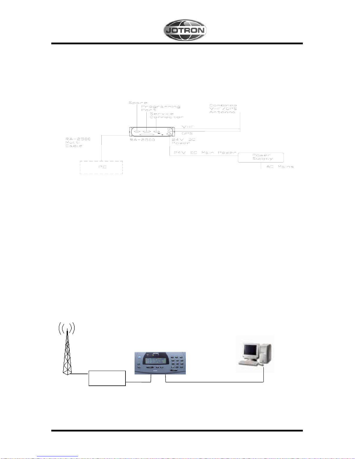
3 RA-2500 CONFIGURATION
Figure 3.0, Complete Tron RA-2500 system.
(Dotted lines in the figure above, means options)
3.1 Using serial interface (through “External display” port)
When using this port, the RA-2500 needs a PC to connect and control the data flow.
For connection details, see chapter-------
PC with compatible
charting software
Figure
3.1, Communication between the RA-2500 and the PC is through the RS232 interface
communicating on 38400 bits/second (baud).
RA-2500
VHF & GPS Antenna
Protection
and filters
Serial interface cable
Page 17

82694_Op&Ins MAN_RA2500_D 3-2
3.2 Using Ethernet interface
Using this port, the RA-2500 is connected to the Ethernet port on a PC or a network node.
See chapter 7.3 for description of LAN connector.
3.3 Not all ships carry AIS
It is important to remember that not all ships carry AIS, in particular leisure crafts, fishing boats,
warships and some costal shore stations including Vessel Traffic Service Centers.
3.4 Use of AIS in collision avoidance
As an anti-collision aid the AIS has some advantages over radar:
- Information provided in near real-time.
- Capable of instant presentation of target course alternations.
- Not subject to target swap.
- Not subject to target loss in clutter.
- Not subject to target loss due to fast maneuvers.
- Able to detect ships within VHF/FM coverage.
-
IMPORTANT
When using the AIS for anti-collision purposes it is important to remember that the AIS is an
additional source of navigation information. It does not replace other navigational systems. The AIS
may not separately always give the right picture of the traffic in your area.
3.5 Erroneous information
Erroneous information implies a risk to other ships as well as your own. Poorly configured or
calibrated sensors might lead to transmission of incorrect information. It is the users responsibility
to ensure that all information entered into the system is correct and up to date.
Page 18
82694_Op&Ins MAN_RA2500_D 3-3
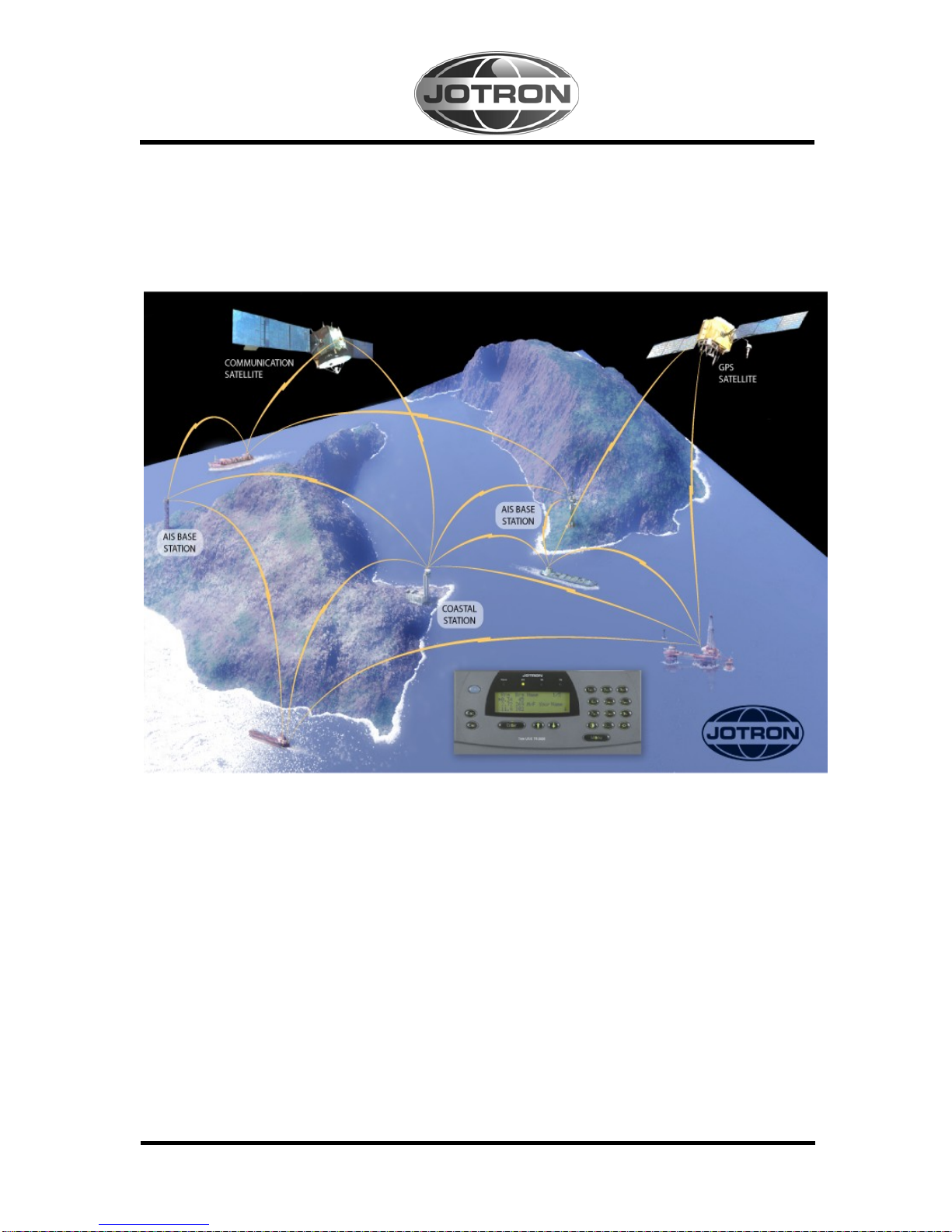
3.6 AIS in an Operational Environment
This illustration shows a typical AIS system where equipped ships, vessels and shore-based
systems are automatically communicating with each other.
Figure
3.6, The total UAIS system.
Page 19

82693_Op&Ins MAN_TR2500_D 4-1
4 INSTALLATION
Important notice
In a radio environment, depending of frequency and antenna separation, it may be necessary
to use cavity filters to avoid transmitter noise and receiver blocking problems.
4.1 Antennas
4.1.1 GPS antenna location
Install the GPS antenna unit referring to figure 4.1.3. When selecting a mounting location for the
antenna, keep in mind the following points.
1. Select a location out of the radar beam. The radar beam will obstruct or prevent reception
of the GPS satellite signal.
2. There should be no interfering object within the line-of-sight to the satellites. Objects
within line-of-sight to a satellite, for example a mast, may block reception or prolong
acquisition time.
3. Mount the antenna unit as high as possible to keep it free of interfering objects and water
spray, which can interrupt reception of GPS satellite signal it the water freezes.
4.1.2 VHF antenna location
Location of the mandatory AIS VHF-antenna should be carefully considered. Digital
communication is more sensitive than analogue/voice communication to interference created by
reflections in obstructions like masts and booms. It may be necessary to relocate the VHF
radiotelephone antenna to minimize interference effects.
Install the VHF whip antenna referring to figure 4.1.3. Separate this antenna from other VHF
radiotelephone antennas to prevent interference to the RA-2500.
To minimise interference effects, the following guidelines apply:
1. The AIS VHF antenna should be placed in an elevated position that is as free as possible
with a minimum of 0.5 meters in the horizontal direction from constructions made of
conductive materials. The antenna should not be installed close to any large vertical
obstruction. The objective for the AIS VHF antenna is to see the horizon freely through
360 degrees.
2. The AIS VHF antenna should be installed safely away from interfering high-power
energy sources like radar and other transmitting radio antennas, preferably at least 3
meters away from and out of the transmitting beam.
Page 20

82694_Op&Ins MAN_RA2500_D 4-2
3. There should not be more than one antenna on the same plane. The AIS VHF antenna
should be mounted directly above or below the ship's primary VHF radiotelephone
antenna, with no horizontal separation and with a minimum of 2.8 meters vertical
separation. If it is located on the same plane as other antennas, the distance apart should
be at least 10 meters.
4.1.3 GPS/VHF combined antenna
See figure 4.1.3. Select a location out of the radar beam. The radar beam will obstruct or prevent
reception of the GPS satellite signal.
There should be no interfering object within the line-of-sight to the satellites. Objects within lineof-sight to a satellite, for example, a mast, may block reception or prolong acquisition time.
Mount the antenna unit as high as possible. Mounting it this way keeps it free of interfering objects
and water spray, which can interrupt reception of GPS satellite signal if the water freezes.
Horizontal separation distance:
>aa meters
VHF antenna for AIS:
Other VHF antenna
or GPS antenna
Figure
4.1.3a, Example of horizontal distance between antennas
Page 21

82694_Op&Ins MAN_RA2500_D 4-3
Vertical separation distance and distance from mast or other object of metal:
Vertical separation distance: Vertical separation distance:
VHF antenna for AIS:
More than bb
Other VHF
>0,5 meter
More than bb
GPS
antenna
>0,5 meter
VHF antenna for AIS:
Figure 4.1.3b, Examples of vertical distance between antennas
4.2 Cabling
The cable should be kept as short as possible to minimize signal attenuation.
The table below gives recommendations on cables that can be used for the GPS antenna
connections:
Type Attenuation
@1.5 GHz
(dB/100m)
Remark
RG58 90 Default for use if length< 20 m and antenna = Procom
GPS4
RG214 35 If combined GPS/VHF antenna from either Procom or
Comrod is used, this or better can be used
RG225 30 Cable with lower loss
Page 22

82694_Op&Ins MAN_RA2500_D 4-4
For optimum performance of the transponder approximately +10dB gain should be available
when the cable attenuation has been subtracted from the GPS antenna preamplifier gain. Note
that Procom AIS2/GPS and Comrod AC17-AIS are combined VHF/GPS antennas and additional
attenuation from connectors/ diplexer must be taken in consideration. Some examples below:
Cable Type Antenna Preamplifier Gain
(dB/100m)
Recommended cable
length (m)
RG58 Procom GPS4 30 <20 meter
Procom AIS2/GPS 28 10-30 meter RG214
Comrod AC17-AIS 20 10-20 meter
Procom AIS2/GPS 28 10-40 meter RG225
Comrod AC17-AIS 20 10-30 meter
The table below is gives you the attenuation on the VHF frequencies with different cable types:
Cable Type Attenuation
@150 MHz
(dB/100m)
Diameter (mm) Weight (kg/100m)
RG214 7 10,8 18,5
RG225 8 10,9 23,3
Example : A RG 214 cable with length of 40 meters will have an attenuation of 2,8 dB.
Please keep the cables as short as possible, and be aware that 3 dB loss means only half the output
power. If you have a transmitter delivering 12,5 W, and you have 3 dB loss in the cable, only 6,25
Watts will be at the antenna.
4.2.1 Cable installation
All outdoor installed connectors on coaxial cables should be fitted with preventive isolation such as
vulcanizing tape to protect against water penetration into the antenna cable.
Coaxial cables should be installed in separate signal cable channels/tubes and at least 10 cm away
from power supply cables. Crossing of cables should be done at right angles (90°). The minimum
bend radius of the coaxial cable should be 5 times the cable's outer diameter.
Page 23

82694_Op&Ins MAN_RA2500_D 4-5
4.3 Receiver unit
When selecting a mounting location for the receiver the following guidelines apply:
1. Keep the receiver out of direct sunlight.
2. The temperature and humidity should be moderate and stable.
3. The mounting location should be well ventilated.
4. Mount the unit where shock and vibration are minimal.
5. Keep the unit away from electromagnetic field generating equipment such as motor and
generator.
6. Leave sufficient space at the sides and rear of the unit for maintenance and repair. Do also
leave slack in cables for same reason.
4.3.1 Desktop Mounting
Use the standard Mounting Kit. For mounting hole measurements see Figure 4.3.3.
Figure 4.3.1, Desktop Mounting
Page 24

82694_Op&Ins MAN_RA2500_D 4-6
4.3.2 Roof Mounting
Use the standard Mounting Kit for desktop mounting.
The bracket plates 1 and 2 must be switched over to opposite side and the bracket is turned 180
degrees in order to get the bracket in place for roof mounting.
For mounting hole measurements see Figure 4.3.3.
Figure 4.3.2a, Roof Mounting
1
2
2
Figure 4.3.2b, Roof Mounting
Page 25

82694_Op&Ins MAN_RA2500_D 4-7
4.3.3 Bracket mounting hole measurements
Figure 4.3.3, Bracket mounting hole measurements
4.3.4 Flush Mounting
Use the Flush Mounting Kit 80586. For mounting hole measurements see Figure 4.3.4b.
Figure 4.3.4a, Flush Mounting
Figure 4.3.4b Flush Mounting Panel cutout
Page 26

82694_Op&Ins MAN_RA2500_D 4-8
4.3.5 19``Rack Tray Mounting
Use the 19`` Rack Tray Mounting Kit 80587. For mounting see Figure 4.3.5b
Figure 4.3.5a, Rack Tray Mounting
Figure 4.3.5b, Rack Tray Mounting
Page 27

82693_Op&Ins MAN_TR2500_D 5-1
5 OPERATION
Figure 5.0, Front view RA-2500
5.1 Description of keys
:
Shortcut to insert navigational data
Menu
:
Show main menu
Enter
:
Accept current setting.
Takes you one menu level forward.
Enter sub-menu
Esc
:
Escape from current menu without saving.
Takes you one menu level back.
Del
:
Delete character at cursor
↑ ↓
:
Scrolling menus
☼
:
Adjust light intensity in display and keyboard buttons.
:
Adjust contrast in display.
0-9
:
Digits 0-9.
Press keys with a short time interval to convert it to
alphabetical character.
Nav
Page 28

82694_Op&Ins MAN_RA2500_D 5-2
5.2 Menus
5.2.1 Menu Flowchart
Main Menu 1/4
1 Current Sensors
2 Internal GPS
3 Diagnostic
4 Config
Esc
Enter
Menu
Rng Brg Name: 1/6
1384 124 NIKITA
1754 124 COLOR FESTIV
99.1 098 PETER VESSEL
NIKITA 1/14
MMSI: 444
Call:
ETA: ----:0000
Dest: VIKSFJORD
Type:0
Lat: N58d52.58
Lon: E010d45.51
SOG: 10.0 KT
COG: 3.2
Head: 45
Length: -- Beam:-- Draught:
Nav.Stat
Menu: Current Senso 1/5
LAT: N 5903.21
LON: E 01007.44
Pos Accur.: Low
Pos Source: Internal
HH:MM:SS DD/MM/YYYY
Menu: Internal GPS 1/4
LAT: ---
LON:-- Status: NoFix
DD.MM.YY HH:MM:SS
Menu: Diagnostic 1/6
1 BIIT
2 Alarm
3 System Indicators
4 History
5 SW Versions
6 Service
Esc
Enter key 1 to 4
Esc
Esc
Esc
Esc
How to navigate in the
menus/submenus
If there is a number in front of the
menu/submenu, you can select it
directly by pressing the numeric key
with the corresponding number.
When no number is present in front
of a submenu, use the arrow
up/down keys ↓ to choose and
press [Enter] key to select.
The [Esc] key takes you one step
back.
Enter
Menu: Config 1/4
1 Recv. Channels
2 Position Source
3 I/O Ports
4 Buzzer
Page 29

82694_Op&Ins MAN_RA2500_D 5-3
5.3 Connecting power
After connecting the antennas and Inputs/Outputs, the DC power can be connected to the RA-2500.
The input voltage must be within 24VDC +30% / -10%. The power consumption is 17W. At start,
the RA-2500 will look for connected sensors and equipment for 20 –30 seconds. The display will
show:
Loading …
Please wait
After a while the alarm status will be indicated. Press [Del] key to reset the alarm settings.
If the RA-2500 has been previous configured, and the configuration is OK, there is no need to go
further in this chapter. Otherwise continue with chapter 9.2.1.
5.3.1 LAN configuration
Press [Menu] key to enter “Main menu”.
Showing the number of
sub-menus available
below the selected menu
Main Menu 1/4
1 Current Sensors
2 Internal GPS
3 Diagnostic
4 Config
Select “Config” by [arrow down] key.
Press [Enter] key.
Page 30

82694_Op&Ins MAN_RA2500_D 5-4
Menu: Config 1/4
1 Recv. Channels
2 Position Source
3 I/O Ports
4 Buzzer
Select ‘ I/O Ports” followed by [Enter] key
5.3.1.1 Set Own IP address
Select “Own IP address” then [Enter] key
Now the IP address of the RA-2500 can be entered.
Menu: I/O Ports 2/3
1 Speed .
X 2 Own IP Address W
3 VTS IP Address
Menu: Own IP Addr 1/2
X 1 IP = 0.0.0.0 W
2 Port = 5000
Enter an unique IP address on the network you are connected. See chapter 5.3.1.2.
The Port number is default to “5000”, but can be altered. This must of course be the same on the
RA-2500 and the computer connected.
Press [Enter] when done. When you have saved the settings, you will press [ESC] to return to
previous menu levels.
Page 31

82694_Op&Ins MAN_RA2500_D 5-5
5.3.1.2 Selection of IP address
Be shure that Own IP and VTS IP is within the same subnet.
The configuration of Unicast, Multicast or Broadcast is dependent of the map system and the date
network available. See this table for address limitations within the different groups and classes.
Class Own IP
address
VTS IP Unicast VTS IP Multicast
address
VTS IP
Broadcast
5.4 Normal use
5.4.1 Display received vessels
Normal use operational display
Select the name of the ship by pressing [arrow down] key and [Enter] key.
Rng Brg Name: 1/3
1384 124 NIKITA
1754 124 COLOR FESTIV
99.1 098 PETER VESSEL
Range to ship in
nautical miles
Bearing of the
received ship..
Name of the
received ship.
address
address
Min Max Min Max Min Max Fixed
A
10.0.0.0 10.255.255.254 10.0.0.0 10.255.255.254 224.0.0.0 239.255.255.255 10.255.255.255
B
172.16.0.0 172.31.255.254 172.16.0.0 172.31.255.254 172.16.0.0 172.31.255.254 172.31.255.255
C
192.168.0.0 192.168.0.254 192.168.0.0 192.168.0.254 192.168.0.0 192.168.0.254 192.168.0.255
Page 32

82694_Op&Ins MAN_RA2500_D 5-6
NIKITA 3/14
MMSI: 444
Call:
ETA: ----:0000
Dest: VIKSFJORD
Type:0
Lat: N58d52.58
Lon: E010d45.51
SOG: 10.0 KT
COG: 3.2
Head: 45
Length: -- Beam:-- Draught:
Nav.Stat
Select specific information by pressing [arrow down] key and [Enter] key.
ETA:
30 /09 23:59
DD/MM HH:MM
< >
Press [Esc] key twice to go to “Main Menu”.
5.4.2 Current Sensors / Dynamic Data menu
Main Menu 1/4
1 Current Sensors
2 Internal GPS
3 Diagnostic
4 Config
Select “Current Sensor” with numeric key [1] or [arrow down] key and [Enter] key.
Page 33

82694_Op&Ins MAN_RA2500_D 5-7
Menu: Current Senso 1/5
LAT: ---
LON:-- Pos. Accur.: Low
Pos. Source: Internal
HH:MM:SS DD/MM/YYYY
This menu shows the data from the selected sensors onboard that
the RA-2500 is receiving.
Press [Esc] key twice to return to “Main Menu”.
5.4.3 Internal GPS Menu
From the “Main Menu” select “Internal GPS” by pressing numeric key [4]
or [arrow down] key and [Enter] key.
Menu: Internal GPS 1/4
LAT: ---
LON:
Status: SPS 3D
DD.MM.YY HH:MM:SS
This menu shows the data from the internal GPS module.
Press [Esc] key twice to return to “Main Menu”.
5.4.4 Diagnostic Menu
From the “Main Menu” select “Diagnostic” by pressing numeric key [3]
or [arrow down] key and [Enter] key.
Menu: Diagnostic 1/6
1 BIIT
2 Alarm
3 System Indicators
4 History
5 SW Versions
6 Service
Page 34

82694_Op&Ins MAN_RA2500_D 5-8
This menu gives access to different submenus for readout of parameters.
The only submenu who can give access to changes is the “Service” menu which
is password protected.
Select “BITE” menu by pressing [Enter] key or numeric key [1].
Menu: BIIT 1/3
Temperature:
Rssi AIS0….:
Rssi AIS1.…:
This menu gives BIIT readout values from the receiver.
Press [Esc] key to go one step back. Select “Alarm Status”
menu by pressing numeric key [2] or [arrow down] key and press [Enter ] key.
This menu shows the log over momentarily status alarms that have been visualized
in the AIS display and signed for by pressing [Del] key, but are still valid.
Press [Esc] key to go one step back. Select “System Indicators” menu
by pressing numeric key [3] or [arrow down] key and press [Enter] key.
This menu shows the momentarily status if sensor is connected.
Press [Esc] key to go one step back. Select “History” menu
by pressing numeric key [4] or [arrow down] key and press [Enter ] key.
Menu: Alarm Status 1/1
EPFS
Menu: Indicators 1/2
UTC clock OK
Int. GNSS
Menu: History 1/14
Off 19 Feb 2038 03:14
Off 20 Feb 1030 02:07
Off 26 Feb 2029 23:44
This menu shows the log over when the receiver have been
turned off for more than 15 min. Press [Esc] key to go one step back.
Page 35

82694_Op&Ins MAN_RA2500_D 5-9
Select “SW Version” menu by pressing numeric key [5] or [arrow down] key and press [Enter ]
key.
This menu shows the different software versions installed in the receiver.
To get the Compilation date for each software version, select the software by
[arrow up/down] keys and press [Enter] key.
This shows the Compilation date and time for this specific software.
Press [Esc] key to go one step back. Repeat the procedure for the other
software versions. Press [Esc] key twice to go back to “Main” menu.
5.4.5 Config Menu
From “Main” menu select “Config” menu by pressing numeric key [4] or [arrow down] key and
press [Enter] key.
Menu: SW-Version 1/6
RA 00.00.06
ECRA 01.00.03
MMI RA_01.00.00
LINK : 02.00.09
RF: 02.00.08
HW: BD
Compilation date 1/2
ECRA 01.00.03
Feb 21 2005 09:29:57
Menu: Config 1/4
1 Recv. Channels
2 Position Source
3 I/O Ports
4 Buzzer
Page 36

82694_Op&Ins MAN_RA2500_D 5-10
5.4.5.1 Receiver channels
Select “Recv. Channels.” menu by pressing numeric key [1] or [arrow up/down] keys and press
[Enter ] key.
Menu: Recv. Channel 1/2
1 Ch.A: 2087
Ch.B 2088
From this menu it is possible to set the frequencies of the two receiving channels.
Set value for selected channel. Repeat for Ch. B.
5.4.5.2 Positioning Source
From “Config” menu select “Positioning Source” menu by pressing numeric key [2] or [arrow
up/down] keys and press [Enter ] key.
Select between Internal, External or Surveyed source.
Ch. A:
2087
Range: 0 to 2287
Save Changes?
No
↑=No ↓=Yes
Menu: Pos source 1/1
Source: Internal
Source:
Internal
↑=Surv ↓=Exte
Select by using the arrow keys.
Page 37

82694_Op&Ins MAN_RA2500_D 5-11
Source:
Surveyed
↑=Inte
The Surveyed source is a static precise position to be entered manually for a RA-2500.
Menu: Pos. Source
Source: Surveyed
Lat: 9100.000
Dir.: South
Lon.: 18100.0000
Dir.: West
Pos.Acc: Low
Press [Esc] key to go back to “Config” menu.
5.4.5.3 I/O Ports
From “Config” menu select “I/O Ports” menu by pressing numeric key [3] or [arrow up/down] keys
and press [Enter ] key.
Menu: I/O Ports - Sp 1/3
1. Speed
2. Own IP Address
3. VTS IP Address
Press [Enter] key or numeric key [1] to select data speed .
Menu: I/O Ports - Sp 1/6
P1 (Sensor1) 4800
P2 (Sensor2) 4800
P3 (Sensor3) 4800
P4 (Ext. disp.) 38400
P5 (Pilot) 38400
P6 (Spare) 38400
This menu allows the setting of data speed at port1 to port 6 of 4800 b/s or 38400 b/s.
Press [Enter] key to select “P1”.
Page 38

82694_Op&Ins MAN_RA2500_D 5-12
P1 (Sensor1)
4800
↑=4800 ↓=3840
Select speed using [arrow up/down] keys and press [ Enter] key
Repeat the prosedure for all ports.
Press [Esc] key to return
Save Changes ?
No
↑= No ↓= Yes
Confirm changes by [arrow up/down] keys and press [ Enter] key
5.4.5.4 Buzzer
From “Config” menu select “Buzzer” menu by pressing numeric key [5] or [arrow down] key and
[Enter] key.
Menu: Buzzer 1/3
1 Keyboard LOW
2 Info Beep On
3 Messages Off
Select “Keyboard” menu by pressing numeric key [1] or [Enter] key.
Keyboard:
LOW
↑= Off ↓= On
Select keyboard status with [arrow up/down] keys and [Enter] key.
Repeat procedure for “Info Beep” and “Messages”.
Press [Esc] key twice to return to “Config” menu.
Page 39

82694_Op&Ins MAN_RA2500_D 5-13
5.5 Description of sentence format
The following provides a summary explanation of the approved sentence structure:
$aaccc, c---c*hh<CR><LF>
ASCII HEX Description
"$" 24 Start of sentence: starting delimiter
aaccc Address field: alphanumeric characters identifying type of talker,
and sentence formatter. The first two characters identify the
talker. The last three are the sentence formatter mnemonic code
identifying the data type and the string format of the successive
fields. Mnemonics will be used as far as possible to facilitate
read-outs by users.
"," 2C Field delimiter: starts each field except address and checksum
fields. If it is followed by a null field, it is all that remains to
indicate no data in a field.
c---c Data sentence block: follows address field and is a series of data
fields containing all of the data to be transmitted. Data field
sequence is fixed and identified by the third and subsequent
characters of the address field (the sentence formatter). Data
fields may be of variable length and are preceded by delimiters ",".
"*" 2A checksum delimiter: follows last data field of the sentence. It
indicates that the following two alpha-numeric characters show
the HEX value of the checksum.
hh Checksum field: the absolute value calculated by exclusive-
OR'ing the eight data bits (no start bits or stop bits) of each
character in the sentence between, but excluding, "$" and "*".
The hexadecimal value of the most significant and least
significant four bits of the result are converted to two ASCII
characters (0-9, A-F) for transmission. The most significant
character is transmitted first. The checksum field is required in all
cases.
<CR><LF> 0D 0A End of sentence: sentence terminating delimiter.
Page 40

82694_Op&Ins MAN_RA2500_D 5-14
5.6 Input
5.6.1 Definitions
1. BCFQ = Query BCF message from RA-2500
When the RA-2500 receives a Query, it responds with a BCF message.
2. BCF = Configure Rx channels, Position source and Talker ID at RA-2500
5.6.2 Receiving actions
VDL Input Resulting PI Output Resulting VDL Output
Message 1 VDM Nil
Message 2 VDM Nil
Message 3 VDM Nil
Message 4 VDM Nil
Message 5 VDM Nil
Message 8 VDM Nil
Message 9 VDM Nil
Message 11 VDM Nil
Message 12 VDM Nil
Message 14 VDM Nil
Message 16
VDM Nil
Message 17 VDM
Nil
Message 18 VDM Nil
Message 19 VDM Nil
Message 20 VDM Nil
Message 21 VDM Nil
Message 22 VDM Nil
Page 41

82694_Op&Ins MAN_RA2500_D 5-15
5.6.3 Format BCF:
Configure RA-2500 parameters. See paragraph 10.2.1 section 2.
$--BCF, xxxxxxxxx,x, llll.ll, a, yyyyy.yy, a, x, xxxx, xxxx, xxxx,xxxx,x,x,x,x,cc*hh<CR><LF>
receiver Talker ID
N/A
N/A
N/A
N/A
N/A
N/A
Rx channel B
4
Rx channel A
4
Position accuracy
3
Longitude E/W
2
Latitude N/S
2
Position source
1
N/A
Notes:
1. Identifies the source of the position.
Value 0 = surveyed position
Value 1 = internal source
Value 2 = external source
2. Surveyed position of the base station. The position is only applicable to fixed base stations.
Within the base station, the "electronic position fixing device" parameter is set to a value of
7 indicating a surveyed position. Mobile or non-fixed base stations receive their position
information by another means.
3. 0 = low > 10m.
1 = high < 10m ; differential mode of DGNSS.
4. VHF channel number, see paragraph
9
Page 42

82694_Op&Ins MAN_RA2500_D 5-16
5.7 Output
All sentences starts with a delimiter that can be “$” or “!” followed by the talker identifier indicated
by “- -“. The talker identifier is AI for AIS.
5.7.1 Definitions
1. VDM = All received VDL messages (except addressed Binary and Safety messages) are
forwarded in a VDM message to the Management System.
2. BCF = Configure Rx channels, Position source and Talker ID at RA-2500.
3. GGA = Forward internal GPS data if position source internal.
4. VTG = Forward internal GPS data if position source internal.
5. GLL = Forward internal GPS data if position source internal.
6. ALR = Position alarm.
7. TXT = UTC status, Position source status.
5.7.2 VDM VHF Data-link Message
This sentence is used to transfer the entire contents of a received AIS message packet, as
defined in ITU-R M.1371 and as received on the VHF Data Link (VDL), using the "6-bit" field
type.
!--VDM,x,x,x,a,s--s,x*hh<CR><LF>
Number of fill-bits, 0 to 5
Encapsulated ITU-R M.1371 radio message
AIS Channel, "A" or "B"
Sequential message identifier, 0 to 9
Sentence number, 1 to 9
Total number of sentences needed to transfer the message, 1 to 9
Page 43

82694_Op&Ins MAN_RA2500_D 5-17
5.7.3 ALR - Set alarm state.
Local alarm condition and status. This sentence is used to report an alarm condition on a
device and its current state of acknowledgement.
$--ALR,hhmmss.ss,xxx,A, A,c--c*hh<CR><LF>
Alarm's description text
Alarm's acknowledge state, A = acknowledged
V = unacknowledged
Alarm condition (A = threshold exceeded, V = not exceeded)
Local alarm number (identifier)
Time of alarm condition change, UTC
alarms description text
Alarm condition
threshold exceeded
Alarm condition not
exceeded
alarm ID or text identifier
reaction of the system to the alarm
condition threshold exceeded
AIS: Rx channel 1 malfunction A V 003
AIS: Rx channel 2 malfunction A V 004
AIS: general failure A V 006
AIS: No sensor position in use A V 026 Continue operation
5.7.4 TXT Text transmission
For the transmission of short text messages. Longer text messages may be transmitted by
using multiple sentences.
$--TXT,xx,xx,xx,c--c*hh<CR><LF>
Text message, ASCII, up to 61 characters
Text identifier, 01-99
Message number, 01 to 99
Total number of messages, 01 to 99
Page 44

82694_Op&Ins MAN_RA2500_D 5-18
Text message
Text identifier
reaction of the system
AIS: UTC clock lost 007 Continue operation using indirect or semaphore
synchronisation
AIS: external DGNSS in use 021 Continue operation
AIS: external GNSS in use 022 Continue operation
AIS: internal DGNSS in use (beacon) 023 Continue operation
AIS: internal DGNSS in use (msg 17) 024 Continue operation
AIS: internal GNSS in use 025 Continue operation
AIS: surveyed position in use 041 Continue operation
AIS: UTC clock OK 042 Continue operation
AIS: System Started 051 Continue operation
5.7.5 GLL Geographic position latitude/longitude
Latitude and longitude of vessel position, time of position fix and status.
$--GLL, llll.ll, a, yyyyy.yy, a, hhmmss.ss, A, a *hh<CR><LF>
Mode indicator
Status: A = data valid V = data invalid
Time of position (UTC)
Longitude , E/W
Latitude, N/S
NOTE: Positioning system Mode indicator:
A = Autonomous
D = Differential
E = Estimated (dead reckoning)
M = Manual input
S = Simulator
N = Data not valid
Page 45

82694_Op&Ins MAN_RA2500_D 5-19
5.7.6 GGA Global positioning system (GPS) fix data
Time, position and fix-related data for a GPS receiver.
$--GGA, hhmmss.ss, llll.ll, a, yyyyy.yy, a, x, xx, x.x, x.x, M, x.x, M, x.x, xxxx*hh<CR><LF>
Differential reference station ID
0000-1023 (Not used)
Age of diff. GPS data (Not used)
Units of geoidal separation,m (Not
used)
Geoidal separation (Not used)
Units of antenna altitude, m (Not
used)
Antenna altitude above/below
mean sea level (geoid) (Not used)
Horizontal dilution of precision (Not
used)
No. of satellites in use, 00-12 (Not
used)
GPS quality indicator
Longitude E/W
Latitude N/S
UTC time of position
Page 46

82693_Op&Ins MAN_TR2500_D 6-1
6 EQUIPMENT LIST
6.1 Standard supply 80500
No. Name Type Stock No. Qty.
1
Receiver unit RA-2500
80500
1
2
Operators & Installation Manual
81984
1
3
Standard Bracket Kit For Desktop or Roof
mounting of RA-2500
81540 1
4
AC/DC External power supply 230VAC to 24VDC 81830 1
5
Power connector For 24CDC to RA-2500 81509 1
6
Combined GPS and VHF antenna 81903 1
7
RS232 Cable 37pin to 9pin 2.5m
82092
1
8
AIS Graphical Viewer v.1.2.2.or
higher w/manual
CD-R
81650
1
6.2 Optional supply
Name Type Stock No.
RS422 to RS232
converter
Allows 30m connection cable 81905
LAN cable 5m 9pin D-sub to RJ45
82159
GPS antenna
with mounting bracket
Transvoice type 202-968
with 200-456/200-233 bracket
80618
Plug Kit for 80618 81534
GPS/VHF combined
antenna
Comrod AC17-AIS 80747
Plug Kit for 80747 81536
Signal splitter 80747 81768
VHF antenna
w/mounting bracket
Transvoice 80617
Plug Kit 80617 80597
Flush Mounting Kit 80586
19`` Rack Tray
Mounting Kit
80587
Page 47

82693_Op&Ins MAN_TR2500_D 7-1
7 WIRING AND CONNECTIONS
7.1 RA-2500 Rear Connections
1
2
3
8
6
7
4
5
1. VHF Antenna Connector
This is a BNC type antenna connector to be connected directly to an external VHF antenna
or antenna splitter to receive and transmit VHF frequencies.
For further information see chapter 8.9.
2. GPS Antenna Connector
This is a TNC type antenna connector to be connected directly to an external GPS antenna or
antenna splitter to receive GPS information.
For further information see chapter 8.10.
3. 24VDC Connector
This is a connector to connect 24VDV power to the receiver.
For further information see chapter 6.7 and 8.13.
4. Ground Tag (GND)
This Ground Tag is to be connected directly to the ships metal.
5. LAN Connector
See chapter 7.4
Page 48

82694_Op&Ins MAN_RA2500_D 7-2
6. Junction Box Connector
See chapter 7.2
7. Programming Connector
This 15 pin D-sub connector is for programming of the Receiver by Program Engineers
only.
8. Extra I/O Connector
This 9 pin D-sub connector is not described. Factory use only.
7.2 Description of Junction Box Connector
37 Pin D-sub
RA-2500
Functions Input / Output
13 AIS TD4-B (External
Display)
Out
14 AIS TD4-A (External
Display)
Out
Isolated GND
15 AIS RD4-B In
16 AIS RD4-A In
Isolated GND
17 AIS TD5-B
18 AIS TD5-A
Isolated GND
19 AIS RD5-B
20 AIS RD5-A
Isolated GND
21 AIS TD6-B Out
22 AIS TD6-A Out
Isolated GND
23 AIS RD6-B In
24 AIS RD6-A In
Isolated GND
25 AIS TD7-B Reserved
26 AIS TD7-A Reserved
Isolated GND
27 AIS RD7-B
28 AIS RD7-A
Isolated GND
29 RS-232 TX Out
30 RS-232 RX In
31 Dry relay contact, Referred to
pin 48
Alarm Out
(NC)
32 Dry relay contact, Referred to
pin 48
Alarm Out
(NO)
33 Dry relay contact, Referred to
#46 & 47
Common
34 I/O Spare
35 Future warning for Backup
Power
36 GND
Page 49

82694_Op&Ins MAN_RA2500_D 7-3
7.3 Description of 24VDC connection to receiver
24VDC Connector for cable, front side
+ 24VDC
GND
0VDC
7.4 Description of LAN connector
Contains Ethernet 10Mbit Twisted pair interface and RS232 serial port with Tx and Rx.
Service connector, 9 pins Dsub:
Nr. Name Function In/Out
1 Ether_Tx+ Ethernet Transceive Data+ Out
2 Ether_Tx- Ethernet Transceive Data- Out
3 Ether_Rx+ Ethernet Receive Data+ In
4 Ether_Rx- Ethernet Receive Data- In
5 GND Ground 6
7
8 +14V +14 V, max 300mA. 9 NC Not Connected -
Page 50

82693_Op&Ins MAN_TR2500_D 8-1
8 ALARM MESSAGES
8.1 Receiver malfunction
If the error messages “Rx1”or “Rx2” appears on the LCD Display, this indicate that the test of the
TDMA receivers 1 or 2 has failed.
The alarm messages are as follows:
Alarm ID or text identifier Alarm description text
ID 003 AIS RX channel 1 malfunction
ID 004 AIS RX channel 2 malfunction
ID 006 AIS RX general failure
Page 51

82693_Op&Ins MAN_TR2500_D 9-1
9 LIST OF VHF CHANNELS
Channel
no. Frequency
Channel
no. Frequency
Channel
no. Frequency
Channel
no. Frequency
6 156.3000 1021 157.0500 1279 156.9775 2219 161.5625
8 156.4000 1022 157.1000 1280 157.0375 2220 161.6125
9 156.4500 1023 157.1500 1281 157.0875 2221 161.6625
10 156.5000 1024 157.2000 1282 157.1375 2222 161.7125
11 156.5500 1025 157.2500 1283 157.1875 2223 161.7625
12 156.6000 1026 157.3000 1284 157.2375 2224 161.8125
13 156.6500 1027 157.3500 1285 157.2875 2225 161.8625
14 156.7000 1028 157.4000 1286 157.3375 2226 161.9125
15 156.7500 1060 156.0250 1287 158.3875 2227 161.9625
16 156.8000 1061 156.0750 2001 160.6500 2228 162.0125
17 156.8500 1062 156.1250 2002 160.7000 2260 160.6375
67 156.3750 1063 156.1750 2003 160.7500 2261 160.6875
68 156.4250 1064 156.2250 2004 160.8000 2262 160.7375
69 156.4750 1065 156.2750 2005 160.8500 2263 160.7875
70 156.5250 1066 156.3250 2007 160.9500 2264 160.8375
71 156.5750 1078 156.9250 2018 161.5000 2265 160.8875
72 156.6250 1079 156.9750 2019 161.5500 2266 160.9375
73 156.6750 1080 157.0250 2020 161.6000 2278 161.5375
74 156.7250 1081 157.0750 2021 161.6500 2279 161.5775
75 156.7750 1082 157.1250 2022 161.7000 2280 161.6375
76 156.8250 1083 157.1750 2023 161.7500 2281 161.6875
77 156.8750 1084 157.2250 2024 161.8000 2282 161.7375
208 156.4125 1085 157.2750 2025 161.8500 2283 161.7875
209 156.4625 1086 157.3250 2026 161.9000 2284 161.8375
210 156.5125 1087 157.3750 2027 161.9500 2285 161.8875
211 156.5625 1088 157.4250 2028 162.0000 2286 161.9375
212 156.6125 1201 156.0625 2060 160.6250 2287 161.9875
213 156.6625 1202 156.1125 2061 160.6750
214 156.7125 1203 156.1625 2062 160.7250
215 156.7625 1204 156.2125 2063 160.7750
216 156.8125 1205 156.2625 2064 160.8250
217 156.8625 1206 156.3125 2065 160.8750
267 156.3875 1207 156.3625 2066 160.9250
268 156.4375 1218 156.9125 2078 161.5250
269 156.4875 1219 156.9625 2079 161.5750
270 156.5375 1220 157.0125 2080 161.6250
271 156.5875 1221 157.0625 2081 161.6750
272 156.6375 1222 157.1125 2082 161.7250
273 156.6875 1223 157.1625 2083 161.7750
274 156.7375 1224 157.2125 2084 161.8250
275 156.7875 1225 157.2625 2085 161.8750
276 156.8375 1226 157.3125 2086 161.9250
277 156.8875 1227 157.3625 2087 161.9750
1001 156.0500 1228 157.4125 2088 162.0250
1002 156.1000 1260 156.0375 2201 160.6625
1003 156.1500 1261 156.0875 2202 160.7125
1004 156.2000 1262 156.1375 2203 160.7625
1005 156.2500 1263 156.1875 2204 160.8125
1007 156.3500 1264 156.2375 2205 160.8625
1018 156.9000 1265 156.2875 2206 160.9125
1019 156.9500 1266 156.3375 2207 160.9625
1020 157.0000 1278 156.9375 2218 161.5125
Channel 2087 = Channel 87B Channel 2088 = Channel 88B
Page 52

82693_Op&Ins MAN_TR2500_D 10-1
10 OUTLINE DRAWINGS
10.1 TR-2500 AIS Transponder
Page 53

82694_Op&Ins MAN_RA2500_D 10-2
10.2 Procom CXL 2-1/l
Maritime VHF Antenna with FLG Bracket
Page 54

82694_Op&Ins MAN_RA2500_D 10-3
10.3 Procom GPS 4 Antenna
Page 55

82694_Op&Ins MAN_RA2500_D 10-4
10.4 BNC connector
95299, Suhner 24BNC-50-2-13/133NE
10.5 FME Connector Female
80588, Holund 40100
Page 56

82694_Op&Ins MAN_RA2500_D 10-5
10.6 BNC Connector Male
80577, Suhner 11BNC-50-2 / 133NE
10.7 TNC Connector Male
80578 Suhner 11TNC-3-6 / 133NE
Page 57

82694_Op&Ins MAN_RA2500_D 10-6
10.8 N Connector Male
80581, Suhner 11N-50-7-5 / 133NE
10.9 24VDC Power Connector
81509, AMP C091AT3261001
Page 58

82693_Op&Ins MAN_TR2500_D 11-1
11 REGISTRATION FORM
------------------------------------------------ Cut here and return this page to JOTRON ------------------------------------------------
RA-2500 Installation form
Data
Station name
Country
MMSI Number
Owner / Company
Office:
Contact
Name #1
Telephone Number(s)
GSM:
Office:
Contact
Name #2
Telephone Number(s)
GSM:
Comments:
RA-2500 AIS Receiver serial
number:
Installation completed and successfully commissioned by:
Technician, (type name)
Service provider / company
Place Date Signature
Please fill in with capital letters
This form must be returned to Jotron AS, Fax.: + 47 33 12 67 80
(attention service department) in order to have a valid 24 months product warranty.
Page 59

82694_Op&Ins MAN_RA2500_D 11-2
 Loading...