

Page 1

www.jotron.com
DOCUMENTATION HANDBOOK
BTS 4000
PHONTECH
BATTERYLESS TELEPHONE SYSTEM
Handbook page
1/52
Page 2

BTS 4000 Handbook contents:
Handbook page:
Batteryless Telephone System 4000
− System Description ……...…………………………………………… 08400-006-DE .………… 1
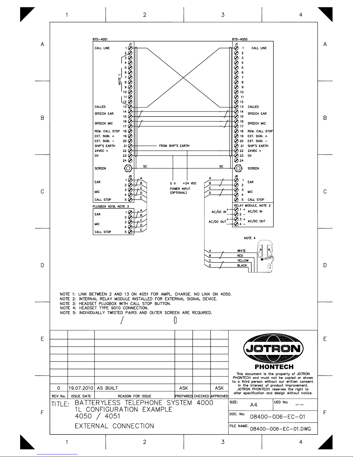
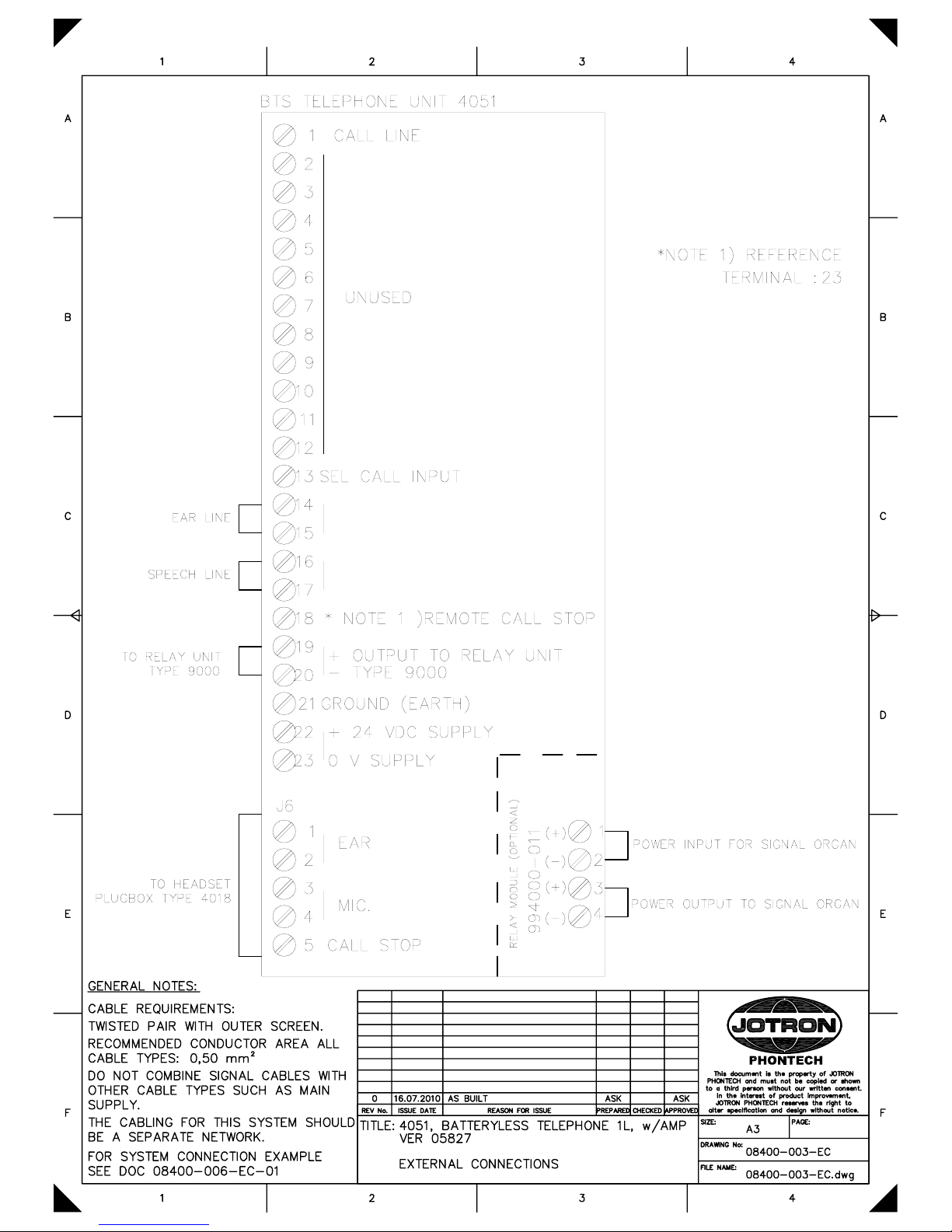
− External Connection , 1L. Configuration example, 4050/4051 …..… 08400-006-EC-01 ....…… 20
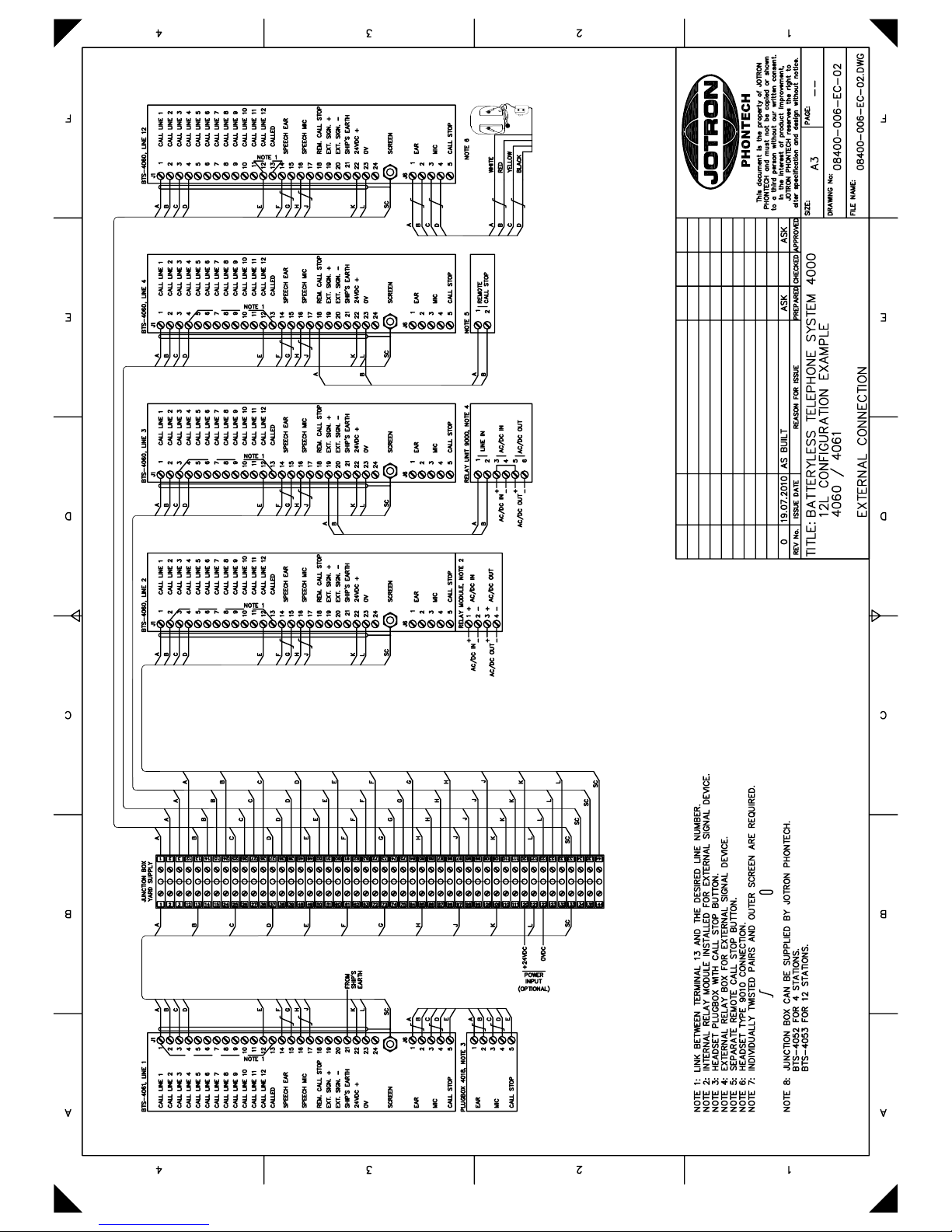
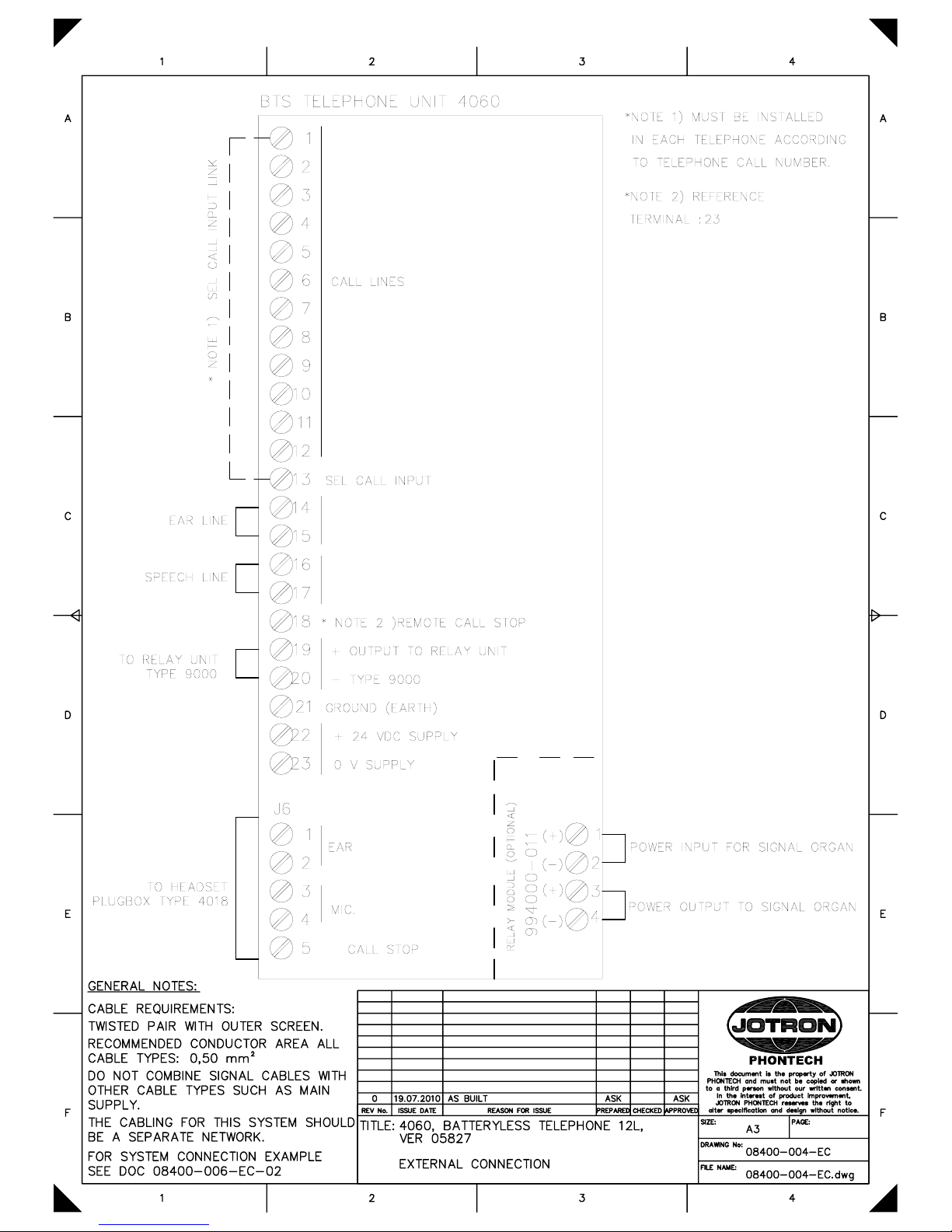
− External Connection , 12L. Configuration example, 4060/4061 …..... 08400-006-EC-02 ....…… 21
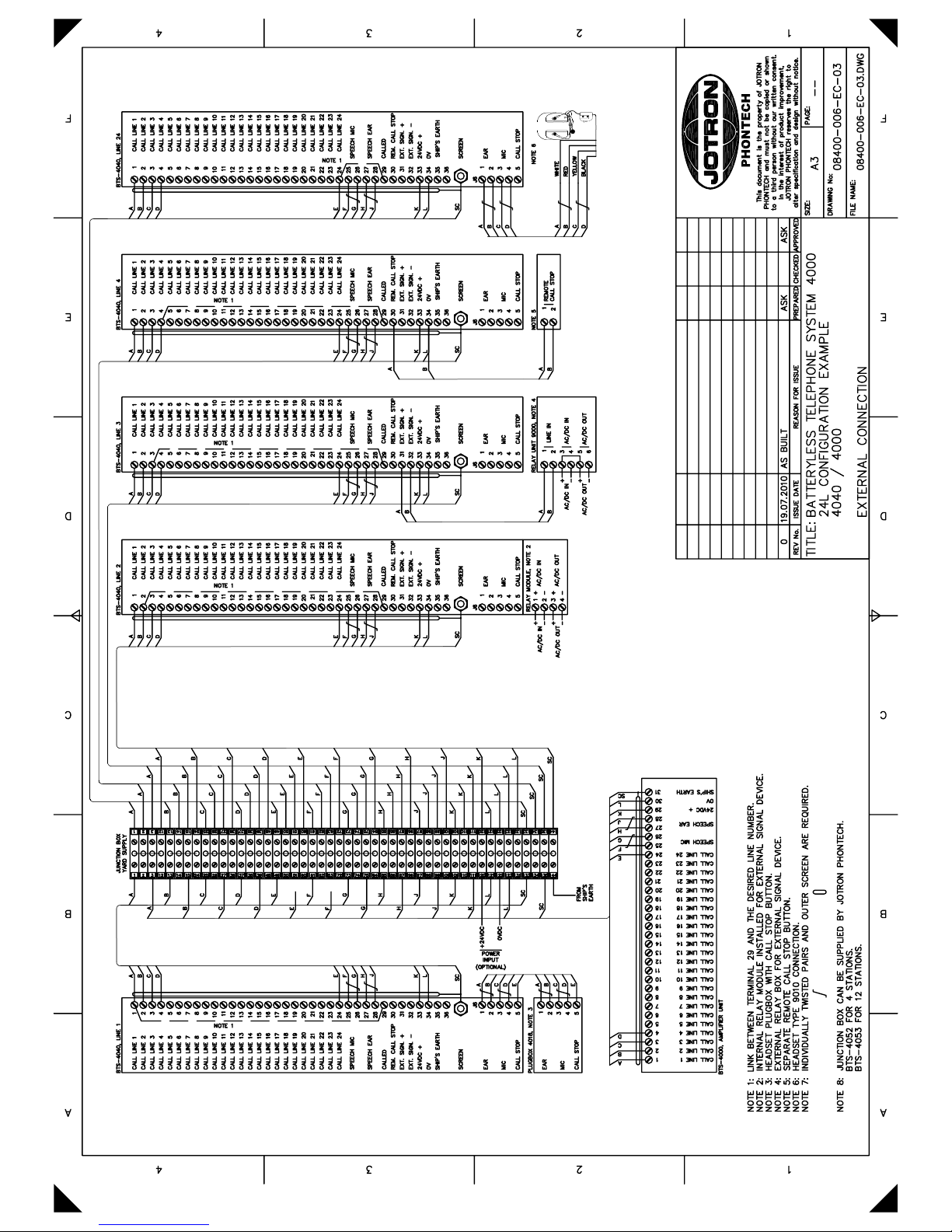
− External Connection , 24L. Configuration example, 4040/4000 …..… 08400-006-EC-03 ....…… 22
4040, Batteryless Telephone, 24L
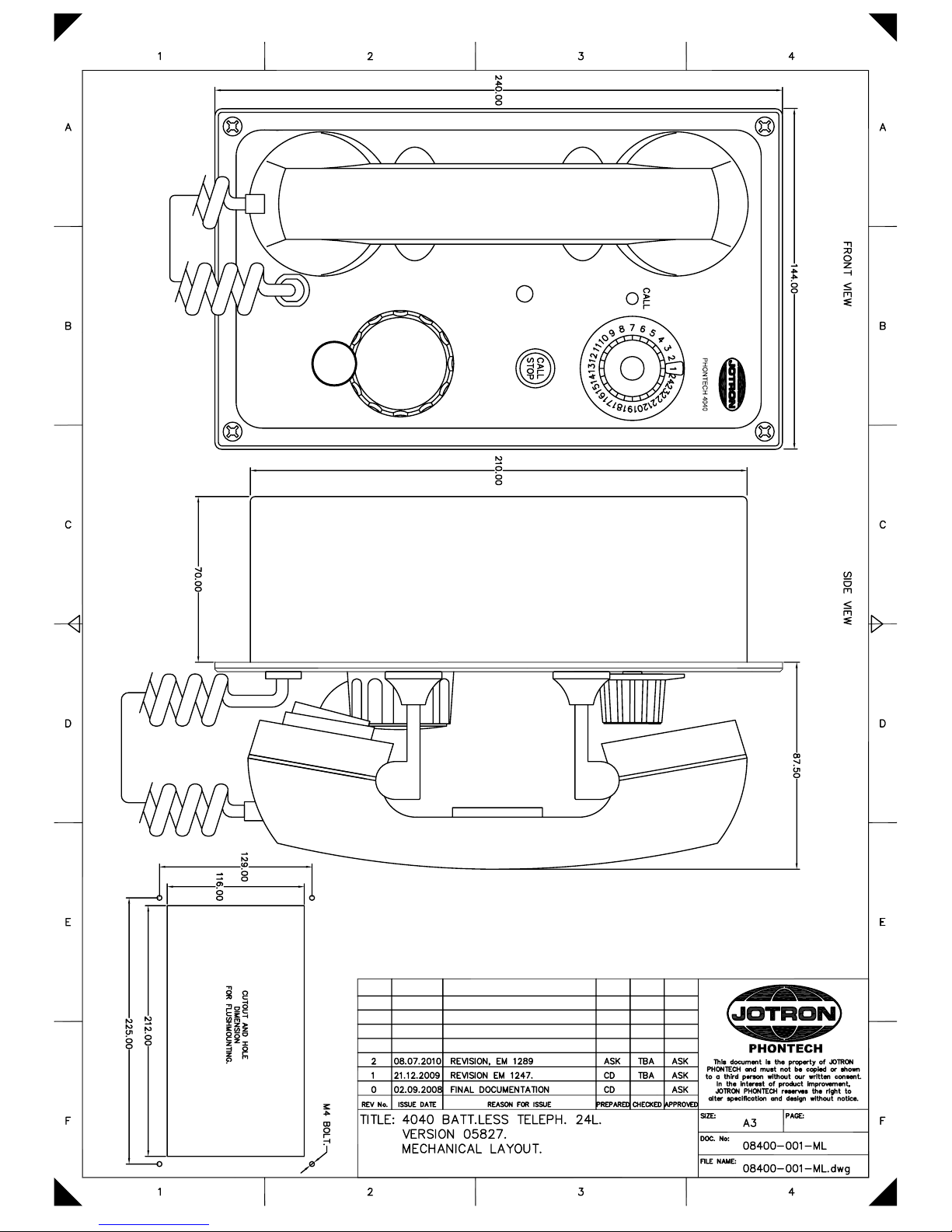
− Mechanical Layout (flush mounted) ……………….……………….. 08400-001-ML .………… 23
− Mechanical Layout (bulkhead mounted) …………..……………….. 08400-001-ML-02 ……… 24
− External Connection ….....…………………………………………… 08400-001-EC ..………… 25
4050, Batteryless Telephone, 1L
− Mechanical Layout (flush mounted) ……………….……………….. 08400-002-ML .………… 26
− Mechanical Layout (bulkhead mounted) …………..……………….. 08400-002-ML-02 ……… 27
− External Connection ….....…………………………………………… 08400-002-EC ..………… 28
4051, Batteryless Telephone w/Amp, 1L
− Mechanical Layout (flush mounted) ……………….……………….. 08400-003-ML .………… 29
− Mechanical Layout (bulkhead mounted) …………..……………….. 08400-003-ML-02 ……… 30
− External Connection ….....…………………………………………… 08400-003-EC ..………… 31
4060, Batteryless Telephone, 12L
− Mechanical Layout (flush mounted) ……………….……………….. 08400-004-ML .………… 32
− Mechanical Layout (bulkhead mounted) …………..……………….. 08400-004-ML-02 ……… 33
− External Connection ….....…………………………………………… 08400-004-EC ..………… 34
4061, Batteryless Telephone w/Amp, 12L
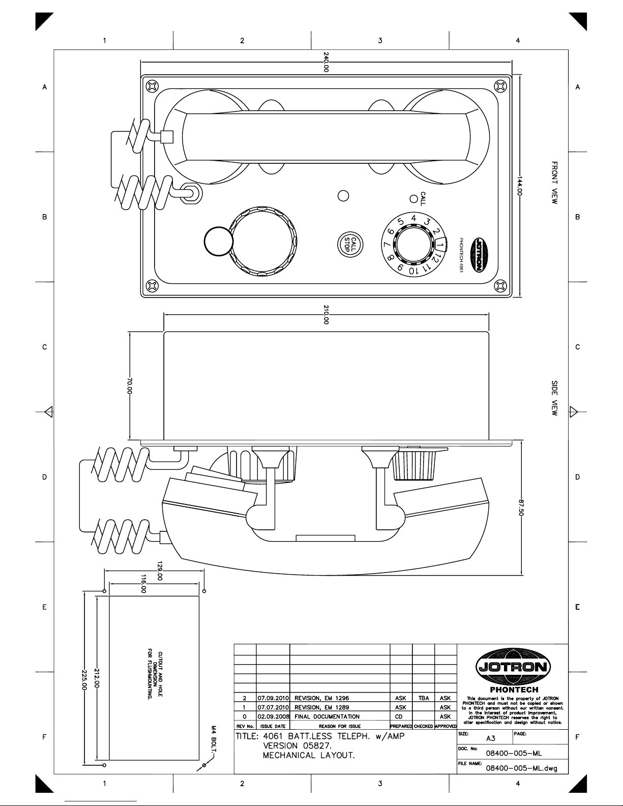
− Mechanical Layout (flush mounted) ……………….……………….. 08400-005-ML .………… 35
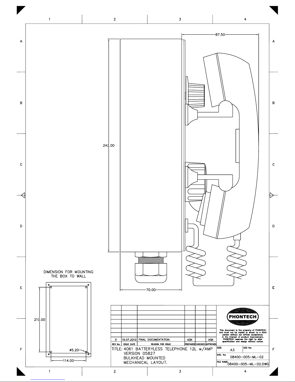
− Mechanical Layout (bulkhead mounted) …………..……………….. 08400-005-ML-02 ……… 36
− External Connection ….....…………………………………………… 08400-005-EC ..………… 37
99400-011, Relay Switch Board for BTS
− Board Layout ………………..................................……………….. 99400-011-LO ...………… 38
− Description …………..……...............................................………….. 99400-011-CA ……......… 39
− Circuit Diagram …............…………………………………………… 99400-011-CD ..………… 40
Amplifier unit, 4000
− Mechanical Layout ……...…………………………………………… 87400-004-ML .………… 41
− External Connection ………....……………….……………………… 87400-004-EC ..………… 42
4018, Headset Plugbox with Call Stop
− Mechanical Layout ……...…………………………………………… 09908-007-ML .………… 43
− External Connection ………....……………….……………………… 09908-007-EC ..………… 44
9000, Relay Unit
− Mechanical Layout ……...…………………………………………… 09908-009-ML .………… 45
− External Connection ………....……………….……………………… 09908-009-EC ..………… 46
Headset with PTT Switch, 0018
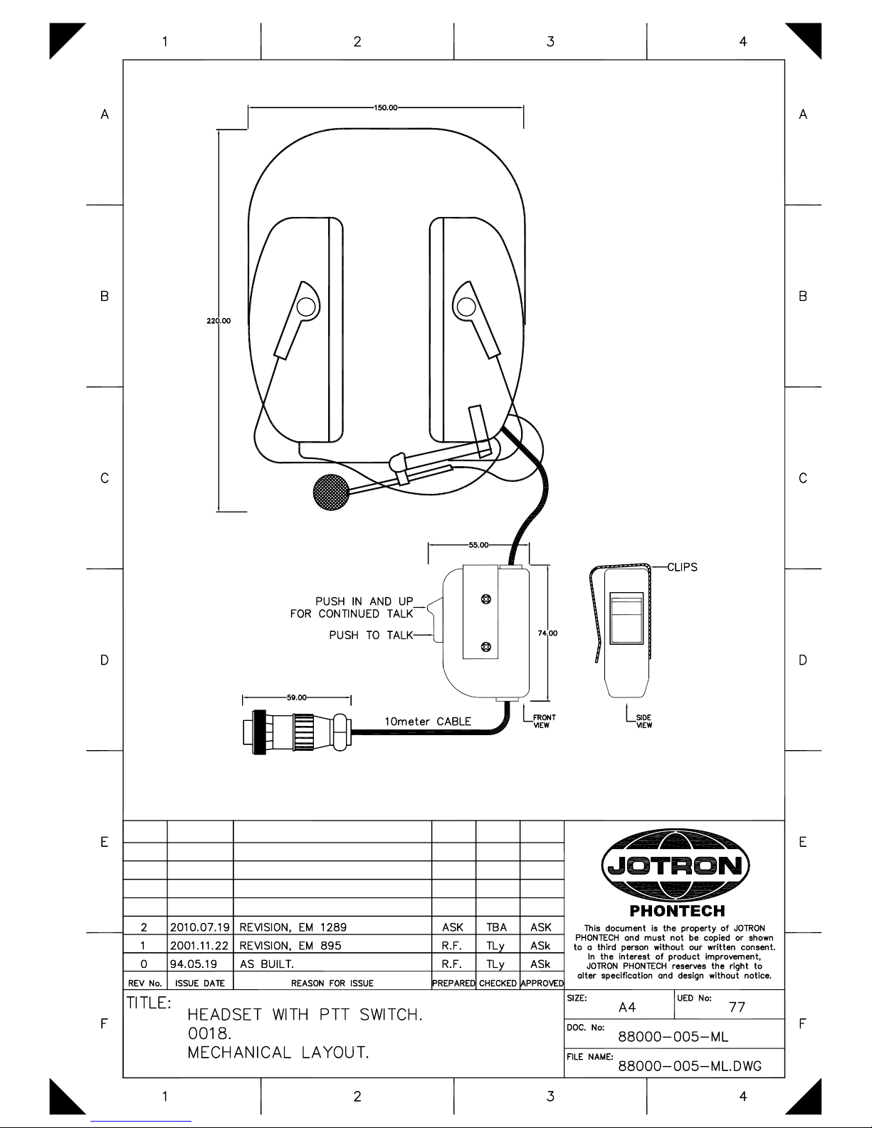
− Mechanical Layout ……...…………………………………………… 88000-005-ML .………… 47
Headset with Chest Switch, 9010
− Mechanical Layout ……...…………………………………………… 00900-002--ML .………… 48
Ver 2010.09
Page 3

Doc.No.: 08400-006-DE
Page 1 of 19
This document is the property of JOTRON
PHONTECH and must not be copied or shown to a
third person without our written consent. In the
interest of product improvement, JOTRON
PHONTECH reserves the right to alter
specification and design without notice.
1 08.07.2010 REVISION, EM 1289 ASK ASK
0 27.10.2008 FINAL DOCUMENTATION CD
REV No: ISSUE DATE REASON FOR ISSUE PREPARED CHECKED APPROVED
TITLE: BATTERYLESS TELEPHONE SYSTEM 4000
DESCRIPTION
SIZE: -- UED no: -DOC no: 08400-006-DE
FILE NAME: 08400-006-DE.doc
BATTERYLESS TELEPHONE SYSTEM 4000
UNITS: 4000 / 4040 / 4050 / 4051 / 4060 / 4061
SYSTEM DESCRIPTION.
Contents:
1. GENERAL DESCRIPTION ............................................................................................................. 3
2. LIST OF TELEPHONE UNITS ....................................................................................................... 4
2.1. 24 LINES BATTERYLESS TELEPHONE, TYPE 4040 ......................................................... 4
2.2. 12 LINES BATTERYLESS TELEPHONE WITH INTEGRATED AMP, TYPE 4061 .......... 5
3. ADDITIONAL EQUIPMENT .......................................................................................................... 6
3.1. AMPLIFIER UNIT, TYPE 4000 ............................................................................................... 6
3.2. RELAY UNIT, TYPE 9000 ...................................................................................................... 7
3.3. PLUGBOX FOR HEADSET WITH CALL STOP, TYPE 4018 .............................................. 7
3.4. HEADSET WITH PTT SWITCH AND PLUG, TYPE 0018 ................................................... 8
3.5. HEADSET WITH PTT SWITCH, TYPE 9010 ........................................................................ 8
3.6. PLUG-IN RELAY MODULE (BRD 99400-011) .................................................................... 9
4. LIST OF FACILITIES ...................................................................................................................... 9
4.1. BATTERYLESS AMPLIFIERT UNIT, TYPE 4000 ............................................................... 9
4.2. 24 LINES BATTERYLESS TELEPHONE 4040 ................................................................... 10
4.3. SINGLE LINE BATTERYLESS TELEPHONE, TYPE 4050 ............................................... 10
4.4. SINGLE LINE BATTERYLESS TELEPHONE WITH AMPLIFIER, TYPE 4051 .............. 10
4.5. 12 LINES BATTERYLESS TELEPHONE, TYPE 4060 ....................................................... 10
5. BASIC MEANS OF OPERATION ................................................................................................ 11
5.1. GENERAL ............................................................................................................................... 11
5.2. MAKE A CALL TO ANOTHER STATION .......................................................................... 11
5.3. ANSWER A CALL FROM ANOTHER STATION ............................................................... 11
5.4. TERMINATE A CONVERSATION ...................................................................................... 11
5.5. HEADSET (TYPE 9010) OPERATION ................................................................................. 12
Handbook page
1/50
Page 4

Doc.No.: 0400-000-DE
Page 2 of 19
5.5.1. Make a call out from the telephone to another station ......................................................... 12
5.5.2. Answer a call from another station ...................................................................................... 12
6. INSTALLATION............................................................................................................................ 13
6.1. SYSTEM CONFIGURATION ................................................................................................ 13
6.2. MOUNTING ............................................................................................................................ 13
6.3. COMPASS SAFE DISTANCE ............................................................................................... 13
6.4. CABLE TERMINATION ....................................................................................................... 13
6.5. CABLE REQUIREMENTS .................................................................................................... 14
6.6. GLANDING ............................................................................................................................ 14
6.7. SCREENING ........................................................................................................................... 14
6.8. MARKING .............................................................................................................................. 14
6.9. FASTENING ........................................................................................................................... 14
6.10. PRESERVATION ................................................................................................................ 14
6.11. VOLUME ADJUSTMENT ................................................................................................. 15
7. TECHNICAL DATA. TELEPHONE UNITS 4040/4050/4051/4060/4061 ................................... 16
8. SINGLE LINE DIAGRAM – SINGLE LINE SYSTEM ............................................................... 17
9. SINGLE LINE DIAGRAM – 12 LINE SYSTEM ......................................................................... 18
10. SINGLE LINE DIAGRAM – 24 LINE SYSTEM ...................................................................... 19
Handbook page
2/50
Page 5

Doc.No.: 08400-006-DE
Page 3 of 19
1. GENERAL DESCRIPTION
The batteryless telephone system is developed and manufactured Jotron Phontech as.
The different modules in the system are designed to meet the need and demand for nonpowered internal (sound powered) emergency communication on ships.
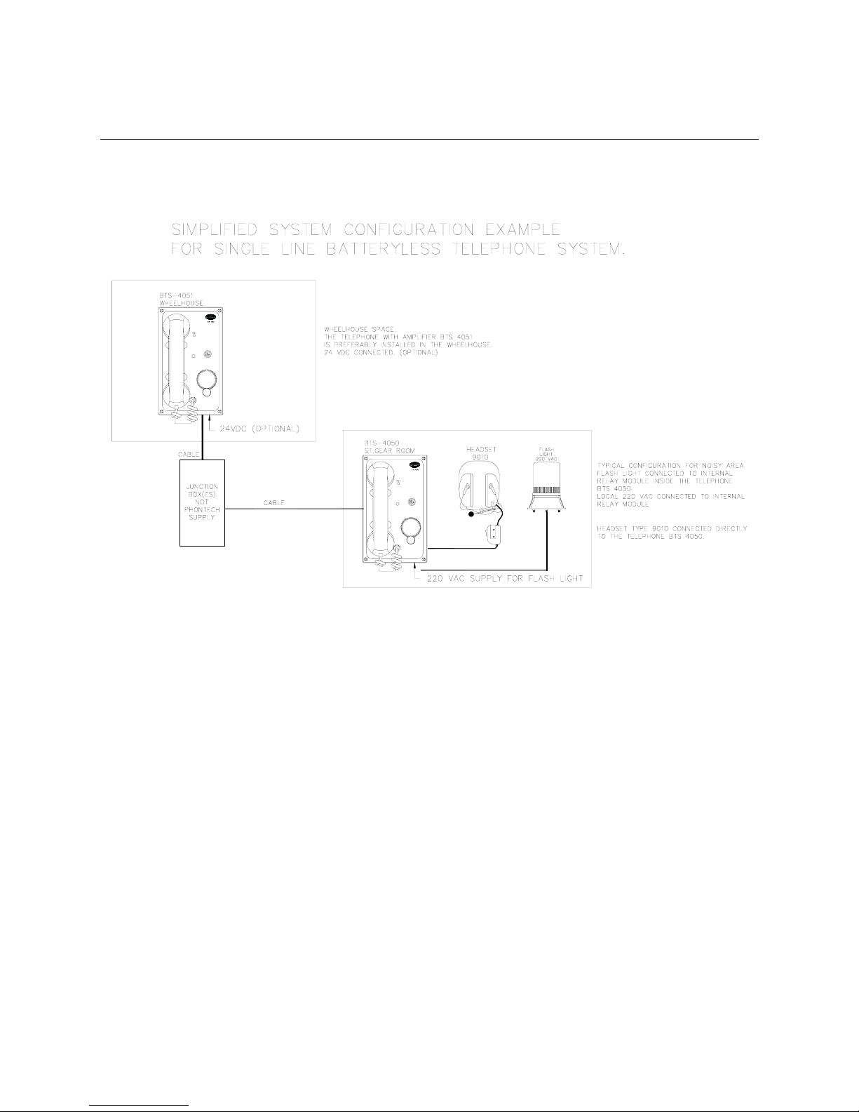
The system is basically divided into three different configurations, the single line system
(4050/4051) for point-to point communication between two stations, like the bridge and the
machinery spaces. The 12 lines system, (4060/4061) for up to 12 stations. And the 24 lines
system (4000/4040) for up to 24 stations.
The compact design provides good installation possibilities, with a minimum space
requirement.
The flush mounting units are adapted to the DIN 144x144 module standard for easy mounting
in the bridge and engine control consoles.
The modules may also be wall mounted; this requires a wall mounting back-box. (Optional)
The different units are prepared for gland mounting, i.e. holes have been fitted for a wide range
of cable glands.
Several additional types of equipment may be connected to the Batteryless Telephone System,
like headset connector boxes, extra headsets, power supplies, external signal devices relay
switch boxes, etc.
Handbook page
3/50
Page 6

Doc.No.: 08400-006-DE
Page 4 of 19
.
2. LIST OF TELEPHONE UNITS
Type BTS 4040. 24 lines batteryless telephone.
Type BTS 4050 Single line batteryless telephone.
Type BTS 4051 Single line batteryless telephone with integrated amplifier
Type BTS 4060 12 lines batteryless telephone.
Type BTS 4061 12 lines batteryless telephone with integrated amplifier
2.1. 24 LINES BATTERYLESS TELEPHONE, TYPE 4040
PHONTECH 4040
Handbook page
4/50
Page 7

Doc.No.: 08400-006-DE
Page 5 of 19
.
2.2. 12 LINES BATTERYLESS TELEPHONE WITH INTEGRATED AMP, TYPE
4061
PHONTECH 4061
Handbook page
5/50
Page 8

Doc.No.: 08400-006-DE
Page 6 of 19
.
3. ADDITIONAL EQUIPMENT
Type BTS 4000. Amplifier unit (separate) for a 4040 / 24 lines system
Type 9000 Relay unit (for additional signal device)
Type 4018 Plugbox for headset with “Call stop”.
Type 0018 Headset with PTT switch and plug. (Connects to 4018)
Type 9010 Headset with PTT switch. (Connects directly to the telephone unit)
BRD 99400-011 Plug-in relay module for external signal device.
Type 4052 Junction box type I (12 ext.)
Type 4053 Junction box type II (8 ext.)
3.1. AMPLIFIER UNIT, TYPE 4000
Handbook page
6/50
Page 9
Doc.No.: 08400-006-DE
Page 7 of 19
.
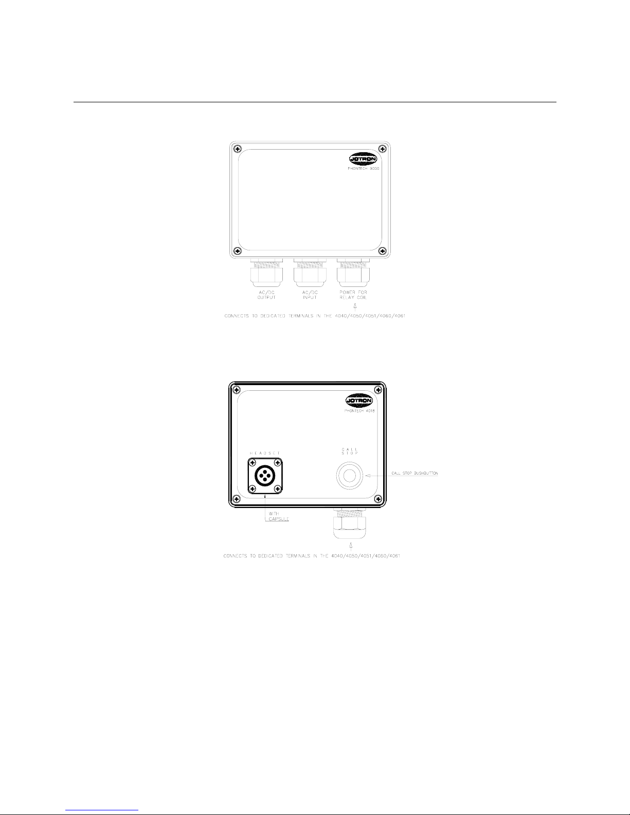
3.2. RELAY UNIT, TYPE 9000
3.3. PLUGBOX FOR HEADSET WITH CALL STOP, TYPE 4018
Handbook page
7/50
Page 10

Doc.No.: 08400-006-DE
Page 8 of 19
.
3.4. HEADSET WITH PTT SWITCH AND PLUG, TYPE 0018
3.5. HEADSET WITH PTT SWITCH, TYPE 9010
9 meter CABLE
Handbook page
8/50
Page 11

Doc.No.: 08400-006-DE
Page 9 of 19
.
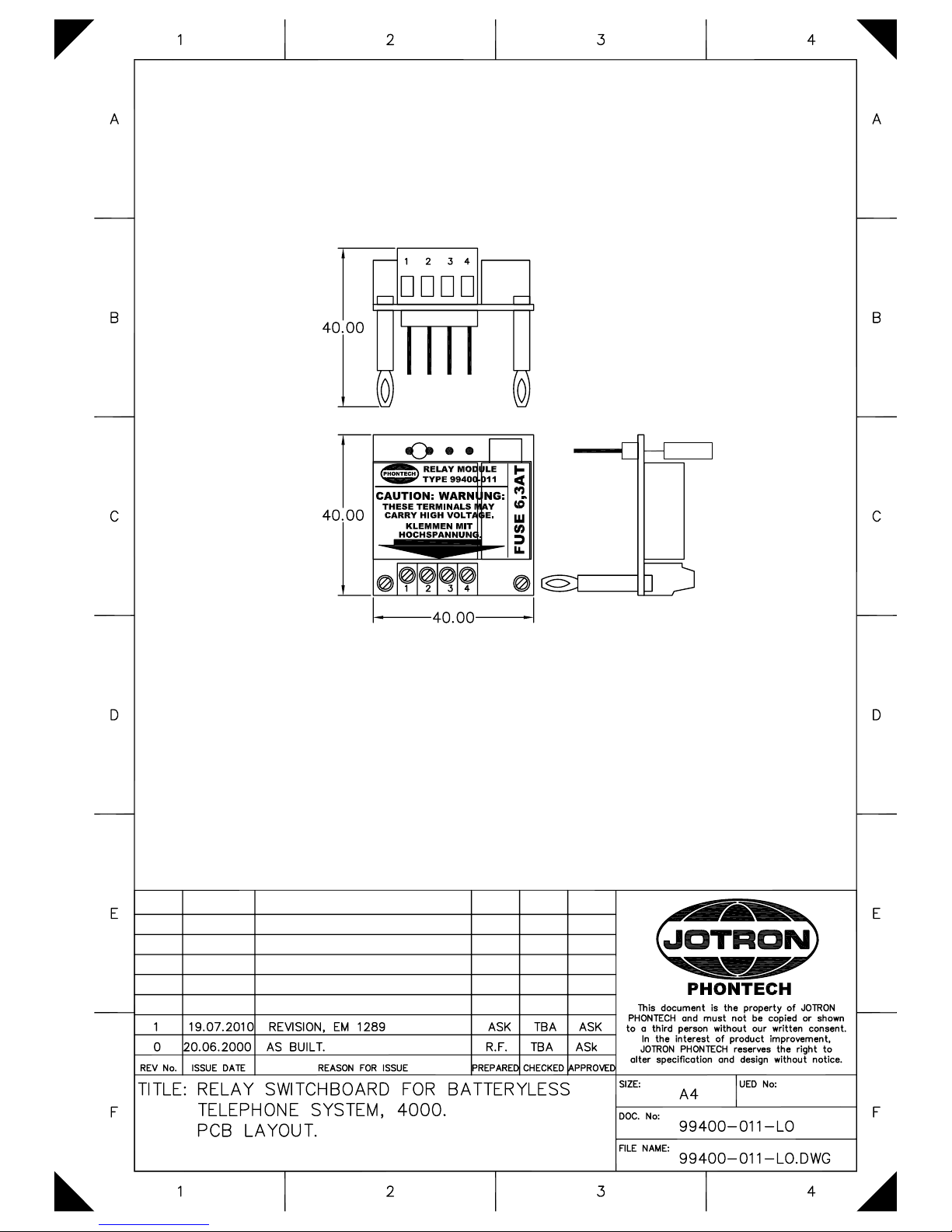
3.6. PLUG-IN RELAY MODULE (BRD 99400-011)
A relay module for activation of external signal device can be installed in the betteryless
telephones: 4040 / 4050 / 4051 / 4060 / 4061
The relay module is to be mounted by the installer. The unit is delivered separately, and is to be
plugged into the appropriate telephone unit.
• Open the backbox on the telephone unit.
• Plug the relay unit into the receptacle on the PCB inside the telephone. Make sure the
connector pins make contact.
• Snap the stand off`s (2pcs) into the holes in the PCB.
• Make the connections according to the installation drawings 99400-017-EC or 99400-018-
EC.
• If DC voltage is used, make sure the polarity is correct. (Indication on the dwgs. 99400-
017-EC and 99400-018-EC)
4. LIST OF FACILITIES
4.1. BATTERYLESS AMPLIFIERT UNIT, TYPE 4000
- Interface for up to 24 batteryless telephones
- Extreme low current drain speech amplifier.
Handbook page
9/50
Page 12

Doc.No.: 08400-006-DE
Page 10 of 19
.
4.2. 24 LINES BATTERYLESS TELEPHONE 4040
- Handset with PTT button.
- Noise cancelling microphone.
- Piezo- electric buzzer for call indication.
- Call led.
- 20 seconds call delay timer. (24 VDC required)
- Call stop button.
- Call line rotary selector switch.
- Back lightning of the line selector and the call stop button. (24 VDC required)
4.3. SINGLE LINE BATTERYLESS TELEPHONE, TYPE 4050
- Handset with PTT button.
- Noise cancelling microphone.
- Piezo- electric buzzer for call indication.
- Call led.
- 20 seconds call delay timer. (24 VDC required)
- Call stop button.
- Back lightning of the call stop button. (24 VDC required)
4.4. SINGLE LINE BATTERYLESS TELEPHONE WITH AMPLIFIER, TYPE 4051
- Handset with PTT button.
- Noise cancelling microphone.
- Piezo- electric buzzer for call indication.
- Call led.
- 20 seconds call delay timer. (24 VDC required)
- Call stop button.
- Back lightning of the call stop button. (24 VDC required)
- Extreme low current drain speech amplifier.
4.5. 12 LINES BATTERYLESS TELEPHONE, TYPE 4060
- Handset with PTT button.
- Noise cancelling microphone.
- Piezo- electric buzzer for call indication.
- Call led.
- 20 seconds call delay timer. (24 VDC required)
- Call stop button.
- Call line rotary selector switch.
- Back lightning of the line selector and the call stop button. (24 VDC required)
Handbook page
10/50
Page 13

Doc.No.: 08400-006-DE
Page 11 of 19
.
4.6. 12 LINES BATTERYLESS TELEPHONE WITH AMPLIFIER, TYPE 4061
- Handset with PTT button.
- Noise cancelling microphone.
- Piezo - electric buzzer for call indication.
- Call led.
- 20 seconds call delay timer. (24 VDC required)
- Call stop button.
- Call line rotary selector switch.
- Back lightning of the line selector and the call stop button. (24 VDC required)
- Extreme low current drain speech amplifier.
5. BASIC MEANS OF OPERATION
5.1. GENERAL
The batteryless telephone system is operated by means of the handset with PTT switch,
the call line selector switch, (not 4050/4051) and the call generator crank.
There is no priority between units in the system and several users can use the system
simultaneously. All users will then join the same conversation/conference call.
The units are equipped with screw terminals for connection of a headset, type 9010.
5.2. MAKE A CALL TO ANOTHER STATION
- Lift the handset. (See illustration next page)
- Select the line by means of the line selector (not applicable to 4050/4051)
- Crank the generator 3-5 turns.
5.3. ANSWER A CALL FROM ANOTHER STATION
- The telephone will sound the call tone and light the call indicator led (red)
- Lift the handset (See illustration next page) and press the PTT button.
Keep the PTT button pressed at all times during conversation.
- Optional headset: Set the PTT switch to ON and answer the call.
- If external power is connected to the system, the call delay timer will keep the call
indicator led lit (green) for about 30 seconds. Press the “CALL STOP” button (on the
telephone or the headset plugbox, type 4018) to turn it off manually before automatic
time out.
- Additional external signal devices will be activated together with the call indicator led.
5.4. TERMINATE A CONVERSATION
- Replace the handset in the holder. (See illustration next page)
Handbook page
11/50
Page 14

Doc.No.: 08400-006-DE
Page 12 of 19
.
5.5. HEADSET (TYPE 9010) OPERATION
5.5.1. Make a call out from the telephone to another station
- Put the headset on, with the microphone close to your mouth.
- Select the line by means of the line selector (not applicable to 4050/4051),
- Crank the generator (on the telephone) 3-5 turns.
- When the call is answered, press the PTT -switch temporary on to talk or push it
in/upwards for locked operation (handsfree).
- After the conversation, release the PTT-switch. From locked position press the button
downwards.
5.5.2. Answer a call from another station
- Put the headset on, with the microphone close to your mouth.
- Press the PTT -switch temporary on to talk or push it in/upwards for locked operation
(handsfree).
- After the conversation, release the PTT-switch. From locked position press the button
downwards.
- Replace the headset to its stowage position
ON/OFF HOOK HANDSET MOTION:
Handbook page
12/50
Page 15

Doc.No.: 08400-006-DE
Page 13 of 19
.
6. INSTALLATION
6.1. SYSTEM CONFIGURATION
The system is to be configured by the installer. Each telephone must be connected to
different “call number” with regards to the Line selector (rotary switch). This is done by
means of a link connection in each telephone.
In a system consisting of 4040 telephones (up to 24 lines) this link is between terminal 29
and the required extension/call number terminal (1-24). Ref drawing 92400-008-EC.
In a 4050/4051 telephone point-to-point configuration the call link is made by means of
connecting terminal 1 of one telephone to terminal 13 (Call input) of the other and vice
versa. Ref drawing 99400-017-EC.
In a 4060/4061 telephone configuration (up to 12 lines) the link is to be connected between
terminal 13 and the desired call number. (1-12). Ref drawing 99400-018-EC.
6.2. MOUNTING
The telephone units (all types) are delivered for flush mounting. Optional wall mounting boxes
are delivered upon request.
Jotron Phontech as highly recommends the use of junction boxes for the external cable
distribution.
Prepared junction boxes, type 4052 and 4053 are available.
The sub-units (4000/4018/9000) are delivered with wall mounting box as standard.
6.3. COMPASS SAFE DISTANCE
Compass type Safe distance
BTS 4000 / 4040 / 4050 /
4051 / 4060 / 4061
Standard 1,7m
Steering
Stand by steering Emergency
0,95m
6.4. CABLE TERMINATION
All terminations must be done according to the External Cabling diagrams (example). Ref
chapter 6.1 above.
Handbook page
13/50
Page 16

Doc.No.: 08400-006-DE
Page 14 of 19
.
6.5. CABLE REQUIREMENTS
All cables used with the Batteryless Telephone System to be of approved ship cable type.
ESPECIALLY IMPORTANT:
! Common outer screen
! Individually twisted pairs
! Recommended minimum conductor area is 0.50 mm²
! All cabling in the batteryless telephone system to be a separate network
! DO NOT COMBINE WITH OTHER CABLES. THIS IS TO PREVENT
DISTURBANCE AND NOISE CAUSED BY INTERFERENCE.
6.6. GLANDING
The cables enter the units by means of cable glands. Where cable glands are not supplied from
the factory, the installer must adapt the glands to the actual cable outer diameter. This is to
obtain the specified ingress protection and cable relief.
6.7. SCREENING
The cable screen must be terminated to the ships GND in the “main unit” (4051/4061). The
cable screen must be connected through the junction box(s) and terminated in terminal 21
(terminal 35 in 4040) or earth stud in all telephones. Ref chapter 6.1 above.
6.8. MARKING
Each cable to be marked with cable number.
Each conductor to be marked with the specific termination number.
Please note that BTS telephones uses plug-able screw terminals as standard. This is to make the
installation and service work as smooth as possible.
6.9. FASTENING
Where applicable, the cables and the conductors shall be strapped to the structure.
6.10. PRESERVATION
Prior to, during, and after completion of the installation the equipment surfaces to be protected
against acid holding fluids, pollution, moist, impacts etc.
Handbook page
14/50
Page 17

Doc.No.: 08400-006-DE
Page 15 of 19
.
This in order to avoid damaged equipment for which Jotron Phontech will void warranty
claims.
6.11. VOLUME ADJUSTMENT
Please note that volume adjustment is preset to a normal environment. It is not possible to make
individual volume adjustments on the telephones, but there is a common volume adjustment for
the whole system.
This is located in the system amplifier either as trimming potentiometer R12 in the 4000 unit or
RV1 in the 4051/4061 units.
R12 POSITION IN THE 4000 UNIT (BRD 87400-001):
Handbook page
15/50
Page 18

Doc.No.: 08400-006-DE
Page 16 of 19
.
RV1 POSITION IN THE 4051/4061 UNITS (BRD 99400-001):
7. TECHNICAL DATA. TELEPHONE UNITS 4040/4050/4051/4060/4061
Dimensions flush mounting:
240 x 144 x 70 mm. (h x w x d)
Cut- out measurement flush mounting:
212 x 116 mm. (h x w)
Dimensions wall mounting wall mounting box included:
242 x 146 x 73 mm. (h x w x d)
Type 4050/51/60/61: add 78 mm to depth for handset.
Weight flush mounted: 1.4 kg.
Weight wall mounted: 1.8 kg.
Operation voltage 24 VDC (optional)
Ingress protection: IP 44.
Technical data for substations etc. see data sheets for each unit.
Handbook page
16/50
Page 19
Doc.No.: 08400-006-DE
Page 17 of 19
.
8. SINGLE LINE DIAGRAM – SINGLE LINE SYSTEM
Handbook page
17/50
Page 20

Doc.No.: 08400-006-DE
Page 18 of 19
.
9. SINGLE LINE DIAGRAM – 12 LINE SYSTEM
S T O P
H E A D S E T
4 0 1 8
C A L L
Handbook page
18/50
Page 21

Doc.No.: 08400-006-DE
Page 19 of 19
.
10. SINGLE LINE DIAGRAM – 24 LINE SYSTEM
S T O P
H E A D S E T
4 0 1 8
C A L L
PHONTECH 4040
PHONTECH 4040
PHONTECH 4040
PHONTECH 4040
PHONTECH 4040
PHONTECH 4040
PHONTECH 4040
Handbook page
19/50
Page 22
Handbook page
20/50
Page 23
Handbook page
21/50
Page 24
Handbook page
22/50
Page 25
Handbook page
23/50
Page 26

Handbook page
24/50
Page 27

Handbook page
25/50
Page 28

Handbook page
26/50
Page 29

Handbook page
27/50
Page 30

Handbook page
28/50
Page 31

Handbook page
29/50
Page 32

Handbook page
30/50
Page 33
Handbook page
31/50
Page 34

Handbook page
32/50
Page 35

Handbook page
33/50
Page 36
Handbook page
34/50
Page 37
Handbook page
35/50
Page 38
Handbook page
36/50
Page 39

Handbook page
37/50
Page 40
Handbook page
38/50
Page 41

Doc.No.: 99400-011-CA
Page 1 of 1
This document is the property of JOTRON
PHONTECH and must not be copied or shown to a
third person without our written consent. In the
interest of product improvement, JOTRON
PHONTECH reserves the right to alter
specification and design without notice.
2 16.07.2010 REVISION, EM 1289 ASK ASK
1 20.08.2009 REVISION, EM 1213 CD
0 09.05.2001 DVM COMPLETION t.ly
REV No: ISSUE DATE REASON FOR ISSUE PREPARED CHECKED APPROVED
TITLE: RELAY SWITCH BOARD FOR BATTERYLESS
SYSTEM
DESCRIPTION
SIZE: -- UED no: M002
DOC no: 99400-011-CA
FILE NAME: 99400-011-CA.doc
RELAY SWITCH BOARD FOR BATTERYLESS SYSTEM
99400-011
DESCRIPTION
The Batteryless Telephone Board 99400-001 is designed and produced by Jotron Phontech AS.
The board is a plug-in module supporting switching facility for external signal device in the batteryless
telephone system.
The Relay board is compatible with BTS telephone types 4040 (Ver 05827), 4050, 4051, 4060 and
4061.
Switching capacity:
24 VDC: 150 VA
115 VAC: 700 VA
220 VAC: 1500 VA
Operation voltage:
Relay coil: 24 VDC
Handbook page
39/50
Page 42

Handbook page
40/50
Page 43

Handbook page
41/50
Page 44

Handbook page
42/50
Page 45

Handbook page
43/50
Page 46

Handbook page
44/50
Page 47

Handbook page
45/50
Page 48

Handbook page
46/50
Page 49
Handbook page
47/50
Page 50

Handbook page
48/50
Page 51

Bilde omslag bak.indd 1 16.06.2009 08:45:31
Handbook page
49/50
Page 52
www.jotron.com
Generell bakside.indd 1 30.01.2009 12:54:47
Handbook page
50/50
 Loading...