

Page 1
www.jotron.com
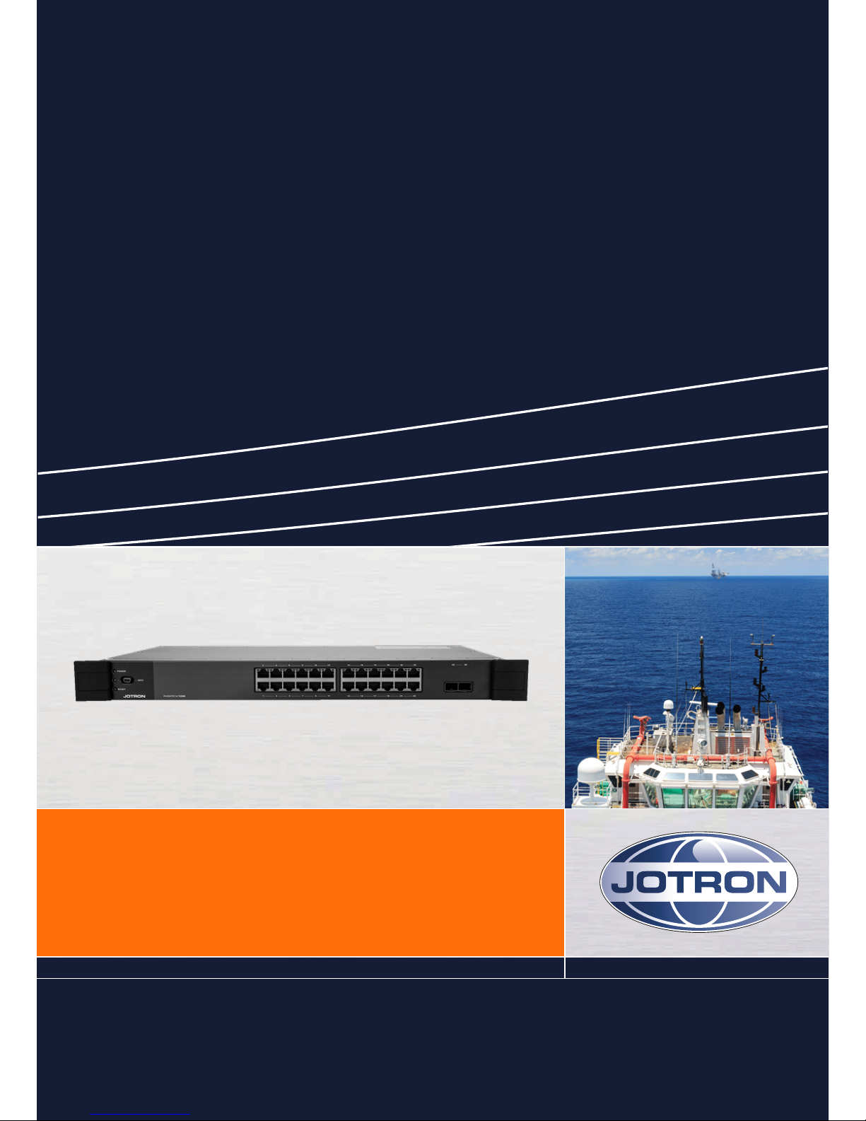
USER MANUAL
Phontech 7200
Page 2

Page - 2 -
Table of contents
1 List of figures 5
2 Abbreviations 6
3 General 8
4 Standards 9
5 Product description 10
5.1 Product image Phontech 7200, 24 PoE Ethernet GBit Switch 11
6 System description 12
6.1 Major functions 12
6.1.1 Management 12
6.1.2 Monitoring and troubleshooting 13
6.1.3 Network configuration 13
6.1.4 Advanced security 13
6.1.5 Power over Ethernet (PoE) 13
6.1.6 Quality of Service (QoS) 13
6.1.7 Layer 2 switching 13
6.1.8 Layer 3 switching 14
6.1.9 Power savings 14
6.2 Mechanical layout 14
6.3 Electrical connections 15
7 Technical specifications 17
7.1 Product specification 17
8 Installation 18
8.1 Glands 18
8.2 Punch block terminals 18
8.3 Ferruling 18
8.4 Marking 18
8.5 Fastening 19
8.6 Preservation 19
8.7 Screen connection 19
Page 3

Page - 3 -
8.8 Cable requirements for power lines 19
8.9 Cable requirements for Ethernet 20
8.10 Using 802.3AF-2003 PoE for VoIP telephones 20
9 Configuration 22
9.1 Command line interface (CLI) 22
9.1.1 CLI requirements 22
9.1.2 Starting the command line interface 22
9.1.3 Setting up the IP address 23
9.1.4 Changing the password 27
9.1.5 Command line help 28
9.1.6 Reloading the defaults 30
9.2 Web interface 31
9.2.1 Web interface requirements 31
9.2.2 Starting the web interface 32
9.2.3 Changing the IP address 33
9.2.4 Changing the system password 34
9.2.5 Help system 35
9.2.6 System information 36
9.2.7 Firmware update 37
9.2.8 System log 39
9.2.9 Reverting to defaults 40
10 Operation instructions 41
10.1 Front panel 41
10.1.1 Ethernet ports 41
10.1.2 SFP slots 41
10.1.3 Service port 41
10.1.4 LEDindicators 41
10.1.5 Reset button 42
10.1.6 Restoring the default settings 42
11 Maintenance 43
Page 4

Page - 4 -
12 Test and maintenance records 44
13 Warranty 45
13.1 Warranty claims 45
13.2 Service 46
13.3 Service agents 46
14 Spare parts 47
15 Recycling and disposal 48
Page 5

Page - 5 -
1 List of figures
Figure 1 Phontech 7200, 24 PoE Ethernet GBit Switch - product image 11
Figure 2 Phontech 7200, 24 PoE Ethernet GBit Switch - front view 14
Figure 3 Phontech 7200, 24 PoE Ethernet GBit Switch - rear view 14
Figure 4 Phontech 7200, 24 PoE Ethernet GBit Switch - top view 15
Figure 5 Phontech 7200, 24 PoE Ethernet GBit Switch - rear view AC/DC version 15
Figure 6 Phontech 7200, 24 PoE Ethernet GBit Switch - rear view AC/AC version 16
Figure 7 Phontech 7200, 24 PoE Ethernet GBit Switch - front view - mini USB connector 16
Figure 8 Phontech 7200, 24 PoE Ethernet GBit Switch - powering VoIP phones 21
Figure 9 Starting the command line interface - log in screen 23
Figure 10 Configuring the static IP 24
Figure 11 Verifying the static IP 25
Figure 12 Configuring the dynamic IP 26
Figure 13 Verifying the dynamic IP 27
Figure 14 Changing the password 28
Figure 15 List of help menu commands 29
Figure 16 Description of the help system 30
Figure 17 Reloading the defaults 31
Figure 18 Authentication prompt 32
Figure 19 Welcome screen 32
Figure 20 IP Interfaces table in the IP Configuration screen 33
Figure 21 Saving from the menu bar 34
Figure 22 System password configuration page 35
Figure 23 Example: IP configuration help page 36
Figure 24 System information page 37
Figure 25 Firmware software upload page 38
Figure 26 Firmware update status page 39
Figure 27 System log information 40
Figure 28 Phontech 7200, 24 PoE Ethernet GBit Switch Front panel 41
Page 6

Page - 6 -
2 Abbreviations
AC/DC Alternating current/Direct current
ACL Access Control List
CLI Command Line Interface
CMOS Complementary Metal-Oxide Semiconductor
DC Direct current (input)
DHCP Dynamic Host Configuration Protocol
DWRR Deficit Weighted Round Robin
LACP. Link Aggregation (control protocol).
EEE Energy Efficient Ethernet
EIA Electronic Industries Alliance
EMC Electromagnetic compatibility
HTTP Hypertext Transfer Protocol
IC Integrated circuit (system)
IEC International Electrotechnical Commission
IEEE Institute of Electrical and Electronics Engineers
IP Internet protocol (address)
LACP Link Aggregation
LAN Local area network
LED Light emitting diode
LLDP Link Layer Discovery Protocol
MAC Media Access Control
MHz Megahertz
MSA Multi-source agreement
PD PoE powered device
PHY Physical layer (connects link layer device)
PoE Power over Ethernet
QCL QoS Control Lists
QoS Quality of service
RMA Return Material Authorization number
RSTP Rapid spanning tree protocol
SNMP Simple Network Management Protocol
SQP Strict Priority
SFP Small form-factor pluggable
STP Spanning tree protocol/Shielded twisted pair
Page 7

Page - 7 -
TIA Telecommunications Industry Association
USB Universal Serial Bus
UTP Unshielded twisted pair
VAC Volts Alternating Current
VDC Volts of direct current
VoIP Voice over Internet Protocol
VLAN Virtual Local Area Network
WP Weatherproof (unit)
Page 8
Page - 8 -
3 General
Jotron develops and manufactures professional and state of the art products and communication systems for usage
in air, on land and at sea. Jotron supplies products and services that comply with the latest applicable standards. The
use of modern test instrumentation and detailed test procedures ensures that you are supplied with quality products.
Copies of all Jotron documentation can be downloaded from our website: www.jotron.com.
All information contained within this manual has been verified and is correct, however, no responsibility is assumed by
Jotron for inaccuracy. Jotron reserves the right to make changes to any product(s) or module(s) described herein to
improve reliability, function or design, without further notice.
The following four symbols are in use throughout this manual:
This symbol is used to highlight information.
This symbol is used to draw attention to important details.
This symbol is used to highlight information that if not followed can result in damage to a product or
equipment.
This symbol is used to highlight information that if not followed can result in personal injury or bodily
harm.
Jotron is not liable for consequential or special damages and cannot be held responsible for any
damages or injury arising either directly or indirectly due to an error or omission of information,
misuse of a product, breach of procedures, or for failure of any specific component or other part of
the equipment.
Page 9
Page - 9 -
4 Standards
The Phontech 7200, 24 PoE Ethernet GBit Switch has been verified, tested and meets the following product
standards:
EMC: EN60945 (2002), EN61000-4-2,EN61000-4-3, EN61000-4-4, EN61000-4-5,
EN61000-4-6
Environmental: EN60945 (2002), EN60068-2-1, EN60068-2-2, EN60068-2-6, EN60068-2-
30, EN60068-2-52
Ingress protection: IEC 60529
Certification for marine
computers:
IEC 60945
All statements of conformity are available at: www.jotron.com
Page 10
Page - 10 -
5 Product description
The Phontech 7200, 24 PoE Ethernet GBit Switch includes 24 gigabit Ethernet and 2 gigabit small form-facrtor
pluggable (SFP) ports for the fiber connectivity, there are in total 26 ports. The switch is fully manageable through the
web and command line interface.
The main features include:
• Virtual Local Area Network (VLAN)
• Quality of Service (QoS)
• Media Access Control (MAC)
• Link Layer Discovery Protocol (LLDP)
• Spanning Tree
• Power over Ethernet (PoE)
• Network security
• Power saving
• Port management
The Phontech 7200, 24 PoE Ethernet GBit Switch is a computer networking device that connects devices together
on a computer network, by using packet switching to receive, process and forward data to the destination device.
The Phontech 7200, 24 PoE Ethernet GBit Switch is rack mountable.
Part numbers:
• 86725 - Phontech 7200, 24 PoE Ethernet GBit Switch, 24 PoE Eth. GBit Switch, AC/AC
• 87785 - Phontech 7200, 24 PoE Ethernet GBit Switch, 24 PoE Eth. GBit Switch, AC/DC
This equipment contains CMOS integrated circuits. Observe precautions for handling electrostatic
sensitive device. Electrostatic discharge (ESD) may damage this equipment.
Page 11

Page - 11 -
5.1 Product image Phontech 7200, 24 PoE Ethernet GBit
Switch
Figure 1 Phontech 7200, 24 PoE Ethernet GBit Switch - product image
Page 12

Page - 12 -
6 System description
The Phontech 7200, 24 PoE Ethernet GBit Switch has 2 internal power supplies. One serves as the main power source
and the other as a back up power source. There are 2 power input configurations, AC/AC and AC/DC. The unit also
includes a built-in power supply voltage measurement circuit for monitoring purposes. The measurements are
available both on the web and CLI interface.
For best power reduction results the Phontech 7200, 24 PoE Ethernet GBit Switch should be implemented with an
EEE 802.3az power saving option, which automatically turns off the port when there is low to no traffic utilization.
This unit supports IEEE 802.3af (PoE) and IEEE 802.3at (PoE+) on all 24 gigabit Ethernet (GbE) ports. The PoE system
is capable of delivering up to 150 watts of power. The delivered power is managed and monitored per each port.
There are 3 modes for configuring power reservation by the ports (PDs):
1. Power allocation per port.
2. Power according to class.
3. Power reserved by exchanging PoE information using Link Layer Discovery Protocol (LLDP) protocol.
The system description of the Phontech 7200, 24 PoE Ethernet GBit Switch includes details regarding each of the
major functions.
6.1 Major functions
The major functions of the Phontech 7200, 24 PoE Ethernet GBit Switch are as follows:
• Management
• Monitoring and troubleshooting
• Network configuration
• Advanced security
• PoE
• QoS
• Layer 2 switching
• Layer 3 switching
• Power saving
6.1.1 Management
• Command line interface
• Web interface
• Software upload through web
• Configuration download and upload through web
• DHCP client
Page 13

Page - 13 -
• SNMPv1/v2C/v3 Agent
6.1.2 Monitoring and troubleshooting
• Remote server logging using Syslog.
• Local in the flash and ram logging.
• Port based mirroring. The switch system can be configured to mirror frames from multiple ports to a mirror port.
Both incoming (source) and outgoing (destination) frames can be mirrored to the mirror port.
6.1.3 Network configuration
• Auto-negotiating 10/100/1000 ports automatically configure port speed and duplex setting.
• Auto MDI/MDIX crossover detection feature for all three speeds on the twisted pair cable.
• IEEE 802.1AB LLDP for automated device discovery.
6.1.4 Advanced security
• Web and CLI authentication.
• RADIUS centralized access, authorization and accounting management.
• Port based IEEE 802.1X and MAC based authentication system and port settings.
• Access management filtering IP address. Maximum number of entries is 16. Access from HTTP, SNMP interface
if the host IP address matches the IP address range provided in the table.
• ACLs (up to 256) for filtering, policing and port copy.
6.1.5 Power over Ethernet (PoE)
• Support for IEEE 802.3af (PoE) or IEEE 802.3at (PoE+) compliant powered device.
• Power reservation by exchanging PoE information using the LLDP protocol.
• Configurable per port PoE mode, priority and maximum power limits.
6.1.6 Quality of Service (QoS)
• Priority queues: 8 hardware based queues per port for flexible QoS management
• Configurable scheduling algorithm: Strict Priority (SQP)
• Basic QoS classification: using QCL (QoS Control Lists)
• Bandwidth management: ingress rate limiting; egress rate shaping per port
• Storm control: unicast, multicast and a broadcast storm rate control
6.1.7 Layer 2 switching
• IEEE 802.1D Bridge, auto address learning/aging and MAC addresses (static) (up to 8000 MACs).
Page 14
Page - 14 -
• IEEE 802.1Q Virtual LAN (up to 4000 VLANs)
• Private VLAN (static)
• VLAN trunking
• Loop guard
• IEEE 802.3ad Link Aggregation Control Protocol (LACP) and supports static aggregation
• IEEE 802.1D STP and IEEE 802.1w Rapid Spanning Tree Protocol (RSTP)
• IGMPv2 snooping
6.1.8 Layer 3 switching
• IPv4 Unicast: static routing (up to 8 IPv4 interfaces and 32 IPv4 static routes)
6.1.9 Power savings
Energy Efficient Ethernet 802.3az: Low or no traffic utilization reduces power consumption.
LEDs intensity configuration: Lowering the intensity reduces power consumption.
PerfectReach: Power savings depend on the cable length.
Power savings depend on the port link.
Powering down the ports if the temperature gets too high reduces power
consumption.
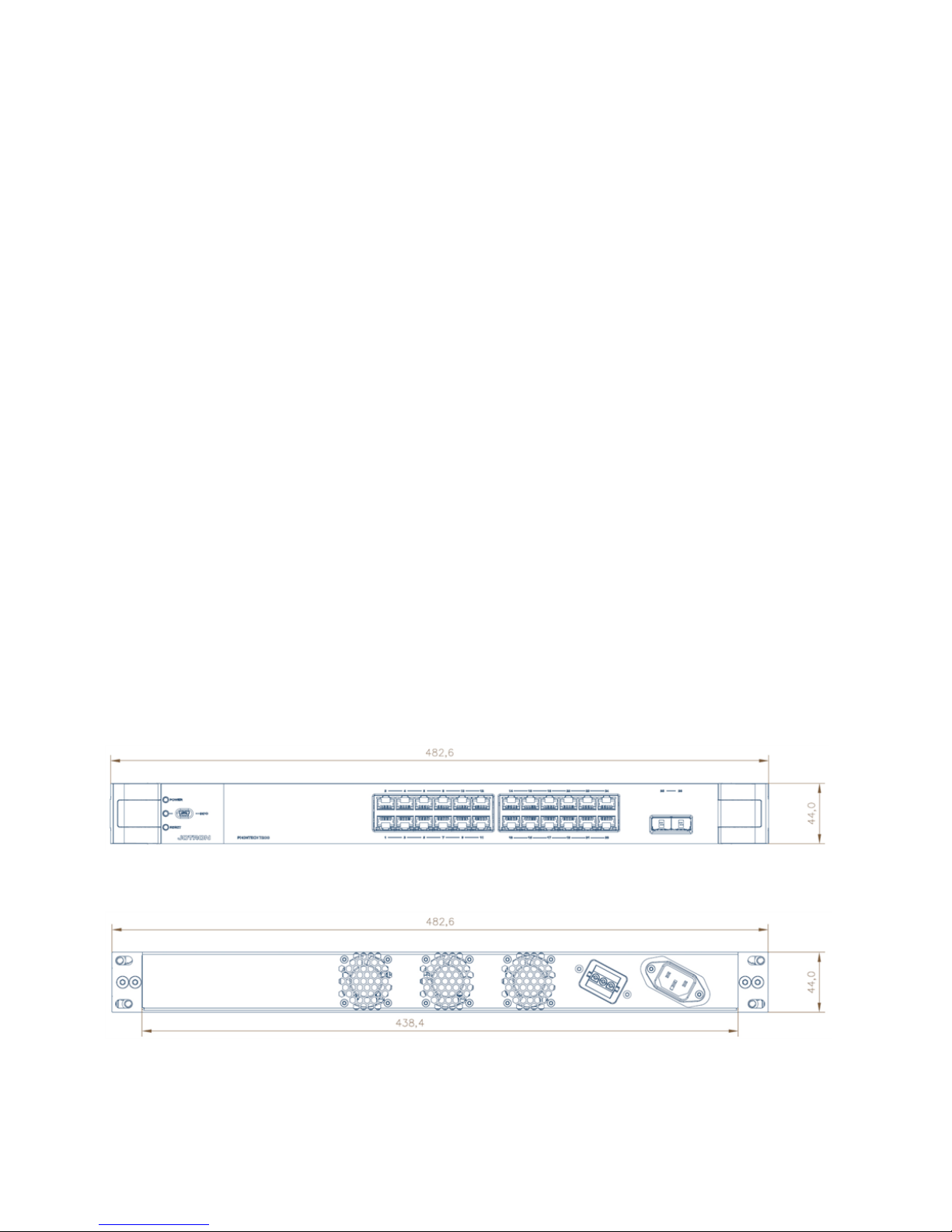
6.2 Mechanical layout
Phontech 7200, 24 PoE Ethernet GBit Switch is a standard 19" rack mountable product, that fits in all industry
standard 19" cabinets.
Figure 2 Phontech 7200, 24 PoE Ethernet GBit Switch - front view
Figure 3 Phontech 7200, 24 PoE Ethernet GBit Switch - rear view
Page 15
Page - 15 -
Figure 4 Phontech 7200, 24 PoE Ethernet GBit Switch - top view
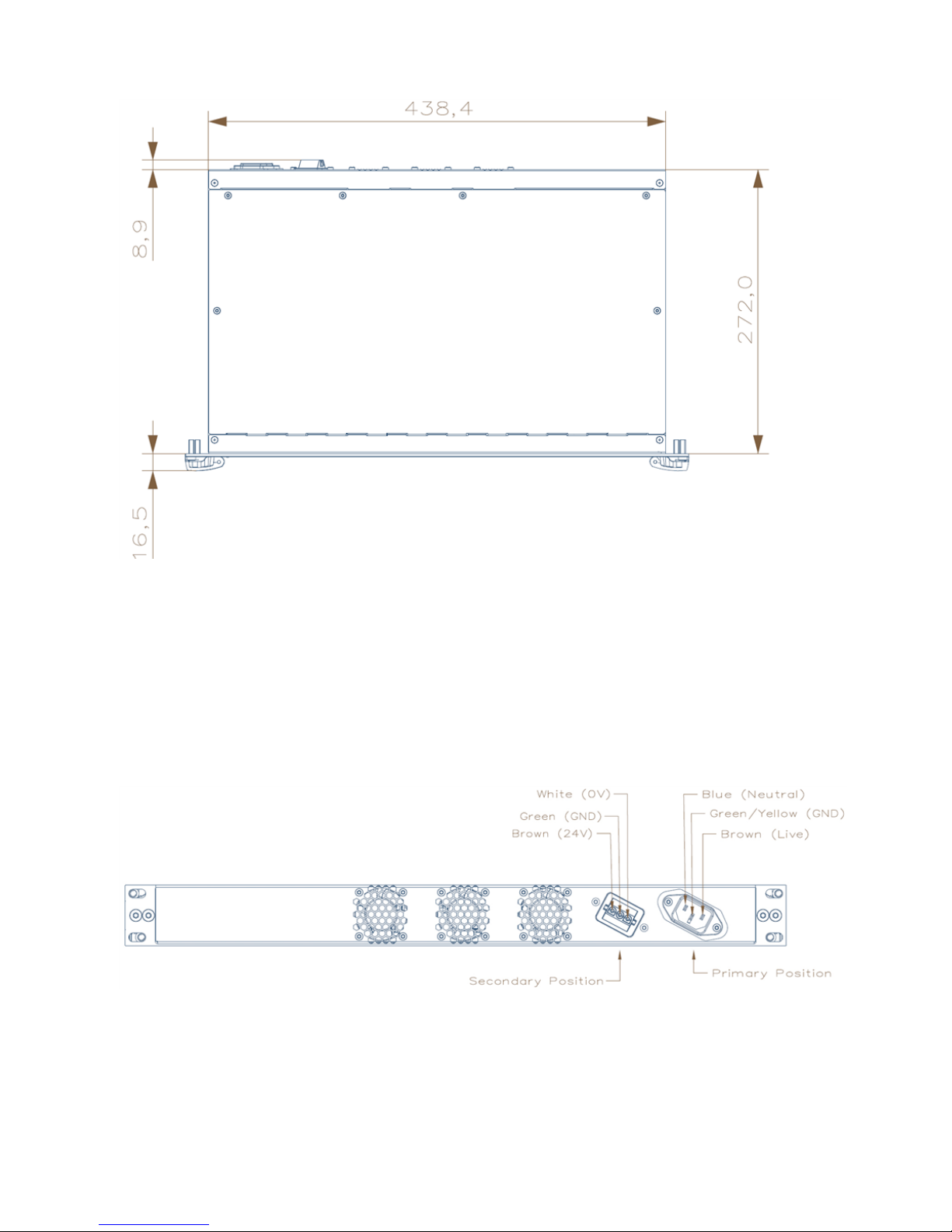
6.3 Electrical connections
Phontech 7200, 24 PoE Ethernet GBit Switch has 24 RJ-45 connectors, 2 slots for pluggable SFP modules and a
USB connector in the front. The back panel contains 2 power input connectors, one for the primary and another for
the secondary power sources. Depending on the Phontech 7200, 24 PoE Ethernet GBit Switch version, the power
input can be AC/DC or AC/AC.
Figure 5 Phontech 7200, 24 PoE Ethernet GBit Switch - rear view AC/DC version
Page 16

Page - 16 -
Figure 6 Phontech 7200, 24 PoE Ethernet GBit Switch - rear view AC/AC version
Figure 7 Phontech 7200, 24 PoE Ethernet GBit Switch - front view - mini USB connector
Page 17

Page - 17 -
7 Technical specifications
7.1 Product specification
Supply voltage: Universal AC input (90-250VAC)
DC input, 24V Nominal (20-36V)
Maximum power consumption: 225 W
System power: 30 W
PoE power budget: 150 W
Dimensions (W/H/D): 440mm/44 mm/290mm (The width is 483mm including front mounting
brackets)
Weight: 3.9 kg
Temperature operating: -15 to +55 °C
Temperature storage: -40 to +70 °C
Humidity: 93% @ +40 °C
Ingress protection: IP 22 (rack mounting)
Compass safe distance >1.7m
Interfaces: 24 RJ45 gigabit ports, 2 gigabit SFP ports, serial service port
Page 18

Page - 18 -
8 Installation
An installation should be properly outlined in detail prior to commencement, consider the following:
• Cables should be listed within a cable plan, including the number of pairs etc.
• Location of each unit in the communication system should be identified, ensuring maximum performance and
user availability.
• Power supply connections must also be taken into consideration.
Jotron strongly recommends the use of junction boxes for the external cable distribution.
8.1 Glands
All cables enter the WP units by means of cable glands.
If cable glands are not included, the individual completing the installation must adapt the glands to
the actual size of the outer cable diameter in order to obtain the specified ingress protection.
8.2 Punch block terminals
When terminating cables in the punch block terminals, ensure you use the correct tool.
8.3 Ferruling
The conducts should be ferruled prior to termination when using cage terminals.
8.4 Marking
• Mark all cables with a cable number.
• Mark all conductors with a termination number.
Page 19

Page - 19 -
Generally, Jotron uses pluggable screw terminals, these are durable and both easy to install and
service.
8.5 Fastening
All cables and conductors should be clamped to the structure with cable ties.
8.6 Preservation
Prior to, during and after the installation is complete the equipment surfaces are to be protected against acid holding
fluids, pollution, moisture and impacts.
Failure to perform preservation protection of the equipment can result in equipment damages and
will void your Jotron warranty.
8.7 Screen connection
For maximum performance after installation, it is necessary to terminate the cables and ground the screens.
8.8 Cable requirements for power lines
Ensure that the cable used is approved in accordance with Jotron specification.
Power cable should be individually twisted pair and the minimum conductor size must be 1 mm2.
To prevent disturbance and noise caused by interference, do not combine different systems in the
same cable.
Page 20

Page - 20 -
8.9 Cable requirements for Ethernet
Ensure that the Ehternet cable to be used has a specification category of minimum shielded Cat 6.
The maximum length of each segment must be less than 100 m.
Jotron recommends using the TIA/EIA-568-B.1-2001 termination scheme.
8.10 Using 802.3AF-2003 PoE for VoIP telephones
Power over Ethernet (PoE) allows supporting units to replace the usual wall wart power supplies that are commonly
used for most electrical products. Phontech 7200, 24 PoE Ethernet GBit Switch is a PoE capable switch, the end
point must support the PoE.
The length of the cabling between the two must not exceed 100 meters as per 802.3af-2003.
If the cable lengths need to be greater than 100 meters then it is recommended you do the
following:
• Distribute one or more of these switches closer to the end point.
• Use a PoE capable repeater or a PoE injector close to the end point.
Page 21

Page - 21 -
Figure 8 Phontech 7200, 24 PoE Ethernet GBit Switch - powering VoIP phones
Page 22

Page - 22 -
9 Configuration
9.1 Command line interface (CLI)
The configuration and functionality of the service port otherwise known as, the command line interface (CLI) on the
Phontech 7200, 24 PoE Ethernet GBit Switch is described in detail below.
9.1.1 CLI requirements
The Phontech 7200, 24 PoE Ethernet GBit Switch command line interface (CLI) is accessible on the serial console
and requires the following:
• Windows XP SP3, Windows Vista SP1, Windows 7 (or a newer version)
• Terminal program
• USB cable with mini B plug
• Serial port driver installed
Drivers for Windows, MAC OS and Linux are available at the FTDI chip website (www.ftdichip.com under Drivers, VCP Drivers)
When starting from a Windows Vista version, the drivers are automatically installed.
Jotron recommends one of the following terminal programs:
Tera Term or PuTTY
9.1.2 Starting the command line interface
Prior to getting started ensure the following:
• The device is turned on and has a functioning connection.
• A mini B USB plug is connected to the service port in the front panel.
• The computer is running a terminal program on Windows.
• The serial ports are set to 115200 bps, no parity, 8 data bits, 1 stop bit and no flow control.
To start the command line interface do the following:
1. Power up the LAN switch.
2. Enter the default user name (admin) and password (unless you have reset this). By default a password is not
required.
Page 23

Page - 23 -
3. Click Enter when ready.
Figure 9 Starting the command line interface - log in screen
9.1.3 Setting up the IP address
To configure the static IP, do the following:
1. Go into the configuration mode.
2. Input and execute the configuration commands.
3. Exit the configuration mode.
Page 24

Page - 24 -
Figure 10 Configuring the static IP
Once configuration is complete, do the following:
1. Verify the static IP address is set up correctly.
2. Save to flash.
Page 25

Page - 25 -
Figure 11 Verifying the static IP
To configure the dynamic IP, do the following:
1. Go into the configuration mode.
2. Input and execute the configuration commands.
3. Exit the configuration mode.
Page 26

Page - 26 -
Figure 12 Configuring the dynamic IP
Once configuration is complete, do the following:
1. Verify the dynamic IP address is set up correctly.
2. Save to flash.
Page 27

Page - 27 -
Figure 13 Verifying the dynamic IP
9.1.4 Changing the password
To change the password, do the following:
1. Enter the command lines.
2. Save to a non-volatile flash memory.
Page 28

Page - 28 -
Figure 14 Changing the password
9.1.5 Command line help
The command line interface has a built in help menu. Use a question mark (?) to call up the help menu.
Page 29

Page - 29 -
Figure 15 List of help menu commands
For a description of the help system, type the word help at the # prompt.
Page 30

Page - 30 -
Figure 16 Description of the help system
9.1.6 Reloading the defaults
There are two options to revert the Phontech 7200, 24 PoE Ethernet GBit Switch back to the default setup, do one
of the following:
1. Enter the command line option, reload defaults
This removes all configuration.
2. Enter the command line option , reload defaults keep-ip.
This will keep the most relevant part of the VLAN 1 IP set up in order to maintain management
connectivity.
Page 31

Page - 31 -
Figure 17 Reloading the defaults
9.2 Web interface
9.2.1 Web interface requirements
The Phontech 7200, 24 PoE Ethernet GBit Switch web configuration interface requires the following:
• Windows XP SP3, Windows Vista SP1, Windows 7 (or a newer version)
• Web browser
• Wired network connection
Jotron recommends one of the following web browsers:
Firefox, Chrome, Safari or Opera
Page 32

Page - 32 -
9.2.2 Starting the web interface
The web interface can be reached through any web browser. First, you must locate the address of the Phontech 7200,
24 PoE Ethernet GBit Switch that is currently configured. The default IP address is: 172.30.0.1/16. The IP address is
found in the command line interface.
Enter the IP address into your web browser to access the web interface. You will be required to login with a user name
and password. The default user name is admin and the password field should be left blank.
Figure 18 Authentication prompt
If the correct user name and password are entered, you will be directed to the web interface welcome screen.
Figure 19 Welcome screen
Page 33

Page - 33 -
9.2.3 Changing the IP address
The IP address is changed in the IP interfaces table.
Figure 20 IP Interfaces table in the IP Configuration screen
After making any changes, it is necessary to save them.
When you click the SAVE button, it only saves configuration data in RAM, therefore, after a reset any
configuration data will be lost.
To save your configuration in a non-volatile flash memory, do the following:
1. From the menu bar, select Maintenance.
2. From the drop down list, select Configuration.
3. From the drop down list, select Save startup-config.
Page 34

Page - 34 -
4. Click the Save Configuration button.
These steps must be completed after every configuration change.
Figure 21 Saving from the menu bar
9.2.4 Changing the system password
A system password is required to access a web page or to log in from CLI.
To change the system password, do the following:
1. From the menu bar, select Configuration.
2. From the drop down list, select Security.
3. From the drop down list, select Switch.
4. From the drop down list, select Password.
5. Enter the old password (leave field blank if no prior password), then enter a new password twice.
6. Click the Save button.
Page 35

Page - 35 -
7. Save your configuration in a non-volatile flash memory.
Figure 22 System password configuration page
9.2.5 Help system
The web configuration includes a help system.
To use the help system, do the following:
1. Click the Help button.
The information contained in the selected web page is explained within the corresponding help page.
Page 36

Page - 36 -
Figure 23 Example: IP configuration help page
9.2.6 System information
The system information page includes the following information:
• Power supply voltages
• Latest firmware version
• MAC address
• System up time data
• PHY and board temperature
To check the system information, do the following:
1. From the menu bar, select Monitor.
2. From the drop down list, select System.
3. From the drop down list, select Information.
Page 37

Page - 37 -
Figure 24 System information page
9.2.7 Firmware update
To perform a firmware update, do the following:
1. From the menu bar, select Maintenance.
2. From the drop down list, select Firmware.
3. From the drop down list, select Upload.
4. Click Browse.
5. Search for the PHONTECH.dat firmware file.
6. Click the Upload button.
Do not restart or power off the device at this time or the switch may fail to function after.
Page 38

Page - 38 -
Figure 25 Firmware software upload page
When the software upload is in process a notification will appear stating an update is in progress.
It takes approximately 3 mins for the update. Once complete the Phontech 7200, 24 PoE Ethernet
GBit Switch restarts.
Page 39

Page - 39 -
Figure 26 Firmware update status page
9.2.8 System log
Phontech 7200, 24 PoE Ethernet GBit Switch has a logging feature. Critical and non-critical events are logged in the
RAM memory. In addition, critical system failure events are saved to flash memory for future investigation.
To check the system log history, do the following:
1. From the menu bar, select Monitor.
2. From the drop down list, select System.
3. From the drop down list, select Log.
Page 40

Page - 40 -
Figure 27 System log information
9.2.9 Reverting to defaults
You can revert the configuration of the Phontech 7200, 24 PoE Ethernet GBit Switch to the original defaults.
When you revert, only the IP configuration is retained.
To revert the configuration to the original defaults, do the following:
1. From the menu bar, select Maintenance.
2. From the drop down list, select Factory Defaults.
3. Click the Yes button.
A restart is not necessary, the new configuration is available immediately.
Page 41

Page - 41 -
10 Operation instructions
10.1 Front panel
10.1.1 Ethernet ports
Phontech 7200, 24 PoE Ethernet GBit Switch has 10/100/1000BASE-T Ethernet ports with PoE capability.
Figure 28 Phontech 7200, 24 PoE Ethernet GBit Switch Front panel
10.1.2 SFP slots
There are 2X1G SFP slots available. These slots are for SFP transceivers which are used to connect the fiber optic
cable to the Phontech 7200, 24 PoE Ethernet GBit Switch. The Phontech 7200, 24 PoE Ethernet GBit Switch does
not come with transceivers.
You must use a SFP transceiver which complies with the Multi-source agreement (MSA).
10.1.3 Service port
The front panel has a serial service port. Use a USB mini B plug to connect to service port.
10.1.4 LED indicators
There are two dual color LED indicators located on the left side of the Phontech 7200, 24 PoE Ethernet GBit Switch,
each providing different information. In order (from top to bottom) they represent the following:
1. Power status LED
2. System status LED
The power status LED appears either green or red, depending on the power supply status of the unit. If the primary
power supply is in use the LED appears green. If the primary power supply is down and the back up power is in use the
LED appears red.
Page 42

Page - 42 -
The system status LED indicates the following Phontech 7200, 24 PoE Ethernet GBit Switch states:
• A constant green light indicates normal operation.
• A blinking green light indicates firmware flashing activity.
• A blinking red light indicates an error (e.g. hardware initialization, program flow abnormalities). In this case,
check the system log.
10.1.5 Reset button
Use the reset button when rebooting the Phontech 7200, 24 PoE Ethernet GBit Switch or swaping currently running
firmware with a previous version.
To reset the Phontech 7200, 24 PoE Ethernet GBit Switch, do the following:
1. Press and hold the reset button for approximately 1 second.
2. Release the reset button.
To perform a firmware swap procedure, do the following:
1. Press and hold the reset button for approximately 8 seconds.
2. Release the reset button.
When the status LED lights up on the front panel, the firmware swap is complete.
10.1.6 Restoring the default settings
To restore the factory default, do the following:
1. Make a physical loopback between port 1 and port 2 within the first minute from switch reboot.
In the first minute after boot, the loopback packets will be transmitted at port 1.
If a loopback packet is received at port 2 the switch will restore itself to the default.
The previously set IP address will be reset to the default (172.30.0.1/16).
Page 43

Page - 43 -
11 Maintenance
Potential maintenance of the Phontech 7200, 24 PoE Ethernet GBit Switch may include switching fuses:
The fuses on the AC power supply are soldered to the printed circuit board.
Only an authorized person according to Jotron, can perform this task.
Page 44

Page - 44 -
12 Test and maintenance records
Below is an overview of all test and maintenance activities.
Date M/T* Signature Inspection
*M=Maintenance, T=Test.
Page 45

Page - 45 -
13 Warranty
When purchasing a new Phontech 7200, 24 PoE Ethernet GBit Switch, the warranty period for the is valid for 2 years
from the date the product is shipped from Jotron. If you have a Phontech 7200, 24 PoE Ethernet GBit Switch and are
unclear about your warranty period contact Jotron.
All Jotron products are warranted against factory defects in materials and/or workmanship during the warranty period,
unless otherwise stated in writing. Please refer to the terms and conditions of your sales agreement for additional
information.
During this warranty period Jotron will repair or when necessary replace a product to a sum that does not exceed the
net invoice value of the defected equipment.
Jotron reserves the right to decide whether a defective product falls within the terms and conditions of the warranty.
The warranty is only valid as long as the equipment has been handled properly in accordance with Jotron instructions,
manuals and specifications, including required service and maintenance, in particular service or maintenance that
must be carried out by an authorized Jotron agent or distributor. A warranty will be considered void in the instance
that anyequipment has been accidentally damaged, misused, tampered with and/or is dysfunctional as a result of
services or modifications performed by and unauthorized person or in an unauthorized facility.
Jotron is not liable for consequential or special damages and cannot be held responsible for any damages caused due
to incorrect usage of the equipment, breach of procedures, or the failure of any specific component or other part of
the equipment.
For product support contact: support@jotron.com
For repair requirements contact: repair@jotron.com
13.1 Warranty claims
Warranty claims can be submitted during the warranty period, all claims will be appropriately handled according to the
warranty agreement specified for this product and in accordance with the terms and conditions of your sales
agreement.
Prior to returning your product for repair under a warranty claim, you must do the following:
• Submit a warranty claim in writing to Jotron. Send a claim to: repair@jotron.com.
• If you are required to return a defective product for repair, you must attain a return material authorization (RMA)
number. Register to obtain a RMA number under Support/RMA request at: www.jotron.com.
• Return your defective product ,your RMA number must be included as a reference within the shipping
documentation.
Page 46

Page - 46 -
In the case of electrical equipment, this equipment must be packed in an antistatic bag before
returning it to a Jotron agent or distributor.
Service agent obligations during a warranty claim:
• Supply a replacement product from own stock, if available.
• When agreed, will return the defective product to Jotron.
• When applicable, ensure that all electronic equipment is shipped individually in an antistatic bag or is covered
with a Jotron plastic cover.
13.2 Service
All services such as installation, maintenance or replacement must by done by an authorized Jotron service agent.
Improper maintenance may destroy the functionality and/or performance of this product
Jotron does not accept any responsibility for the dismantling or reassembling of a Phontech 7200,
24 PoE Ethernet GBit Switch that occurs externally from a Jotron authorized facility and/or is
handled by someone other than an authorized, trained and certified person.
13.3 Service agents
Jotron subsidiary companies:
Jotron Asia Pte. Ltd.
Changi Logistics Center
19 Loyang Way # 04-26
Singapore 508724
Tel: +65 65426350
Fax: +65 65429415
E-mail: sales@jotron.com
Jotron USA, Inc.
10645 Richmond Avenue, Suite 170
Houston, TX 77042
USA
Tel: +1 713 268 1061
Fax: +1 713 268 1062
E-mail: sales@jotron.com
Jotron UK Ltd.
Crosland Park
Cramlington
NE23 1LA
United Kingdom
Tel: +44 1670 712000
Fax: +44 1670 590265
E-mail: sales@jotron.com
Page 47

Page - 47 -
14 Spare parts
Keep the original packaging. If the Phontech 7200, 24 PoE Ethernet GBit Switch needs to be shipped for servicing, it
is required to be shipped within the same packaging as when the product was first received.
Part Number Part Name
19474 Phontech 7200, 24 PoE Ethernet GBit Switch AC/DC power supply
19526 Phontech 7200, 24 PoE Ethernet GBit Switch Fan assembly
19565 Phontech 7200, 24 PoE Ethernet GBit Switch DC power cable
88092 Phontech 7200, 24 PoE Ethernet GBit Switch DC/DC power supply
Ensure that all spare parts being fitted to the Phontech 7200, 24 PoE Ethernet GBit Switch are
original spare parts manufactured or approved by Jotron.
Any use of counterfeit spare parts will deviate from the product type approval certificates.
Page 48

Page - 48 -
15 Recycling and disposal
The Phontech 7200, 24 PoE Ethernet GBit Switch is not to be disposed as normal waste and must be handled in
accordance with the applicable waste disposal regulations in the country where the equipment is used.
Page 49

www.jotron.com
Phontech 7200, 24 PoE Ethe rnet GBit Switch - v.A
 Loading...