

Page 1
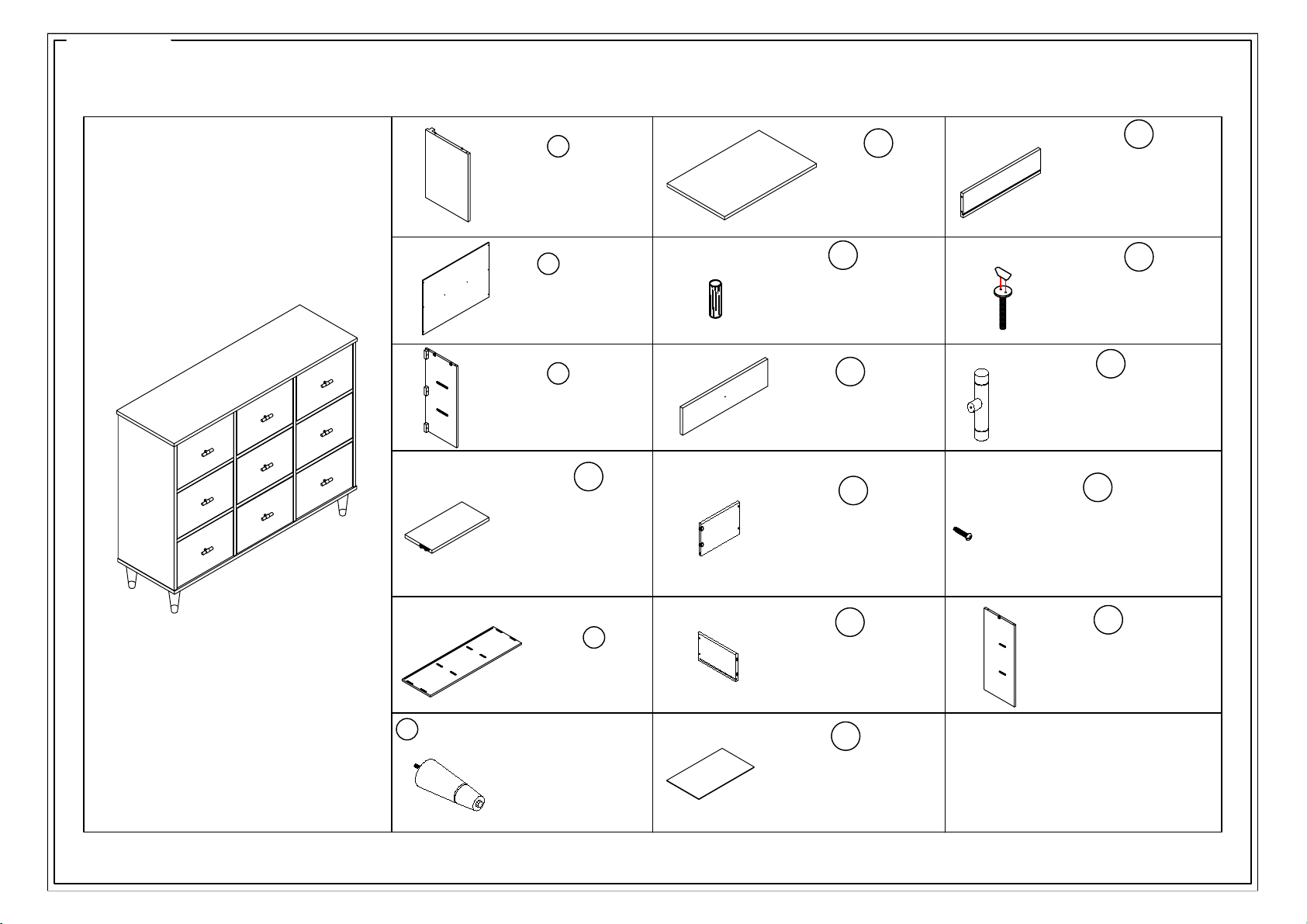
LEFT SIDE PANEL
X1
X1 Panel izquierdo
X1 Panneau gauche
A
X6
Middle shelf
X6
X6
Plato medio
Plaque médiane
D
C
E
X1
X1
X1
Bottom Panel
Piso intermedio
Étage intermédiaire
Leg
X6
X6 Panel izquierdo
X6 Panneau gauche
F
RIGHT SIDE PANEL
X1
X1 Panel lateral derecho
X1 Panneau latéral droit
B
X1
BACK PANEL
X1 Placa posterior
X1 Fond de panier
G
X1
TOP PANEL
X1
X1
Le toit
Techo
H
X8
dowel
Ø8*30mm
X8
Hibiscus Ø8*30mm
X8
Hibisco Ø8*30mm
I
X9
X9 Panel de bombeo
X9 Panneau de pompage
Drawer Front
J
Left Drawer Sides
X9
X9 Placa lateral
X9 Plaque latérale
K
Right Drawer SidesX9
X9 Placa lateral
X9 Plaque latérale
L
X9 Drawer Bottom Panel
X9 Dibujar la placa inferior
X9 Dessiner la plaque inférieure
M
Drawer Back Panel
X9
X9 Despues de bombear
X9 Après pompage
Bolt
Ø1/4"*23mm
X48
Perno
Ø1/4"*23mm
X48
Boulon
Ø1/4"*23mm
X48
N
O
X9
Knob
40*20*L70mm
X9
Manejar
X9
Poignée
40*20*L70mm
40*20*L70mm
P
Handle screw
Ø5/32"*25mm
X9
X9 Tornillo de la manija
X9 Vis de poignée
Ø5/32"*25mm
Ø5/32"*25mm
Page 1 / 8
ASSEMBLY INSTRUCTIONS / NOTICE DE MONTAGE / INSTRUCCIONES DE MONTAJE
Q
Partition PanelX2
X2 Panel lateral derecho
X2 Panneau latéral droit
Page 2
Page 2 / 8
ASSEMBLY INSTRUCTIONS / NOTICE DE MONTAGE / INSTRUCCIONES DE MONTAJE
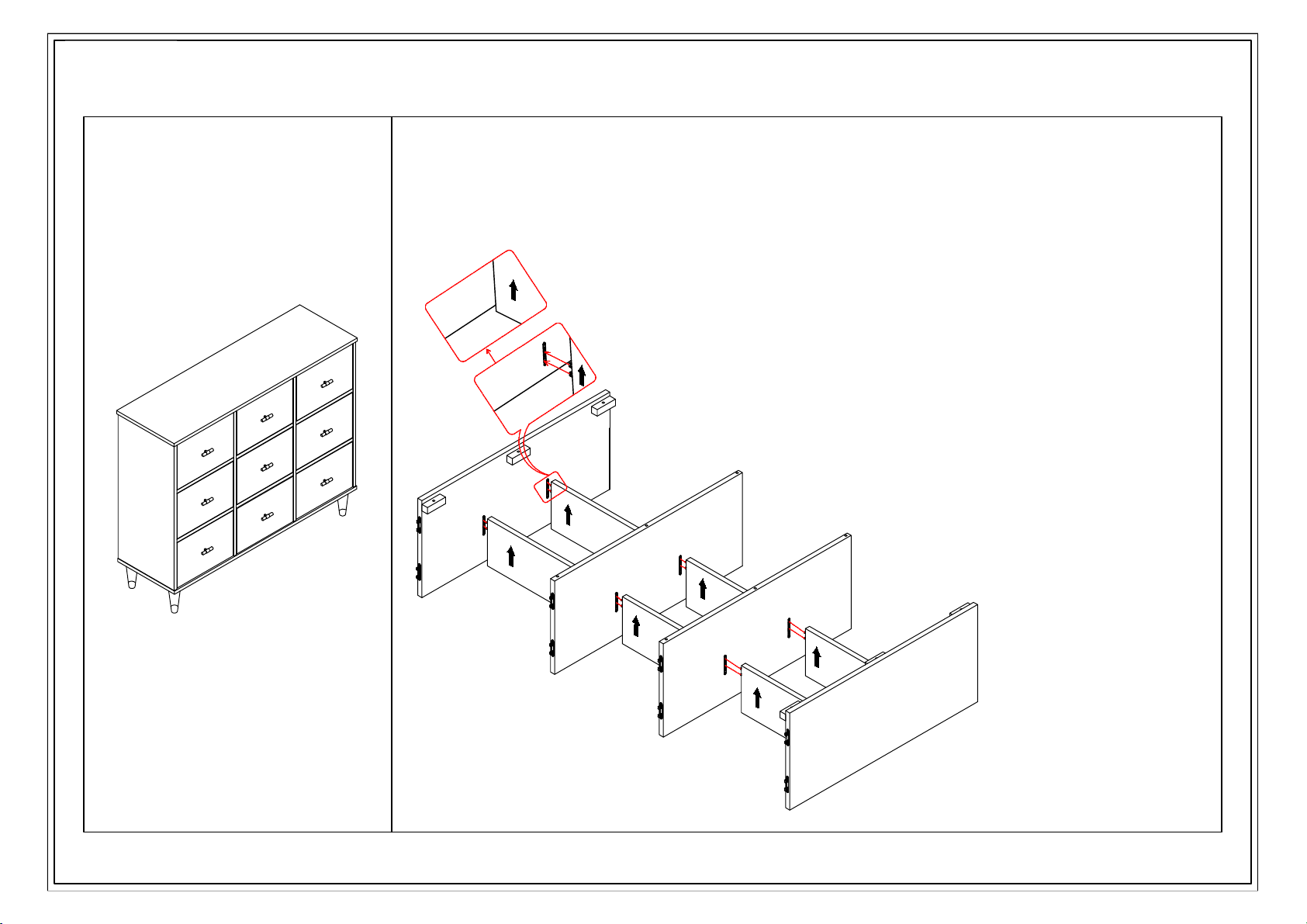
Step 1.
C
A
Q
Q
D
D
D
D
D
D
Step 1.
Insert the hardware on the Shelf (Part D) into the
L/R Side Panels (Parts A&C&Q).For best results, turn
the cabinet on its face and press up on L/R Side Panels
to secure them into place.
Page 3
Page 3 / 8
ASSEMBLY INSTRUCTIONS / NOTICE DE MONTAGE / INSTRUCCIONES DE MONTAJE
E
C
A
Q
Q
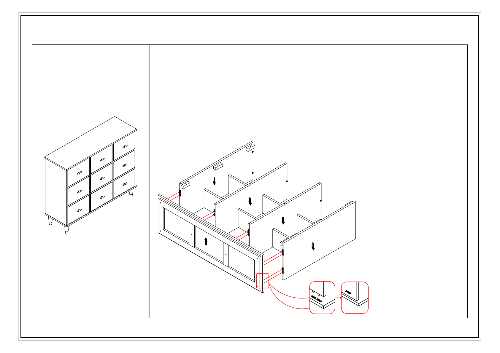
Step 2.
Place the Bottom Panel (Part E) on a soft dry surface with
the hardware and groove facing up. With the grooves and
hardware facing in, insert the Left & Right Side Frames &
Divider (Parts A&C&Q) into the bottom panel and slide forward
to secure in place. For best results turn the cabinet forward
onto its face and press down on the Side Panels (Parts A&C&Q).
Make sure that the grooves are all aligned.
Page 4
Page 4 / 8
ASSEMBLY INSTRUCTIONS / NOTICE DE MONTAGE / INSTRUCCIONES DE MONTAJE
F
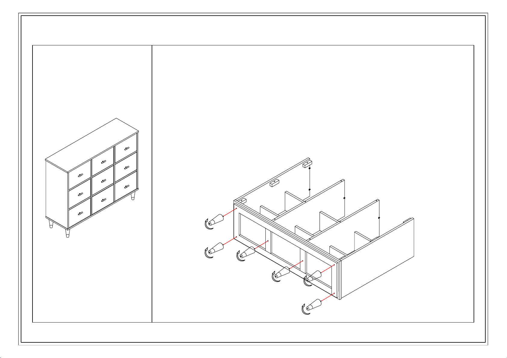
Step 3.
Lay down the total frame on a soft floor,
screw the 6 Legs (Part F) into the bottom of
the frame in the clockwise direction.
Page 5
Page 5 / 8
ASSEMBLY INSTRUCTIONS / NOTICE DE MONTAGE / INSTRUCCIONES DE MONTAJE
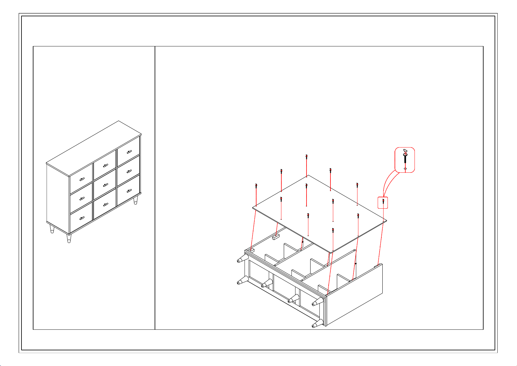
B
A
N
Step 4.
Screw the Bolt (Part N ) into pre-buried
metal holes on the back panel (Part B)in the
clockwise direction.
Page 6
H
Page 6 / 8
ASSEMBLY INSTRUCTIONS / NOTICE DE MONTAGE / INSTRUCCIONES DE MONTAJE
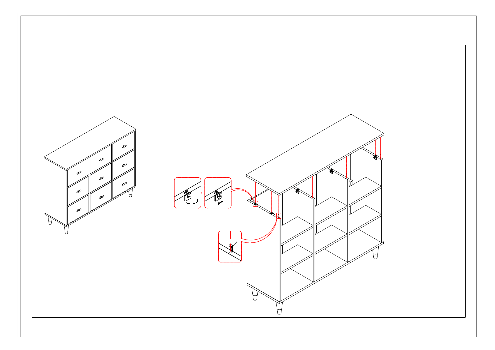
G
Step 5.
Make sure that the switch
locking hardware in Parts A, C & Q
are in the open position as indicated
by the straight arrow in the diagram
below. Align the hardware in the Top
Panel (Part G) with the switch
hardware in the side and back panels
and lower it into place. Making sure
that the hardware is completely
inserted into the top turn the
switches to secure it into place as
indicated by the curved arrow below.
Page 7
Page 7 / 8
ASSEMBLY INSTRUCTIONS / NOTICE DE MONTAGE / INSTRUCCIONES DE MONTAJE
J
K
I
L
M
N
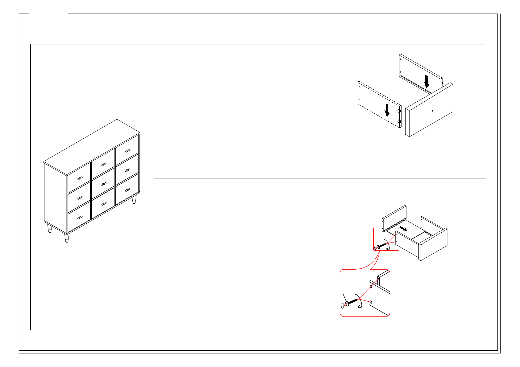
Step 7.
Insert the Drawer Bottom (Part L) into
the grooves in the side panels and press
forward until the front edge goes completely
into the groove in the drawer front. Add the
Back Panel (Part M) making sure the bottom
panel insert completely into the groove.
Insert Bolts (Part N) and turn clockwise to
tighten completely.
Step 6.
Align the hardware on the L/R Drawer
Sides (Part J & K) with the hardware on the
Drawer Front (Part I) making sure that the
grooves on the drawer sides are facing in and
at the bottom of the drawer. Also ensure the the
drawer glides are facing out.
Page 8
Page 8 / 8
ASSEMBLY INSTRUCTIONS / NOTICE DE MONTAGE / INSTRUCCIONES DE MONTAJE
O
P
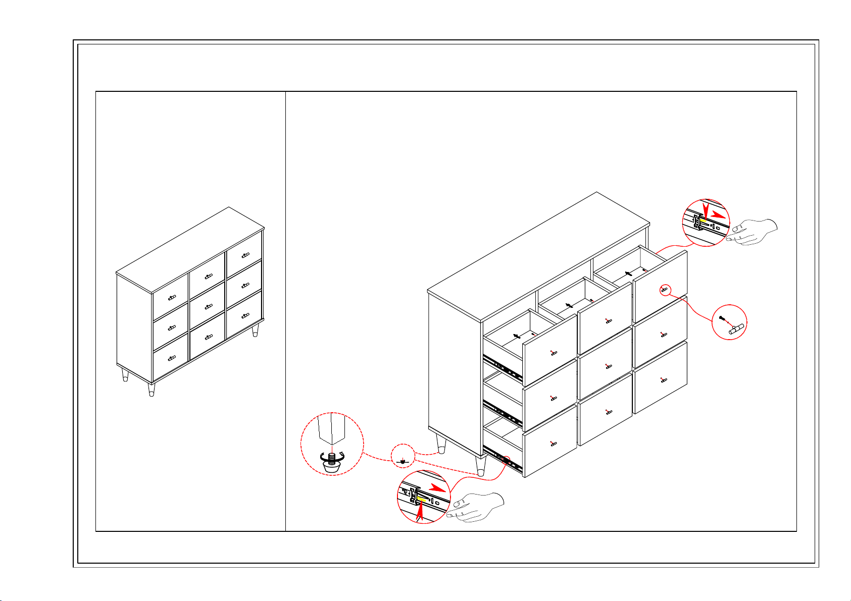
Step 8.
Insert the bolt (Part P) into the hole
from the back side of the drawer
front. Add the Handle (Part O). Use
a Phillips head screwdriver to tighten
the bolt by turning clockwise.
DO NOT TURN THE HANDLE ITSELF
TO TIGHTEN. YOU WILL SCRATCH
THE DRAWER FRONT IF YOU DO.
Align the drawer glides with those in
the cabinet and press forward. Open
and close the drawer to get a smooth glide
Page 9
 Loading...