

Page 1

Series Seven Users Guide
Josephson C700 microphones provide extraordinary flexibility for the user. Any directional
pattern from omni to figure-8 may be derived, and with the C700S, an unlimited number
of “virtual microphones” can be generated by using the side-facing channel produced by
the side-facing figure-8 capsule. This guide is intended to help the user understand the
basic concepts of multiple capsule mid-side stereo and surround techniques, as made
possible by the C700. One approach to explaining this idea is to reduce it to the
mathematics of monopole and dipole transducers (but we’ll save the math for the
appendix, it’s not needed to fully understand and use the microphone as an instrument.)
A major benefit of recording with the C700 is the ability to capture and save the raw
audio components during a session, which can then be used to generate any number of
directional patterns in playback. For a mono track, this allows the directional pattern to be
adjusted during a track as a performer moves around, for instance.
This User’s Guide applies to the both the C700A and the C700S. The only difference
between the microphones is that the C700S has an additional channel for side
information, that allows the direction of the main microphone pattern to be changed. We
are mentioning only a few of the possibilities here; once you have a good understanding
of how the patterns are added together to form new patterns, your own creativity and
experience will take over in suggesting other mixtures of these channels that will produce
other patterns.
The key concept to learn is that the microphone produces a separate output for each of its
capsules. The user mixes these outputs together to derive any desired directional pattern.
In the C700S, there is a third output, and adding this output into the mix allows the
resultant directional pattern to be steered anywhere on the horizontal plane around the
microphone. We have made a control console to derive patterns in the field, but we have
found it much more effective to record the raw signals and matrix them afterward. The
diagram of the control console is included in the Appendix for reference.
The microphone is rated for standard P48 phantom power, please note that all outputs of
the microphone must be connected to phantom power before it will function properly.
Omnidirectional, or pressure microphone (W channel)
Omnidirectional microphones are the simplest. The moving element or diaphragm is
open to sound on one side, and sealed on the other. Sound pressure causes the
diaphragm to move inward, regardless of the direction. For low and mid-frequency sound
waves, the wavelength is much larger than the size of the microphone – so the pressure
wave simply flows around the microphone, pushing in on all surfaces regardless of its
JOSEPHSON ENGINEERING • SERIES SEVEN USERS GUIDE • 2005
Page 2
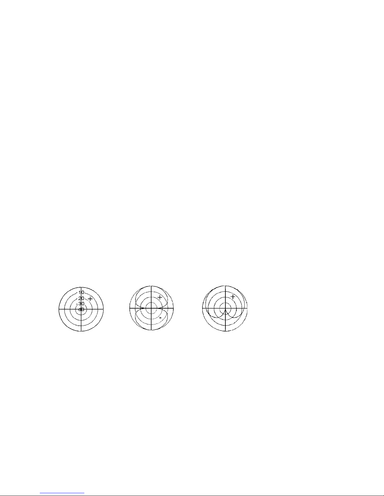
origin. These are called pressure microphones because they mainly respond to sound
pressure. We use a small single diaphragm omni capsule for the W channel; this is the
best way to assure superior off-axis tracking of the response pattern with minimal
response changes.
Figure-8, or gradient microphone (X channel)
Figure-8 microphones have moving elements that are open to sound both front and rear.
Both sides are equally sensitive. Sound pressure coming from the front causes the a
positive electrical output. Sound pressure coming from the rear causes a negative
electrical output. Sound coming from the side pushes equally in both directions, so there
is no output. Figure-8 microphones are sometimes called pressure gradient or velocity
microphones, because their output can be proportional to the gradient or difference
between front and back pressure. We use a large dual-diaphragm capsule for the figure8 signal because its symmetrical construction and high sensitivity produce a uniform frontback pattern with very tight nulls at the sides and a reduced noise floor.
Making a cardioid from an omni and a figure-8
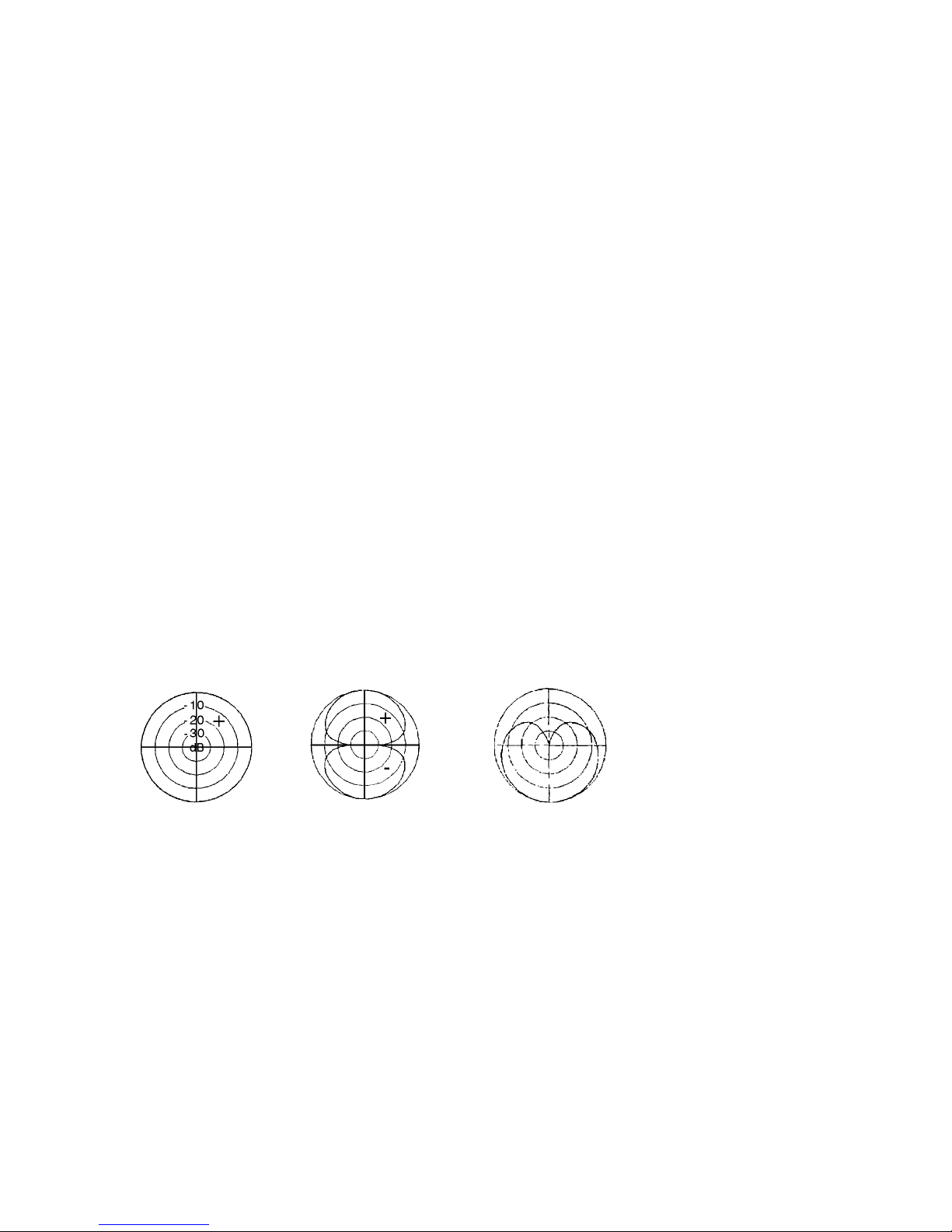
The C700A and C700S include an omni microphone and a forward-facing figure-8
microphone. We call the omni or pressure signal “W” and the front-facing figure-8 “X”.
The microphone outputs are directly driven by the W and X elements. A whole family of
directivity choices is available by mixing W and X. Mixing them at equal levels produces a
cardioid. To understand this, remember that sounds arriving from the rear produce an
output that’s out of phase with the output that would result if they arrived from the front. If
two equal but out-of-phase signals are mixed together, the result is zero. If one signal is a
little bigger than the other, the result of mixing is simply the difference between the two
signals.
+
=
W signal plus X signal equals cardioid
In the cardioid case, for sound coming from the front, the output from W and X are equal.
Add them together, and the sum is double the value of the individual signals because the
omni signal adds to the signal from the front side of the figure-8. For sounds arriving
from the side, the W microphone still picks up with uniform sensitivity but the X
microphone has no output, so the summed output is the same as for the W microphone
alone. For sounds arriving from the rear, the omni and figure-8 signals are again equal
but now out of phase, so the summed signal is zero. Note the + and – symbols, which
are there to remind you that the front side of the figure-8 is in phase with the W signal,
while the rear side is out of phase.
JOSEPHSON ENGINEERING • SERIES SEVEN USERS GUIDE • 2005
Page 3
Other patterns
You can run through all the possible patterns by thinking of the X or figure-8 pattern, and
what happens to the signal if you add some W or omni to it. If the X signal is constant,
and a small amount of W is added, the front lobe of the figure-8 grows a little because
the signals add, and the rear lobe shrinks a little, because the W signal cancels the outof-phase rear lobe of the X signal. When the W signal is increased to a point 10 dB below
the X signal, the pattern has changed to a hypercardioid, with the rear lobe about 10 dB
reduced from the original X signal. Adding W to X also moves the position of the figure-8
null, which is normally at 90º and 270º. Remember, when the W and X signals are equal,
the side nulls are moved all the way back to 180º and merge to form a cardioid pattern.
Whenever the W signal is less than X in the mix, the null will be somewhere between the
sides and the rear. If the W signal is larger than the X signal, there will never be a
complete null, but rather a near-omni pattern that is weighted toward the front, assuming
that W and X signals remain in phase. There are different names for these patterns,
including “wide cardioid” and “subcardioid.” Different variations of “hypercardioid”
patterns may also be called “supercardioid.”
Reverse direction
What happens when you reverse phase of the X signal? All of the same patterns described
so far, but facing toward the rear of the microphone rather than the front. There is of
course some change in high frequency response due to the fact that the W capsule is
facing forward, but for low and middle range frequencies it is truly omnidirectional. This
operation can be described either as the W signal minus the X signal, or as the W signal
plus the minus X signal.
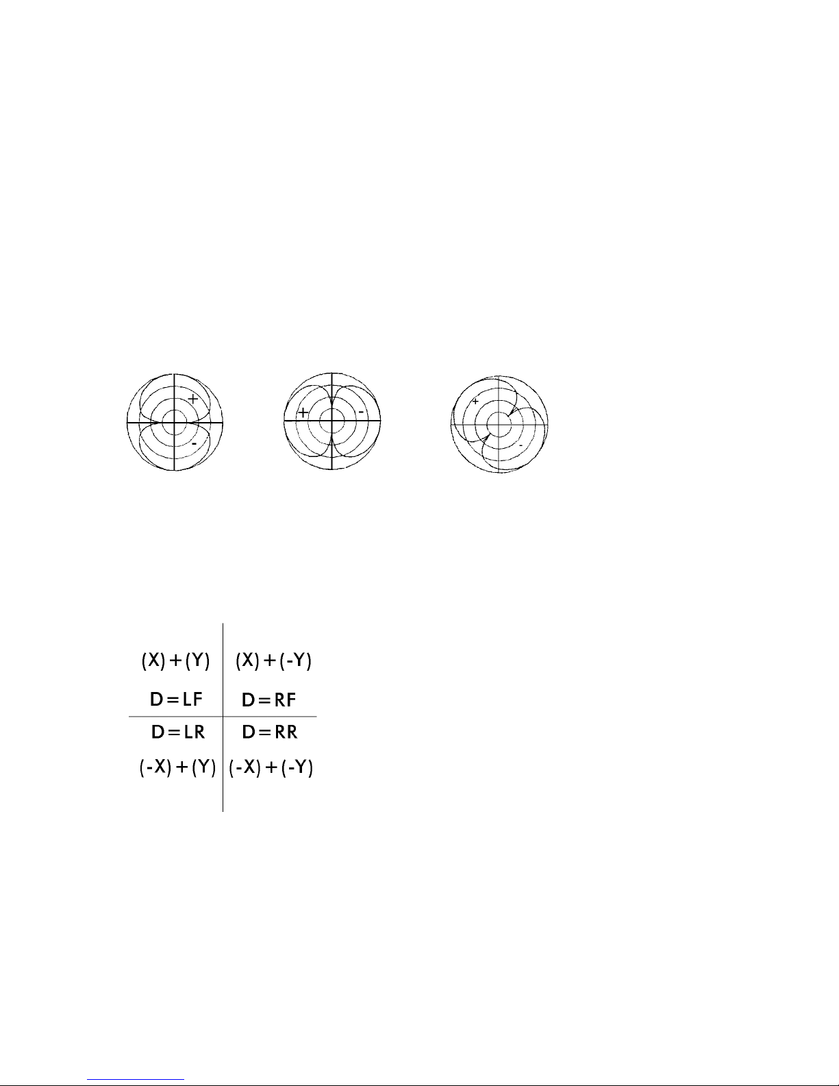
-
=
W signal minus X signal equals reversed cardioid
Summary of Summing
• Control the pattern by selecting the ratio of W to X
Steering (C700S only)
The C700S provides another figure-8 signal from a side-facing microphone capsule
called “Y” to allow the “X” figure-8 signal to be steered in any direction. If you add two
figure-8 microphones together, the result is always still a figure-8 pattern, but pointing in
a different direction. Remember that all the patterns derived with the W and X signals
were facing along a front-back axis. Now consider what would happen if you were to
rotate this axis. The Y signal is facing left, so patterns derived with all Y and varying
JOSEPHSON ENGINEERING • SERIES SEVEN USERS GUIDE • 2005
Page 4
amounts of W added will be about the same as the patterns derived with X and varying
amounts of W – only now they point 90º to the left. If we use a mixture of X and Y, the
resulting pattern will be pointing anywhere from 90º left (all Y) to 45º left (equal
proportions of X and Y) to straight in front (all X). If we continue around and invert the
phase of the Y signal, it’s the same as having the Y capsule pointing right, so we can now
derive all the patterns but pointing anywhere from 0º to 90º right. Continuing around, if
we invert the phase of the X channel, the patterns are facing toward the left rear, and if
we invert the phase of both the X and Y channels, the patterns face toward the right rear.
Summary of Steering
• Virtual direction of X may be changed by adding Y
• Any pattern created with W and X is therefore rotated by adding Y
+ =
X signal plus Y signal equals left-front facing figure-8
To recap, we can rotate the direction of the figure-8 signal by adding Y to X. The resulting
pattern, regardless of the relative amounts of the two signals, will always be figure-8. We
can call the summed X and Y signal “D.” The front lobe of the D signal will be pointing
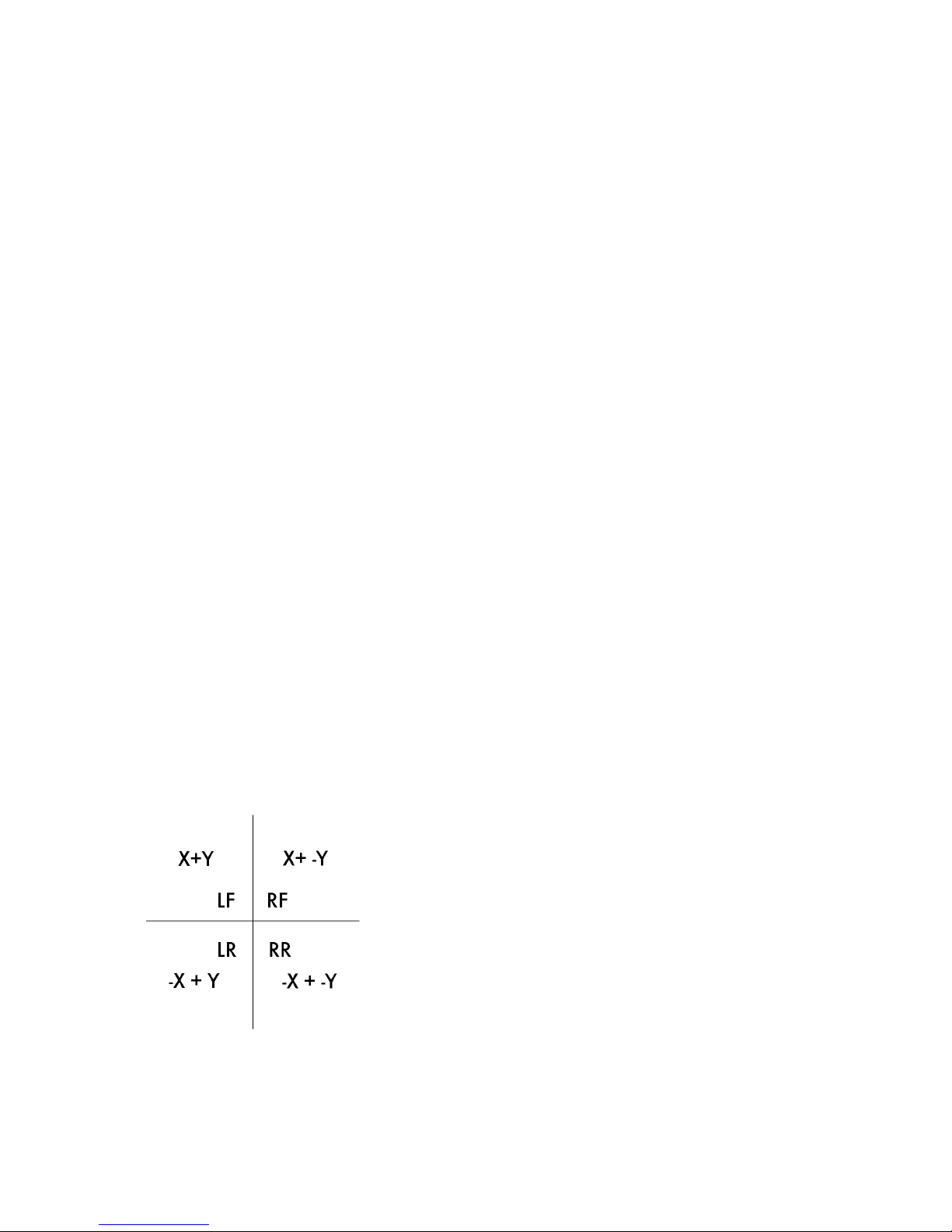
somewhere on a 360 degree circle according to the relative phase of the components:
MS equivalent
If you are familiar with Mid-Side or MS stereo, you will recognize the Y channel as being
the same as the S channel in MS. Any MS technique can be realized with the C700S. Use
the W and X channels summed to produce the forward-facing M signal of the desired
pattern, and the Y channel for the S.
JOSEPHSON ENGINEERING • SERIES SEVEN USERS GUIDE • 2005
Page 5

XY equivalent
The most basic intensity stereo pickup consists of cardioid microphones spaced 45º either
side of the center line. This is often called “XY stereo.” Note, this is a different use of “X”
and “Y” than the names we’ve adopted for the C700 output channels. XY stereo left and
right channels can be created from the M and S signals exactly as described: left is M+S,
right is M-S.
Experiment
Start with the basic X signal and move the sound source around to the side of the
microphone. Notice the sharp null at 90º. Sounds that have assymetrical waveforms will
sound different (as with all figure-8 microphones) when moved to the rear of the mic, due
to phase reversal. This is particularly true if the sound source is the person who’s listening
to the output through headphones, because of mixing the direct in-the-head sound paths
with the headphone path. Begin adding a little W signal, for example at 20 dB below the
X signal. Notice that the sound in front has changed character; the proximity effect is
reduced somewhat. The side-facing nulls have moved back 10-20º and the rear sensitivity
is reduced. Continue adding W to the X signal, and the null will continue to move toward
the back. Adjust the ratio of W and X to be equal, and note that the null is at 180.º
Tracking
We recommend that the raw W and X signals be recorded on a tracking master (and the
Y, if you have a C700S microphone). That way, all the directional pattern and angle
choices can be made in mixdown and your options for pattern selection remain.
For vocals, this can be particularly powerful. After the session, you may decide that using
a more omnidirectional pattern with the singer up close to the microphone is preferable to
working at a greater distance with a more directional pattern. The ratio of direct to
“room” or ambient/reverberant sound can be controlled either way – by working at
different distances or by controlling the pattern of the microphone.
Equalization and Proximity Effect
Another powerful tool available to the C700 user is selective equalization of the omni and
figure-8 capsules. Traditional single-output microphones have a fixed set of characteristics
including directional patterns that vary with frequency and distance. You might decide for
instance that you need a tight hypercardioid pattern above 2 kHz for control of high
frequency ambient sound, but have a vocalist who is moving around a lot causing low
frequency response changes due to proximity effect. The desired pattern might nominally
be a cardioid in the mid-band, but tending to omni at the low frequencies and
hypercardioid at high-mid frequencies. To accomplish this, you would roll off the low
frequencies and boost the mid-high frequencies of the X signal.
JOSEPHSON ENGINEERING • SERIES SEVEN USERS GUIDE • 2005
Page 6

Stereo on a Simple Mixer
The simplest way to use a C700S for stereo with a mixer requires only a wye cord built
with one of its outputs reversed in phase. See the appendix for a wiring diagram. Four
mixer channels will be needed. The W and X channels are connected to the first two mixer
channels, which are panned center. The Y channel is connected to an inverting wye cord;
the straight-through connector is connected to the third mixer channel “Y” which is
panned left, the inverted connector is connected to the fourth mixer channel “-Y” which is
panned right. Start with just the W and X channels, trim the channel gain controls so that
a cardioid (null at 180º) results when the faders are at equal positions. Confirm this by
placing a sound source at the null and adjusting W and X channel gain for a deep drop
in pickup toward the rear. Now move the sound toward the front of the mic and begin to
increase the level of the Y and –Y channels. Adjusting the relative levels of Y and –Y will
shift the image left and right (“pan” or “balance”) and adjusting the ratio of the Y signals
to the W/X signals will adjust the “width” or “focus.”
Using a basic mixing console or digital audio workstation, you can derive all of the
channels needed for stereo, center-channel-stereo, 5.1 or 7.1 surround. In practice, the
mixdown or balance engineer will want to adjust the ratios to produce a convincing sound
image, but these basic relationships for surround are a good starting point:
Left Front = W+X+Y Left Rear = W-X+Y
Center Front = W+X Right Rear = W-X-Y
Right Front =W+X-Y Low Frequency Effects = W (lowpass filtered)
Mixing for Surround
A practical way to derive surround channel mixes from raw C700S W, X and Y signals
uses a mixer or DAW with multiple aux busses. Three busses are sufficient if the channel
strips have the capability of reversing phase from the busses; if they don’t, you’ll need five
busses, one each for W, X, -X, Y and –Y.
If you use digital processing to produce the “inverted” signals, be certain that the DSP
doesn’t introduce unwanted phase anomalies in the signal due to changes in processing
latency. Many digital workstations have variable delay depending on the amount of
processing being done. This would cause shifts in stereo imaging due to differences in
phase between the channels.
JOSEPHSON ENGINEERING • SERIES SEVEN USERS GUIDE • 2005
Page 7
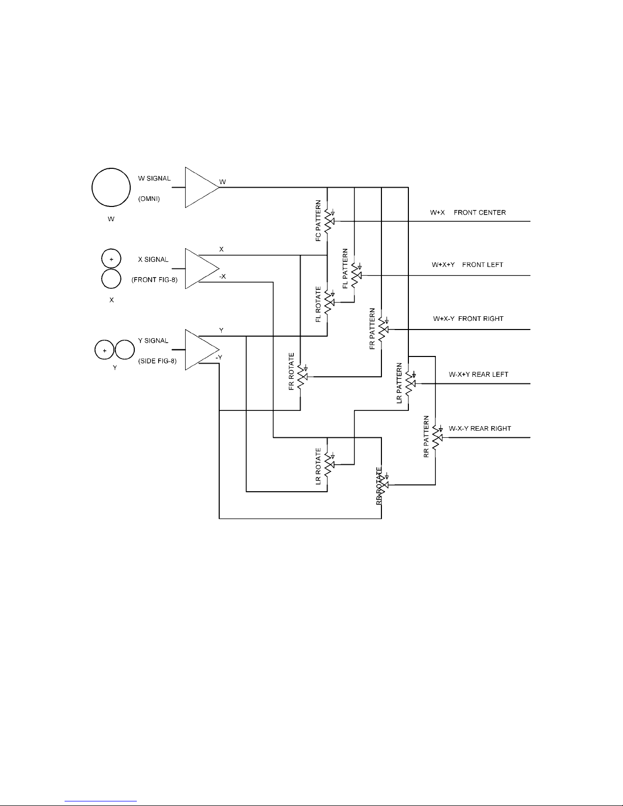
Appendix A - C700S Control Console (not included)
Josephson manufactures an optional microphone preamplifier/control console for use
with the C700S. Five outputs are provided, each with independent pattern and rotation
controls. The block diagram is shown here for reference.
JOSEPHSON ENGINEERING • SERIES SEVEN USERS GUIDE • 2005
Page 8
Appendix B -- For the mathematically inclined
The omni or W microphone signal behaves as a monopole scalar pressure transducer, unaffected
by direction (at low and mid frequencies, where the size of the microphone housing isn’t a
significant fraction of a wavelength). The figure-8 (X and Y) microphone signals behave as dipole
transducers with a response that varies with cosine of the arrival angle. In the C700S, we use a
combination of the two figure-8 signals X and Y to yield a new figure-8 pattern D pointed at a
defined angle θ. We use capital letters to refer to the signals themselves and lower-case to refer to
the proportions of each signal in a mixture.
For these formulas, consider the output as a combination of W and D signals where w+d=1.
Some common ratios are
Omni: all W
Subcardioid/hypocardioid/wide cardioid: 0.66W+0.33D
Cardioid: 0.5W+0.5D
Hypercardioid: 0.33W+0.66D
Supercardioid: 0.25W+0.75D
Figure-8: all D
Steering or rotation of D is achieved by adding X and Y signals. The main axis of the pattern is
located at an angle φ relative to the front of the microphone. φ changes linearly from 0 to 90º by
varying the ratio of X to Y signals in the mix. For a ratio of x and y such that x+y=1, φ=-90y.
φ X Y
90º left 0 1
45º left .5 .5
0 º 1 0
45º right .5 -.5
90º right 0 -1
φ is not restricted to the front quadrants. By reversing the phase of the X signal, it can be pointed to
the rear. φ lies within one of the four quadrants depending on the phase of the X and Y
components. In the C700A there is no Y signal, so φ is fixed at 0 or 180º depending on whether X
or –X is used.
The response r at azimuth angle θ (where θ is the angle from the main axis of D) is found with the
formula r (θ) = w + d cos (θ).
JOSEPHSON ENGINEERING • SERIES SEVEN USERS GUIDE • 2005
Page 9
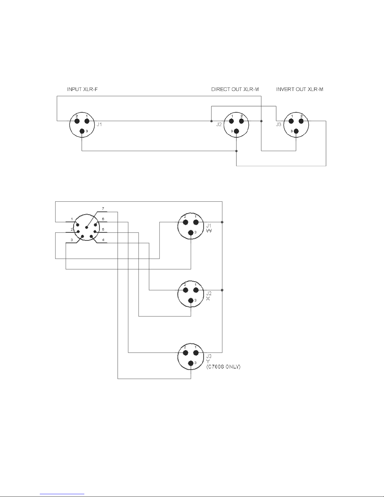
Appendix C1 -- Phase Inverting Wye cord for use with stereo mixers
Appendix C2 – Output Adapter Cable for C700 (furnished with microphone)
JOSEPHSON ENGINEERING • SERIES SEVEN USERS GUIDE • 2005
 Loading...