

Page 1
Instructions for use and
safety regulations
for
Induction heater
JH1500
T 152 1 130915236
Page 2

induction heating
PREFACE
Induction heater JH1500
JH1500 is a mobile induction heater, which
is used for heating metal parts on vehicles
without damaging nearby parts. All other use
of the equipment or use that does not comply
with the instructions in this instruction book,
can cause personal injury and/or damage to
the machine.
If the equipment is used incorrectly, JOSAM
AB cannot be held liable for damage to
the equipment, irrespective of whether the
damage has been caused intentionally or
unintentionally. Nor will JOSAM AB accept
liability for any subsequent nancial losses or
loss of income.
Warranty
JOSAM AB provides a one year warranty
from the machine's delivery date and a
three months warranty on consumable parts
(inductor). The warranty covers material faults
and presupposes normal care and normal
maintenance.
The warranty presupposes that:
• the equipment is installed correctly
and inspected in accordance with the
applicable regulations,
• the equipment has not been modied or
rebuilt without the consent of JOSAM AB,
• only original spare parts from JOSAM AB
have been used in the event of any repairs,
• handling and maintenance has been
performed according to the directions in
this instruction book.
In the event of any complaint, verication is
required that the fault has occurred during the
warranty period and that the equipment has
been used within the capacity limits stated
in the technical data. In the event of any
complaint, the product type and article number
must be stated. These details can be found on
the identication plate, see chapter "Marking".
Information
This instruction book provides advice
and directions for installation, handling,
maintenance and troubleshooting.
IMPORTANT! Read this instruction book
carefully so you can learn the correct way of
using the induction heater. Do not neglect to
do this, since incorrect handling can lead to
personal injury and damage to the equipment.
The illustrations in the instruction book are
only to help with comprehension and do not
necessarily represent the equipment's exact
appearance. The equipment is intended to
be used in accordance with current practice
and the applicable safety regulations. The
equipment, as shown in the instruction
book, may be changed in the future without
warning.
The content of this instruction book can also
be changed without warning.
This instruction book contains information
that is protected by the Copyright Act. No
part of this publication may be reproduced
or published without the written consent of
JOSAM AB.
Conformance with directives and
standards
The JH1500 series is designed and
manufactured by JOSAM AB, an
EN‑ISO9001/14001 certied development
and manufacturing company. The JH1500
series conforms with the requirements in the
CE standard.
2
Page 3

induction heating
CE CERTIFICATE
Induction heater JH1500
3
Page 4

induction heating
TABLE OF CONTENTS
Induction heater JH1500
Preface 2
Warranty .........................2
Information ........................2
Conformance with directives
and standards .....................2
CE certicate 3
Table of contents 4
Introduction 5
General Information .................5
Marking .......................6
Safety 7
General information .................7
General warnings ..................8
Safety sign .......................10
The placing of the safety sign ........11
Safety devices ....................11
Installation 12
Packaging check and delivery ........12
Filling the water tank ...............13
Connection to the electric supply ......14
Description 15
Cooler section ....................16
Electrical section ..................17
Main power switch ..............18
Residual current breaker .........18
Main fuse .....................18
Cooler fuse ...................18
USB connection ................18
Control panel .....................19
Alarm indicators ................20
Operation indicator .............20
Hose packet ......................21
Connection block ...............21
Handheld transformer with hose kit . 21
Trigger button ..................21
Inductor ......................22
Usage 23
General information about induction ...23
Information about heating ...........23
Heating .........................24
After completed work ...............25
Maintenance instructions 26
Maintenance interval ...............26
Maintenance description ............26
Check the cooling water .........26
Check the residual current breaker . 26
Check the hose couplings ........27
Check and clean the condenser ...27
Check cable glands on the
connection block ...............27
Fitting the inductor ..............27
Troubleshooting 28
Troubleshooting table ...............29
General information 31
Manufacturer .....................31
Machine designation ...............31
Intended usage areas
and environments .................31
Warranty ........................31
Recycling ........................31
Service .........................31
Technical data 32
4
Page 5

induction heating
INTRODUCTION
General information
JH1500 is a mobile induction heater, which is
used for heating up metal parts on vehicles
without damaging nearby parts. The induction
heater produces heat without physical contact
and without naked ames. Using the induction
heater makes it possible to leave nearby,
sensitive parts in place.
The are many application areas for the JH1500.
For example, the induction heater can be used
for:
• Heating nuts and bolts that have rusted in
place
• Heating hinge pins that have rusted in place
• Heat‑shrinking steel and aluminium panels
when making repairs
• Heating, for example, couplings to exhaust
systems that have rusted in place and
places that are difficult to reach
• Heating screws that have rusted in place
• Nuts on the suspension or the steering
• Simple removal of underbody protection and
PVC coating
• Frame straightening
Induction heater JH1500
The JH1500 is designed to heat metals, by
concentrating a powerful magnetic eld at the
inductor head. The induction heater also works
well on aluminium. The magnetic eld alternates
at a frequency of ca 14‑30kHz. The magnetic
eld induces eddy currents in the material, and
the electrical resistance produces heat in the
metal.
Since heat is created due to electrical losses
and radiation from the plates, JH1500 has an
internal cooling system, using water as the
coolant. The water circuit cools the high‑power
electronics, cables, induction handle and
inductor. When the machine starts, the water
pump begins to pump the cooling water in the
induction heater.
5
Page 6

induction heating
Marking
The identication plate is located on the back
of the JH1500.
Induction heater JH1500
#####
#####
400 V 200 V
6
Page 7

induction heating
SAFETY
General information
The JH1500 is designed and tested to conform
to the strictest safety requirements. Read the
following instructions carefully before you start
using the JH1500 and pay attention to the
applicable operating instructions, in order to
operate the induction heater safely.
The information provided in this manual
describes the work routines that we consider
work best, but may under no circumstances
be used as an excuse to ignore one's
own personal responsibility or applicable
regulations.
Great care has been taken during the design
and manufacture of the JH1500 to ensure
the system conforms with the applicable
safety regulations for this type of equipment.
During use and other work, everyone has a
personal responsibility for their own and other
individuals' safety.
Induction heater JH1500
Safe use of the induction heater is
guaranteed by using the equipment correctly,
in accordance with the descriptions and
instructions in this manual. By reading and
following the safety regulations, the JH1500
user can ensure a safe work environment for
himself/herself and his/her colleagues.
7
Page 8
induction heating
GENERAL WARNINGS
The following types of warnings and
information are used in this manual:
Induction heater JH1500
WARNING!
Warning is used in this manual
to draw attention to possible
dangers that can result in
personal injury. When an
instruction is given, it is normally
followed by a short explanation
and the possible results if the
instruction is not followed.
IMPORTANT!
Important is used to draw
attention to possible dangers
that can result in damage
to the equipment and/or the
environment.
NOTE!
Note is used to indicate
additional information that
should be followed to obtain
problem free or the best use of
the equipment.
WARNING!
Do not ll the water tank with
anything other than decalcied
water mixed with propylene
glycol. Incorrect handling can
cause personal injury and/or
damage to equipment.
WARNING! Do not touch
objects that have been close to
the inductor without checking
that they have cooled down.
WARNING! Do not touch the
inductor while it is activated
and the strong magnetic eld
and the heat are on. Danger of
personal injury.
WARNING! The work area
must be kept free of ammable
material when you are working
with the induction heater.
Apart from the safety signs shown in
the section "Safety Signs", the following
WARNING! Make sure that re
ghting equipment is available.
Danger of personal injury.
warnings and important information can
be found in the operating instructions:
WARNING! Loose cables
WARNING! Do not place the
induction heater on unlevel or
instable surfaces. The induction
heater can fall over and cause
personal injury or serious
damage to the induction heater.
WARNING! All electrical modi‑
cations must be performed by
a qualied electrician.
Danger of electrical shocks.
8
and hoses constitute a risk for
tripping. Danger of personal
injury.
WARNING! If you do not remove
paint and other chemicals from
the material before you heat it
up, you must use an extraction
fan to remove vapours that are
injurious to health. Danger of
personal injury.
Page 9

induction heating
GENERAL WARNINGS
Induction heater JH1500
WARNING! When you are
using the JH1500, performing
maintenance on it or working
near it, do not wear or use metal
objects such as watches, rings,
keys, etc. The objects can be
heated up by the magnetic eld
from the JH1500 and cause
burn injuries.
WARNING! Most of the
servicing must be performed
by service personnel or service
support from JOSAM AB.
Danger of electrical shocks.
WARNING! Never remove any
of the protective covers and
never perform any work on the
induction heater without rst
pulling the plug out of the wall
socket. Wait one minute. Danger
of electrical shocks.
WARNING! It is the owner's
responsibility to ensure that the
equipment has been installed in
accordance with the instructions
in this manual. It is also the
owner's responsibility to ensure
that the equipment is inspected
according to the applicable
regulations before it is used.
IMPORTANT! For
environmental reasons, it is
important that the equipment
is disassembled in an
environmentally friendly way.
IMPORTANT! Risk of con‑
densation in the JH1500. Fill the
water tank with room tempered,
not cold, water. If you move the
JH1500 from a cold location,
you should wait until the
water has warmed up to room
temperature before use.
WARNING! Remove the
induction heater's plug from the
wall socket before you begin
any form of service, cleaning
or maintenance. Danger of
electrical shocks.
WARNING! The inductor can
become very hot. Danger of
burn injuries.
WARNING! Read this manual
carefully so you can learn how
the equipment is to be used in
the right way. Do not neglect to
do this, since incorrect handling
can lead to personal injury and
damage to the equipment.
IMPORTANT!
During transport the water
tank must always be sealed.
Otherwise, there is a risk of
water leaks.
9
Page 10

induction heating
Safety sign
The safety sign must always be present and in
good condition, attached to the stated place.
If the sign is damaged or is missing, the owner
bears the responsibility for replacing it without
delay.
You can nd the following safety symbols on
the induction heater:
WARNING
Wear suitable safety equipment (protective
gloves and safety goggles) when you use the
equipment.
Induction heater JH1500
WARNING
Sparks from the induction heater can cause
res.
WARNING
Danger of tripping over loose hoses etc.
WARNING
Always read the user instructions before using
the product.
WARNING
Residual voltage. Wait one minute after
disconnecting before opening enclosure.
WARNING
When the JH1500 induction heater is activated,
there is a magnetic eld from the induction
head in its immediate vicinity.
10
WARNING
The JH1500 induction heater can interfere
with pulse generators. It is possible that a
pacemaker will not function correctly in the
vicinity.
Page 11

induction heating
The placing of the safety sign
The safety sign is placed on the back of the
JH1500, as in the picture.
Induction heater JH1500
Safety devices
When the induction heater is in use, the
inductor, cables, electronics and transformer
can frequently become very hot. To protect
the induction heater from overheating, it is
cooled continuously when in operation. The
induction heater is cooled all the time by
water that circulates through the inductor. The
water begins to circulate when the machine is
started. A sensor detects the water ow and
trips the induction heater if the ow is blocked.
The JH1500 must be connected to earth.
It has an inbuilt residual current breaker to
protect the user in case of a ground fault. It
also has an automatic fuse, which trips if the
current exceeds 32 A (for JH1500‑400V) or
63A(forJH1500‑200V).
In case the JH15000 would get overheated,
the overheating protection automatically
disables the heating function to protect the
machine and its electronic parts. However, the
cooling system continues to cool the machine
to make it ready for operation again.
The inductor handle is insulated to protect the
user from electric shocks.
11
Page 12

induction heating
INSTALLATION
The JH1500 is inspected and tested before it
leaves the factory to warrant uniform quality
and the greatest possible reliability. Below
follows a description of the installation and
general tips and instructions.
Induction heater JH1500
WARNING! Do not place the
induction heater on uneven or
unstable surfaces. The induction
heater can fall over and cause
personal injury or serious damage
to the induction heater.
WARNING! It is the owner's
responsibility to ensure that the
equipment has been installed in
accordance with the instructions
in this instruction book. It is
also the owner's responsibility
to ensure that the equipment is
inspected according to applicable
regulations before it is used.
Packaging check and delivery
Check the delivery against the packing
list, consignment note or other delivery
documentation to ensure that everything is
included in the correct quantities. Check the
JH1500 carefully, to assure yourself that no
damage has been incurred during transport.
If any part has been damaged or is missing,
the induction heater must not be used before
the part has been repaired or replaced. If
there is anything missing, contact the supplier.
Remove all of the packaging material from the
induction heater.
12
Page 13

induction heating
INSTALLATION
Filling the water tank
The JH1500 is delivered with a lled water
tank, but if the tank needs to be lled manually
at some point, follow the instructions below.
Fill the water tank with a mixture of decalcied
water and 30 % propylene glycol.
1. Open the front cover.
2. Open the tank cap.
3. Fill the water tank (it should be lled to
between 80‑90%).
Induction heater JH1500
WARNING! Do not ll the
water tank with anything other
than decalcied water mixed
with propylene glycol. Incorrect
handling can cause personal
harm and/or damage to
equipment.
IMPORTANT! Risk of
condensation in the JH1500.
Fill the water tank with room
tempered, not cold, water. If you
move the JH1500 from a cold
location, you should wait until
the water has warmed up to
room temperature before use.
NOTE! Do not ll the tank
completely, since the water
expands as it heats up. Fill the
tank with 35 litres of uid.
13
Page 14
induction heating
INSTALLATION
Connection to the electric supply
The induction heater is available in two
versions: 200 V or 400 V, 50–60Hz. The 400V
version is equipped with a plug so it can be
plugged into a wall socket. The source of
electrical current must be earthed and it must
also be protected by a fuse, according to the
following:
• The electric supply must be protected by
a 32A(400V) or 63A(200V) fuse when
using maximum power (step 5).
The JH1500 is connected to the electric mains
as follows:
Induction heater JH1500
• Plug the JH1500 into a wall socket.
NOTE! The JH1500‑200 V is
delivered without a plug.
A plug suited for local electrical
conditions must be acquired
separately and mounted by a
qualied electrician.
14
Page 15

3
induction heating
DESCRIPTION
The machine comprises:
1. cooler section
2
1
2. electrical section
3. hose packet with inductor
During heating, a powerful magnetic eld is
concentrated in the inductor. The magnetic eld
alternates direction and induces eddy currents
in the material, which gives rise to heat. Since
intense heat is created in the work piece and
inductor, cooling water is used for cooling the
machine and its electronic parts. The control of
the cooling system is totally automatic.
The connection cable provides the machine's
electrical section with current, which in turn
power supplies the hose packet, inductor and
cooler section. The cooling section controls the
temperature of the components by circulating
cooling water in the hose packet, inductor and
a cooling block in the electrical section.
Induction heater JH1500
15
Page 16

induction heating
DESCRIPTION
1
Induction heater JH1500
5
5
4
3
2
Cooler section
The cooler section consists of a:
1. cooling water tank
2. water pump
3. connection box
4. condenser
5. condenser fan
16
Page 17
induction heating
DESCRIPTION
Induction heater JH1500
1
345
2
6
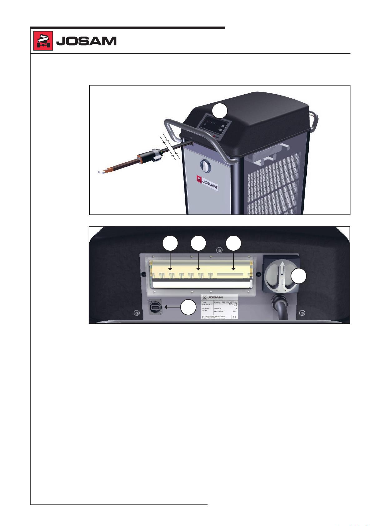
Electrical section
The electrical section has three main functions,
namely supplying current to: the hose packet,
electronic components and the cooling section.
The electrical section comprises:
1. control panel
2. main power switch
3. residual current breaker
4. main fuse (32 A/400 V or 63 A/200 V)
5. cooler fuse (10 A/400 V or 16 A/200 V)
6. USB connection
17
Page 18

induction heating
DESCRIPTION
Main power switch
When the main power switch is turned on, the
machine is connected to the electrical supply.
Residual current breaker
The machine is equipped with a residual
current breaker, which trips in the event of
an earth fault. There is a test button on the
residual current breaker. When the test button
is pressed, the residual current breaker should
trip.
Induction heater JH1500
Main fuse (32 A/400 V or 63 A/200 V)
The main fuse trips in the event of a fault in the
current supply to the hose packet.
Cooler fuse (10 A/400 V or 16 A/200 V)
The cooler fuse trips in the event of a fault in
the current supply to the water pump, fan or
compressor.
USB connection
For service work and updates.
18
Page 19

induction heating
DESCRIPTION
Control panel
Operation indicatorAlarm indicators
Induction heater JH1500
Increase power
On/Off
Reduce power
Power indicator
The following functions can be found on the
control panel.
On/Off
To use the induction heater, after it has been
connected to the electric mains, you must press
the On/Off button. When you have pressed the
button, one or more of the yellow LEDs lights up
on the power indicator.
Increase power
Increase power by one step (step 1‑5).
Reduce power
Decrease power by one step (step 1‑5).
Power indicator
Shows the chosen power (1‑5) and that the
unit is on.
Power 5
Power 4
Power 3
Power 2
Power 1
19
Page 20

induction heating
DESCRIPTION
Alarm indicators
The alarm indicators notify the user if a fault
occurs with the induction heater.
The alarm indicators are marked by a red LED.
Overheating
The red LED for overheating lights, if the
electronics become overheated. The induction
heater does not function if this indicator is
lit. The light goes out, when the temperature
drops below the warning limit.
Water ow
The red LED for the water ow lights, if the
cooling water is not owing as it should, that is,
if the water pressure is too low. The induction
heater does not function when this indicator is
lit.
Induction heater JH1500
General electronic alarm
If both LEDs are blinking at the same time,
the cause is often that one of the phases is
missing in the wall outlet. This alarm indication
will also be shown if the machine is consuming
current even though it is in idle, or if a current
sensor is faulty.
Operation indicator / Trigger activated
The operation indicator provides the user with
information when the induction heater is in use.
The green LED begins to blink when the
trigger is pressed in. It indicates that the cable
to the handheld transformer isn't damaged,
that the water ow is functioning and that
correct power is reached in the inductor head.
20
Page 21
induction heating
DESCRIPTION
Induction heater JH1500
1
2
3
4
2
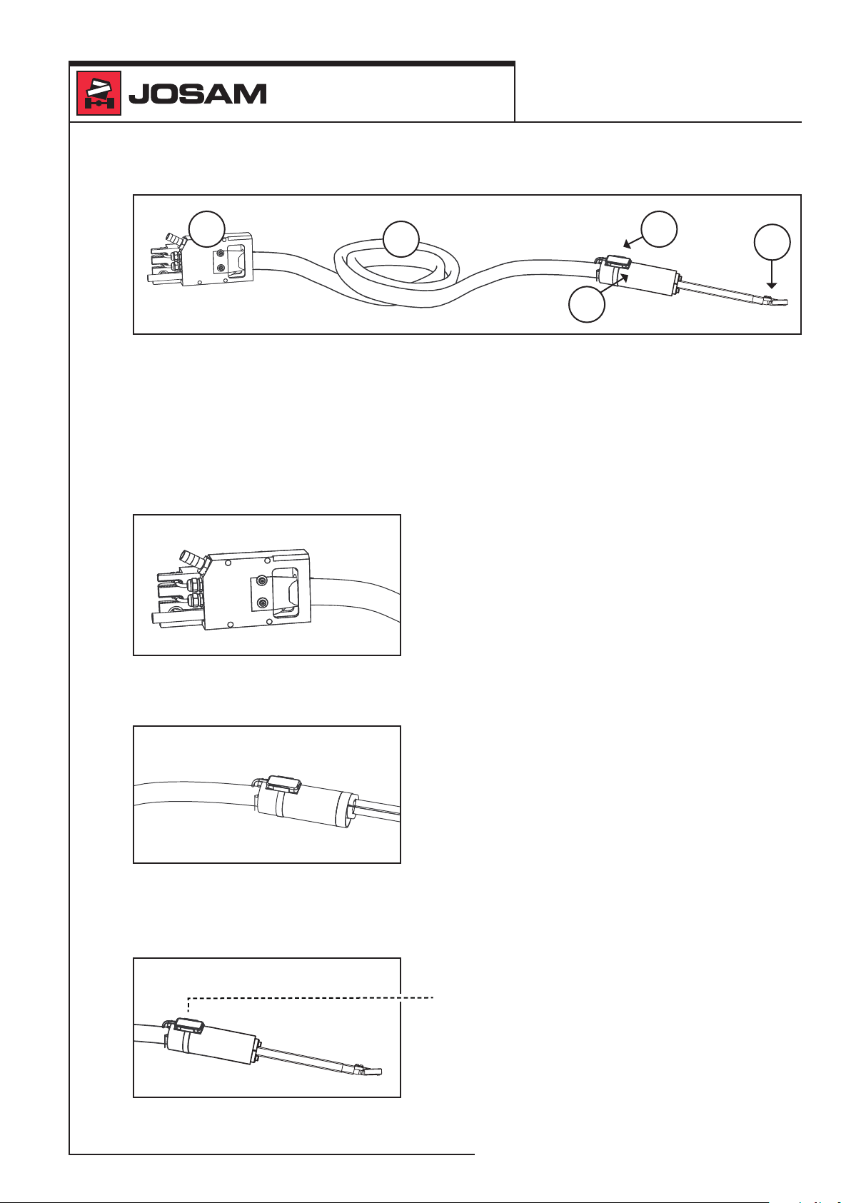
Hose packet
The hose packet consists of:
1. connection block
2. handheld transformer with hose kit
3. operating button
4. inductor
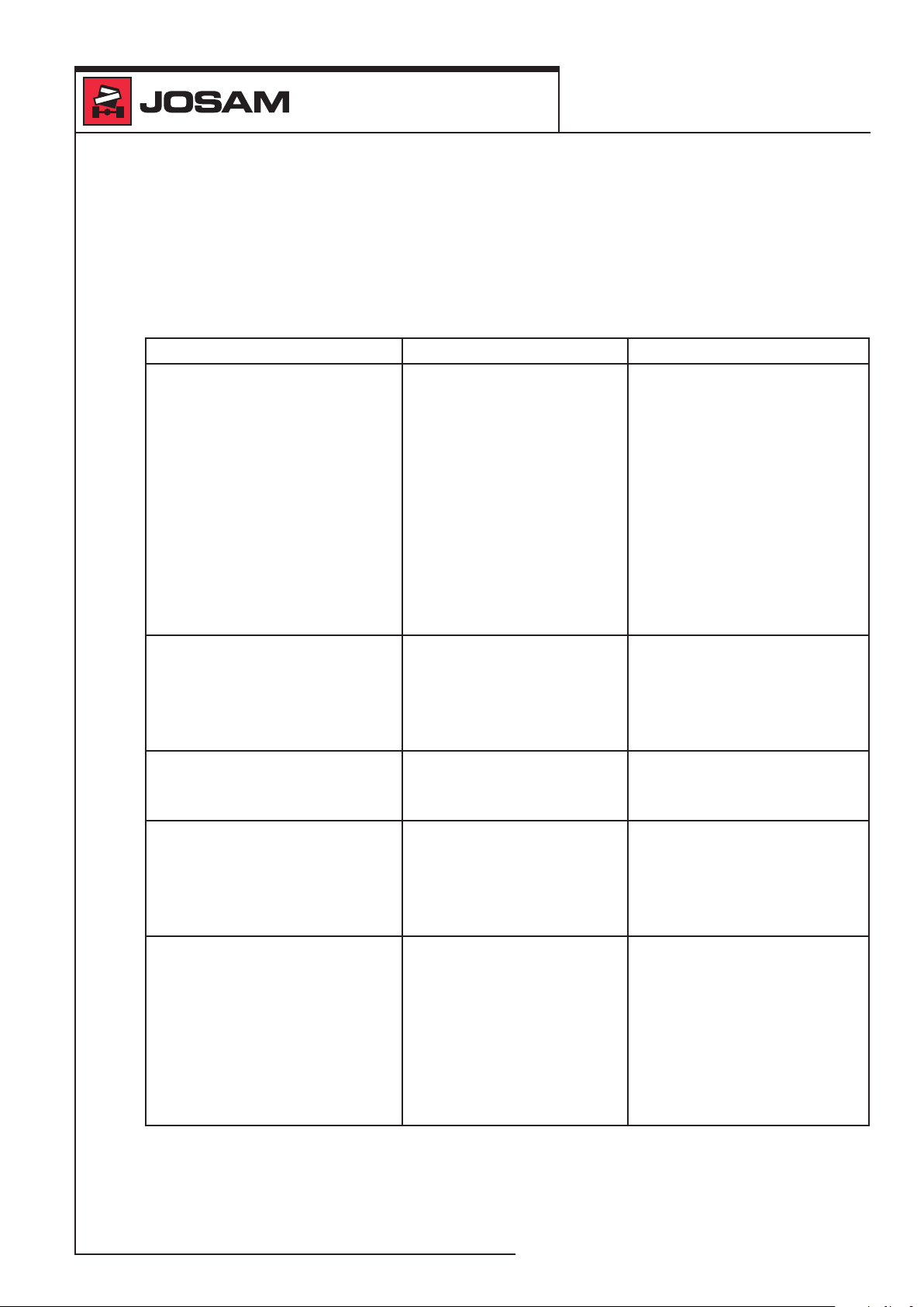
Connection block
The connection block is mounted below the
electrical section, its upper section protrudes
into the electrical section. The cooling water's
pressure and return ow runs through the
connection block. The power cabling runs
from the electrical section, via two unions in
the connection block, and further, through the
hose up to the handheld transformer.
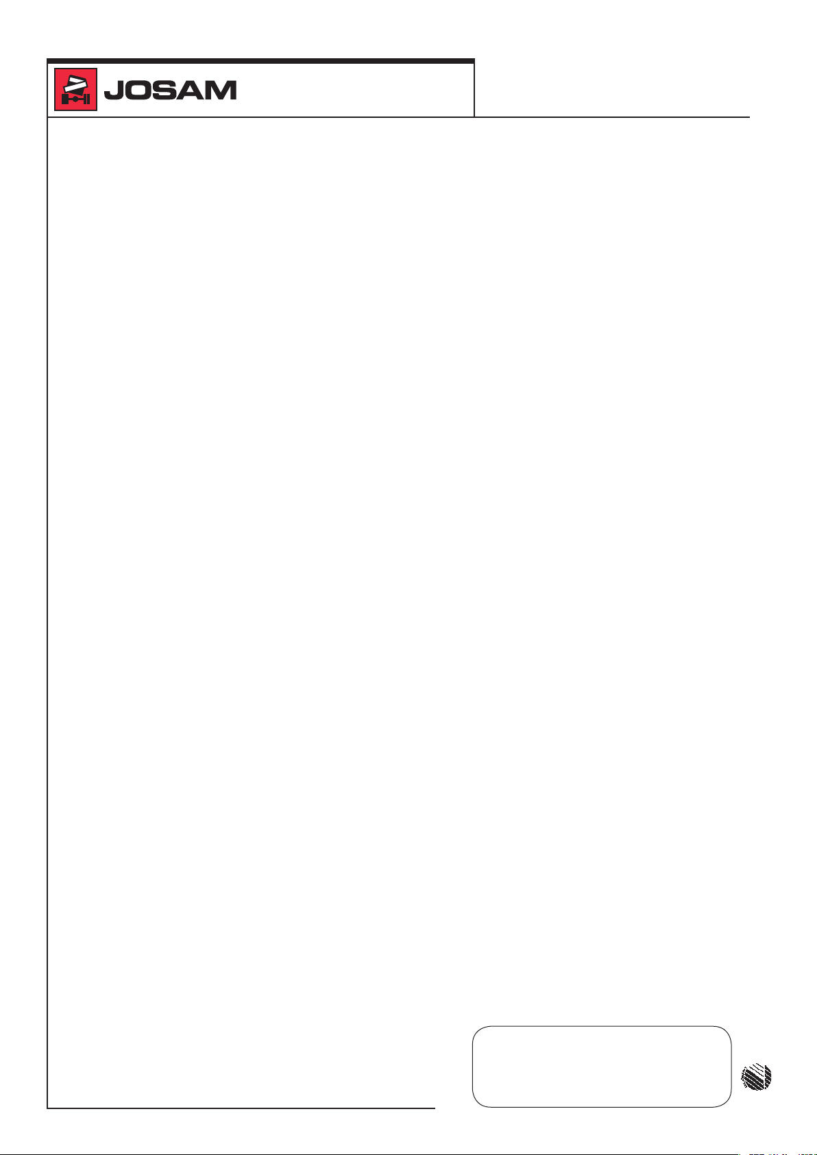
Handheld transformer with hose kit
During use, the handheld transformer functions
as a tool handle, the control button is mounted
permanently to the handheld transformer.
The inductor is attached to the handheld
transformer by four screws.
The hose kit comprises two hoses for the
cooling water's pressure and return ow. In
the hose for the pressure ow, there is also a
cable. Two earth cables and a control cable run
on the outside of the hoses.
Trigger button
Current switch to activate the heating. It sits in
a holder on the handheld transformer.
21
Page 22

induction heating
DESCRIPTION
Inductor
During use, the inductor is supplied with a
voltage and an alternating magnetic eld is
generated by the eld power amplier at the
inductor's tip. The cooling water circulates
through the inductor.
Induction heater JH1500
22
Page 23

induction heating
COLOUR TEMPERATURE SCALE
White
Light yellow
Yellow
Dark yellow
Induction heater JH1500
USAGE
General information about induction
Induction heaters work with low voltages and
high currents in order to create a magnetic
eld. The magnetic eld is concentrated to
the eld amplier. When the tip is placed
against iron or another magnetic material, the
magnetic eld is short‑circuited and heat is
formed.
Information about heating
It is important to control the temperature
of the heated work piece, if quality is to be
maintained.
The human eye is inuenced by the ambient
conditions. The illumination changes how the
eye experiences colour. Therefore, the heated
work piece should be examined in daylight.
The colour temperature scale, to the left,
simplies visual control and, at the same time,
the stepwise presentation of temperature
improves the accuracy during heating.
Orange
Light red
Light
cherry red
Cherry red
Dark
cherry red
Dark red
Brownish-red
23
Page 24

induction heating
USAGE
Heating
Induction heater JH1500
Warning! The user must
remove metal objects such as
watches, rings and suchlike
before use. Danger of serious
personal injury.
Warning! Take care that there is
good ventilation so as to avoid
breathing in the gases that are
formed during heating.
Warning! The work area must
be free from ammable objects.
Risk of re.
1. Place the inductor's tip at against the
object.
2. Press and hold the operating button.
Warning! Do not touch any
object that has been close to
the coil without checking the
temperature rst. Danger of
serious personal injury.
Important! Never keep the
inductor still for a longer time.
Risk for serious damage to
property.
24
3. Move the inductor's tip around the area to
be heated.
Page 25

induction heating
USAGE
4. Release the operating button.
5. Lift the inductor out of the way.
After completed work
1. Turn off at the main power switch.
2. Wrap the hose packet around the big
handle on the machine and place the
inductor in the holder.
3. Wrap the power cable around the small
handle on the machine.
Induction heater JH1500
Note! Never press the inductor
against the object, since this
would shorten the inductor's
service life more quickly than
necessary.
25
Page 26

induction heating
MAINTENANCE INSTRUCTIONS
Maintenance interval
Once a month:
• Check the cooling water
• Check the residual current breaker
• Check the hose couplings
• Check connection surface between heating
tip and handheld transformer
Once a year or when needed:
• Check and clean the condenser
• Check the cable connections
Maintenance description
Check the cooling water
Induction heater JH1500
Note! Do not mix different types
of glycol in the cooling water.
This would make the freezing
point impossible to control.
Check that the cooling water tank is lled to at
least 80% with cooling water. Note, for more
powerful heating (>15 min/occasion), the
cooling water level should be higher (80‑90%).
To rell the cooling water use decalcied
water and propylene glycol.
Check the residual current breaker
Check the residual current breaker once a
month, by pressing the test button (T). After the
test button is pressed in, the residual current
breaker must trigger. If this does not happen,
the residual current breaker must be replaced
before the machine is used again.
26
Page 27

induction heating
MAINTENANCE INSTRUCTIONS
Check the hose couplings
Check that the hose couplings in the induction
heater do not leak. Replace hoses when
necessary. To be checked once a month.
Induction heater JH1500
Note! If the machine is used
with a lot of cold water, a large
quantity of condensate is
formed, which can accumulate
in the hose packet and/or
the machine. This may be
misinterpreted as an indication
of leaking hoses.
Check and clean the condenser
Note! The condenser must
absolutely not be cleaned with a
high‑pressure wash.
The outside of the condenser should be
cleaned at least once a year, ahead of the
warm season, more often as required, so as
to obtain the best cooling effect. Rinse with
degreasing uid and tepid water.
Also check that the condenser fan is working
and that there is no unusual noise.
Check cable glands on the connection block
Check the cable glands on the connection
block, to ensure they are sealed. Tighten the
cable glands, if necessary. To be checked once
a year.
Fitting the inductor
Before use, the inductor must be attached
to the handheld transformer. The inductor
is screwed in place with four stainless steel
screws + washers.
27
Page 28

induction heating
TROUBLESHOOTING INSTRUCTIONS
The troubleshooting instructions in this
chapter will help you to quickly locate and
correct the majority of faults that can arise
when you use the JH1500.
WARNING! All electrical modi‑
cations must be performed
by a qualied electrician.
Danger of electrical shocks.
WARNING! Remove the
induction heater's plug from the
wall socket before you begin
any form of service, cleaning
or maintenance. Danger of
electrical shocks.
Induction heater JH1500
WARNING! Never remove
any protective covers and
never perform any work on the
induction heater without rst
removing the contact from the
wall socket. Wait one minute.
Danger of electrical shocks.
WARNING! When you are
using the JH1500, performing
maintenance on it or working
near it, do not wear or use metal
objects such as watches, rings,
keys, etc. The objects can be
heated up by the magnetic eld
from the JH1500 and cause
burn injuries.
28
Page 29
induction heating
TROUBLESHOOTING INSTRUCTIONS
The following troubleshooting table is to help you locate faults on the induction heater.
However, the table only shows the most common faults and their possible causes.
There can be other faults and possible causes than those listed in the table.
Induction heater JH1500
Troubleshooting table
Fault Action
No current to the induction
heater.
The mains current is
sufficient, but the induction
heater doesn't work.
Water leak between the
inductor handle and the
inductor head.
The red LED for overheating
lights up and the induction
heater switches off.
The red LED for water ow
lights up and the induction
heater switches off.
The heater's plug is not in
the wall socket.
No current supply.
Loose connections.
The residual current
breaker has triggered.
The O‑rings are damaged
or the screws are loose.
The temperature in the
electronics or the cooling
water is too high.
There is a fault with the
cooling water ow.
Place the plug into the wall
socket.
Check that there is current
in the wall socket and
whether the main fuse or
the residual current breaker
have triggered.
Make sure that there are
no loose connections in the
plug or wall socket.
Identify the cause of
the error and take the
appropriate action. Then
reset the residual current
breaker.
Replace O‑rings or tighten
screws.
Let the induction heater
cool. The induction heater
can be used again when it
has cooled, and the LED is
no longer lit.
The water level is too low.
Top up with uid.
The pump lter is blocked.
Clean the lter.
One of the water hoses is
blocked. Try to clean with
compressed air.
29
Page 30

induction heating
TROUBLESHOOTING INSTRUCTIONS
Induction heater JH1500
The 2 red LEDs (water
ow and overheating) blink
simultaneously.
The LED for overheating is
blinking at start‑up.
The LED for water ow is
blinking at start‑up.
The operation LED is blinking
fast at start‑up.
The handle gets hot during
heating.
The RCB trips when turning
the machine on.
The cooler fuse trips when
turning the machine on.
The main fuse trips when
turning the machine on.
A phase fault or a current
sensor fault has occurred.
The electrical section is
overheated.
The temperature sensor
is giving the wrong value.
The water ow sensor is
giving the wrong value.
The heating button is
being pressed when
starting the machine.
Bad connection between
heating tip and handle.
A ground fault has
occured.
A problem with the cooler
section has occured.
A problem in the electrical
section of the machine
has occured.
One or more phases is
lacking. Check that all the
phases are available in the
socket, that no fuse has
been triggered and that the
cable is undamaged.
Check that the current
sensors are undamaged
and properly connected.
Wait until the electrical
section has cooled and the
LED is no longer lit.
Check for loose connectors
or replace temperature
sensor.
Check for stuck paddle
in water ow sensor or
replace water ow sensor.
Release button or replace
faulty heating button and
restart the machine.
Follow instructions on how
to clean surface between
heating tip and handle.
Check for damages on the
hose kit or change hose kit.
Check for faulty phase
switcher, water pump, fan
and compressor.
Check for faulty rectier,
power module or hose
packet.
30
Page 31

induction heating
GENERAL INFORMATION
Manufacturer
Josam AB
Box 418, Maskingatan 5
SE‑701 48 Örebro
Sweden
Machine designation
JH1500‑400 for 400V 50‑60 Hz
JH1500‑200 for 200V 50‑60 Hz
Intended usage areas and
environments
The machine is intended to be used indoors in
a workshop environment for repairing vehicular
damages.
Induction heater JH1500
Warranty
If the instructions in this manual are not
followed, the machine's warranty becomes null
and void.
Recycling
The machine must be recycled according to
the local provisions.
Service
Always contact an accredited:
• refrigeration technician for service of the
machine's cooling section.
• service technicians for service of the rest
of the machine.
Always request a written service report for the
work performed.
31
Page 32
induction heating
TECHNICAL DATA
Dimensions including handle
and wheels
(LxWxH): ..........973 × 663 × 1168 mm
Weight with full
cooling water tank: ...175 kg
Input power
requirement: ........15 kW
Degree of protection: . IP 21
Coolant: ...........Water + propylene glycol
Water tank volume ...40 litres
Installation/electric mains connection
Induction heater JH1500
Mains connection: ...3 × 380‑400 V+PE, 32 A
or 3 × 200 V+PE, 63 A
Frequency: .........50/60 Hz
Fuse: .............32 A at 400 V
63 A at 200 V
Requirements for ambient conditions
Recommended
working temperature: .........0 to +35 °C
Recommended air
humidity when in use: ........ < 90%
Recommended temperature
during transport or storage: ....‑10 to +50 °C
Recommended air humidity
during transport or storage: ....< 100%
32
Manufacturer:
JOSAM AB
Box 419 • SE-701 48 • ÖREBRO, Sweden
Phone: +46 19 30 40 00 • Fax: +46 19 32 03 16
E-mail: info@josam.se • Internet: www.josam.se
Printed on environmentally friendly paper
 Loading...