


Instruction Manual
IM-0468
SM-1700 Series Rotary Actuator
General Information .............................................. 2-3
Introduction ....................................................... 2
Cautions ............................................................. 2
Receiving/Inspection .......................................... 2
Storage ............................................................... 2
Equipment Return .............................................. 2
Identification Label............................................. 3
Abbreviations Used in This Manual .................... 3
General Actuator Description ............................. 3
Basic Models ...................................................... 3
Specifications ........................................................ 4-5
Actuator ............................................................. 4
Options .............................................................. 5
Installation............................................................. 5-6
Typical Wiring Diagrams ........................................ 7-8
Start Up .............................................................. 9-11
Troubleshooting ................................................. 12-13
Parts Identification............................................. 14-16
Parts List ............................................................ 17-18
Maintenance ..................................................... 19-20
Major Dimensions ............................................. 21-22
Linkage Options ..................................................... 21
Actuator ................................................................. 22
Table of Contents
Due to wide variations in the terminal numbering
of actuator products, actual wiring of this device
should follow the print supplied with the unit.
1

GENERAL INFORMATION
INTRODUCTION
Jordan Controls, Inc., designs, manufactures, and tests
its products to meet national and international standards. For these products to operate within their
normal specifications, they must be properly installed
and maintained. The following instructions must be
followed and integrated with your safety program
when installing, using, and maintaining Jordan Controls
products:
Read and save all instructions prior to installing,
operating, and servicing this product.
If any of the instructions are not understood, contact
your Jordan Controls representative for clarification.
Follow all warnings, cautions, and instructions marked
on, and supplied with, the product.
Inform and educate personnel in the proper installation, operation, and maintenance of the product.
Install equipment as specified in Jordan Controls
installation instructions and per applicable local and
national codes. Connect all products to the proper
electrical sources.
To ensure proper performance, use qualified personnel
to install, operate, update, tune, and maintain the
product.
When replacement parts are required, ensure that the
qualified service technician uses replacement parts
specified by Jordan Controls. Substitutions may result
in fire, electrical shock, other hazards, or improper
equipment operation.
Keep all actuator protective covers in place (except
when installing, or when maintenance is being performed by qualified personnel), to prevent electrical
shock, personal injury, or damage to the actuator.
WARNING - ELECTROSTATIC DISCHARGE
This electronic control is static-sensitive. To
protect the internal components from damage
caused by static discharge, never touch the printed
circuit cards without being statically protected.
RECEIVING INSPECTION
Carefully inspect for shipping damage. Damage to the
shipping carton is usually a good indication that it has
received rough handling. Report all damage immediately to the freight carrier and Jordan Controls, Inc.
Verify that the items on the packing list or bill of lading
agree with your own.
STORAGE
If the actuator will not be installed immediately, it
should be stored indoors in a clean, dry area where
the ambient temperature is not less than -20° F. The
actuator should be stored in a non-corrosive environment. The actuator is not sealed to NEMA 4 until the
conduit entries are properly connected.
EQUIPMENT RETURN
A Returned Goods authorization (RG) number is
required to return any equipment for repair. This
must be obtained from Jordan Controls. (Telephone:
414/461-9200) The equipment must be shipped,
freight prepaid, to the following address after the RG
number is issued:
Jordan Controls, Inc.
5607 West Douglas Avenue
Milwaukee, Wisconsin 53218
Attn: Service Department
WARNING
Before installing the actuator, make sure that it is
suitable for the intended application. If you are unsure
of the suitability of this equipment for your installation,
consult Jordan Controls prior to proceeding.
WARNING - SHOCK HAZARD
Installation and servicing must be performed only
by qualified personnel.
To facilitate quick return and handling of your equipment, include:
RG Number on outside of box
Your Company Name, Contact Person, Phone/Fax #
Address
Repair Purchase Order Number
Brief description of the problem
2

GENERAL INFORMATION
IDENTIFICATION LABEL
An identification label is attached to each actuator
cover. The serial number is also stamped on the
aluminum housing, directly above the conduit entry.
When ordering parts, requesting information or service
assistance, please provide all of the label information.
EXAMPLE:
SM-1730
4585 C 99
120 / 50-60 / 1 / .9
95C 036051 - 1
SM-1730-0105
MODEL NUMBER: SM-1730 Series
SERIAL NUMBER: 4585 C 99
Year BuiltSequential Number
Month Built
GENERAL DESCRIPTION, ACTUATOR
The SM-1700 series actuators are electrically operated,
self-contained, bi-directional, low speed, high torque
devices. They are designed for up to 360° rotation with
bi-directional torque overload protection and have a
non-clutchable manual override handcrank. The drive
motor may be single or three phase ac or dc. Up to six
independently adjustable position limit switches, linear
potentiometer or characterized LVDT and 4 to 20 mA
feedback are available as options. Other options
include thermostatically controlled anti-condensation
heater, local control switches, integral or remote servo
amplifiers and linkage components.
The SM-1700 series includes 120/240 Vac single phase
models, 240/380/480 Vac three phase models and 24
Vdc models. These actuators are controlled by
switched power inputs or by a remotely installed
servo amplifier.
ABBREVIATIONS USED IN THIS MANUAL
A ............................................................................Ampere
AC......................................................... Alternating Current
° C .............................................................. Degrees Celsius
CW .....................................................................Clockwise
CCW ....................................................... Counterclockwise
DC ............................................................... Direct Current
° F ........................................................ Degrees Fahrenheit
G .................................................................. Earth Ground
Hz ............................................................................. Hertz
in. lbs. ............................................................. Inch Pounds
kg ......................................................................... Kilogram
L .......................................................... Line (power supply)
lbs. ................................................................ Pounds Force
LVDT ...................... Linear Variable Differential Transformer
mA ....................................................................... Milliamp
mfd ................................................................... Microfarad
mm ................................................................... Millimeters
N ................................................................ Newton (force)
NEMA ........... National Electrical Manufacturing Association
Nm .............................................................. Newton Meter
NPT .................................................. National Pipe Thread
PH ............................................................................ Phase
PL ...................................................... Position Limit Switch
RPM ............................................... Revolutions per Minute
SEC ......................................................................... Second
TL ........................................................ Torque Limit Switch
V .................................................................................Volts
VA ...................................................................... Volt Amps
Vac ......................................................................... Volts ac
Vdc ........................................................................ Volts dc
VR ......................................................... Variable Resistance
W................................................................................Watt
BASIC MODELS
SM-1720, SM-1730, SM-1750 and SM-1790 are all single
phase ac, three wire, plug reversible models. They are
compatible with Jordan Controls remotely located AD8230/EC-10836 servo amplifier, MT-6220 manual remote
control with position readout, or any bi-directional contact
type control.
These actuators may also be equipped with an integral
model AD-8130 servo amplifier that features loss of signal
detection for current command signal inputs and can be
calibrated to allow the actuator to lock-in-place or drive to a
preset position should the command signal drop below
3.8mA. Also included is a dynamic brake circuit to increase
positioning accuracy and a loop-powered, 4 to 20mA
position transmitter.
The SM-1700/AD-8130 series feature an integral servo
amplifier. These models require 120 or 240 Vac
(depending on model) unswitched, single phase line
voltage input and a dc analog command signal for a
complete, closed-loop positioning system in a compact
enclosure.
The SM-1715 is a three phase ac, reversible model compatible with Jordan Controls remotely located AD-8900 series
servo amplifier or any bi-directional contact type control.
The SM-1740 is a dc proportional control model and is
compatible with Jordan Controls remotely located model
AD-7530 servo amplifier or other compatible control
3
device.

SM-1700 Series Rotary Electric Actuator
GENERAL SPECIFICATIONS
Speed/Torque:
**Model
12/1200 (136), 24/1200 (136), 48/1200 (136)SM-1715
SM-1720
SM-1790
SM-1730
SM-1740
SM-1750
*Multiply these shift times by 1.2 for 50 Hz operation of AC
models. All travel times are for 90° movement of output shaft.
**NOTE: Models SM-1710 and SM-1770 are no longer being
offered. References to them are retained in this manual in order to
provide service to the field. They are replaced by SM-1730 and
SM-1750 respectively.
60/1800 (203), 31/1800 (203)
60/2400 (271)
12/1200 (136), 24/1200 (136), 48/1200 (136)
16/1000 (113), 31/1000 (113), 40/1000 (113)
12/1200 (136), 24/1200 (136), 48/1200 (136)
Rotation: Up to 90°
*Time/Torque
sec./i n. lbs. (Nm)
ELECTRICAL SPECIFICATIONS
Mode l
SM-1715*
SM-1720 120/1/50-60 0.9 1.2
SM-1730 120/1/50-60 0.9 1.2
SM-1740 24 Vdc 1.7 1.9
SM-1750
SM-1790
*Input power specified at time of order and not field-changeable.
Input Power
Volts/PH/Hz Run Stall
240/3/50-60 0.4 1.3
380/3/50 0.3 0.9
480/3/50-60 0.2 0.65
Current
Field Wiring: To barrier type terminal blocks.
MODELS WITH OPTIONAL AMPLIFIER
Positioning Accuracy: ± 0.25% of span
Repeatability: 0.1% of span
Hysteresis: 0.2% of span
(Amps)
0.50.45240/1/50-60
Duty Cycle: AC: 2,000 1% position changes/hour.
DC: 4,000 1% position changes/hour.
Temperature: -40°F to 150°F (-40°C to 65°C)
Environment Ratings: NEMA Type 4 (IP65), Dust
ignition proof, Class II, Division 1, Groups E, F & G
Weight: Approximately 40 lbs. (18.1 kg)
Enclosure Materials: Cast aluminum alloy
Non-Rotating When Motor Runs
Handcrank Gear Ratio: 1003:1
Lubrication Type: Permanently lubricated
Gearing: Spur gearing
Hold on Loss of Power: Motor drag brake
Mounting: Any position
Torque Limiting: Bi-Directional, disables motor when
torque rating is exceeded.
Linearity: ± .8% of span
Deadband: 0.25% of span
Integral Thermal Protection/Single Phase AC Motor:
130°C
End-of-Travel Position Limit Switches:
20 amp, 250 Vac
Output Shaft: One inch (25.4mm) diameter with 0.25
inch square (6.35 mm) keyway, or one inch (25.4mm)
diameter with 20 tooth spline.
4

OPTION SPECIFICATIONS
Servo Amplifier: Integral model AD-8130 for all single
phase AC powered actuators or remote model
AD-7530 for SM-1740 DC powered actuators or
remote model AD-8900 for SM-1715 three phase
actuators. Also model AD-8230/EC-10B36 for remote
mounted single phase AC powered actuators.
Input Impedance
Input Type
4 to 20mA
0 to 5 Vdc
0 to 10 Vdc
AD-8130
AD-8230
AD-8900
200 ohms
100,000 ohms 60,000 ohms
AD-7530
510 ohms
Anti-Condensation Heater: 120 or 240 Vac, 30 Watt
with thermostat set for 110°F (43.3°C).
Local Auto/Manual INC/OFF/DEC Toggle Switches
Output Shaft: 20 tooth splined shaft for use with
splined drive arm.
20 Tooth Splined Drive Arm: Reversible for ½ tooth
positioning.
Adapter/Clevis Kit: Includes two clevises, two adjustment rods with lock nuts, two pipe adapters, two pins
for clevises.
Auxiliary Position Limit Switches: (two or four): 20
amps, 250 Vac maximum.
Transmitter Position Feedback: 4 to 20mA, isolated
two wire loop-powered type.
AD-8130 and AD-8230 series amplifiers include a
field-adjustable command signal monitor that can be
set for lock-in-place, or drive to a pre-set position if the
current command signal is lost. They also have a
dynamic brake circuit which helps increase positioning
accuracy of the loop by minimizing motor coast.
These amplifiers are also equipped with a 4-20mA
isolated two wire, loop-powered transmitter.
Installation
MOUNTING
The outline and mounting dimensions for a standard unit
are shown on the last page of this manual. The rear cover
opposite the output shaft must have clearance so it can
be removed for adjustments and interconnect wiring.
When the actuator is directly coupled to a drive shaft, a
Jordan Controls type coupling is recommended. The
output shaft is also available with a splined output for
standard drive arms and linkage components to the
driven load.
The unit may be mounted on the standard foot mount,
the face mount around the output shaft, or on two sets of
side holes for a bracket mount. Mounting may be in any
position convenient to the driven load. When mounting
the unit, be sure that no excessive axial or side loading is
applied to the output shaft.
The limit switches and position feedback are gear connected to the actuator output shaft. Positively secure the
output shaft to the driven load shaft to prevent slippage,
which would cause misalignment or damage.
The manual handcrank is engaged for operation at all
times. When the manual override is required, the crank
Local Position Indicator: Reversible indicator.
Contactless LVDT Position Feedback: - Linear,
square, square root and field contourable cams supplied.
Potentiometer: 1000 ohm, 2 watts, 36 Vdc max.
should be turned in the appropriate direction for output
shaft movement. If during manual operation electric
power is applied to the actuator, this power cannot drive
back through the manual handcrank and harm the operator. Power must be removed or motor position overrides
manual position.
Torque of approximately seven inch pounds on the
handcrank will provide up to 2,400 inch pounds at the
output shaft. It takes approximately three full turns of the
handcrank to move the actuator output shaft one degree.
When the torque rating of the unit is reached, depending
upon the direction of cranking, the handcrank will move
in or out axially, an indication that full torque is being
delivered to the load.
The motor, limit switch, and feedback area of the actuator
depends upon the cover to maintain the NEMA Type 4
rating. This cover should be removed only when work is
being done internally, and should be reinstalled immediately upon completion.
This unit contains no internal mechanical stops. If it runs
outside of the initial factory alignment of the limit switches,
a realignment of switches and feedback may be required.
However, no internal damage will have occurred.
5

Installation
INSTALLATION WIRING
Typical wiring diagrams are shown on pages 7-8.
Actual wiring should follow the print supplied with
the actuator.
The wiring diagram shows the fundamental connections for the standard three-wire reversible singlephase motor, and the standard permanent magnet dc
motor. These units show an arrangement with torque
switches, four limit switches, two feedback potentiometers, and a heater. To meet special requirements,
certain items shown may not be supplied. In all
instances the wiring diagram appropriate to the
equipment will be supplied with each unit.
A barrier type terminal strip is located under the rear
cover opposite the output shaft. Two conduit entries
are located in the side of the unit to accommodate
standard 1 inch N.P.T. and inch N.P.T. fittings.
CAUTION: On standard single-phase wiring, the
position limit switches and the torque switches are
wired directly in the motor circuit and protect it at the
extremes of travel or at torque cutout. Three phase AC
or DC units must have these torque and position limit
switches wired into the controlling device to cause
end of travel or torque shutdown. Care must be taken
in wiring these to the controlling device so that the
appropriate direction of control is turned off when
that directions limit switch is actuated. If care is not
taken in phasing the equipment, damage may occur to
the actuator or driven load. Also, inductive devices,
such as lights and solenoids, must not be paralleled
across motor terminals 1 and 2 or 1 and 3 as this will
upset the motor capacitor phase shift and motor
torque will be lost.
All wiring should be done in accordance with pre-
vailing codes by qualified personnel.
Fusing must be installed in line power, and should be
of the slow blow type.
JORDAN CONTROLS SUPPLIED (OPTIONAL)
COUPLING (Field Installed)
Jordan Controls has designed a three piece wedgelock coupling which can be adjusted to align the
driven device to the actuator output shaft with no
concern as to keyway alignment of the shaft on the
drive device in relation to the spline on the actuator
output shaft.
ADJUSTMENT
1. Slide coupling (5) onto driven shaft.
2. Slide coupling cone (1) and cup (2) onto actuator
shaft.
3. Mount actuator with the two shafts in line and the
shaft ends about inch (3 mm) apart.
4. Turn the shaft of the driven device to the close
position.
5. Run the actuator to the close limit switch.
6. Lock coupling (5) to the driven shaft by pinning or
other suitable method.
7. Slide cone (1) to fit flat in recess of coupling (5).
8. Install three bolts and lockwasher (3) and (4) and
tighten. (20-30 ft. lbs.)
9. Operate the actuator in the open direction and
back to the close direction until the close limit
switch stops the actuator.
Wiring should be routed to the actuator through the
two conduit openings. Generally, one conduit will
contain input power and earth ground wires. The
other conduit would then contain low level input
and output signal wiring. It is required that all low
level signal wiring be a shielded type with the shield
grounded at source common.
After installation, it is required that all conduits be
sealed to prevent water damage and to maintain
NEMA 4 enclosure and applicable dust ignition
ratings.
10. If the driven shaft does not move to the exact close
position you want, loosen the three bolts and turn
the driven shaft. Tighten the bolts. (20-30 ft. lbs.)
NOTE: Keep the coupling parts clean while
assembling.
See page 21 of this manual for Jordan supplied linkage
components information.
6

Typical Wiring Diagrams
ACTUATOR WITHOUT A BUILT-IN AMPLIFIER
SM-1720 & SM-1730 (120 Vac)
SM-1740 (24 Vdc)
SM-1750 & SM-1790 (240 Vac)
Actuator
Action
Viewing Output Shaft CCW CW CW CCW
AC Power Applied to Terminals
1 & 2 1 & 3 1(+) & 2(-) 1(-) & 2(+)
DC Power Applied to Terminals
Notes: 1. The torque limit switches are factory set to trip if the rating of the actuator is exceeded.
2. Shielded wire is required for position feedback signal wiring.
SM-1715 SERIES ACTUATOR
Due to wide variations
in terminal numbering
of actuator products, actual
wiring should follow the print
supplied with the actuator.
Notes: 1. Optional remote three phase reversing starter shown.
2. Caution: Care must be taken in properly phasing position and torque limit
switches with respect to clockwise and counterclockwise positioning.
7

Typical Wiring Diagram
SM-1700 SERIES ACTUATORS WITH A BUILT-IN AD-8130 AMPLIFIER
(120/240 Vac, Single Phase, 50-60 Hz)
Due to wide variations
in terminal numbering
of actuator products, actual
wiring should follow the print
supplied with the actuator.
Notes:
1. All references to actuator output shaft rotation are as viewed facing the actuator output shaft.
2. An increasing command signal will result in CW rotation of the actuator output shaft.
3. The torque limit switches are factory set to trip if the torque exceeds the actuator rating.
Do not adjust these trip points.
4. Shielded wire is required for command and position feedback signal wiring.
5. Comand signal input:
4 to 20 mA into a 200 ohm impedance
0 to 5 or 0 to 10 Vdc into a 100,000 ohm impedance
6. The EC-10852 is for use with the AD-8130 servo amplifier with LVDT (voltage feedback).
The EC-10852 is used as the HI and LO trim for the AD-8130. The AD-8130 is factory set
for operation with the EC-10852. CAUTION: It is important not to adjust the HI and LO trim
on the AD-8130, which are torque sealed at the factory. For specific Setup information and
calibration, refer to the wiring diagram supplied with your unit. This option is not shown in
the above diagram.
Refer to IM-0607 for complete information on the AD-8130 servo AMPLIFIER.
8

Start Up
ACTUATORS WITHOUT SERVO AMPLIFIERS
A. POSITION LIMIT SWITCH ADJUSTMENT
(Ref. Fig. 1)
NOTE:
The actuator is shipped in its mid-travel position.
1. Referring to your wiring diagram, apply motor power and
drive the actuator in the CW output shaft direction
(looking at the shaft), until PL1 trips and stops the
actuator. This is the CW limit switch setting and starting
point for final switch adjustment.
2. Move the controlled equipment to the same starting
point and couple the actuator output shaft to the driven
shaft.
3. Apply motor power to rotate the output shaft CCW about
5 degrees, allowing PL1 switch to reset.
4. Apply motor power to rotate the output shaft CW until
PL1 trips, turning off the motor. If the driven device is not
at the desired position:
a. Remove motor power.
b. Using an 1/8 inch, long shaft allen wrench,
loosen Cam Screw #1 about 1/4 turn.
c. Rotate Cam #1 CCW to allow the actuator to run
further in the CW direction or rotate the cam CW
to turn the actuator off sooner. (Cam #1 will turn
off the motor for CW output shaft rotation, when
the switch roller lever moves to the high side of
the cam with the cam rotating CW.)
d. Position the Cam as desired and while holding in
place, tighten screw #1 with moderate force to
adequately clamp the cam in place.
DO NOT OVER TIGHTEN.
5. Apply motor power to drive the actuator to the desired
CCW position or until PL2 trips and stops the motor. If
the driven device is not at the desired position:
a. Remove motor power.
b. Loosen Cam Screw #2 about a turn.
c. Rotate Cam #2 CW to increase the actuators
total travel range or CCW to decrease the travel
range.
d. Hold the cam in place and tighten screw #2.
6. Electrically operate the actuator to its CW limit and back
to the CCW limit to check switch settings. Readjust Cam
#1 or #2 as needed.
7. Switches 3 through 6 (optional) are adjusted by loosening
their respective cam screws and rotating the cam. They
may be set anywhere within the range of PL1 or PL2.
8. If the unit is equipped with a feedback device and
switches PL1 or PL2 were readjusted, proceed with the
proper feedback alignment prior to any further adjustments or operation of the actuator.
B. 1000 OHM POTENTIOMETER ADJUSTMENT
1. Run the actuator to the center of travel. Loosen the three
panhead screws, securing the potentiometer body, and
rotate it to its center of travel (500 ohm) position. An
ohmmeter will be required for this adjustment. Tighten
the three screws.
2. Run the actuator to the zero or minimum travel limit.
With the actuator running, monitor the potentiometer
with an ohmmeter to ensure the potentiometer
deadband is not crossed.
3. If your system requires a low resistance starting point,
loosen the three screws and rotate the potentiometer
body for the required starting resistance. This is usually
20 to 50 ohms (measured from the potentiometer wiper
arm to the zero end of the potentiometer).
C. 4 to 20mA TRANSMITTER OPTION
ADJUSTMENT
The ST-4130 (1000 ohm-input, 4 to 20 mA output) two wire
transmitter modulates the current on a direct current supply
proportional to the input resistance. It is powered by a 12.0
to 36.0 Vdc regulated power supply line which is modulated
from 4 to 20 mA proportional to the resistance of the input.
9

For the unit to function optimally, the 4mA end of the
feedback potentiometer must be preset to 50 ohms.
1. Position the actuator to the desired 4mA setting.
2. With potentiometer resistance at 50 ohms, adjust
ELEVATION for 4.0mA output.
3. Position the actuator to the desired 20mA setting.
4. Adjust RANGE for 20mA output.
5. Repeat steps 1 through 4 until desired accuracy is
achieved.
6. To reverse the 4 and 20mA output, interchange the BLUE
and YELLOW wires and return to step 1.
D. ACTUATOR WITH INTEGRAL AD-8130
SERVO AMPLIFIERS
Switch and feedback potentiometer alignment is accomplished in the same manner as actuator without amplifiers,
except motor power is supplied from the amplifier. Varying
the command signal input to the amplifier will allow reversal
of the rotation of the actuator output shaft to run to the
minimum/maximum switch settings. If the actuator does not
run to the limit switch, but stops short, the amplifier has
nulled and adjustments of span, elevation, loss of signal, or
feedback potentiometer may be required. Refer to IM-0607
for information on the AD-8130 amplifier.
The EC-10852 is for use with the AD-8130 servo amplifier
with LVDT (voltage feedback). The EC-10852 is used as the
HI and LO trim for the AD-8130. The AD-8130 is factory set
for operation with the EC-10852. CAUTION: It is impor-
tant not to adjust the HI and LO trim on the AD-8130,
which are torque sealed at the factory. For specific Setup
information and calibration, refer to the wiring diagram
supplied with your unit.
The fourth cam is used for any value of x between 0.5 and 2
and must be cut by the user. For details on cutting this cam,
see To Shape Feedback Cam.
a. Run the actuator to the zero or minimum position limit.
While running, observe the direction of character cam
rotation.
b. Is the cam rotating in the direction of 100-0 for your
system requirement? If not, remove the thumb screw and
flip the cam over. Tighten the screw.
c. Have you selected the proper cam for the system require-
ment? If not, remove the thumb screw and change the
cam, installing the cam the same as in (b) above. (Green
or Black side up.)
d. Loosen three screws and remove the cam assembly.
e. Rotate the cam until the zero on the cam is in line with
the center line of the potentiometer or LVDT shaft.
f. Potentiometers need no further adjustment.
g. LVDT contactless feedback may require fine zeroing.
i. Apply power to the LVDT and monitor the output
with a volt meter.
ii. Loosen the two body clamp screws and slide the
body of the LVDT to obtain zero output.
iii. Tighten the body clamp screws.
E. CHARACTERIZED CAM ADJUSTMENT
(OPTION)
The characterized feedback assembly is an option which
directly replaces the standard linear feedback potentiometer.
Prior to adjusting the cam, the end of travel limit
switches must be set and the proper cam installed for
your particular system requirements on the characterized
cam shaft. Four different cams are supplied with each
characterized assembly. The cams are printed on both
sides and may be flipped over to reverse the characterization action in relation to the output shaft rotation.
The cams are each printed with a letter O, F, or B
which indicate the cam type. Three of the cams are shaped
to correspond to X=2, 1, and 0.5 respectively in the equation:
% amplifier input = (% shaft rotation)x
iv. If a finer adjustment is desired, loosen the nut on
the LVDT shaft and turn the shaft slightly one
way or the other and tighten the nut.
TO SHAPE FEEDBACK CAM
With characterized feedback, one of the four cams supplied
(cam B), is partially shaped. For installation, it must be cut to
its final shape by the user. This cam is used if none of the
other three cams produces the desired input-output relationship where:
% amplifier input = (% shaft position)X
Two typical conditions where the user might want to use the
fourth cam are:
1.In equation above, if the value of X is not equal to 0.5 or 2.
10

2.In equation, if the value of X is equal to 0.5 or 2, and if
upper shaft position is not equal to 100% (90°), and/or
lower shaft position is not equal to 5% (0°).
To lay out the cam shape for the desired input-output
relationship, it is necessary to determine outputs (rise in
cam), for various inputs (amount of cam rotation). The rise in
the cam corresponds to % of maximum output range and the
amount of cam rotation corresponds to % input signal to
amplifier.
1. Lay out on graph paper, axes and maximum and mini-
mum slopes as shown in figure 2. (Maximum slope is 25
units rise per 10% shaft rotation; minimum slope is 5 units
per 10% rotation.)
2. If either upper or lower shaft position is not at 0 or 100%
(0° or 90°) respectively, lay out additional x-axis scale as
shown in figure 3 on page 13. Use both sets of values
when plotting cam shape in step 3.
3. Calculate outputs (rise in cam) for 5% or 10% increments
in input for entire input scan (actual cam rotation). NOTE:
only output values that fall within maximum and minimum slope lines can be used.
4. Plot these values on cam. Scribe smooth line between
points and grind cam to this shape.
Refer to example for typical cam calculations and layout.
Figure 2
Figure 3
TYPICAL FEEDBACK CAM CALCULATIONS
EXAMPLE: Assume X in (input/output equation) = 0.5, and
that upper and lower shaft positions are at 100% and 20%
(90° and 18°), same as center illustration of Figure 3.
Figure 1
Input
% of actual
rotation
020%0
10 28 1*
20 36 4*
30 44 9*
40 52 16
50 60 25
60 68 36
70 76 49
80 84 64
90 92 81
100 100 100
Note: These values fall outside of minimum slope on graph.
location
on cam
Output
% rise
on cam
11

Troubleshooting Guide
TROUBLE PO SSI B L E CAUSE REMEDY
a. No power to actuator a. Chec k source, fuses, wiring
Mot or does not operate
Mot or hums but does not run
Mot or runs, output shaft does not
rotate
Mot or does not shut off at lim i t switc h
Ac tuator back dri ves when power is
removed
Handcrank does not m ove
out put sh aft
b. M ot or overheat ed and int ernal
thermal switc h t ripped (s i ngl e phas e
AC motors only)
c. Motor burned out
d. M ot or drag brake i m properly
adjus t ed
e. M ot or drag brake defective e. Replace drag brake
f. Bot h end of travel swit c hes open or
one open and one defective
g. A ctuator out put shaft st all ed
h. Defect i ve motor run capac i t or h. Replac e capacit or (A C model s)
i. Load ex c eeds act uat or t orque rati ng
j. Powe r ap plied to CW & CCW
rotation at same time
k. Ampli fier defect i ve k. Replace ampl ifier
l. A m pli fier is in Loss of S ignal
m. A m pli fier deadband is too wide m. Reduc e deadband s et t i ng
a. P ower applied t o CW & CCW
rotation at the same time
b. Damaged power gearing b. Repair gearing
c. Defec tive mot or run c apac i t or c . Replace capaci tor
d. M ot or drag brake d. A dj us t or replace as requi red
a. Defect i ve power gearing a. Repair gearing
a. S witch wired wrong or is defec t i ve a. Correct wiring or replace switc h
b. M ot or phas ed i ncorrectl y b. Correct wiri ng
a. M ot or drag brake i m properly
adjus t ed
b. M ot or drag brake defective b. Replace drag brake
a. P ower s t i ll on a. Remove power
b. Load is jammed and m ot or drag
brake s l ips
c. Drag brak e m i ssing or im properly
adjus t ed.
b. Let m ot or c ool and det ermi ne why
overheating occurred (suc h as,
excess ive duty cyc l e or ambi ent
tem perature)
c. Replace mot or and det ermi ne
cause of failure
d. A dj us t as detai l ed on page 20
f. Adjust switch settings or replace
defecti ve switch
g. Chec k dri ve load for mechanical
jam and c orrec t caus e
i. Reduce l oad or replac e actuator wit h
one with appropriate torque rating
j. Correct power input problem
l. Check command signal t o verify
si gnal great er t han 3. 8 m A i s present
a. Correct power input problem
a. A dj us t as detai l ed on page 20
b. Remove jammed load
c. Replace drag brake
12

Troubleshooting Guide
Motor runs , but only one way
Poor response to com m and signal
changes
a. P ower not appli ed for other
direction
b. P ower alway s appl ied to one
direction and elect ri c al l y st all s when
applied for opposit e di rec t i on
c. Open limit swit ch for ot her
direction
d. A ctuator i s t orqued out d. Determine obs t ruc tion and correc t
e. Motor has an open winding e. Replac e m ot or
f. Mot or and feedback pot ent i om et er
are out of phase
g. A m pli fier is defective g. Replac e am pli fier
a. A m pli fier deadband is too wide a. Reduce deadband set ting
b. A m pli fier is defective b. Replac e am pli fier
c. Excessive noise on command
signal
d. Defect i ve feedback potent iom et er d. Replac e pot ent i om et er
a. A m pli fier deadband is too narrow a. Inc reas e deadband s et t i ng
b. A m pli fier is defective b. Replac e am pli fier
a. Correct power problem
b. Correct power problem
c. Adjus t or replac e l i m i t switc h as
require d
f. Reverse pot ent i om et er end leads
c. Reduce noise. Also ensure that
com m and s i gnal wi ring i s shielded
with s hi el d grounded at source
common only.
Actuator os cillates at setpoint
Pot feedback signal not al way s
present during ac tuator rotat ion
Pot signal does not change as
act uator operates
Pot signal is revers ed for output shaft
rotation
Output s haft rot at es wrong direction
for CW and CCW i nput power
c. Reduce noise. Also ensure that
c. Excessive noise on command
signal
a. P ot not aligned with end of t ravel
ext rem es and i s bei ng driven through
dead region
b. P ot signal is errat i c or nonex i stent b. Replace pot
a. Defect i ve pot a. Replac e pot
b. Feedbac k gear not turning pot
shaft
a. P ot i s wi red wrong
a. Wiring to actuator incorrect a. Correct fiel d wiring
b. Wiring from motor to terminals or
switches is reversed
a. E xternal wiring error a. Refer to IM-0607
com m and s i gnal wi ring i s shielded
with s hi el d grounded at source
common only.
a. A l ign pot t o range of actuator
b. Chec k gearing engagem ent and
set screw in gear hub
a. Revers e wiri ng from ends of pot at
act uat or terminal bloc k
b. Correct internal ac tuator wiring
4-20 mA custom er feedback mis sing
or non-linear
b. P ower suppl y faul t b. Refer to IM-0607
c. Shunt resistanc e t oo l i ght c. Refer to IM-0607
13
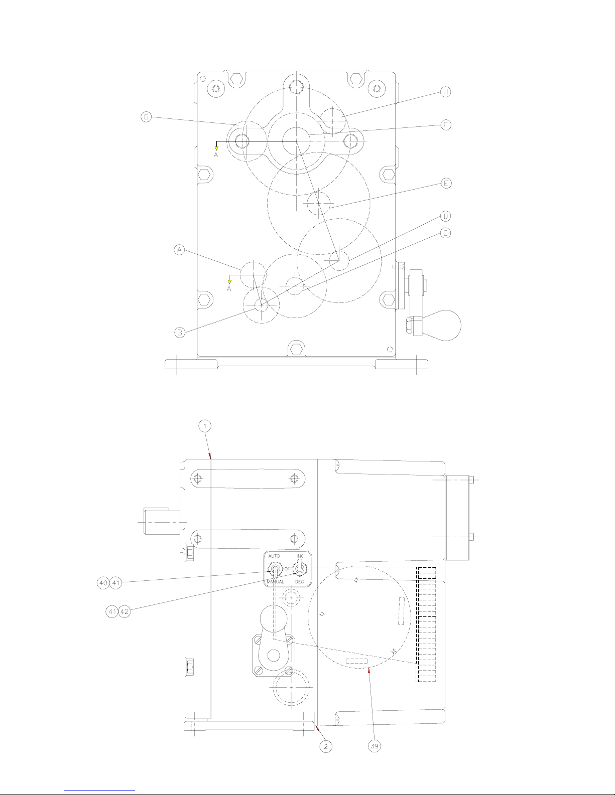
GEAR LOCATION
Front View
Letters in balloons
refer to gear
assembly drawing
on page 15.
Parts Identification
Side View
Numbers in balloons refer
to parts identification list
on pages 17-18.
14

Parts Identification
GEAR ASSEMBLY
Numbers in balloons refer to parts
identification list on pages 17-18.
15

Parts Identification
LIMIT SWITCH COMPARTMENT
Numbers in balloons refer to parts
identification list on pages 17-18.
16

Spare Parts List
Recommended Spare Parts Indicated in Bold
ID DESCRIPTION PART NUMBER QTY
1 Gasket, Gear Cover 13C-016024-001 1
2
3 Bushing (2nd Stage) 18B-SP1988-067 2
4 Bushing (3rd Stage) 18B-SP1988-007 2
5 Bushing (4th Stage) 18B-SP1988-068 1
6
7
8 Bearing (Output Shaft) 17B-003813-031 1
9 Bushing (Switch Shaft) 18B-SP1988-057 1
10
11 1
12
13
14 1
15 1
16
17
18
19
20
21
22 Woodruff Key #204 58B-016181-007 1
23
24 Handcrank 74A-016182-001 1
25 Lip Seal, Ha nd crank 19B -003815-017 1
26 Beari ng, Handcrank 17B-003813-011 1
Gasket, Rear Cover 13C-015754-001
Bearing (4th Stage) 17 B-003813-007 1
Bearing (4th Stage)* 17B-003813-077 1
Bearing (5th Stage) 17 B-003813-004 2
Bearing (5th Stage)* 17B-003813-083 2
Bushing (Output Shaft) 18B-003814-029 1
Bearing (Output Shaft)* 17B-003813-084 1
(See Motor Selection on p. 20)
Motor
Drag Brake Ass’y (ac)
(except 31/1800)
Drag Brake Ass’y (ac)
(31/1800 only)
Drag Brake Ass’y (dc) 68C-035339-00 2
Woodruff Key #202 58B-016181-001 1
Woodruff Key #404 58B-016181-009 1
Pi n i on Gear
Gea r Ass’ y
Gea r Ass’ y
Planetary Gear Ass’y
(4th Stage)
Planetary Gear Ass’y
4th Stage
Gea r Ass’ y
Gea r Ass’ y
Output Shaft Gear 16B-016030-001
O u tput Shaft Gear * 16B-036930-001
Woodruff Key #606 58B-016181-016 1
Key 0.25”square x 2’ long * 61B -010954-464 1
Output Shaft - Splined 62B-016028-001 1
Output Shaft - Keyed 62B-016029-001 1
Output S h aft - Splined * 62 B-036936-001 1
Output S h aft - Keyed * 62B-036935-001 1
Gear, Helical 16A-015674-001 1
Gear, Helical* 16A-015674-002 1
(See Gear Chart on page 20)
(2nd Stage) (See Gear Chart on page 20)
(3rd Stage)
(5th Stage)
(5th Stage)*
68C-035339-001
68C-038298-001
65A-016036-001
65C-016048-001
65B-036953-001
65A-016027-001
65A-016027-002
1
1
1
1
1
1
1
1
1
1
1
27 Worm Gear 16A-015673-001 1
28 Bushing 18B-SP1988-066 1
Capacitor 5 MFD (1710) 24B-029812-005 1
Capacitor 10 MFD (1720) 24B-029812-008 1
Capacitor 10 MFD (1730) 24B-029812-007 1
29
Capacitor 3 MFD (1750)(1790) 24B-029812-004 1
Capacitor 2 MFD (1770) 24B-029812-003 1
30
31 Thermal Switch 74A-02 35 65-001 1
32 “O” Ring 74B-012708-022 1
33 Gear, Feedback 16B-003804-100 1
34 Gear, Pot 16B-003803-096 1
35 Gear, Limit Switch 61A-025809-001 1
36 Woodruff Key #404 58B-016181-009 1
37
38
39
40 Selector Sw itch 46B-004053-319 1
41 Rubber Boot 46B-004053-320 2
42 Selector Sw itch 46B-004053-313 1
43
44 Resistor 10 ohm, 25W 33B-003852-205 1
45
46 Characterized Cam Set 68A-017793-005 2
47
48
Heater 120V, 30W 74A-016946-001 1
Heater 240V, 75W 74A-016946-002 1
Potentiometer, 1 K ohm 34B-033104-001
2 SPDT (AC units) 68D-0 21669-001 1
4 SPDT (AC units) 68D-0 21669-002 1
6 SPDT (AC units) 68D-0 21669-003 1
2 SPDT (DC units) 68D-021669-004 1
4 SPDT (DC units) 68D-021669-005 1
6 SPDT (DC units) 68D-021669-006 1
2 DPDT 68D-021669-007 1
4 DPDT 68D-021669-008 1
6 DPDT 68D-021669-009 1
AD-8130 Servo Amplifier 68C-035658-001
AD-8130/EC-10835
w/o 24 Vdc power supply**
AD-8130/EC-10835
with 24 Vdc pow er supply**
4-20 m A Transm itter 70A-019948-001
SPDT (AC unit) 46A-010017-001
SPDT (DC unit) 46A-010017-003
DPDT 46A-010017-002
Potentiometer 1K ohm Linear
(for cha racterized cam set)
LVDT
(for cha racterized cam set)
Torque Limit Switch
(not show n)
70C-035950-001 1
70C-035950-002 1
68C-015435-001 1
68C-019632-001 1
46B-004053-416 2
1
1
1
2
2
2
17

Motor, Motor Pinion Gear
& 2nd Stage Gear Assy. Selection
Model
SM-1710
SM-1715
SM-1720
SM-1790
SM-1730
SM-1740
Sh ift Time
(sec. )
12 61B-026406-004 16B -015633-001 65B-016034-001
24 61B-026406-004 16B -015633-003 65B-016034-003
48 61B-026407-001 16B -003806-015 65B-016034-005
12 23C-038332-001 16B-015633-001 65B-016034-001
24 23C-038332-001 16B-015633-003 65B-016034-003
48 23C-038333-001 16B-003806-015 65B-016034-005
31 61B-026406-003 16B -015633-004 65B-016034-008
60 61B-026407-002 16B -017896-001 65B-016034-007
12 61B-026406-003 16B -015633-001 65B-016034-001
24 61B-026406-003 16B -105633-003 65B-016034-003
48 61B-026407-002 16B -015633-015 65B-016034-005
16 61B-026404-001 16B -015633-003 65B-016034-003
31 61B-026405-001 16B -003806-015 65B-016034-005
40 61B-026405-001 16B -017896-001 65B-016034-006
Motor Part #
(Item 11)
Motor Pinion Ge ar
Part # (Ite m 14)
2nd Stage Gear Assy.
Part # (Ite m 15)
12 61B-026406-001 16B -015633-001 65B-016034-001
SM-1750
SM-1770
24 61B-026406-001 16B -015633-003 65B-016034-003
48 61B-026407-003 16B -003806-015 65B-016034-005
12 61B-026406-002 16B -015633-001 65B-016034-001
24 61B-026406-002 16B -015633-003 65B-016034-003
48 61B-026407-004 16B -003806-015 65B-016034-005
Note: Models with 12, 24 or 48 seconds shift time were previously rated 17, 34 and 67 seconds respectively.
18

LUBRICATION
Maintenance
Under normal service conditions the motor, gearing,
bearings, and parts are all pre-lubricated and should
not require periodic maintenance. If for any reason the
unit is disassembled in the field, all oilite bushings
should be resaturated with an SAE-10, non-detergent
oil and all gearing heavily coated with Amoco Rykon
Premium Grease #2 or equivalent grease. Care should
be taken to ensure that no foreign material is allowed
to become combined with the grease in the gear train,
which will cause premature failure. Keep gearbox
clean and dry.
DRAG BRAKE ADJUSTMENT
The drag brake serves two functions: a) to prevent
actuator from backdriving at maximum rated torque;
and b) to allow the motor shaft to slip when
handcranking and the output shaft load is in excess of
rated torque.
The drag brake was factory set and should not need
readjustment. If it does need adjustment:
1. Apply an overhung load, equal to the maximum
torque rating to the output shaft.
2. Loosen drag brake jam nut until the motor shaft
starts to backdrive.
TORQUE LIMIT SWITCH ALIGNMENT
The torque limit switches are factory set and field
adjustment is not advised unless proper test equipment is available. If adjustment must be done, use the
following procedure:
1. Load the output shaft with a known load which
matches the torque rating of the actuator in an
opposing direction for the switch being adjusted.
2. Apply power to the motor and run the actuator to
drive the opposing load.
3. Increase the load by 5% to 10% and adjust the set
screw (140C) to trip the torque switch.
4. Remove the 5% to 10% increase of load and the
switch should reset.
5. Load the actuator in the opposite direction and set
the other switch in the same manner.
NOTE: When looking at the torque limit switch
assembly as it is mounted in the actuator, the switch
on the top of the assembly controls the CW torque
and the switch on the bottom controls the CCW
torque. The torque should be set near equal for both
directions.
3. Tighten the drag brake jam nut just enough to
prevent backdriving.
4. While handcranking against the load, increase the
load until motor backdriving occurs.
When the actuator is driven into a torque condition
in the CW direction (looking at the output shaft), the
handcrank handle will move slightly outward. For
CCW direction the handle will pull slightly inward.
19

Maintenance
MOTOR REPLACEMENT
1. Disconnect all power to the actuator.
2. Remove screws, washers and rear cover.
3. Disconnect actuator output shaft from driven
device and remove actuator from mount.
4. Remove bolts, washers, and front gear case cover.
Note location of all gearing.
5. Remove motor pinion.
6. Remove brake assembly from top of motor.
7. Disconnect motor wires - note colors.
8. Remove motor.
9. Reverse the procedure to install new motor. (Clean
and regrease all gearing, check bushings and
bearings, lubricate bushings with SAE-10, nondetergent oil.)
10. Reinstall the actuator.
FEEDBACK POTENTIOMETER REPLACEMENT
A. One Turn Linear Potentiometer
1. Disconnect all power to the actuator.
2. Remove screws, washers, and rear cover.
3. Remove three screws holding potentiometer and
disc to housing.
4. Pull potentiometer and disc out of housing.
5. Measure location of gear from mounting disc to
farthest face of gear and note measurement.
6. Loosen set screws and remove gear.
7. Remove nut and washer holding potentiometer to
disc.
8. Cut shaft of new potentiometer to same length as
old.
9. Mount new potentiometer on disc, tighten potentiometer nut, install gear to measured dimension
from step 5.
POWER GEARING REPLACEMENT
1. Perform steps 1,3 & 4 of Motor Replacement.
2. Remove defective gear(s) and replace with new.
3. Ensure all gearing and oilite bushings are properly
lubricated as detailed above.
4. Install front cover and Reinstall actuator.
POSITION LIMIT SWITCH REPLACEMENT
1. Disconnect all power to the actuator.
2. Remove rear cover.
3. Remove two screws and washers from appropriate
switch on assembly.
4. Install new switch and transfer wires from old
switch one at a time.
5. No realignment should be necessary.
10. Install assembly in housing and tighten screws.
11. Using a 25 watt solder iron, remove wires from old
potentiometer one at a time and solder to corresponding terminals on new potentiometer.
12. Align potentiometer and install cover.
B. Characterized Potentiometer
1. Disconnect power and remove rear cover.
2. Remove three screws and pull potentiometer off of
pins.
3. Install new potentiometer and tighten screws.
4. Using a 25 watt solder iron, remove wires from old
potentiometer one at a time and solder to corresponding terminals on new potentiometer.
CAUTION - DO NOT USE EXCESSIVE HEAT
WHEN SOLDERING.
5. Align potentiometer and install cover.
C. LVDT Assembly Replacement
1. Same as Characterized Potentiometer replacement
above.
2. Align LVDT body for zero output (see alignment
procedure, characterized cam adjustment on page
12, step G).
20

Linkage Options
Damper Shaft
Actuator Shaft
NOTES:
1. Maximum total link length is specified to prevent
buckling under compressive load.
2. Adjustable drive arms are also available to allow
length to vary from 6 to 10 inches (152 to 254 mm).
In this case, the adapter-clevis has rod ball ends
with lubrication fittings.
3. Weight of all linkage components (including customer supplied schedule 40 pipe) must be taken
into consideration when calculating total actuator
torque requirements.
21

Fixed
Major Dimensions
Adjustable
NOTES:
1. The optional local toggle switches are located on this
surface.
2. The SM-1700 series actuators can be foot, face or side
mounted.
3. Overall depth is approximately 13 inches (330 mm) on the
SM-1715 three phase model.
4. The output shaft is available in a one inch (25.4 mm)
diameter with 1/4 inch (6.35 mm) square keyway, or with
the optional spline, as shown in upper right hand corner.
All connections
and adjustments
are inside
22

23

The dimensions in this manual are subject to change without notice and should not be used
for preparation of drawings or fabrication of installation mounting. Current installation
dimension drawings are available upon request.
JORDAN CONTROLS, INC.
5607 West Douglas Avenue
Milwaukee, Wisconsin 53218
Phone: (414) 461-9200
FAX: (414) 461-1024
E-Mail: jordan@jordancontrols.com
IM-0468 1/00
24
 Loading...