

Page 1
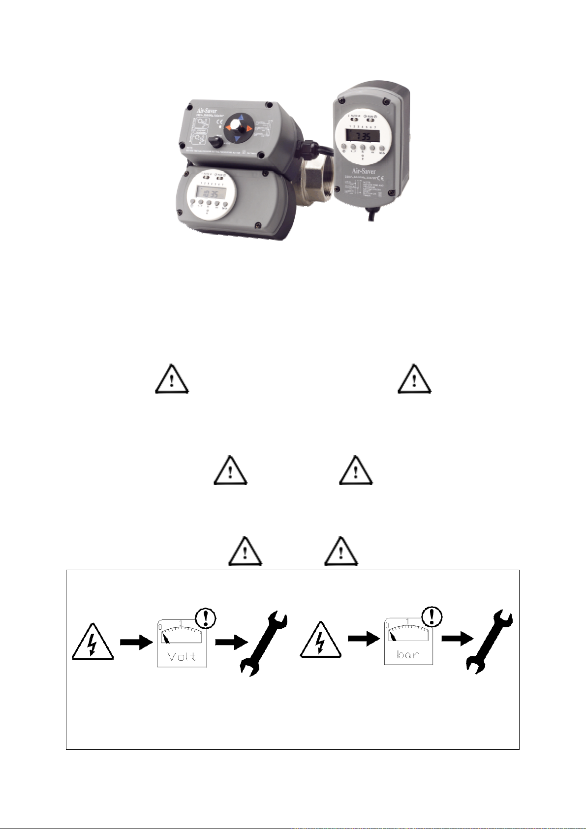
Air-Saver
Version: 0403
INDEX
Pa ge 1 Ge nera l sa fe t y instruc t io ns
Page 2 Installation instructions
Page 3 Programming instructions
Page 4 Programming instructions and specifications
Page 5 Connecting the external switch cable to the Air-Saver
Page 6 Connecting the external switch cable to the Air-Saver
Page 7 Maintenance and troubleshooting
SAFETY and PROPER USAGE
To ensure safe and enduring performance of this product, you must comply strictly with the instructions enclosed herein. Non-compliance
with instructions or improper handling of the prod uct will void your warranty! This prod uct is designed for use exclusively with types of
fluids or gasses as stated in its documentation. Usage of this product in conditions not specified in the product documentation or contrary to
the instr uct ions hereby provided is co ns idered IMP ROPER. The ma nufacturer w ill not be he ld liab le for any damages resulting fro m
improper use of the product.
ATTENTION
- Observe valid and generally accepted safety rules when planning, installing a nd using this product.
- Take proper measures to prevent unintentional operation of the product or damage to it.
- Do not attempt to d isas se mble this prod uct or lines in the s ystem w hile t hey are under pressure.
- Always turn off the voltage supply before working on the system.
Switch off the voltage supply before
installation or maintenance is carried out!
SAFETY
Depressurise the system before installation or
1
maintenance is carried out!
Page 2
INSTALLATION
IMPORTANT NOTICE
Before insta lling this prod uct make sure it comp lies w ith your request and that it suits your app licat io n!
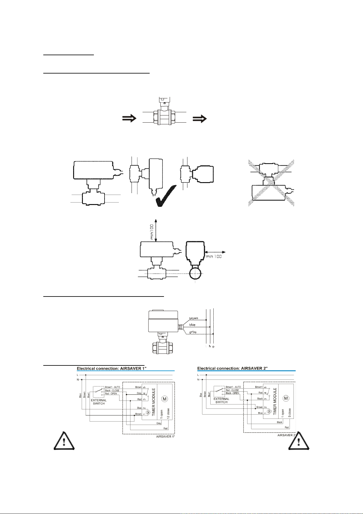
CONN ECTING TH E UNIT TO YOUR PIPELINE
· Make sure t hat no solid matter (e.g. sea ling compo und residue) gets into the va lve during the installation.
· Make sure that the pipeline is thoroughly clean.
· Use q uality sea ling compound only!
· Use a proper tool for fixing the valve! Ne ver use the actuator as a lever (do NOT apply any force on the actuator par t).
flow direction flow direction
_______________________________________________________________________________________________________
· Motorised Ballvalves usually operate in any mounting position. We recommend, however, that the va lve is mounted
according to these drawings.
______________________________________________________________________________________________________
· Minimum space required around the unit is 100 mm.
____________________________________________________________________
CONNECTING THE UNIT TO YOUR POWERSUPPLY
· Make sure that the supply voltage and frequency co mply with those stated on the product.
· Gro unding is required.
______________________________________________________________________________________________________
REMOTE WIRE CONNECTION DIAGRAMS:
NOTE:THE REMOTE SWITCHING WIRES ARE LIVE
WIRES AND CARRY 115VAC or 230VAC
2
Page 3
PROGRAMMING INSTRUCTIONS
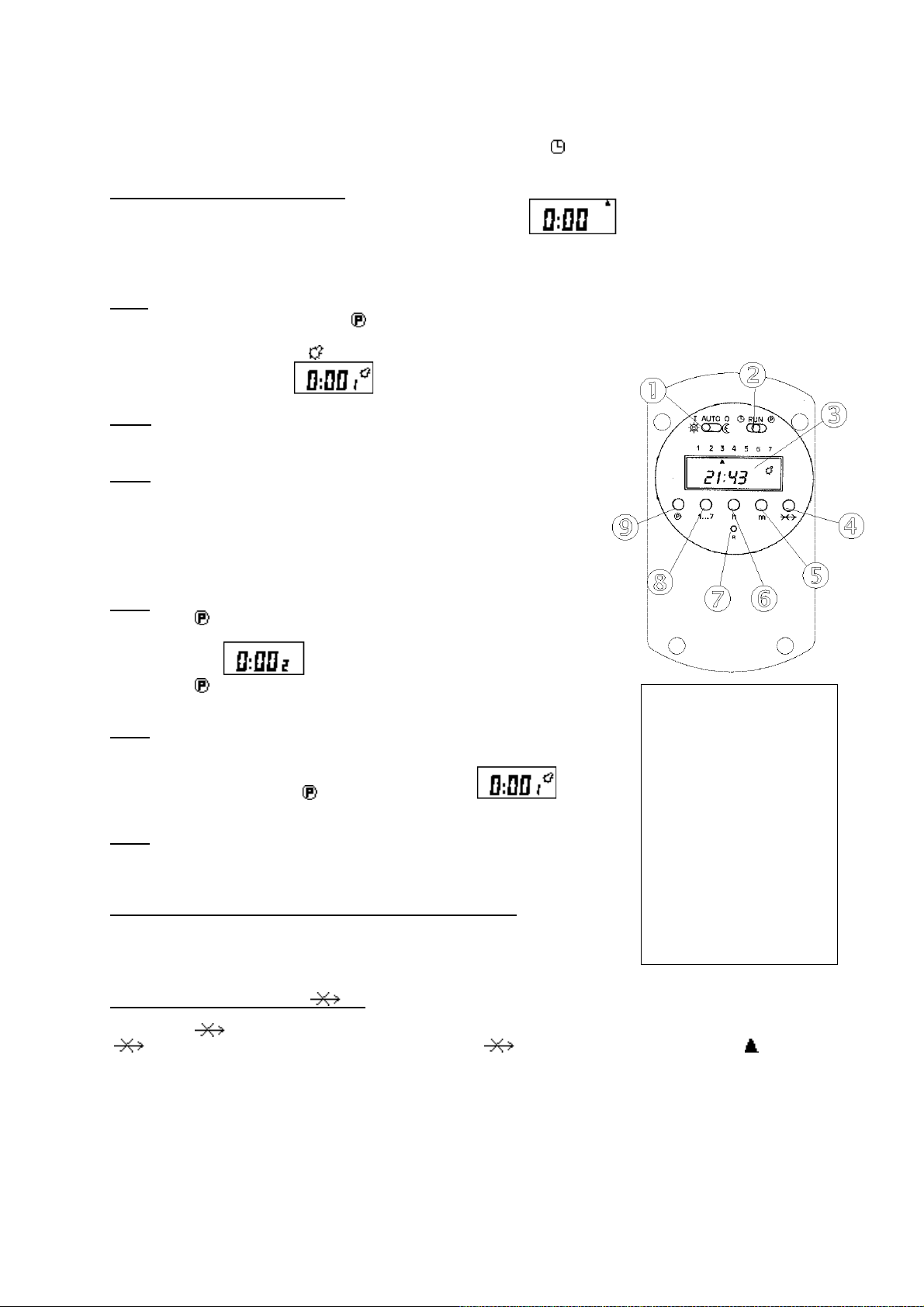
Before you start programming the unit, move the mode selector switch (2) in to position and shortly press the RESET (7) button to c lear
the existing program.
SETTING THE ACTUAL TIME AND DAY
1 After pressing the RESET (7) button, the display will look like this . All preprogrammed settings will be
2 You can set the actual time by pressing the [h] hours(6) a nd [m] minutes (5) , 24 hr display!
3 You can set the actual day by pressing the [1…7] button(8), (Mon=1, Tue=2, We=3…..).
1st Step
Move the mode selector switch (2) into position . The clock has 16 points: 8 x ON (OPEN the valve) and 8 x OFF (CLOSE the valve).
All odd (1,3,5 etc.) switch points open the valve, all even (2,4,6 etc.) switch points closes the valve. The switch points are numbered from 1
to 16. When programming the unit, the symbol will display when setting a valve open cycle.
When the following display appears yo u can e nter the firs t va lve ope n cyc le.
2nd Step
Enter the time you would like the valve to open by means of pressing the (h)hours (6) and
(m)minute (5) b uttons.
3rd Step
Set the day of the week when the valve should OPEN (by pressing [1…7]) (8).
- set the day (8) (Mon=1, Tue=2, We=3…..)
- Form time b locks Mon-Fri (1/2/3 /4/5 )
Mon-Sat (1/2/3 /4/5 /6)
Mon-Sun (1/2 /3/4/5/6/7 )
The day must be set otherwise the switching point will not be activated.
4th Step
By pressing the [ ] (9)key, you save the switching point data and go on to the next switching
point (CLOSE).
deleted. The unit is now ready to be programmed.
The d isp lay w ill s how . You can now set the time and day for closing the valve.
By pressing the [ ] (9)key, you save the switching point data and go on to the next switching point
(OPEN).
5th Step
To set the next OPEN and CLOSE cycle, please refer to step 3, 4 and 5.
To go to the next day, you must complete the 16 switching points (leave the unused switching points at
the value 0 :00 by simp ly press ing t he [ ] (9)key unt il the d isplay shows (3)).
Then select the next day a nd continue programming as described under step 3, 4 and 5.
6th Step
After you have finished programming the unit, move the mode selector switch 2 in to position RUN
And move mode se lector switch (1) in to position AUTO.
The unit will now operate fully automatically.
CHOOSING THE CORRECT WORKING MODE (Mode selector switch 1):
AUTO Unit will work b y means of it s program (a lso whe n using the re mote sw itc hing feat ure)
I Unit will OPEN valve perma nently ( i.e. after hours work s hift)
O Unit will CLOSE valve per ma nently (i.e. holiday facto r y shutdo wn)
PROGRAM OV ERR IDE BUTTON [ ] (4)
By pressing the [ ] (4) b utto n you will overr ide the p ro gram for this da y (meaning the valve will be closed fro m t he time yo u press the
[ ] (4) button , until 24:00 the same day. When in override mode the (4) symbol will be disp layed, a fter which the symbol
will be displayed ind icat ing the program mode per da y.
CONTROL PANNEL
1 Mode selector
switc h 1
(operation mode )
2 Mode selector
switch 2 (setting
time, program)
3 LCD display
4 Override button
5 Setting the
minutes
6 Se tt ing t he ho urs
7 RESET
8 Setting the days
9 Programming of
timer (sa ving
settings)
3
Page 4
USEFULL FEATURES
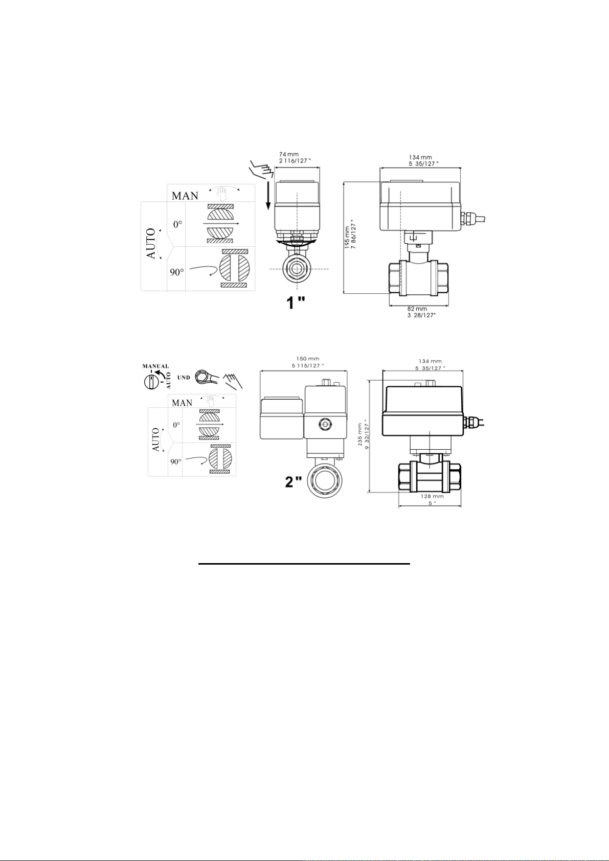
- You can manually open a nd close the valve by pushing the actuator towards the ballvalve and turning it left or right 90º
(a visual check on the valves pos ition can be done by checking the colour of the indicator:
RED = OPEN NONE or BLUE = CLOSED (See figure 1) (ONLY ON THE 1” VERSION)
- You can change t he position of the act uator on the valve b y turning the actuator (see figure 1).
Note. This will inf lue nce t he OPEN and C LOSE setting (OPEN w ill beco me C LOSE and C LOSE will beco me O PEN).
Air-Saver 1 ” ho us ing
Figure 1
Air-Saver 2 ” ho us ing
Figure 2
Note: On the 2” version (figure 2), you can manually open/close the valve by turning the knob on top of the actuator.
TECHNICAL SPECIFICATIONS
Power supply 115VAC or 230VAC (see label)
Power consumption 7W during the opening and closing of valve
Opening/closing time 30 seconds / 90º for the 1” version
105 seconds /90º for the 2” version
Max. ambient temp. 55ºC
Max. medi um temp. 100ºC
Max. pressure 16 bar / 230 psi
IP rating IP 54
Manual override Yes
Max. switching points 16 per day / 112 per week
Min. switching point 1 minute
Timer display 24 hrs
Timer battery live 1-2 years expected, not guaranteed
4
Page 5
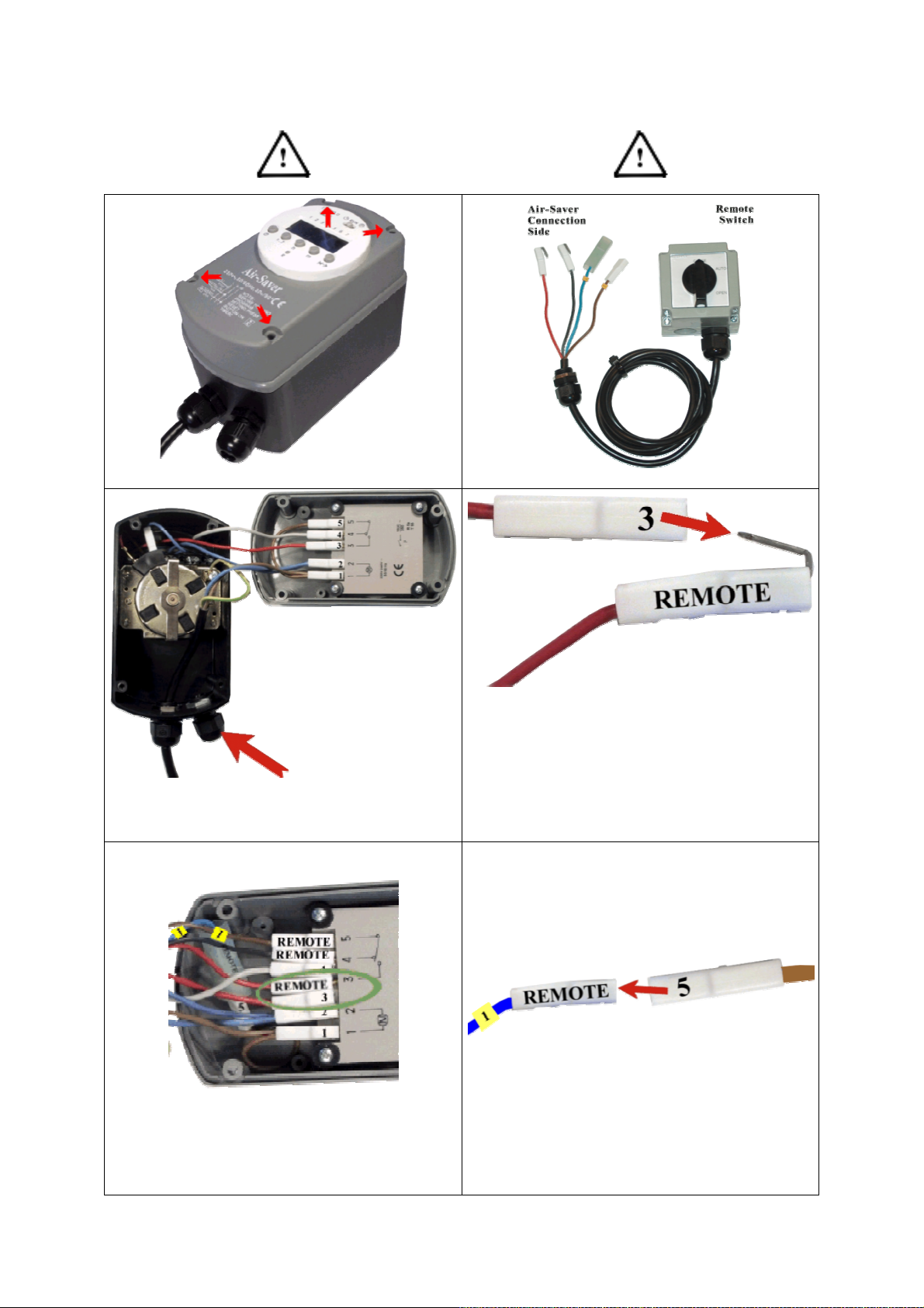
OPTION:
CONNECTING THE EXTERNAL SWITCHCABLE
TURN OFF ELECTRICAL SUPPLY
Unscrew the 4 screws to open the top cover
Slide the remote switchin g cable through
the cable gland
Identify the remote switching cable sides
Connect the RED remote cable with the RED
cable of point 3
Slide the RED cable back into its place
marked with the number 3
Connect the BLUE remote cable with the
BROWN cable of point 5
5
Page 6
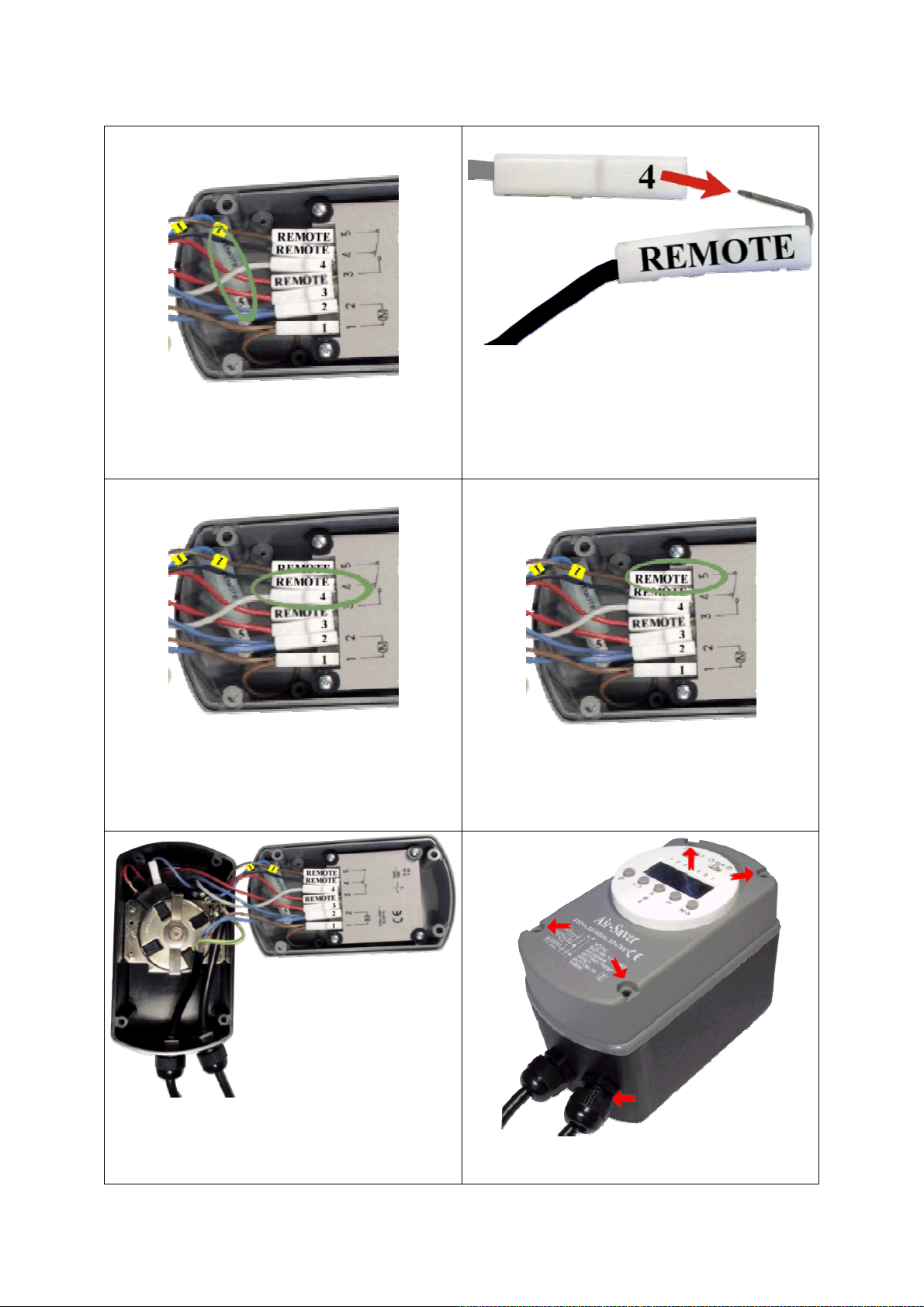
Hide the cable under the other cables
Connect the BLACK remote cable with the
GREY cable of point 4
Slide the BLACK/GREY cables back into its
place mark with the number 4
A complete look at the cable set-up
Slide the BROWN remote cable onto point 5
Tighten the 4 screws and the cable gland
6
Page 7
MAINTENANCE
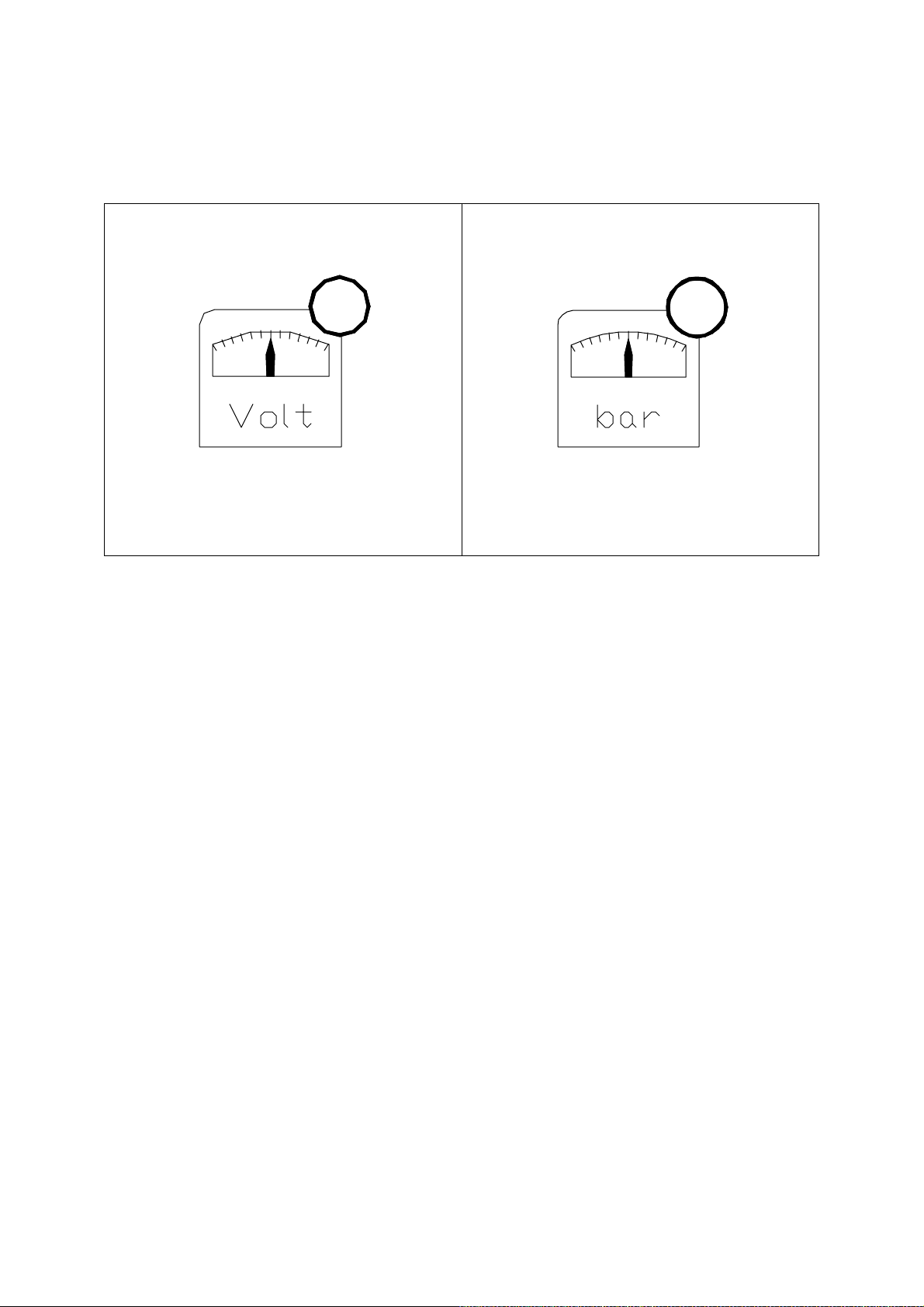
- Check battery in clock module (is the clock displaying the correct time?)
TROUBLESHOOTING
????
Check supply voltage
- Check whether the valve has been rotated manua lly! This could interfere with the programmed OPEN and CLOSE times, i.e. the OPEN
times could become the CLOSE times and visa versa.
Check pressure
????
7
 Loading...