


TEST 3
METER
EURORACK V/mA
TEST 3 BUILD INSTRUCTIONS
Test 3 is available as either a stand-alone circuit board for use on your workbench, or a module which can
be installed in your rack.
The Test 3 DIY Kit contains everything needed to build a functional module meter: a circuit board with
SMD parts pre-soldered, and just a few through-hole parts to hand-solder yourself.
If you want to mount Test 3 as a module, you’ll also need the Test 3 Front Panel Kit, which includes the
front panel and various pieces of mechanical hardware.
For instructions on how to use Test 3 after building it, the User Manual can be found at:
https://joranalogue.com/test3/manual
CONTENTS
Check if your kit includes all parts listed below. If anything is missing, please contact your dealer or
support@joranalogue.com.
DO-IT-YOURSELF KIT
Test 3 circuit board
Electrical parts bag
o 1 LED display
o 6 LEDs
o 2 tactile switches
o 2 16-pin shrouded headers
16-to-16-pin Eurorack power cable
FRONT PANEL KIT
Test 3 aluminium front panel
Mechanical parts bag
o 6 LED spacers
o 4 metal spacers
o 4 M3 nyloc nuts
o 4 M3 countersunk screws
o 2 mm hex key
2 switch caps (in separate bag)
Mounting hardware bag
o 2 black M3 screws
o 2 black nylon washers
o 2.5 mm hex key
1

TEST 3
METER
EURORACK V/mA
SOLDERING
Because Test 3 requires soldering just a handful of components, it’s a great starter kit if you’re just getting
into synth DIY. It will also help you to test and troubleshoot your future DIY projects.
Soldering is easy! Just keep the following things in mind:
If this is your first soldering project, ask a tech-savvy friend to assist you or visit a DIY soldering workshop
in your area. Also, many excellent soldering tutorials can be found online, such as this one by Dave
Jones from the EEVblog: https://youtu.be/fYz5nIHH0iY
Use a decent quality, temperature-controlled soldering station. These can be found very cheap.
Unregulated soldering irons which are plugged directly into the mains or gas soldering irons are not
suitable for electronics!
Use the biggest soldering iron tip you can. A bigger tip transfers the heat better, making soldering
quicker and easier. Chisel-shaped tips are preferred over conical tips.
1 mm tin/lead solder (Sn60Pb40) is recommended. Leaded solder is easier to use than lead-free solder,
and 1 mm is the ideal diameter for general through-hole soldering.
Clean your tip every few solder joints, using brass wool or a damp sponge. A dirty tip will not transfer
heat properly, making it hard to use.
When soldering a component, start by soldering one pin or two on opposite ends. Then check if the
part sits on the circuit board properly. If needed, you can still make adjustments by melting a solder
joint while applying pressure on the part, before soldering the rest of the pins.
The solder fumes do not contain lead, but are still not good for your health! Work in a well-ventilated
area. A solder fume extractor with filter is a good thing to have.
2
TEST 3
METER
!
EURORACK V/mA
BUILDING TEST 3
Before commencing construction, decide if you’ll use the Front Panel Kit, as there are some
differences and it is not easy to upgrade later.
Continue to page 6 if you are building Test 3 with the front panel.
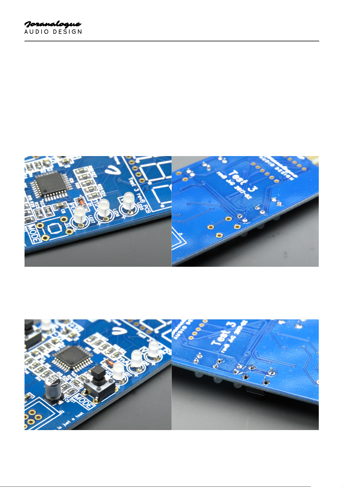
WITHOUT FRONT PANEL
The Test 3 circuit board already has all SMD parts pre-soldered, so you only need to solder the eleven
included through-hole parts. Apart from your soldering gear and flush side cutters, no additional tools are
required.
You will want to start with the physically lowest parts, which in this case are the six white LEDs. Insert
them all the way, and take care to solder them nice and straight. Also watch out for the polarity: the
longer lead is the positive side (anode). This pin should be next to the little plus sign on the circuit board,
which is always on the right. After soldering, clip the leads just above the solder joints. These are the only
leads that need to be clipped.
Next to solder are the two tactile switches. These simply snap in place and don’t have a particular
orientation.
3
TEST 3
METER
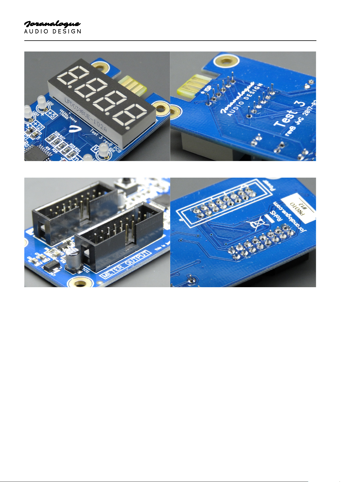
Insert and solder the LED display. Take note of the orientation again: the decimal points go on the bottom.
EURORACK V/mA
Finally, place and solder the two 16-pin shrouded headers. Both should be placed on the top side of the
circuit board. Again, check the orientation: the slot goes on the right. If you insert the included power
cable, the red stripe should go on the bottom. Be careful not to bump into the electrolytic capacitors
(silver cans) during placement.
4

TEST 3
METER
That’s it! Connect the left header (‘power supply’) to your Eurorack system with
the included cable and turn it on. The LEDs should light up, and you should be
able to measure the voltages of your system’s power supply.
This construction method leaves the mounting holes in the corners unused.
They each have a diameter of 3.2 mm, spaced 30 mm apart horizontally and 95
mm vertically. If needed, you can attach Test 3 to a non-conductive surface with
plastic PCB standoffs, M3 mounting hardware etc.
Enjoy!
EURORACK V/mA
5

TEST 3
METER
EURORACK V/mA
WITH FRONT PANEL
The build process is similar if you have the Front Panel Kit, with some minor differences. In addition to
your soldering gear, flush cutters and included hex keys, you’ll also need 5 and 5.5 mm nut drivers.
You will want to start with the physically lowest part, which in this case is the LED display. Insert it all the
way and solder all pins. Watch out for the polarity: the decimal points should be on the bottom. There’s
no need to clip the leads after soldering.
Next to solder are the two tactile switches. These simply snap in place and don’t have a particular
orientation.
6

TEST 3
METER
Place and solder the two 16-pin shrouded headers. The power supply header goes on the bottom, and
the module header on top. Again, check the orientation: in both cases, the slot goes on the right. If you
insert the included power cable, the red stripe should go on the bottom. Be careful not to bump into the
electrolytic capacitors (silver cans) during placement.
EURORACK V/mA
Now it’s time for the six white LEDs. Each of these has its own spacer, found in the Front Panel Kit. These
spacers bring the LEDs to the correct height for the front panel. They have two holes, one for each LED
lead, and a 1 mm deep cavity on top. Insert each LED into a spacer, taking care that each lead is in its own
hole and the LED sits in the cavity.
7

TEST 3
METER
Then insert the LED leads into the circuit board. Make sure the spacer sits nice and flat on the circuit
board, and the LED on the spacer. Also watch out for the polarity: the longer LED lead is the positive side
(anode). This pin should be next to the little plus sign on the circuit board. After soldering, clip the leads
just above the solder joints.
EURORACK V/mA
With the soldering done, only the mechanical assembly remains.
8

TEST 3
METER
Place the four metal spacers in the holes on the corners, and tighten the nyloc nuts on the back. Use the
5 mm nut driver for the spacers, and the 5.5 mm one for the nuts.
EURORACK V/mA
Place the switch caps on the tactile switches. Give them a good push to ensure they are inserted all the
way.
9

TEST 3
METER
The front panel can now be placed over the circuit board, and attached by way of the four countersunk
M3 screws. Screw these into the metal spacers using the small hex key (2 mm).
EURORACK V/mA
That’s it! Connect the rear header (‘power’) to your Eurorack system with the
included cable and turn it on. The LEDs should light up, and you should be able
to measure the voltages of your system’s power supply.
Now all that’s left is to install the Test 3 module in your case, using the included
mounting hardware.
Enjoy!
10

With compliments to the following fine people,
who helped to make Test 3 a reality!
Björn Jauss
Eric Lukac-Kuruc
Ģirts Ozoliņš
Jan D’Hooghe Jens Van Daele
Everyone at Wired Electronics
Boris Uytterhaegen
François Gaspard
Gregory Delabelle
Test 3 Build Instructions
version 2017-08-27
© 2017
info@joranalogue.com
https://joranalogue.com/
Designed & made in Belgium
 Loading...