


MORPH 4
DIMENSIONAL MODULATION ARRAY
INTRODUCTION
Modulation is the core concept of modular
synthesis: parameters changing over time,
adding movement and musical interest to what
would otherwise be merely static sounds. Being
able to control the amplitude of signals
throughout a patch is therefore essential, and
one can never have too many voltage controlled
amplifiers (VCAs).
Designed as a fully-featured modulation hub for
Eurorack synthesisers, Morph 4 takes the basic
concept of the multi-VCA module to the next
level.
Four linear amplitude modulators are controlled
by a master ‘morph’ parameter. The response of
each modulator to this parameter is completely
variable, both manually and under voltage
control, and can be overridden if desired. Each
response is triangular, with the ‘position’
parameter setting the maximum point along the
morph axis, while ‘span’ determines the width of
the triangle’s base.
CONTENTS
In the Morph 4 box, you’ll find:
Product card, stating serial number and
production batch.
16-to-10-pin Eurorack power cable.
Mounting hardware: two black M3 x 6 mm
hex screws, two black nylon washers and a
hex key.
The Morph 4 module itself, in a protective
cotton bag.
If any of these items are missing, please contact
your dealer or support@joranalogue.com.
In addition to separate signal inputs and outputs,
a variety of combined outputs is available as well:
A+B, C+D, add (unity gain) and averaging mixes,
and instantaneous minimum and maximum.
Input normalisation makes it easy to send the
same signal to multiple modulators, while
output and modulator response LEDs provide
essential visual feedback.
The combination of master control, fully flexible
modulators and multiple combined outputs
creates a module truly embodying the spirit of
‘patch programmable’ modular synthesis. Use
Morph 4 as a voltage controlled mixer, dual
crossfader, dual panner, interpolating scanner,
interpolating distributor, quad VCA,
quadraphonic controller, slope modifier, rectifier,
complex waveshaper or something in between
any of those—the choice is yours.
1
MORPH 4
DIMENSIONAL MODULATION ARRAY
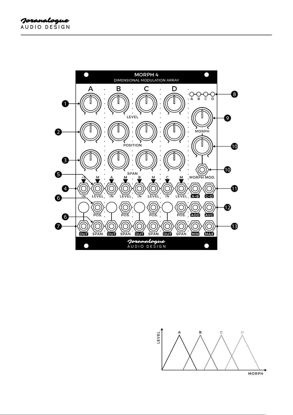
CONTROLS & CONNECTIONS
1 LEVEL KNOBS
The level knobs are control voltage (CV)
attenuators for the modulator level inputs,
determining the gain for each modulator.
2 POSITION KNOBS
Each modulator by default responds to the
morph parameter in a triangular fashion. The
position parameter sets the location of the
triangle’s peak in relation to the morph axis. For
example, if a position knob is set to the centre
position, that modulator will reach its peak
response when the morph knob is centred as
well (assuming no level CV is applied).
3 SPAN KNOBS
The width of the base for each modulator’s
morph response triangle is set by the span
parameter. For example, a small span means the
modulator will be fully closed for most morph
values, except for a small range around the peak
position.
2

MORPH 4
DIMENSIONAL MODULATION ARRAY
4 SIGNAL INPUTS
Connect your input signals to these sockets.
Input A has a +5 V normal, making it easy to use
Morph 4 to generate rather than process signals.
All other inputs are normalised from the
preceding one (A into B, B into C and C into D),
as indicated on the front panel, so the same
signal can be sent through multiple modulators.
Any kind of signal can be used: audio, CV or
gate/trigger.
5 LEVEL INPUTS
The level CV inputs provide linear voltage control
over the modulators. With the attenuator at
maximum, the response is 0 (−∞ dB) at 0 V, and
unity gain (0 dB) at +5 V. They can be made to
amplify when more than +5 V of CV is applied.
By default, these sockets are driven from the
triangular morph responses generated for each
modulator from its position and span
parameters. Plugging a socket into one of them
allows the corresponding modulator to be
controlled directly instead, overriding the morph
functionality.
6 POSITION AND SPAN INPUTS
Any voltage applied to one of these sockets is
added to the position/span set using the
corresponding modulator’s knob.
9 MORPH KNOB
The morph parameter is a kind of ‘macro control’,
affecting all channels simultaneously (except
channels where the level CV input is in use). How
the channels respond to different morph levels
depends entirely on their position and span
settings.
10 MORPH MODULATION INPUT AND KNOB
External modulation of the morph parameter is
possible using this input socket and polariser
knob. While the manual knob range is 0 to +5 V,
corresponding to the range of the channel
position knobs, external modulation can move
the morph value outside this range if desired.
11 SUMMING OUTPUTS
Two sub-mix outputs are available: one
combining channels A and B, and another
combining C and D. These are typically used for
(stereo) crossfading applications.
12 ADDER/AVERAGER OUTPUTS
These additional mixing outputs combine all
channels, useful for voltage controlled mixing
and scanning. They only differ in gain.
The adder output simply adds up all channel
output voltages at unity gain, most useful when
processing low-level signals.
7 SIGNAL OUTPUTS AND LEDS
The modulated signals are available directly from
these output sockets.
The LEDs show the real-time output voltages,
lighting up red for positive and blue for negative.
8 LEVEL LEDS
These LEDs visualise the incoming level CV for
each channel, determined either by the morph,
position and span parameters or the signal
applied directly to the level socket, before any
attenuation by the corresponding level knob.
The averager on the other hand lowers gain by
12 dB, avoiding clipping when processing
stronger signals.
13 MINIMUM/MAXIMUM OUTPUTS
The minimum and maximum output voltage
levels of the four channels are continuously
computed by analogue circuitry and made
available from these output sockets. They can
create surprising results for a wide variety of
input signals.
3

MORPH 4
DIMENSIONAL MODULATION ARRAY
PATCH IDEAS
HALF-WAVE/FULL-WAVE RECTIFICATION
The minimum/maximum outputs can be used to
separate out the positive and negative portions
of a signal (half-wave rectification). Apply your
signal to channel B, set to maximum level, while
setting all other level controls to their minimum
settings. ‘Disable’ morphing by setting the
positions fully counter-clockwise, spans
clockwise and morph itself counter-clockwise.
The minimum socket outputs the input signal’s
negative excursions, while the positive parts are
available from the maximum socket. Increase
the channel A level to move the ‘separation line’
from 0 to +5 V, or provide an input signal to
modulate it.
For full-wave rectification, apply an inverted copy
of the signal to channel C and set its level knob
to maximum as well.
WAVESHAPER
Rather than using the channels directly, plug an
audio signal into the morph input socket. As
channel A includes a +5 V input normal, various
new, often highly complex waveforms will be
made available from the mixing outputs, as
determined by the chosen input signal, morph
knob settings and the various level, position and
span parameters.
Not limited to audio use, this same technique
can be used to turn a simple CV source into an
advanced modulator. For bipolar output signals,
apply a constant −5 V to signal input C.
QUAD WINDOW COMPARATOR
With a low frequency or audio signal driving the
morph section and no other input signals
applied, it is possible to use Morph 4 as a quad
window comparator. Simply use the triangular
output waveforms from the four channels to
directly drive gate and/or trigger inputs
throughout your system.
For each channel, ‘position’ sets the window’s
centre, while ‘span’ determines the size.
Experiment with using the mixing outputs as
well, and modulation of the parameters. You
may need to process the output signals through
regular comparators first to drive certain inputs
reliably.
SYNCHRONISED VCAS
Within certain patches, it may be useful to have
an array of synchronised VCAs, all processing
different signals yet controlled by the same CV
source. The morph feature can be used to
provide this functionality.
To achieve this, set all position and span knobs to
their maximum settings, and the morph knob to
minimum. Patch the signal inputs and outputs
as required. Then connect your CV to the morph
modulation input and use the corresponding
knob to set the sensitivity. At maximum
sensitivity, each channel will be fully attenuated
at 0 V and provide unity gain at +5 V. If your
control signal exceeds this, lower the sensitivity
to match. Note that the responses are still
triangular, so pushing beyond the unity gain
point will result in attenuation.
4

MORPH 4
DIMENSIONAL MODULATION ARRAY
SPECIFICATIONS
MODULE FORMAT
Doepfer A-100 ‘Eurorack’ compatible module
3 U, 20 HP, 30 mm deep (inc. power cable)
Milled 2 mm aluminium front panel with nonerasable graphics
MAXIMUM CURRENT DRAW
+12 V: 110 mA
−12 V: 110 mA
POWER PROTECTION
Reverse polarity (MOSFET)
I/O IMPEDANCE
All inputs: 100 kΩ
All outputs: 0 Ω (compensated)
OUTER DIMENSIONS (H X W X D)
128.5 x 101.3 x 43 mm
SUPPORT
As all Joranalogue Audio Design products,
Morph 4 is designed, manufactured and tested
with the highest standards, to provide the
performance and reliability music professionals
expect.
In case your module isn’t functioning as it should,
make sure to check your Eurorack power supply
and all connections first.
If the problem persists, contact your dealer or
send an email to support@joranalogue.com.
Please mention your serial number, which can be
found on the product card or on the module’s
rear side.
REVISION HISTORY
Revision C: no functional changes.
MASS
Module: 240 g
Including packaging and accessories: 315 g
Revision B: initial release.
5

With compliments to the following fine people,
who helped to make Morph 4 a reality!
Ben ‘DivKid’ Wilson Björn Jauss
Boris Uytterhaegen Gregory Delabelle
Jan D’Hooghe Janus Coorevits
Jérémy Bocquet Jeroen De Pessemier
Lieven Stockx Marcin Staniszewski
Quincas ‘Synth DiY Guy’ Moreira Sebastiaan Tulkens
Morph 4 User Manual
version 2020-12-25
21st Century Analogue Synthesis—Made in Belgium
© 2020
info@joranalogue.com
https://joranalogue.com/
 Loading...