

Page 1
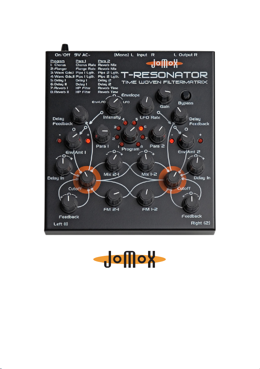
T-RESONATOR
TIME WOVEN FILTER MATRIX
Operating Manual
Page 2

Thank you for using the Jomox T-Resonator! We hope you will
enjoy this unique device and have lots of great fun with it.
“T“ stands for “Time“.
“The T-Resonator transforms timely events into an analog filter
feedback network.“
● What does that mean? The T-Resonator is a stereo filter made
with analog circuits and capable of feedback, with an integrated
stereo digital delay. The digital delay, which features analog
feedback loops, is literally “woven” into the circuits.
● The stereo filter contains every possible internal feedback path, all
controlled using the Feedback, Mix 1/2 and FM 1/2 controls, with a
dedicated knob for each of them.
● The filters are two 4-pole, 24 dB/octave transistor ladders made
entirely from discrete parts.
● 8 different chorus/delay/reverb algorithms can be chosen for the
delay section, which has 2 independent delay lines with different
delay times and feedbacks. The delay times extend from less than
1ms to 1 second, the actual range and structure depending on the
chosen algorithm.
● Moreover, the T-Resonator contains a sine wave LFO that can run
on its own or be shaped by the audio envelope. All aspects of the
LFO are controlled by a single knob. In the center position the
amount is zero, turning to the left controls audio-enveloped LFO,
and turning to the right controls LFO running freely.
● The sine LFO gets retriggered by the audio signal depending on
the input gain. The envelope is generated by an audio envelope
follower, and the LFO and envelope can be combined.
● Extremely versatile modulations are possible with this unique
structure.
● The delay feedback routes back from the outputs of the analog
filters into the analog inputs of the delay line.
● You can easily create seesaw analog echoes, “Klingon”alien insect
voices using extreme feedback or membrane-like sounds by “wave
guide” algorithm and many more.
● Because the feedback audio is analog, the resulting audio sounds
very organic. The screaming analog feedback can repeat itself via
delay and create new sound patterns by layering.
2
T-Resonator Operating Manual
Page 3

How to hook up the unit
Before connecting, please turn off all other devices.
On the back side of the T-Resonator you will find these connections:
Power supply:
Please connect the provided wall wart adapter to the 9V AC~ power
jack. If, for any reason, you cannot use the original wall wart
adapter, please take care to use an alternate current power supply
with 9V AC~ 500mA. Never use an AC/DC adapter as the TResonator might be damaged!
Audio inputs:
Please connect the audio signals to be processed here. If you only
need a mono signal, please use the input labelled (Mono) L.
The T-Resonator has Hi-Z (high impedance) inputs, allowing you to
plug in an instrument like an electric guitar or a bass directly to the
inputs without any loss in sound. The gain reserve is enough to
amplify a weak guitar signal to drive the filters. Unbalanced line
audio signals of practically every level can also be processed.
Audio outputs:
The output signals of both filters are split out here.
Caution: On some settings of filter feedback, extremely loud and
powerful bass signals or feedback sounds may occur that can
damage your speakers or ears! Please consider using a limiting
device or a lower mixing level!
T-Resonator Operating Manual
3
Page 4

User Interface Analog Section
Gain:
This adjusts the sensivity of the input. If the signal overloads the
input, all 8 LEDs of the program selection will light up. However, the
unit has considerable headroom and is quite resistive to
overloading. You can (ab)use the distortion of filters creatively
without having to fear that the T-Resonator will be damaged.
Bypass:
If this button is pressed, the processed signal is sent to the outputs.
If it is released, the input is sent directly to the output and all
processing is bypassed.
LFO Intensity:
Here you can tweak the intensity of the LFO/envelope signal. In the
center position, the intensity is zero. When you turn to the left, the
resulting modulation signal is a combination of audio envelope and
LFO. The envelope masks the LFO. So, the signal is dependent on
the input signal and the LFO.
Env+LFO
Envelope
Turning to the right controls the LFO running freely on its own, fully
independent of the audio signal.
LFO
4
T-Resonator Operating Manual
Page 5

The sine LFO wave is re-triggered by peaks in the audio signal. The
threshold itself is fixed, but it can be varied by the adjustment of
the Gain control.
LFO
AUDIO
Restart
LFO Rate:
This parameter controls the LFO frequency (period) and ranges from
approximately 0.15Hz (7sec) to about 22Hz (45ms).
If the LFO Rate is set very low and the LFO Intensity is turned to the
left, the envelope alone determines the resulting modulation signal,
so it is possible to seamlessly adjust between a pure envelope signal
and an LFO-modulated envelope signal.
LFO Rate small
Envelope
LFO Rate=0
Envelope
Env Amt 1:
This knob determines how the envelope signal modulates the cutoff
frequency of the left filter (Envelope Amount). In the center
position, the cutoff of the filter is not changed. As you turn it to the
right, the filter cutoff opens further, and the corresponding right
LED lights up. If you turn it to the left, the filter gets closed in the
rhythm of the envelope signal, and the left LED lights up.
The LEDs show the phase of the modulating signal. If LFO intensity
and Env Amount are set to high levels, both LEDs may light up
alternating on sine LFO. They light up in the rhythm of the phase of
the modulation signal.
T-Resonator Operating Manual
5
Page 6

Env Amt 2:
This operates exactly like Env Amt 1, but affects only the cutoff
frequency of the right filter.
Mix 2-1:
With this knob, you can mix the output signal of the right filter with
positive or negative phase into the left filter. At center position the
intensity is zero. Turning to the left increases the negative phase
feedback, and turning to the right increases the positive phase
feedback. Depending on the other parameters, even small
deviations from the midpoint may lead to rather extreme changes of
sound.
Mix 1-2:
This operates exactly like Mix 2-1, but with this knob, you can mix
the output signal of the left filter with positive or negative phase
into the right filter.
The two Mix knobs can bring some interesting results. When Mix 1-
2 and Mix 2-1 are turned in opposite directions, the outputs will be
out of phase with each other, resulting in very narrow band
screaming filters! On the other hand, setting the two knobs similarly
will create strong bass enhancements via phase doubling.
Experiment and have fun!
Cutoff:
These knobs change the corner frequency of both low pass filters.
The more either knob is turned to the left, the duller its signal will
become (as the high frequencies get filtered). The more either knob
is turned to the right, the more its filter will open up, and its signal
will become brighter.
However, other parameters may also affect the cutoff, i.e.
modulation. With the cutoff controls, you are just setting the basic
value on which the other modulations add or subtract.
6
T-Resonator Operating Manual
Page 7

Feedback:
Delay Feedbac k
In the center position there is no feedback. Turning to the right
resembles the regular resonance of a normal music filter. If you turn
it to the left though, the filter reaches a fairly unstable state by
positive feedback. Vibrations appear that are similar to LFOs, and in
extreme positions very deep bass tones can result.
Caution: On some settings, very deep and strong bass signals may
occur that might damage your speakers or ears if you are not using
a limiter in your audio path!
FM 2-1:
This knob controls the amount of frequency modulation from the
right filter output to the left filter cutoff frequency. Turned fully
counterclockwise, the amount is zero.
FM 1-2:
This is the same as FM 2-1, except that the left modulates the right
filter.
User Interface Digital Delay Section
The built-in digital stereo delay takes a part of the input audio signal
and passes it through its various delay, chorus or reverb algorithms.
The output signal from the delay can be fed into the filter with
positive or negative phase via the knobs Delay In (1+2). Then, the
knobs Delay Feedback (1+2) feed the analog signal from the filter
back into the analog input of the delay.
Prog
+
Audio L
LFO/Env
Au dio R
A/D
Delay I
Intens
A/D
Delay II
+
Delay Feedback
P1
D/A
P2
D/A
T-Resonator Operating Manual
+
-
Delay In
Delay In
+
-
Filter I
Analog
Fee dbacks
Filter II
Out L
Out R
7
Page 8

Program:
No.
Description
Para 1
Para 2
LFO/Envelope
Stereo Chorus
Program
Chorus
Rate
Reverb
Mix
Chorus
Intensity
Stereo Flanger
Program
F
Rate
Reverb
Mix
Flange Intensity
4 short wave pipes
(delay lines)
delay range 0.6
Pipe 1
length
Pipe 2
length
Pipe 3+4 length
6 short wave pipes
(delay lines)
octave and 5
Pipe 1
0.6
Pipe 2
0.3
Pipe 1
(weak)
2 equally long delays
3ms
Delay 1
Delay 2
One long delay +
one short delay
Delay 1
3ms
Delay 2
0.6
Reverb program 1
HP Filter
Reverb
Time
LP Filter
Reverb program 2
HP Filter
Reverb
Time
LP Filter
This knob chooses the delay program. One of 8 LEDs arranged in a
circle light up for the currently selected program. Both parameters
Para 1 and Para 2 have different functions and ranges for different
programs. Also, the LFO may modulate single parameters in
various programs.
Please find more information about the different programs in the
following table:
Program
1 Chorus /
Reverb
2 Flanger /
Reverb
3 Waveguide I
4 Waveguide II
5 Delay I
6 Delay II
7 Reverb I
8 Reverb II
Para 1 / Para 2:
These knobs adjust the values for the defined parameters in the
delay programs. Please note that in some programs the LFO
Intensity also has an effect on the delay program.
-0.5s
lange
-30ms
th
pipes
-30ms
-1s
-15ms
-60ms
-6 length
8
T-Resonator Operating Manual
Page 9

Delay In (1+2):
With these knobs, you can mix the output signal of each delay into
its corresponding filter with either positive or negative phase. In
center position the intensity is zero.
As described in section Mix 1-2, you can obtain interesting effects
using either phase cancellation or phase doubling of the two delay
lines.
Delay Feedback (1+2):
These knobs control the feedback from each filter output to the
input of the corresponding digital delay. Turned fully counter
clockwise, the amount is zero.
Quick Start Guide
Turn both Env Amounts, Mix 2-1, Mix 1-2 and the Feedback knobs
to the center position, and turn both FM knobs fully counter
clockwise. Turn Delay In on both sides to center position and select
Program 6 (Delay II), set LFO Intensity to 3 o’clock position, LFO
Rate to about 11 o’clock and Gain to center position.
If you apply a line level signal to the inputs and tweak the cutoff
knobs, the M-Resonator will act like a normal stereo low pass filter.
Now let’s look at the feedback knobs. A turn to the right produces
the expected filter resonance whistling, but in the opposite
direction, the knob creates a totally different reaction. At low
amounts you can hear an increase in bass until the filter starts to
create extremely deep vibrations like a bass tone. Welcome,
Godzilla!
Re-center them again to get a neutral position.
Turn both filter cutoffs to the center position. As soon as you turn
the Env Amt (envelope amounts) to the left, the filters start to open
and close in the rhythm of the LFO. You can watch the LFO on the
LEDs. If you turn Env Amt to the right, the phase of the LEDs (and
that of the filter cutoff) changes. Watch and hear the filters close
and open to the rhythm of the LEDs.
Now turn Delay In 1 (affecting the left hand filter) a little bit to the
left. You can hear the echoed input signal. With Delay Feedback you
can control the number of echoes and with Para 1, the delay time.
You can do the same for the right side, but it will sound different,
T-Resonator Operating Manual
9
Page 10

because in this particular program there is only a very short delay
on this side. So, just crank up Delay In and Delay Feedback on the
right filter. Now apply a little Mix 1-2 and Mix 2-1 in counter
directions, and the little box will already start to produce some
pretty weird sounds ;)
Most of the other knobs cause very complex interactions between
both filters and therefore it is not possible to describe these actions
in an easy way. They are very much dependent on the audio
material and knob settings relative to each other. Sometimes only a
very little change of one knob causes the whole sound to change
into something totally different.
At this point we would like to encourage you to tweak and twiddle
and experiment with this unique filter box. Note that the structure
of the stereo filter is symmetrical. So it is very interesting to create
”mirrored” knob settings that feed back signals in both ways and
form the 2 filters into a multi-resonant complex feedback machine.
Welcome to the wonderful world of the JoMoX T-Resonator!
Have fun!
And finally...
Service, tips and tricks:
JoMoX GmbH
Körtestr. 10
10967 Berlin / Germany
http://www.jomox.com
E-Mail mail@jomox.de
May you have lots of fun and success with creative twiddling on all
of our unique products!
Berlin, January 2008
Jürgen Michaelis
10
T-Resonator Operating Manual
 Loading...