

Page 1
T-RACKONIZER
EURO RACK FILTER MATRIX MODULE
Operating Manual
Page 2

Thank you for using the Jomox T-Rackonizer! We hope that you will enjoy
this unique device and have lots of fun with it.
The T-Rackonizer is the eurorack successor of our very sucessful TResonator which did very well over the past years. It has been the least
possible implementation of the former experimental filter network
synthesizer called „Resonator Neuronium“. The number of 6 nodes had
been reduced to only two filter nodes – but still this structure offers a
tremendous variety of sounds.
The module contains 2 analog T-ladder moog-like filters and a digital delay.
“T“ stands for “Time“.
“The T-Rackonizer transforms timely events into an analog filter feedback
network.“
● What does that mean? The T-Rackonizer is a stereo filter made with
analog circuits and capable of feedback, with an integrated stereo digital
delay. The digital delay, which features analog feedback loops, is literally
“woven” into the circuits.
● The stereo filter contains every possible internal feedback path, all
controlled using the Feedback and Mix 1/2 controls, with a dedicated knob
for each of them.
● The filters are two 4-pole, 24 dB/octave transistor ladders made entirely
from discrete parts.
● On the T-Rackonizer, the mix, feedback and cutoff controls can be CVcontrolled (CV = control voltage). Once you insert a CV cable into the CV
jacks, the corresponding internal control knob (e. g. Cutoff) acts as an
amount to the external CV. Without CV input, the control knobs work over
the full internal range.
On the mid-zeroed controls a voltage of 2.5 V represents the center
position. This only yields if the amount (= the corresponding control knob)
is fully turned clockwise.
● 8 different chorus/delay/reverb algorithms can be chosen for the delay
section, which includes 2 independent delay lines with different delay times
and feedbacks. The delay times extend from less than 1ms to 1 second,
the actual range and structure depending on the chosen algorithm.
● Also the program select can be CV-controlled. The control voltage is
added to the internal selection. If the range exceeds number 8, it rolls over
to program 1.
2 T-Rackonizer Operating Manual
Page 3

● Moreover, the T-Rackonizer contains a sine wave LFO that can run on its
own or be shaped by the audio envelope. All aspects of the LFO are
controlled by a single knob. In the center position the amount is zero,
turning to the left controls audio-enveloped LFO, and turning to the right
controls LFO running freely.
● The sine LFO gets retriggered by the audio signal depending on the input
gain. The envelope is generated by an audio envelope follower, and the
LFO and envelope can be combined.
● Extremely versatile modulations are possible with this unique structure.
● The delay feedback routes back from the outputs of the analog filters into
the analog inputs of the delay line.
● You can easily create seesaw analog echoes, “Klingon”alien insect voices
using extreme feedback or membrane-like sounds by “wave guide”
algorithm and many more.
● Because the feedback audio is analog, the resulting audio sounds very
organic. The screaming analog feedback can repeat itself via delay and
create new sound patterns by layering.
Caution: On some settings of filter feedback, extremely loud and powerful
bass signals or feedback sounds may occur that can damage your speakers
or ears! If you are not familiar with the device, please consider using a
limiting device or a lower mixing level!!
3 T-Rackonizer Operating Manual
Page 4
Installation
Please turn off the euro rack prior to the installation! On the backside of
the T-Rackonizer module you can find these connections:
4 T-Rackonizer Operating Manual
Page 5
Installation in the eurorack
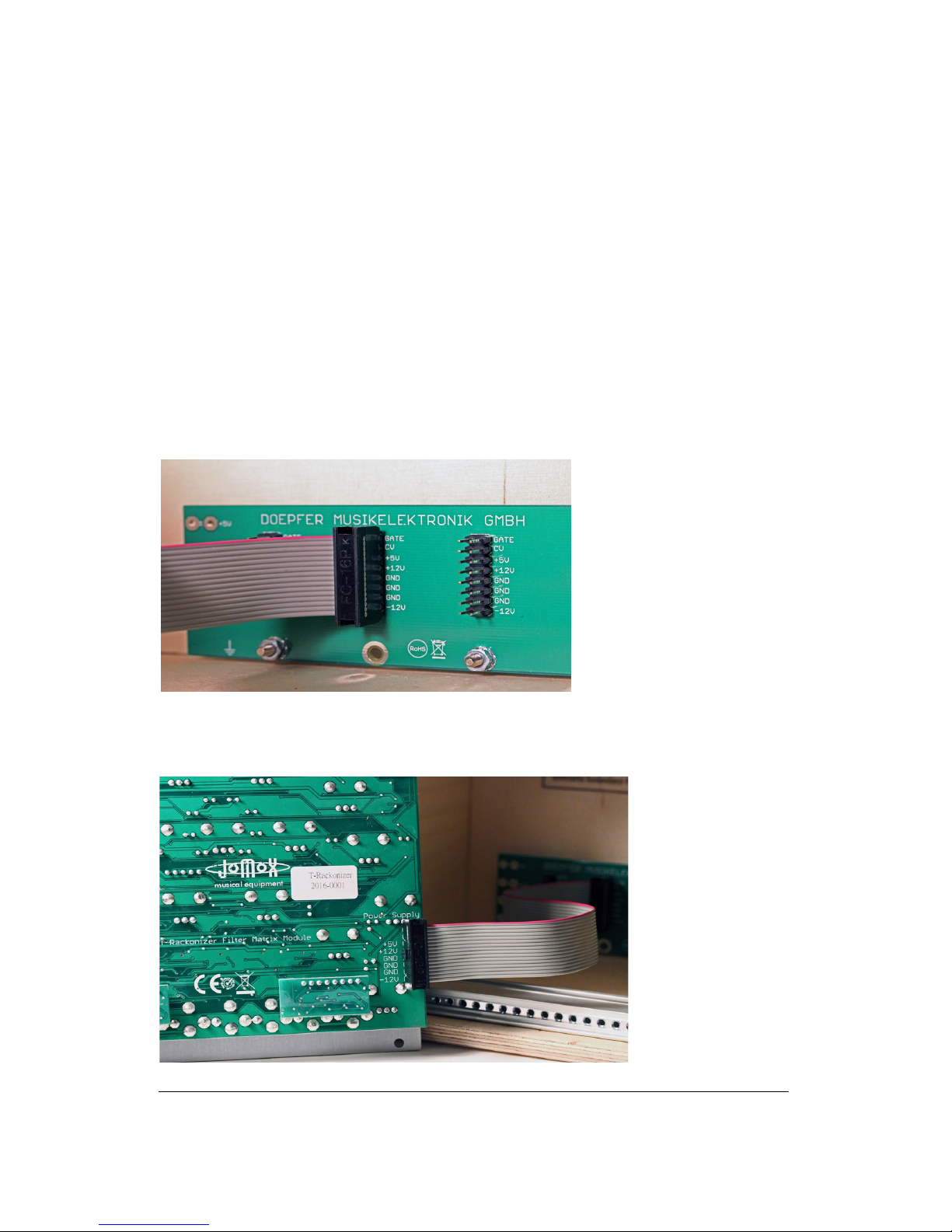
Please connect the supplied ribbon cable to the eurorack system bus rails
as shown on the pictures. The module needs +/-12 Volts at a supply
current of maximum 130mA on +12V and about 70mA on -12 Volts. The
optional 5 Volts and the CV/Gate on the A-100 Doepfer bus are both not
wired inside the Jomox module and not needed.
Other 10 pin systems may be used as well if only the lower part of the 16
pin connector is connected.
Please pay attention for the position of the voltages and the ground pins!
The printed voltages must match, please check the wires again and
make sure no pin is left or bent.
There are protection diodes inside the modules but please take extra care
to protect the rack and the module!
A-100 Doepfer bus. (The
Doepfer GmbH
enterprise and all of
their shown products are
registered trademarks.
With friendly approval of
Doepfer Musikelektronik
GmbH)
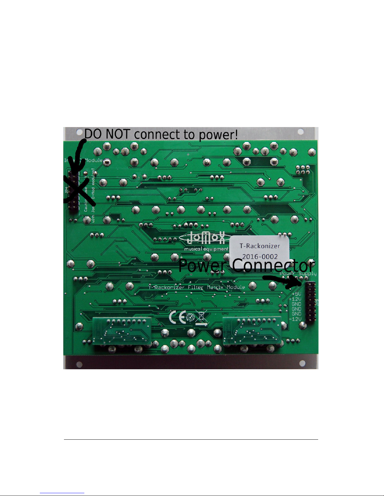
Jomox T-Rackonizer euro rack supply connector. Please connect the power
supply of the eurorack system bus here.
5 T-Rackonizer Operating Manual
Page 6
Attention: DO NOT connect, under any circumstances, the power
supply cable to the Jomox Inter-D-module bus!!! The rack power
supply and the module could get seriously damadged!
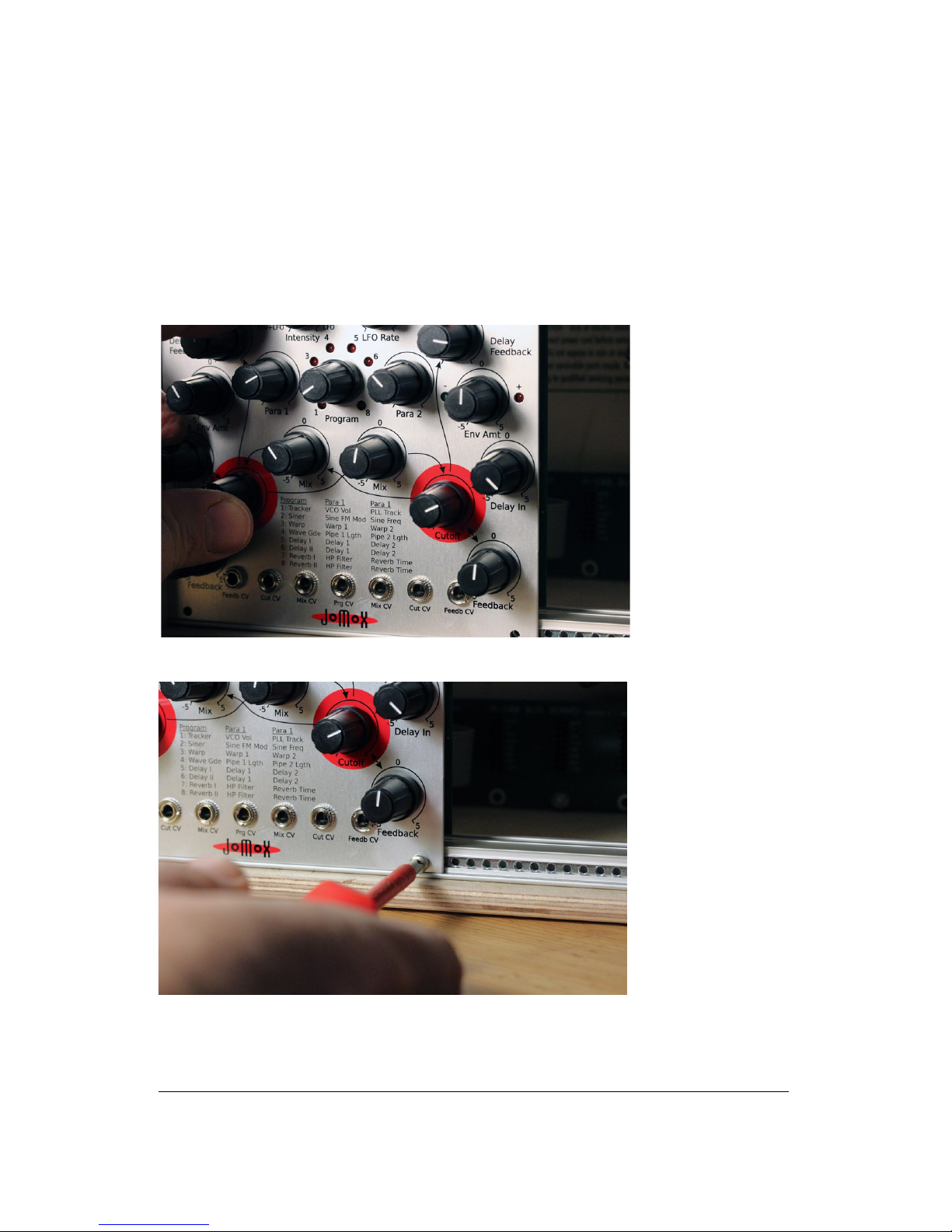
Then please mount the module on the rack rails using the supplied metric
M3 screws.
6 T-Rackonizer Operating Manual
Page 7

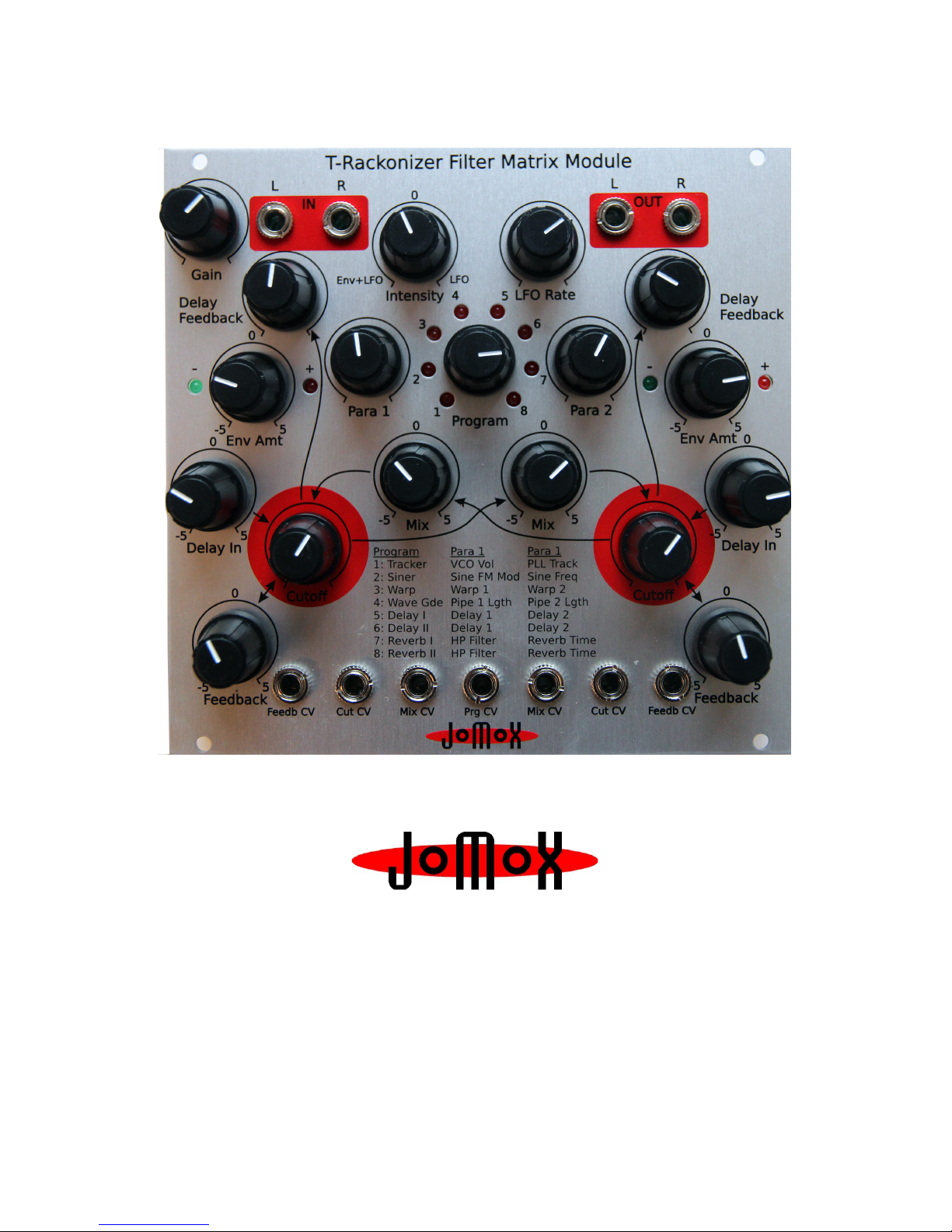
Audio inputs:
Please connect the audio signals to be processed here.
The T-Rackonizer has Hi-Z (high impedance) unbalanced inputs, allowing
you to plug in an instrument like an electric guitar or a bass directly
without any loss in sound. The gain reserve is enough to amplify a weak
guitar signal to drive the filters. Unbalanced line audio signals of almost
any level can also be processed.
Audio outputs:
The output signals of both filters are split out here.
7 T-Rackonizer Operating Manual
+
-
+
-
L
R
IN L
IN R
FX PROC
L
R
OUT R
OUT L
ENV
LFO
CUT
+
-
-
+
-
+
-
+
-
+
-
FEEDB MIX 2>1
FEEDB
MIX 1>2
DELAY IN
DELAY IN
CUT
+
-
CUTOFF
ENV AMT
ENV AMT
CUTOFF
PROG 1-8P1 P2
DELAY FEEDB
DELAY FEEDB
CV
CV CV
CV
CV
CV
CV
INT
RATE
FILTER
FILTER
T-RACKONIZER BLOCK DIAGRAM
GAIN
GAIN
IN OUT
Page 8
User Interface Analog Section
Gain:
This adjusts the sensivity of the input. If the signal overloads the input, all
8 LEDs of the program selection will light up. However, the unit has
considerable headroom and is quite resistive to overloading. You can
(ab)use the distortion of filters creatively without having to fear that the TRackonizer will be damaged.
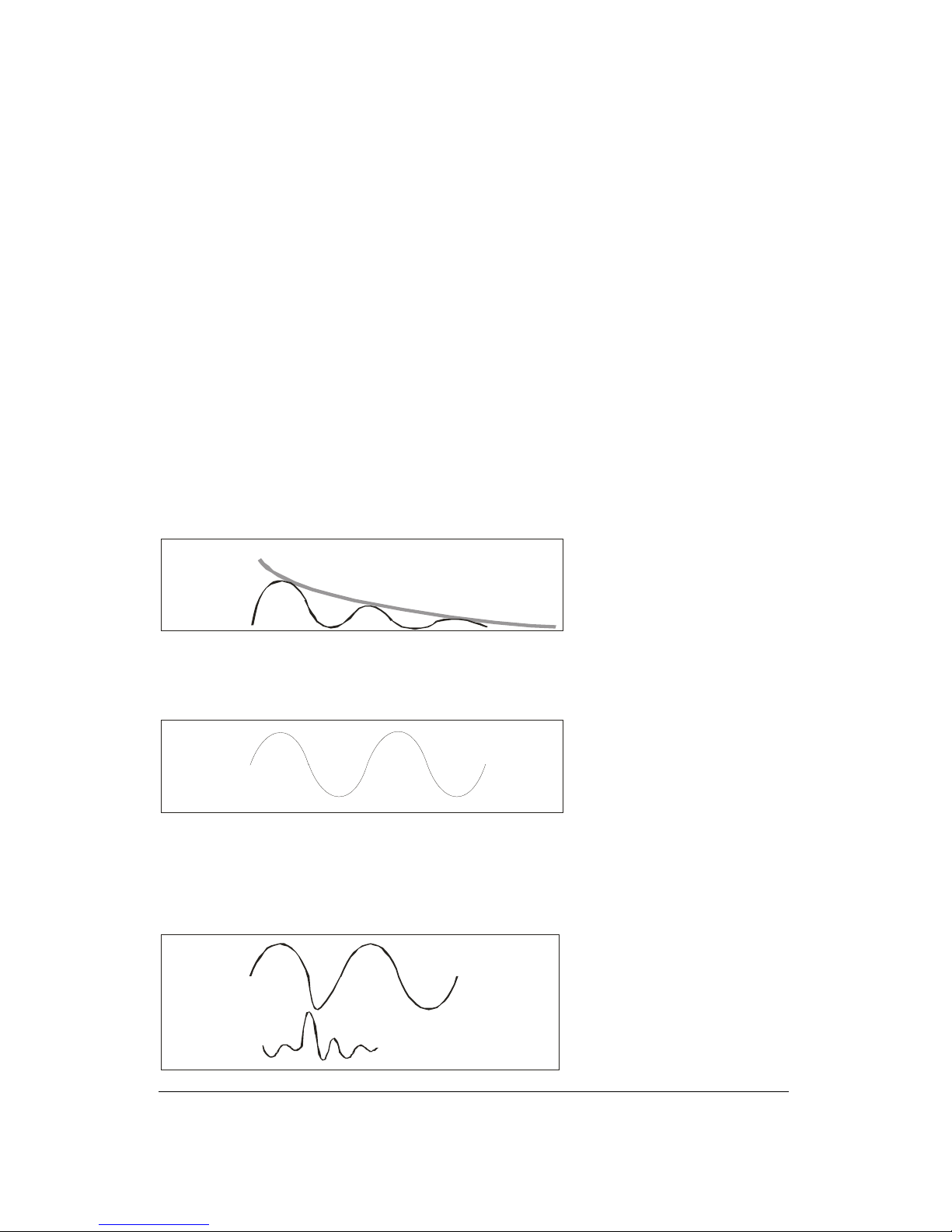
LFO Intensity:
Controls the intensity of the LFO/envelope signal. At center position, the
intensity is zero. When you turn to the left, the resulting modulation signal
is a combination of audio envelope and LFO. The envelope masks the LFO.
So, the signal is dependent on the input signal and the LFO.
E n v +L F O
E n v e lo pe
Turning to the right controls the LFO running freely on its own, fully
independent of the audio signal.
L F O
The sine LFO wave is re-triggered by peaks in the audio signal. The
threshold itself is fixed, but it can be varied by the adjustment of the Gain
control.
LF O
A U D I O
R e st ar t
8 T-Rackonizer Operating Manual
Page 9
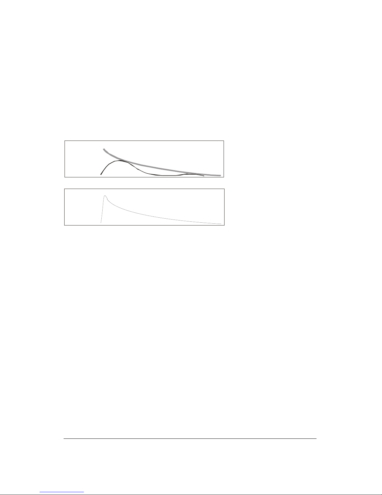
LFO Rate:
This parameter controls the LFO frequency (period) and ranges from
approximately 0.15Hz (7sec) to about 22Hz (45ms).
If the LFO Rate is set very low and the LFO Intensity is turned to the left,
the envelope alone determines the resulting modulation signal, so it is
possible to seamlessly adjust between a pure envelope signal and an LFOmodulated envelope signal.
L F O R a te s m a l l
E n v e lo pe
L FO R a te = 0
E n v e lo pe
Env Amt 1:
This knob determines how the envelope signal modulates the cutoff
frequency of the left filter (Envelope Amount). In the center position, the
cutoff of the filter is not changed. As you turn it to the right, the filter
cutoff opens further, and the corresponding right LED lights up. If you turn
it to the left, the filter gets closed in the rhythm of the envelope signal, and
the left LED lights up.
The LEDs show the phase of the modulating signal. If LFO intensity and
Env Amount are set to high levels, both LEDs may light up alternating on
sine LFO. They light up in the rhythm of the phase of the modulation
signal.
Env Amt 2:
This operates exactly like Env Amt 1, but affects only the cutoff frequency
of the right filter.
Mix 2-1:
With this knob, you can mix the output signal of the right filter with
positive or negative phase into the left filter. At center position the
intensity is zero. Turning to the left increases the negative phase
9 T-Rackonizer Operating Manual
Page 10

feedback, and turning to the right increases the positive phase feedback.
Depending on the other parameters, even small deviations from the
midpoint may lead to rather extreme changes of sound.
Mix 1-2:
This operates exactly like Mix 2-1, but with this knob, you can mix the
output signal of the left filter with positive or negative phase into the right
filter.
The two Mix knobs can bring some interesting results. When Mix 1-2 and
Mix 2-1 are turned in opposite directions, the outputs will be out of phase
with each other, resulting in very narrow band screaming filters! On the
other hand, setting the two knobs similarly will create strong bass
enhancements via phase doubling.
Experiment and have fun!
Cutoff:
These knobs change the corner frequency of both low pass filters. The
more either knob is turned to the left, the duller its signal will become (as
the high frequencies get filtered). The more either knob is turned to the
right, the more its filter will open up, and its signal will become brighter.
However, other parameters may also affect the cutoff, for example
envelope amount. With the cutoff controls, you are just setting the basic
value on which the other modulations add or subtract.
Feedback:
At center position there is no feedback. Turning to the right resembles the
typical resonance of a normal music filter. If you turn it to the left though,
the filter reaches a fairly unstable state by positive feedback. Vibrations
appear that are similar to LFOs, and in extreme positions very low bass
tones can result.
Caution: On some settings of filter feedback, extremely loud and powerful
bass signals or feedback sounds may occur that can damage your speakers
or ears! If you are not familiar with the device, please consider using a
limiting device or a lower mixing level!!
10 T-Rackonizer Operating Manual
Page 11

User Interface Digital Delay Section
The built-in digital stereo delay takes a part of the input audio signal and
passes it through its various delay, chorus or reverb algorithms.
The output signal from the delay can be fed into the filter with positive or
negative phase via the knobs Delay In (1+2).
Then, the knobs Delay Feedback (1+2) feed the analog signal from the
filter back into the analog input of the delay.
Program:
This knob chooses the delay program. One of 8 LEDs arranged in a circle
light up for the currently selected program. Both parameters Para 1 and
Para 2 have different functions and ranges for different programs. Also,
the LFO may modulate single parameters in various programs.
Please find more information about the different programs in the following
table:
No. Program Description Para 1 Para 2 LFO/Envelope
1 Tracker Audio VCO Tracker VCO
Volume
PLL
Tracking
Chorus
Intensity
2 Siner Sine Wave enveloped
+ modulated by Audio
Sine
Frequency
Input->FM
Modulation
Sine Amount
Envelope
3 Warp Audio VCO Tracker +
Pipes mixed to obtain
crazy effect
Pipe 1
length
Pipe 2
length
Pipe 3+4 length
4 Waveguide 4 short wave pipes
(delay lines)
delay range 0.6-30ms
Pipe 1
0.6-30ms
Pipe 2
0.3-15ms
Pipe 3+4 length
5 Delay I 2 equally long delays
3ms-0.5s
Delay 1 Delay 2
6 Delay II One long delay +
one short delay
Delay 1
3ms-1s
Delay 2
0.6-60ms
7 Reverb I Reverb program 1 HP Filter Reverb
Time
LP Filter
8 Reverb II Reverb program 2 HP Filter Reverb
Time
LP Filter
11 T-Rackonizer Operating Manual
Page 12

Para 1 / Para 2:
These knobs adjust the values for the defined parameters in the delay
programs. Please note that in some programs the LFO Intensity also has
an effect on the delay program.
Delay In (1+2):
With these knobs, you can mix the output signal of each delay into its
corresponding filter with either positive or negative phase. In center
position the intensity is zero.
As described in section Mix 1-2, you can obtain interesting effects using
either phase cancellation or phase doubling of the two delay lines.
Delay Feedback (1+2):
These knobs control the feedback from each filter output to the input of the
corresponding digital delay. Turned fully counterclockwise, the amount is
zero.
12 T-Rackonizer Operating Manual
Page 13

CV Controlled Parameters
Opposing to the T-Resonator, the T-Rackonizer uses a CV (control voltage)
for the most important control knobs. The signal is not being attenuated by
a potentiometer but by a VCA (voltage controlled amplifier) and uses a CV
for operation. Therefore, the internal control knobs only apply a CV to the
circuitries.
If you insert a plug into the corresponding jack, the external CV is
attenuated by the control knob, which makes them act as an amount to the
external CV. See diagram:
Feedback CV:
Please keep in mind that the internal Feedback knob is an amount to the
external CV once you have plugged in a CV cable.
As Feedback is a dual polarity control, the internal CV needs to reach 2.5
Volts for Feedback center position (=zero). This can be achieved if you turn
up the internal control knob fully clockwise. With a CV range of 0..5 V you
can now go through every position of the Feedback parameter.
However, if you only turn up the knob halfway to center position, you
would need to apply 5V to reach the center position and 10V to go across
into the positive area. As most CV sequencers only deliver 0 to 5 Volts you
need to open the Feedback knob fully clockwise to have the full control
range.
13 T-Rackonizer Operating Manual
CV 0-5V
UNPLUGGED: CUTOFF
PLUGGED: CV AMOUNT
CV INPUT DIAGRAM
5V
CV JACK
POTENTIOMETER
TO CIRCUIT
Page 14

Cutoff CV:
Please keep in mind that the internal Cutoff knob is an amount to the
external CV once you have plugged in a CV cable.
If you turn up the Cutoff control knob fully clockwise, the CV range goes
from 0..5 V. However, if you only turn up the Cutoff knob halfway, you
would need a CV range of 0 to 10V to have the full range. Most CV
sequencer's CV ranges are limited to 5 Volts though.
Mix CV:
Please keep in mind that the internal Feedback knob is an amount to the
external CV once you have plugged in a CV cable.
As Mix is a dual polarity control, the internal CV needs to reach 2.5 Volts
for Mix center position (=zero). This can be achieved if you turn up the
internal control knob fully clockwise. With a CV range of 0..5 V you can
now go through every position of the Mix parameter – which is important
as the mix parameter can cause severe feedback and screaming sounds if
not smoothly adjusted.
However, if you only turn up the knob halfway to center position, you
would need to apply 5V to reach the center position and 10V to go across
into the positive area. As most CV sequencers only deliver 0 to 5 Volts you
need to open the Mix knob fully clockwise to have the full control range.
14 T-Rackonizer Operating Manual
Page 15

Quick Start Guide
Turn both Env Amounts, Mix 2-1, Mix 1-2 and the Feedback knobs to the
center position. Turn Delay In on both sides to center position and select
Program 6 (Delay II), set LFO Intensity to 3 o’clock position, LFO Rate to
about 11 o’clock and Gain to center position.
If you apply a line level signal to the inputs and tweak the cutoff knobs, the
M-Resonator will act like a normal stereo low pass filter.
Now let’s look at the feedback knobs. A turn to the right produces the
expected filter resonance whistling, but in the opposite direction, the knob
creates a totally different reaction. At low amounts you can hear an
increase in bass until the filter starts to create extremely deep vibrations
like a bass tone.
Welcome, Godzilla!
Re-center them again to get a neutral position.
Turn both filter cutoffs to the center position. As soon as you turn the Env
Amt (envelope amounts) to the left, the filters start to open and close in
the rhythm of the LFO. You can watch the LFO on the LEDs. If you turn Env
Amt to the right, the phase of the LEDs (and that of the filter cutoff)
changes. Watch and hear the filters close and open to the rhythm of the
LEDs.
Now turn Delay In 1 (affecting the left hand filter) a little bit to the left.
You can hear the echoed input signal. With Delay Feedback you can control
the number of echoes and with Para 1, the delay time.
You can do the same for the right side, but it will sound different, because
in this particular program there is only a very short delay on this side. So,
just crank up Delay In and Delay Feedback on the right filter. Now apply a
little Mix 1-2 and Mix 2-1 in counter directions, and the little module will
already start to produce some pretty weird sounds ;)
Most of the other knobs cause very complex interactions between both
filters and therefore it is not possible to describe these actions in an easy
way. They are very much dependent on the audio material and knob
settings relative to each other. Sometimes only a very little change of one
knob causes the whole sound to change into something totally different.
At this point we would like to encourage you to tweak and twiddle and
experiment with this unique filter box. Note that the structure of the stereo
filter is symmetrical. So it is very interesting to create ”mirrored” knob
settings that feed back signals in both ways and turn the 2 filters into a
multi-resonant complex feedback machine.
15 T-Rackonizer Operating Manual
Page 16

Welcome to the wonderful world of the JoMoX T-Rackonizer!
Don't get discouraged too soon – we believe that we have created a little
instrument of its own that wants to be learned and rehearsed. It rewards
you with a bunch of really organic sounding weird sci-fi sounds that would
require a lot more of modules and efforts if patched from single modules.
And finally...
Service, tips and tricks:
JoMoX GmbH
Körtestr. 10
10967 Berlin / Germany
http://www.jomox.com
E-Mail mail@jomox.de
May you have lots of fun and success with creative usage on all of our
products!
Berlin, January 2016
Jürgen Michaelis
16 T-Rackonizer Operating Manual
Page 17

T-RACKONIZER
EURO RACK FILTER MATRIX MODUL
Bedienungsanleitung
Page 18

Wir freuen uns, dass Sie sich für einen T-Rackonizer von Jomox
entschieden haben und wünschen Ihnen viel Freude mit dem Gerät!
Der T-Rackonizer ist die Euro-Rack Version unseres äußerst erfolgreichen
T-Resonators, der sich in den letzten Jahren sehr gut verkauft hat. Er war
ursprünglich die kleinste mögliche Implementierung des experimentellen
Filternetzwerk-Synthesizers namens „Resonator Neuronium“. Die Zahl von
sechs Knoten wurde auf zwei Filterknoten begrenzt, und trotzdem bietet
diese relativ einfache Struktur eine unglaubliche Vielzahl von Sounds.
Das Modul enthält 2 analoge Moog-ähnliche Filter und einen digitalen
Effektchip.
„T“ steht für „Time“.
„Der T-Rackonizer transformiert zeitliche Vorgänge in ein analoges
rückgekoppeltes Filternetzwerk.“
● Was bedeutet das? Der T-Rackonizer ist ein aus analoger
Schaltungstechnik aufgebautes rückkoppelbares Stereo-Filter mit einem
integriertem Stereo Digital Delay. Das Delay ist mit ebenfalls analogen
Rückkoppelungsschleifen in die Schaltung „eingewebt“.
● Das Stereo-Filter hat alle erdenklichen Rückkoppelungswege wie
Feedback und Mix1/2, die alle über eigene Potis eingestellt werden können.
● Die Filter sind zwei 24-pol Transistorkaskaden Tiefpassfilter, die
vollständig aus diskreten Bauteilen aufgebaut sind.
● Beim T-Rackonizer sind die Feedback-, Mix- und Cutoff-Regler als CVs
(CV = Control Voltage = Steuerspannung) ausgeführt. Sowie man einen
Stecker in die betreffende CV-Buchse steckt, arbeitet der interne Regler als
Amount für die eingehende CV. Ohne CV-Stecker arbeiten die internen
Regler über den gesamten CV-Bereich (0-5 Volt).
Bei den mittensymmetrischen Parametern wie Feedback und Mix ist die
Mittelstellung Null. Dies entspricht intern einer CV von 2.5 Volt, die man
am besten erreichen kann, wenn der interne CV-Regler voll aufgedreht ist.
● Für die Delay-Sektion können 8 verschiedende Chorus/Delay/Reverb
Algorithmen ausgewählt werden, bei denen jeweils 2 unterschiedliche
Delay Lines mit unterschiedlichen Zeiten und Feedbacks eingestellt werden
können.
Delays reichen von unter 1 ms bis zu einer Sekunde, der Bereich und die
Struktur sind abhängig vom ausgewählten Algorithmus.
● Auch die Programmauswahl kann über CV gesteuert werden. Die
Steuerspannung wird zu der internen Programmauswahl hinzu addiert.
Wenn der Regelbereich über das Programm 8 hinausgeht, springt die
Auswahl wieder auf Programm 1 über.
T-Rackonizer Bedienungsanleitung
18
Page 19

● Ferner enthält der T-Rackonizer noch einen Sinus-LFO, der sowohl
freilaufend sein kann als auch mit der Audio-Hüllkurve überlagert werden
kann. Alles wird über einen einzigen Regler eingestellt. In der
Mittenposition ist das Amount 0, nach links ist es Hüllkurve mit LFO, nach
rechts LFO allein.
● Der Sinus-LFO wird durch das Audiosignal neu getriggert, abhängig vom
eingestellten Input Gain. Die Hüllkurve wird durch einen Envelope Follower
aus dem Audiosignal generiert. LFO und Hüllkurve können kombiniert
werden.
● Extrem umfangreiche Modulationsmöglichkeiten sind durch diese
einzigartige Struktur möglich.
● Das Delay-Feedback geht über die Ausgänge der analogen Filter zurück
in die Analogeingänge der Delay Line.
● Damit können sich aufschaukelnde Analog-Echos, „Klingonen-Parties“
durch extremes Feedback oder saitenähnliche Sounds durch den „Wave
Guide“ Algorithmus und vieles mehr erzeugt werden.
● Durch die analoge Rückkoppelung klingt alles organisch.
Die kreischenden Analog-Feedbacks können sich selbst delayen und dabei
neue Soundpattern bilden.
Vorsicht! Bei bestimmten Einstellungen der Filter-Feedbacks kann es zu
extrem lauten Bass-Signalen oder Rückkoppelungen kommen, die unter
Umständen Ihre Lautsprecher oder Ihre Ohren schädigen könnten! Wenn
Sie unerfahren in der Bedienung des T-Rackonizers sind, dann verwenden
Sie bitte einen Limiter oder leisere Einstellungen!
T-Rackonizer Bedienungsanleitung
19
Page 20

Installation
Schalten Sie vor dem Einsetzen des Moduls das Eurorack aus! Auf der
Rückseite des T-Rackonizers finden Sie folgende Anschlüsse:
T-Rackonizer Bedienungsanleitung
20
Page 21

Installation im Euro-Rack
Schließen Sie das mitgelieferte Flachbandkabel an die Euro-Rack
Systembus-Schiene wie auf dem Bild angezeigt an. Das Modul benötigt +/12 Volt bei einer Stromaufnahme von maximal 130mA an +12V und etwa
70mA an -12V. Die beim A-100 Doepfer-Bus optionalen +5 Volt und das
CV/Gate über den Bus sind im Jomox-Modul nicht verdrahtet und werden
nicht benötigt. Andere 10-pin Systeme können verwendet werden, wenn
nur der untere Teil des 16-Pin Steckers bestückt wird.
Bitte beachten Sie die Lage der Spannungen und der Ground-Pins! Die
Spannungen müssen übereinstimmen. Bitte überprüfen Sie den Anschluss
noch einmal, bevor Sie das Rack einschalten.
A-100 Doepfer-Bus. (Die
Fa. Doepfer und alle ihre
hier gezeigten Produkte
sind eingetragene
Warenzeichen. Mit
freundlicher
Genehmigung der
Doepfer Musikelektronik
GmbH).
Jomox T-Rackonizer Euro-Rack Supply Stecker. Bitte schließen Sie hier die
Stromversorgung vom Euro-Rack Systembus an.
Achtung: bitte schließen Sie auf keinen Fall das Versorgungskabel
an den Inter-D-Module Bus an!!! Die Stromversorgung und das
Modul könnten ernsthaft Schaden nehmen!
T-Rackonizer Bedienungsanleitung
21
Page 22

Dann montieren Sie das ganze Modul auf den Gewindeschienen mit den
mitgelieferten M3-Schrauben.
T-Rackonizer Bedienungsanleitung
22
Page 23

Audioeingänge:
Hier schließen Sie das zu bearbeitende Signal an.
Der T-Rackonizer besitzt Hi-Z (Hochimpedanz) Eingänge. Das bedeutet,
dass Sie Instrumente wie E-Gitarre oder Bass direkt anschließen können,
ohne Klangverluste zu erleiden. Die Gain Reserve reicht aus, um ein
Gitarrensignal so zu verstärken, dass es die Filter treiben kann.
Aber auch unsymmetrische Line-Level Signale praktisch jeden beliebigen
Pegels können Sie anschließen.
Audioausgänge:
Hier liegen die Ausgangssignale der beiden Filter an.
T-Rackonizer Bedienungsanleitung
+
-
+
-
L
R
IN L
IN R
FX PROC
L
R
OUT R
OUT L
ENV
LFO
CUT
+
-
-
+
-
+
-
+
-
+
-
FEEDB MIX 2>1
FEEDB
MIX 1>2
DELAY IN
DELAY IN
CUT
+
-
CUTOFF
ENV AMT
ENV AMT
CUTOFF
PROG 1-8P1 P2
DELAY FEEDB
DELAY FEEDB
CV
CV CV
CV
CV
CV
CV
INT
RATE
FILTER
FILTER
T-RACKONIZER BLOCK DIAGRAM
GAIN
GAIN
IN OUT
23
Page 24

Bedienelemente Analogteil
Gain:
Hier stellen Sie die Empfindlichkeit des Eingangs ein. Wenn das Signal
übersteuert, leuchten alle 8 LEDs in der Programm-Auswahl auf. Das Gerät
ist allerdings unempfindlich gegen Übersteuerung. Sie können das
Verzerren der Filter auch kreativ nutzen, ohne dass der T-Rackonizer
hiervon Schaden nimmt.
LFO Intensity:
Hiermit stellen Sie die Intensität des LFO/Envelope-Signales ein. In der
Mittelstellung ist die Intensität null.
Wenn Sie nach links drehen, ist das Signal eine Kombination aus AudioHüllkurve und dem LFO. Die Hüllkurve maskiert den LFO. Dann ist das
Signal auch vom Eingangssignal und der Gain-Einstellung abhängig.
E n v +L F O
E n v e lo pe
Nach rechts gedreht ist es der freilaufende Sinus-LFO allein,
unabhängig vom Audiosignal.
L F O
Durch das Audiosignal wird der Sinus-LFO neu gestartet. Der Treshold ist
fest vorgegeben und kann durch die Einstellung des Gain variiert werden.
LF O
A U D I O
R e st ar t
T-Rackonizer Bedienungsanleitung
24
Page 25

LFO Rate:
Dieser Parameter steuert die LFO Frequenz (Periode) von etwa 0.15Hz
(7sec) bis ca. 22Hz (45ms).
Wenn LFO Rate sehr klein gestellt wird, dann bestimmt nur noch die
Hüllkurve das Ausgangssignal bei LFO Intensity (nach links gedreht).
Hiermit ist es möglich, stufenlos zwischen einem reinen Hüllkurvensignal
und einem LFO-modulierten modifizierten Hüllkurvensignal zu fahren.
L F O R a te s m a l l
E n v e lo pe
L FO R a te = 0
E n v e lo pe
Env Amt 1:
Dieser Regler bestimmt, wie stark das LFO/Hüllkurvensignal auf die CutoffFrequenz des linken Filters wirkt. In der Mittelstellung bleibt die Cutoff des
Filters unbeeinflusst. Je weiter der Regler nach rechts gedreht wird, desto
stärker öffnet das Filter -> die rechte LED leuchtet auf. Umgekehrt verhält
es sich bei einer Linksdrehung des Reglers: das Filter schließt im Rhythmus
des anliegenden Signals. In diesem Fall leuchtet die linke LED auf.
Die LEDs zeigen die Phase des modulierenden Signales an. Wenn sowohl
die LFO Intensity als auch das Env Amount stärker eingestellt werden,
können beim Sinus-LFO auch beide LEDs abwechselnd leuchten. Sie zeigen
dann die Phasenlage des Modulationssignales an.
Env Amt 2:
genauso wie bei Env Amt 1, nur wird die Cutoff- Frequenz des rechten
Filters gesteuert.
Mix 2-1:
Mit diesem Regler können Sie das Ausgangssignal des rechten Filters mit
positiver oder negativer Phase in das linke Filter mischen. In der
Mittelstellung ist die Intensität null.
Durch diese Regler können Sie das Cross-Feedback beider Filter individuell
einstellen. Je nach Einstellung der anderen Parameter können manchmal
schon kleine Abweichungen von der Mittelstellung zu recht extremen
T-Rackonizer Bedienungsanleitung
25
Page 26

Soundveränderungen führen.
Besonders interessant sind kreuzphasige Einstellungen, d.H. gegenläufige
Veränderungen von Mix 1-2 u. Mix 2-1. Es bilden sich dann durch
gegenseitige Phasenauslöschung sehr schmalbandige kreischende
Filtermoden, während gleichläufige Einstellungen meist starke
Bassverstärkungen durch Phasenverdoppelung erzeugen. Experimentieren
ist angesagt!
Mix 1-2:
Ebenso wie bei Mix 2-1, nur daß das Ausgangssignal des linken Filters in
das rechte Filter eingekoppelt wird.
Cutoff:
Diese beiden Regler beeinflussen die Einsatzfrequenzen (Cutoff) des
jeweiligen Tiefpassfilters. Je weiter die Knöpfe nach links gedreht werden,
desto dumpfer wird das Signal (hohe Frequenzanteile werden gefiltert).
Nach rechts drehen öffnet das Filter. Allerdings beeinflussen auch andere
Werte die Cutoff, z.B. durch Modulation. Hier wird der Grundwert
eingestellt, auf den alle anderen Modulationen addieren oder subtrahieren.
Feedback:
In der Mittelstellung findet keine Rückkoppelung statt. Eine Drehung nach
rechts entspricht der Resonanz eines herkömmlichen Synthi-Filters. Dreht
man den Regler allerdings nach links, gerät das Filter in einen recht
unstabilen Zustand durch positive Rückkoppelung. Es entstehen
Schwingungen, die LFO-ähnlich sein können, aber in extremen
Einstellungen auch sehr tieffrequenten Bässen ähneln können.
Vorsicht! Bei bestimmten Einstellungen der Filter-Feedbacks kann es zu
extrem lauten Bass-Signalen oder Rückkoppelungen kommen, die unter
Umständen Ihre Lautsprecher oder Ihre Ohren schädigen könnten! Wenn
Sie unerfahren in der Bedienung des T-Rackonizers sind, dann verwenden
Sie bitte einen Limiter oder leisere Einstellungen!
T-Rackonizer Bedienungsanleitung
26
Page 27

Bedienelemente Digital Delay
Das eingebaute digitale Stereo-Delay nimmt das Direktsignal von den
Eingängen ab und leitet es durch seine verschiedenen Delay- bzw. Chorusund Hallalgorithmen.
Das Ausgangsignal aus dem Delay kann über die Regler Delay In (1+2) in
das Filter mit positiver oder negativer Phase eingespeist werden. Über die
Regler Delay Feedback (1+2) wird dann das analoge Signal aus dem Filter
wieder in das Delay rückgekoppelt.
Program:
Mit diesem Regler wählen Sie das Delay-Programm aus. Eine der 8 im Kreis
angeordneten LEDs leuchten jeweils für das gerade gewählte Programm
auf. Je nach Programm haben die beiden Werte Para 1 und Para 2
unterschiedliche Funktionen bzw. Wertebereiche.
Auch der LFO moduliert einzelne Parameter in verschiedenen Programmen.
Bitte entnehmen Sie die Programme der nachfolgenden Tabelle:
No. Program Description Para 1 Para 2 LFO/Envelope
1 Tracker Audio VCO Tracker VCO
Volume
PLL
Tracking
Chorus
Intensity
2 Siner Sine Wave enveloped
+ modulated by Audio
Sine
Frequency
Input->FM
Modulation
Sine Amount
Envelope
3 Warp Audio VCO Tracker +
Pipes mixed to obtain
crazy effect
Pipe 1
length
Pipe 2
length
Pipe 3+4 length
4 Waveguide 4 short wave pipes
(delay lines)
delay range 0.6-30ms
Pipe 1
0.6-30ms
Pipe 2
0.3-15ms
Pipe 3+4 length
5 Delay I 2 equally long delays
3ms-0.5s
Delay 1 Delay 2
6 Delay II One long delay +
one short delay
Delay 1
3ms-1s
Delay 2
0.6-60ms
7 Reverb I Reverb program 1 HP Filter Reverb
Time
LP Filter
8 Reverb II Reverb program 2 HP Filter Reverb
Time
LP Filter
T-Rackonizer Bedienungsanleitung
27
Page 28

Para 1 / Para 2:
Mit diesen Reglern stellen Sie die Werte für die in den Delayprogrammen
definierten Parameter ein. Bitte beachten Sie, dass in bestimmten
Programmen auch die Einstellung der LFO Intensity Einfluss auf das
Delayprogramm hat.
Delay In (1+2):
Mit diesem Regler können Sie das Ausgangssignal des jeweiligen Delays
mit positiver oder negativer Phase in das jeweilige Filter mischen.
In der Mittelstellung ist die Intensität null. Wie schon bei Mix 1-2
beschrieben, können Sie auch hier durch Phasendrehung oder
-verdoppelung der beiden Delay-Stränge interessante Effekte erzielen.
Delay Feedback (1+2):
Stellt die Rückkoppelung vom Filterausgang auf den Eingang des DigitalDelays ein. Am linken Anschlag ist die Intensität null.
T-Rackonizer Bedienungsanleitung
28
Page 29

CV-Gesteuerte Parameter
Im Gegensatz zum T-Resonator verwendet der T-Rackonizer eine CVSteuerung (CV = Control Voltage = Steuerspannung) für die wichtigsten
Parameter. Das Signal wird nicht durch ein Potentiometer abgeschwächt,
sondern durch einen VCA (Voltage Controlled Amplifier =
Spannungsgesteuerter Verstärker). Die Regler erzeugen tatsächlich nur
eine Steuerspannung, die an die Schaltkreise weitergegeben wird.
Wenn Sie in die entsprechende Buchse ein 3.5 mm CV-Kabel einstecken,
dann steuert der interne Regler nur noch das Amount (= Betrag) der
externen CV. Siehe Diagramm:
Feedback CV:
Bitte beachten Sie, dass der interne Feedback-Regler nur ein Amount auf
die externe CV ist, sowie Sie einen Stecker in die CV-Buchse gesteckt
haben.
Da der Feedback Parameter eine duale Polarität hat, muss die interne CV
2.5 Volt erreichen, um die Mittelposition (= Null) einzustellen. Das kann
erreicht werden, wenn Sie den internen Feedback-Regler voll aufdrehen.
Bei einem externen CV-Bereich von 0-5 Volt können Sie jetzt durch jede
Stellung des Feedback-Parameters gehen.
Wenn der Regler jedoch nur halb geöffnet wäre, müssten Sie 5 Volt
anlegen für die Mittelstellung und 10 Volt für den Maximalwert. Da die
meisten CV-Sequenzer aber nur etwa 0-5 Volt liefern, müssen Sie den
Feedback-Regler voll öffnen, um den ganzen Bereich zu überdecken.
T-Rackonizer Bedienungsanleitung
CV 0-5V
UNPLUGGED: CUTOFF
PLUGGED: CV AMOUNT
CV INPUT DIAGRAM
5V
CV JACK
POTENTIOMETER
TO CIRCUIT
29
Page 30

Cutoff CV:
Bitte beachten Sie, dass der interne Feedback-Regler nur ein Amount auf
die externe CV ist, sowie Sie einen Stecker in die CV-Buchse gesteckt
haben.
Wenn Sie jetzt den Cutoff-Regler voll aufdrehen, geht der externe CVBereich von 0-5 Volt. Wenn der Cutoff-Regler jedoch nur halb aufgedreht
ist, brauchen Sie 0-10 Volt um den ganzen Bereich abzudecken. Die
meisten CV-Sequenzer arbeiten jedoch mit 0-5 Volt.
Mix CV:
Bitte beachten Sie, dass der interne Feedback-Regler nur ein Amount auf
die externe CV ist, sowie Sie einen Stecker in die CV-Buchse gesteckt
haben.
Da der Mix-Parameter eine duale Polarität hat, muss die interne CV 2.5
Volt erreichen, um die Mittelposition (= Null) einzustellen. Das kann
erreicht werden, wenn Sie den internen Feedback-Regler voll aufdrehen.
Bei einem externen CV-Bereich von 0-5 Volt können Sie jetzt durch jede
Stellung des Mix-Parameters gehen – was wichtig ist, denn der MixParameter kann extreme Feedback und Kreisch-Sounds erzeugen wenn er
nicht fein um die Nullstellung einstellbar ist.
Wenn der Regler jedoch nur halb geöffnet wäre, müssten Sie 5 Volt
anlegen für die Mittelstellung und 10 Volt für den Maximalwert. Da die
meisten CV-Sequenzer aber nur etwa 0-5 Volt liefern, müssen Sie den MixRegler voll öffnen um den ganzen Bereich zu überdecken.
T-Rackonizer Bedienungsanleitung
30
Page 31

Schnellstart
Drehen Sie die beiden Envelope Amounts, den Mix 2-1, den Mix 1-2 und
die beiden Feedback Regler auf Mittelstellung.
Drehen Sie Delay In auf beiden Seiten auf Mittelstellung und stellen Sie
Program 6 (Delay II) ein. Die beiden Delay Feedbacks auf Linksanschlag,
LFO Intensity auf 3 Uhr Position, LFO Rate etwa auf 11 Uhr und Gain auf
Mittelstellung.
Wenn Sie nun ein Signal an die beiden Eingänge anlegen und an den
beiden Cutoff-Regler drehen, verhält sich der T-Rackonizer wie ein ganz
gewöhnliches Tiefpassfilter.
Nun wenden wir uns den Feedback Reglern zu. Eine Rechtsdrehung sorgt
für typisches Resonanz-Gezwitscher, ganz anders verhalten sich die Filter
bei einer Linksdrehung. Bei mäßigen Einstellungen hört man zunächst eine
Baßverstärkung, bis schließlich bei extremen Einstellungen sehr
tieffrequente Schwingungen entstehen. Drehen Sie die beiden
Feedbackregler am besten wieder in eine neutrale Position.
Drehen Sie nun beide Filter Cutoff auf Mittelstellung. Sobald die beiden
Envelope Amounts nach links gedreht werden, fangen die Filter an sich
rhythmisch zu schließen und zu öffnen.
Sie können den LFO an den LEDs beobachten. Wenn Sie Env Amount nach
rechts drehen, wechselt die Phase der LEDs (und die der Filter Cutoff).
Jetzt drehen sie Delay In beim linken Filter etwas nach links. Sie können
das Eingangssignal als Echo hören. Mit Delay Feedback können Sie die
Anzahl der Echos bestimmen, mit Para 1 die Delayzeit.
Sie können das gleiche auf der rechten Seite tun, aber es klingt dann ganz
anders, weil es hier bei diesem Programm nur ein sehr kurzes Delay gibt.
Drehen Sie ruhig Delay In beim rechten Filter ganz nach rechts und Delay
Feedback weit auf. Geben Sie jetzt noch etwas Mix 1-2 und Mix 2-1
gegenläufig dazu, und schon fängt das kleine Modul an, ziemlich verrückte
Sounds zu erzeugen;)
Die restlichen Möglichkeiten erschließt man sich am besten durch
Ausprobieren. Eine allgemeine Beschreibung ist hier sehr schwierig, da sich
fast alle Parameter gegenseitig beeinflussen und auch sehr stark vom
Eingangsmaterial abhängen.
Lassen Sie sich nicht entmutigen - wir glauben, dass wir mit dem TRackonizer ein eigenes kleines Instrument geschaffen haben, das erlernt
werden will. Es belohnt mit wirklich organisch klingenden, abgedrehten
Sci-Fi Sounds, die sonst nur mit wesentlich höherem Aufwand aus vielen
Einzelmodulen gepatcht werden müssten.
Viel Spaß!
T-Rackonizer Bedienungsanleitung
31
Page 32

Und zu guter Letzt...
Service, Tips und Tricks:
JoMoX GmbH
Körtestr. 10
10967 Berlin / Germany
http://www.jomox.de
E-Mail mail@jomox.de
Wir wünschen viel Spaß und Erfolg beim kreativen Umgang mit unseren
Produkten!
Berlin, im Januar 2016
Jürgen Michaelis
T-Rackonizer Bedienungsanleitung
32
 Loading...