

Page 1
M.Brane 1_1
Analog Membrane Modeling
True Analog Percussion Synthesizer
Operating Manual
M.Brane 11 Operating Manual 1
Page 2

Table of Contents
Introduction...................................................................................4
1. Connections...............................................................................5
1.1. 9V DC ................................................................................5
1.2. Midi In................................................................................5
1.1. Midi Out..............................................................................5
1.2. Trigger In ..........................................................................5
1.3. Audio Out............................................................................6
2. Functional Description................................................................7
2.1. Listening to preset sounds..................................................10
2.2. Control of the M.Brane 11 by Midi.......................................11
2.2.1. Note trigger................................................................11
2.2.2. Parameter Control by Midi Controllers...........................11
2.2.3. SysEx Dump...............................................................11
2.2.3.a) Transmit Dump: ..............................................11
2.2.3.b) Receive Dump: ...............................................12
2.3. Control of the M.Brane 11 by X Trig In................................12
2.3.1. Triggering with a drum pad..........................................12
2.3.2. Triggering with an Audio Signal....................................13
3. Sound Parameter.....................................................................14
3.1. Decay < 000-255 > ......................................................15
3.2. M1 Pitch < 000-255 > ...................................................15
3.3. M1 Dampen < (-128)-127 >.............................................16
3.4. M2 Pitch < 000-255 > ...................................................16
3.5. M2 Dampen < (-128)-127 >.............................................16
3.6. 1_2 Couplg < (-128)-127 >..............................................16
3.7. 2_1 Couplg < (-128)-127 >..............................................17
3.8. Noise < 000-255 > ........................................................17
3.9. Noise Filter < 000-255 > .................................................18
3.10. MetNze A < 000-255 > ................................................18
3.11. MetNze B < 000-255 > ................................................18
3.12. Gate < A00-A63 / b00-b63 / C00-C63 / d00-d63 > ...........18
3.13. Volume < 000-255 > ...................................................19
3.14. Endless Value knob..........................................................19
3.15. Play Button......................................................................19
4. Master Parameter.....................................................................20
4.1. Midi Ch(annel) < 001 - 016 >............................................21
2 M.Brane 11 Operating Manual
Page 3

4.2. Split Mode < SM1 / SM2 >...............................................21
4.3. Pitch Mode < Lin / M 2 >.................................................21
4.4. LFO Wave < SuP / Sdo / Sin / Si- / tri / tr- / rCt / rC- >.......22
4.5. LFO Speed < off / 040-290 >...........................................22
4.6. LFO Int(ensity) < 000-255 >.............................................22
4.7. LFO Select < oFF / M1_ / M_2 / M12 >.............................23
4.8. Store ...........................................................................23
4.9. 2nd Function ....................................................................23
4.9.1. X Trig Level 2nd Funct < 000 - 255 >.........................23
4.9.2. X Trig On/Off 2nd Funct < oFF/ _on >........................24
4.9.3. Sys Dmp 2nd Funct < dMP / rdY >..............................24
4.9.4. Sys Load 2nd Funct < _Ld / fin >................................24
4.9.5. LFO One Shot 2nd Funct < oFF/ onE >.......................24
5. M.Brane 11 Midi Implementation...............................................25
5.1. Sound Parameter CC..........................................................25
5.2. Soft Calibration..................................................................26
5.3. Note Commands................................................................27
5.4. System Exclusive Data.......................................................27
M.Brane 11 Operating Manual 3
Page 4

Introduction
Introduction
Thank you very much for using the M.Brane 11! The M.Brane 11 is a
great sounding, dedicated percussion module with a real analog
sound production.
Actually it is a single voice analog synthesizer which is optimized for
producing membrane-like snare/percussion drum sounds. The
M.Brane 11 is fully controllable by Midi. Furthermore, there is an
audio input provided to trigger the sound by a drum pad piezo pick
up or an external audio signal.
The usage of this unique drum module is simple and self-explaining
at most points. We recommend though to read this manual carefully
to let you quickly explore all the M.Brane 11's amazing musical
possibilities.
Before we start just some important security instructions:
• Please use the M.Brane 11 only in dry rooms. Please never let
fluids or humidity penetrate to the device!
• Only use the original wall wart adapter. Other power supplies
may damadge the M.Brane 11 seriously!
• For cleansing of the M.Brane 11, please use a slightly damp
cloth, never solvents or agents!
• The M.Brane 11 is a complex electronic device and should
therefore be treated carefully!
• If any damadges or malfunctions occur, please immediatly turn
off the device, unplug the power supply and contact your local
music dealer or send an email to mail@jomox.de.
4 M.Brane 11 Operating Manual
Page 5

Connections
1. Connections
Turn off the device before you connect it to other devices.
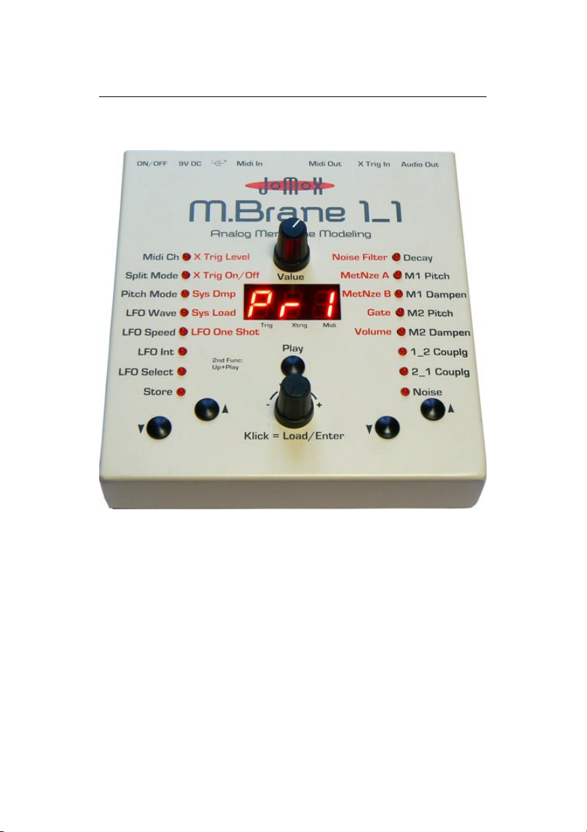
The M.Brane 11 has following connections:
9 V D CO N / O F F
M id i I n M id i O ut
X Tr ig I n Au dio Ou t
1.1. 9V DC
The provided 9V DC wall wart adapter has to be plugged into this
jack. Please don’t use other wall wart adapters. If though, please use
a 9 Volt DC (mAmps don't care) universal power supply with a 2.5
mm plug, plus inner contact, minus outer contact.
1.2. Midi In
Here you can hook up another midi device to control the M.Brane 11
by either a software sequencer, a controller box or any other
hardware device like e.g. a JoMoX XBase09, XBASE999/888. Please
use a cable that is as short as possible.
1.1. Midi Out
Connection of the M.Brane 11 to a midi capable device to receive
midi sys ex dumps or note trigggers from the M.Brane 11. Please use
a standard midi cable which is as short as possible.
1.2. Trigger In
Audio input to trigger the M.Brane 11 by an audio signal or drum
pad. Connect the Trigger In to an appropriate drum pad piezo pick
up or audio source, for instance the output of a mixer or a CD-Player.
Please use a standard 1/4" audio cable.
M.Brane 11 Operating Manual 5
Page 6

Connections
1.3. Audio Out
Outputs the audio signal of the M.Brane 11. The output is mono
unbalanced and has a line level of about 0 dBu. Hook up the Audio
Out to an appropriate audio mixer or amplifier. Please use standard
mono ¼” audio cables.
6 M.Brane 11 Operating Manual
Page 7
Functional Description
2. Functional Description
The M.Brane 11 is a true analog synthesizer optimized for percussion
sounds. The most important parts of the sound are composed by a
membrane-like T-OSC network and noise being mixed together.
Those, who don't want to spend their attention too much with the
technical details of the sound production may jump now to chapter 3.
Sound Parameter.
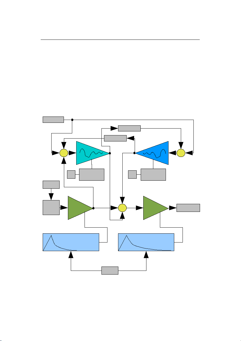
How does it work?
Pic. 1: M.Brane 11 block diagram
M.Brane 11 Operating Manual 7
M1
M2
Final VCA
Trigger
1_2 Couplg
2_1 Couplg
Pitch
Dampen
Pitch
Dampen
Noise VCA
Noise Envelope
Loudness Envelope
++
+
Output
Noise
Decay
LFOLFO
Intensity
6dB Filt
Page 8
Functional Description
The sound production in the M.Brane 11 is made up of 2 T-bridge
oscillators (M1 and M2) that have a different frequency range. M1 is
tuned about an octave higher than M2.
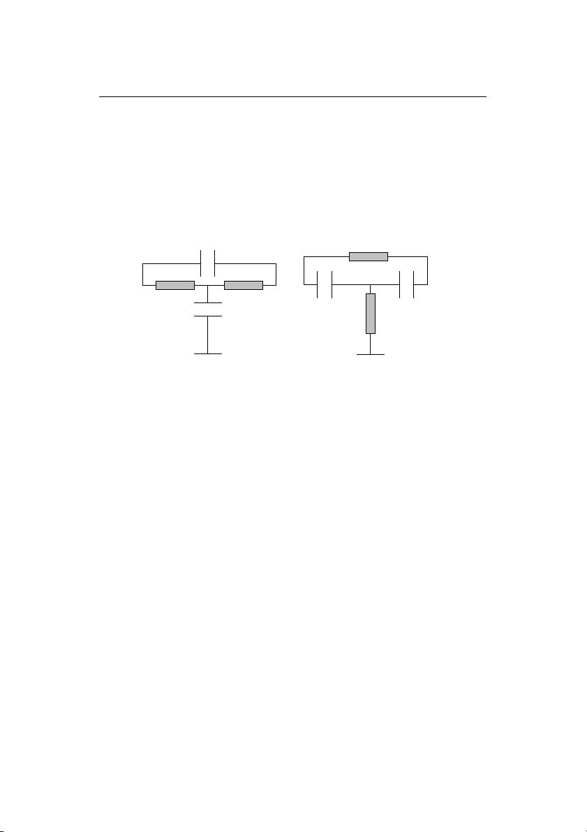
A T-bridge oscillator (T-OSC) is actually something like a band pass
filter which is working close to the resonant frequency. The name
comes from the basic circuitry in which each 2 resistors and 2
capacitors form a network that looks similar to a T:
Pic. 2: T-Bridge Netzwerk, both variants are equivalent (The active
part has been left out).
This kind of sound generators has often been used throughout the
1970/80s in vintage drum machines as the tonal basis for percussion
instruments – as e.g. in the CR-78 or TR-808.
Because the T-bridge becomes an actual sine oscillator at perfect
tuning of its components, you call the deviation of ideal resonance
dampen. In this case, the oscillator decays in form of an attenuated
vibration if it's exited - similar to a single membrane that is hit.
In the M.Brane 11 there are two of such T-OSC. The dampen can be
either negative (as just described) or positive. Then it really becomes
a continuously vibrating oscillator. The more negative the dampen is,
the more the T-OSC becomes a filter with sharp q-factor (quality).
This can be useful at e.g. snare drums or hi hat-ish sounds.
8 M.Brane 11 Operating Manual
R1 R2
C2
C1
R1
C2
R2
C1
≡
Page 9

Functional Description
Looking at the drumskins of an acoustic drum, there are 2
membranes positioned that modulate and interact with each other by
the coupling through pressure waves of the content air. That
produces the typical sound of a drum. By resonance and
counteractive interference of waves new frequency bands and
overtones create.
Similar to that the parameter Coupling works at the M.Brane 11.
Both, in the first place independently vibrating T-OSCs, can attenuate
or gain the vibration of the partner by means of negative or positive
coupling on either ways (1_2 and 2_1). With lightfingered tweaking
you get these interesting membran-like dampened sounds, especially
by cross-wise positive/negative coupling.
The values can sometimes be very close to another. Therefore it is a
great advantage that the M.Brane allows for storing the parameters
(by use of digital potentiometers as R's in Pic.2), because sometimes
tiny value changes can cause great sound changes if the system is
close to a chaotic state.
The M.Brane definetely is something for sound nerds - less for
preset-twiddlers, as the manifold and sensitive modulation settings
want to be explored and played with.
In order to create snaredrum- or cowbell-like sounds, the M.Brane 11
has a noise generator with an own envelope. A part of this signal is
fed into the T-bridge network to exite the "membrane" with the noise
signal itself. Another part of the noise signal ist mixed into the final
VCA (Voltage Controlled Amplifier) which produces the overall volume
envelope of the resulting instrument. The noise can be wether white
noise or metal noise, which is a binary pattern of different metallic
sounding frequency bands.
The length of noise decay and the decay of the resulting tone are
controlled by two different envelopes that are commonly controlled
by the parameter Decay. The noise envelope is always shorter than
the final VCA envelopes. That lets you work out the precise noise
attacks by tweaking the Decay. The T-OSC's mostly have their own
M.Brane 11 Operating Manual 9
Page 10

Functional Description
decay themselves, and they only sometimes need an own (and then
longer) loudness envelope.
The LFO can either modulate a choice of one T-OSC or both. It
always restarts with the note trigger and works like an additional
pitch envelope.
In Split Mode 2 both the T-OSCs or only M2 can be played over the
keyboard, which again makes it a creative thing to play.
2.1. Listening to Preset Sounds
As long none of the 16 leds lights up, the M.Brane 11 is in preset
mode. With the endless value knob you can recall 110 preprogrammed factory sounds.
The display shows up < Pr0 > to < Pr9 > for the E²prom-stored
user presets and < r00 > to < r99 > for the flash memory sounds.
The factory "r" sounds are stored in a flash memory area that can
also be overwritten by the user. We recommend to use the user
presets < Pr0 - Pr9 > for frequent programming jobs and the "r" or
flash memory area for the rarely changed archive material. In the
M.Brane 11 however, the number of guaranteed error-free storage
cycles to flash memory by the manufacturer is nearly unlimited
(>100,000).
With the Play button you can trigger and listen to the sounds.
10 M.Brane 11 Operating Manual
Page 11

Functional Description
2.2. Control of the M.Brane 11 by Midi
2.2.1. Note Trigger
The M.Brane 11 processes midi note commands. Thus, it can be
triggered by any midi sequencer. If the M.Brane 11 receives midi
data on its own channel, a dot under the display lights up. The
settings of the various midi functions please find in the Midi
Implementation at the end of this documentation.
2.2.2. Parameter Control by Midi Controllers
All sound parameters can be controlled by continuous midi controllers
(CC). The controller map can be found in the Midi Implementation at
the end of this operating manual.
2.2.3. SysEx Dump
The memory content of the M.Brane 11 (means the presets) can be
transferred to a midi sequencer or file player by a sysex dump. Only
single presets are sent and received. So you can reorder your presets
and store them back in another order. Thus the sysex transmission
time is way shorter and doesn't make trouble with newer sequencer
systems, which are sometimes less capable of handling continuous
midi data streams.
2.2.3.a) Transmit Dump:
Set the connected midi device to record mode, activate the 2
nd
function and press the down button until "dMP" appears in the
display. Transmission of the sysex dump is triggered by pressing the
click of the value knob. The display reads "rDY".
M.Brane 11 Operating Manual 11
Page 12

Functional Description
2.2.3.b) Receive Dump:
Activate the 2nd function and press the down button until the display
reads " Ld" (load). By clicking on the value knob you set the device
into record mode, which is displayed by a flashing LED display. As
soon as you play back a previously recorded sysex dump, the
M.Brane 11 acknowledges the received preset by displaying "fin". The
data is automatically stored in the actual preset number.
2.3. Control of the M.Brane 11 by X Trig In
The X Trig In is an analog input which lets you trigger the M.Brane
11 by an audio signal, a click track or a drum pad pick up. It works in
parallel to the midi control, so that triggering by midi and by analog
trigger is possible at the same time. Also you can change the sound
parameters by midi controllers during the triggering by Trigger In.
If the Trigger In of the M.Brane 11 receives a signal, the decimal dot
next to the second digit flashes.
2.3.1. Triggering with a drum pad
- Just hook up an appropriate drum pad pickup (for instance a piezo
pickup that is attached to a snare drum) to the X Trig In.
- Press the buttons Up + Play at the same time (upmost LED blinks)
and crank up the trigger level with X TRIG Level until the
M.Brane 11 triggers on a hit. After 60 sec. of no input, the display
jumps back to the preset selection mode.
On a received trigger, a note on is sent via Midi Out so that you can
use the M.Brane 11 as a simple trigger-to-midi converter – however
only trigger, no pitch information. Have fun!
12 M.Brane 11 Operating Manual
Page 13

Functional Description
- Set X Trig On/Off to <on> (default setting), if it wasn't selected
before. Here you can turn off or on the trigger function without
changing the trigger sensivity if needed.
- To transfer the trigger settings into global memory, store the preset
you are in once again like in 4.8 Store described. Then, after next
power-up, the trigger information is available again.
2.3.2. Triggering with an Audio Signal
The M.Brane 11 can be triggered by any audio signal too. The audio
material has to have enough high peaks to trigger the M.Brane 11
properly. The higher and shorter those peaks are, the more precise
the triggering. Maybe you have to provide an own mixer channel for
triggering in your setup and lower the bass EQ in it, although the
direct signaling works perfect in most cases.
Hook up the audio source (DJ mixer, CD player, etc.) to the M.Brane
11 and set the controls as described above at 2.3.1. to obtain the
best result without double triggers or drop outs.
M.Brane 11 Operating Manual 13
Page 14

Sound Parameter
3. Sound Parameter
Choosing with up/down buttons, changing values with the
endless value knob. At the same time you can adjust the value by
the potentiometer above the display to edit wide ranges quicker and
with more feeling. The value has to be picked up with the
potentiometer first to control it then continuously: turn the
potentiometer to about the shown value, and it will lock in and be
able to change the parameter. If the endless encoder is used again,
the potentiometer locking is lost. You can re-lock it of course again.
We recommend to unlock the pot again by pressing once the
up/down buttons (parameter change) or by one or two clicks with the
endless encoder after editings made by the potentiometer. If the
parameter remains on potentiometer input, it may produce some
unwanted slight zipper noise effects by the unavoidable jittering
between two values. This is important especially on recordings.
14 M.Brane 11 Operating Manual
Page 15

Sound Parameter
In the M.Brane 11 there are more than 8 parameters. If you step
beyond “Noise” by pressing the down button, the first LED starts to
blink. Now the the red marked parameters left to the LED column are
active. If you extend “Volume”, you are again in preset selection
mode – no LED lights up.
Opposingly, you start with “Volume” if you go up from preset
selection mode by pressing the up button and ascend to “Noise
Filter”. Now the LED jumps over to “Noise” and goes up to “Decay”
and then only jumps back to preset selection mode.
3.1. Decay < 000-255 >
Controls the decay time (length) of the M.Brane 11. As can be seen
in Pic.1, this value controls either the noise envelope and the final
VCA envelope. The noise envelope is always shorther than the final
VCA envelope in order to adjust the noise attacks precisely, whilst the
decay of T-OSC M1 and M2 are mostly controlled by parameter
Dampen.
3.2. M1 Pitch < 000-255 >
This parameter controls the pitch of the first membrane oscillator M1
(T-OSC). The range is from about 150Hz to 18kHz. The membrane
oscillator M1 is about an octave higher than M2. Please note that the
pitch is also little affected by the settings of M1 Dampen and both
coupling parameters 1_2 Couplg and 2_1 Couplg. Because of the
sensitive analog circuitry, these values interfere each other a little bit
so that re-adjustment of values may be neccessary to achieve a
special sound.
At very high pitches of the wide tuning range, the resolution of the
used digital potentiometers is rather narrow so that small value
changes can cause large frequency shifts.
M.Brane 11 Operating Manual 15
Page 16

Sound Parameter
3.3. M1 Dampen < (-128)-127 >
By the parameter M1 dampen you change the decay of sound, means
the dampen of T-OSC M1. The value has a zero position. If turned
into positive direction, M1 fades longer and becomes a steadily
vibrating oscillator. Although values above about 30 are not very
useful in most cases because the T-OSC starts to distort and turns
more and more into a rectangle, we did not limit the possibility and
think that some of you guys would use it as an effects sounds –
especially with the final VCA envelope controlled by decay.
Values below zero shorten the decay, and the T-OSC M1 becomes
more and more a filter with a high peak resonance or Q (quality).
Please note that the decay and value ranges are not fully
independent from the wide tuning range of the T-OSCs.
3.4. M2 Pitch < 000-255 >
This parameter controls the pitch of the second membrane oscillator
M2 (T-OSC). The range is from about 75Hz to 15kHz. The membrane
oscillator M2 is tuned about an octave deeper than M1. Other than
that, the same qualities yield like in 3.2. M1 Pitch described.
3.5. M2 Dampen < (-128)-127 >
By the parameter M2 Dampen you change the decay of sound,
means the dampen of T-OSC M2. Other than that, the same qualities
yield like in 3.3. M1 Dampen described.
3.6. 1_2 Couplg < (-128)-127 >
This parameter determines the coupling between M1 and M2. The
value can be either positve or negative. This controls at which phase
(+/-) the signal is coupled (added) from M1 into M2. Zero is the
16 M.Brane 11 Operating Manual
Page 17

Sound Parameter
initial setting at which no interference occurs. If both coupling
parameters have the same sign, they gain each other and create a
feedback vibration of both T-OSC. At opposing signs, they attenuate
each other. By playing with these two parameters you can create
those wave interferences and interactions that are characteristic for
membrane-like percussion sounds.
3.7. 2_1 Couplg < (-128)-127 >
This parameter determines the coupling between M2 and M1. The
value can be either positve or negative. This controls at which phase
(+/-) the signal is coupled (added) from M2 into M1. Zero is the
initial setting at which no interference occurs. Other than that, the
same qualities yield like in 3.6. 1_2 Couplg described.
3.8. Noise < 000-255 >
The noise signal creates the snare drum noise or metallic attacks.
The parameter Noise controls the intensity of this signal. As can be
seen in Pic.1, the noise signal is processed by a noise envelope and is
then mixed into the T-OSC network and a small portion into the final
VCA.
In the T-OSC network, the noise mixes up with the hit (trigger pulse)
and the T-OSC sounds in a similar way like in a real snare drum and
reaches a fairly homogeneous sound. If Noise is too much cranked
up (>180) it may lead to internal distortions that might be desired
though.
The noise may be either random white noise (MetNze A = <000>) or
metallic noise made up by thousands of combinations between
MetNze A and B.
M.Brane 11 Operating Manual 17
Page 18

Sound Parameter
3.9. Noise Filter < 000-255 >
Behind the noise level control there is a simple 6 dB/octave low pass
filter which can make the noise a bit more dull. A strong filtering of
noise with a 6 dB/octave filter is also known as “pink noise“. The
noise looses its sharpness if you crank up this value. At <000> the
filter is opened and lets all high frequency parts pass through. The
function is therefore in opposite to an EQ, because the initial state
<000> means: no affection of the noise signal.
3.10. MetNze A < 000-255 >
Changes the noise of the noise generator to a metallic noise. At a
value of <000> the noise is a random white noise. On values above
that a complex signal is made from high pitch digital multi tones
according to the bit pattern of the value. Each unique single
frequency pattern is corresponding to a pair of value numbers of
MetNze A and B. If you turn the parameter up, it does not result in a
continuous signal change over the value range, but instead the signal
patterns jump with each number. However, almost every time they
return with very interesting frequency mix patterns similar to a
caleidoscope. Try and check it out.
3.11. MetNze B < 000-255 >
See 3.10 MetzNze A. Only MetNze A can switch metallic noise to
random white noise if set to <000>.
3.12. Gate < A00-A63 / b00-b63 / C00-C63 / d00-d63 >
The gate time for the trigger of the analog T-OSC circuitry can be
changed within 1ms to 5 ms. This parameter significantly affects the
sound of the attack.
18 M.Brane 11 Operating Manual
Page 19

Sound Parameter
If the value is cranked up above 63, two 1 ms impulses with a delay
of about 8ms are created, of which the length of each impulse can be
varied again up to 5ms. Thus, you can produce flam- or clap-like
attacks. Purposefully the delays between the multi trigger pulses are
never 100% exact and jitter a little what makes them sound a bit
more natural. Up to 4 multi triggers are possible.
<A00-A63> 1 trigger impulse
<b00-b63> 2 trigger impulses
<C00-C63> 3 trigger impulses
<d00-d63> 4 trigger impulses
3.13. Volume < 000-255 >
Controls the main level of the M.Brane 11. The velocity of incoming
midi notes is only processed up to this main volume. For best
sounding results keep this value at <255>.
3.14. Endless Value Knob
The endless value knob is used for selection of a preset or
adjustment of parameter in edit mode. As soon a value is changed, it
is indicated by a lighting red dot right down in the display (Edit On).
By clicking on the value knob (pressing it) during any edit modes the
preset can be reloaded from memory and the Edit On display
disappears. The click function also serves as an enter key for some
functions like storing of presets and sysex dump.
3.15. Play Button
Manual triggering of sound. Selection of 2nd function by pressing play
and up button simultaneously. See also 4.9. 2nd function.
M.Brane 11 Operating Manual 19
A00-A63
1-5ms
~8ms
b00-b63 C00-C63
1-5ms
Page 20

Master Parameter
4. Master Parameter
Selection with up/down buttons, changing values with the
endless value knob. If after 60 seconds no further input is made
with the value knob, the unit switches automatically back to sound
parameter or preset selection.
20 M.Brane 11 Operating Manual
Page 21

Master Parameter
4.1. Midi Ch(annel) < 001 - 016 >
Defines the midi channel on which the M.Brane 11 sends and
receives midi. Following midi data is received: note on/off, -number,
program change, CC controller, sysex data. Transmitted data: note
on/off, -number, program change, sysex data.
4.2. Split Mode < SM1 / SM2 >
<SM1> The percussion instrument is only played by standard note
D1 (GM Snare Drum) with the internally stored pitch.
<SM2> The percussion instrument is played over the whole
keyboard, varying the pitch depending on the key pressed.
Please note the following:
Because of the used analog circuitry in combination with the
implemented digital potentiometers and the very wide but in discrete
steps adjustable tuning range, it is impossible to play the T-OSC in
musical semitones. All parameters as Pitch, Dampen and Coupling do
interfere with each other affecting the tuning, and the ranges are
way to wide. So we easily assign each note to a tune value of M1 and
M2 which makes it much more intuitive in the end. And because the
ranges can be very different, it may also be that tune ranges skip
over the keyboard when they reach their limit or sound completely
different because the dampen shifts in the high pitch area.
Just think and make use of it in a creative way. One can greatly work
with it if you get rid of thinking about semitones and only
concentrate on the sound or the pitch of the instrument.
4.3. Pitch Mode < Lin / M 2 >
<Lin> The pitch (the T-OSC frequency) of M1 and M2 is controlled
as a linear frequency over the keyboard in Split Mode 2 (see above).
<M 2> The pitch is only directed to M2, the lower of both T-OSC,
whilst M1 remains on the internal pitch. Very interesting e.g. for
Bongos or Congas.
M.Brane 11 Operating Manual 21
Page 22

Master Parameter
4.4. LFO Wave < SuP / Sdo / Sin / Si- / tri / tr- / rCt / rC- >
With the LFO (Low Frequency Oscillator) you can produce periodic
pitch changes (vibrato) by modulation.
The polarity of waveform is of importance as the LFO always restarts
on a note trigger. Therefore the LFO works like a pitch envelope that
is triggered by a note event.
The wave parameter determines the LFO wave form:
<SuP> Saw up / saw tooth with ascending ramp /|
<Sdo> Saw down / saw tooth with decending ramp |\
<Sin> Sine with ascending wave form
<Si-> Sine with descending wave form
<tri> Triangular wave form with ascending and descending ramp /\
<tr-> Triangular wave form with descending and ascending ramp \/
<rCt> Rectangular, jump from maximum to minimum value
<rC-> Rectangular, jump from minimum to maximum value
4.5. LFO Speed < off / 040-290 >
Speed of LFO modulation. This value displays the speed of the LFO
directly in BPM (Beats Per Minute). Each waveform runs through once
in a quarter of the selected tempo beat.
The lowest value <oFF> shuts down the LFO. Because it is rather
unavoidable that the LFO affects the software driven metal noise a
little in sound by the internal interrupts, you can turn it off if desired.
4.6. LFO Int(ensity) < 000-255 >
Controls the intensity of the LFO. A value of 0 shuts the LFO off.
22 M.Brane 11 Operating Manual
Page 23

Master Parameter
4.7. LFO Select < oFF / M1_ / M_2 / M12 >
<oFF> The LFO is shut off.
<M1_> The LFO modulates only T-OSC M1.
<M_2> The LFO modulates only T-OSC M2.
<M12> The LFO modulates both T-OSC M1 and M2.
4.8. Store
I you want to store a sound preset, press the up button once to enter
Store. The display blinks and shows the current preset number. Now
select the wanted preset number you want to store the sound to by
the endless value knob if it is different to the current one.
Clicking on the value knob performs the storage process. This
automatically contains a copy function, because if you store a nonedited preset to another location than the actual preset, the M.Brane
11 stores an identical copy of that preset to the other location.
4.9. 2nd Function
Select by pressing UP and PLAY button at the same time
(upmost LED flashes). If not an input is made by the value
knob or the up/down buttons within 60 seconds, the device
returns to sound parameter or preset selection.
4.9.1. X Trig Level 2nd Funct < 000 - 255 >
Controls the sensivity of the Trigger In. The higher this value is, the
more sensitive is the input and so it can be well adapted to any kind
of the used audio or trigger source. The value is stored globally if a
sound preset is stored (see 4.8. Store).
M.Brane 11 Operating Manual 23
Page 24

Master Parameter
4.9.2. X Trig On/Off 2nd Funct < oFF/ _on >
The external trigger can be switched off and on. The sensivity of X
Trig Level is unaffected by this setting.
4.9.3. Sys Dmp 2nd Funct < dMP / rdY >
A click on the endless value knob sends out the sysex dump. See also
2.2.3.a) Transmit dump.
4.9.4. Sys Load 2nd Funct < _Ld / fin >
A click on the endless value knob enables M.Brane 11 sysex reception
mode. See also 2.2.3.a) Receive dump.
4.9.5. LFO One Shot 2nd Funct < oFF/ onE >
<oFF> The LFO runs continuously and modulates the pitch of both
the T-OSC M1 and/or M2.
<onE> The LFO runs only through one wave form and can therefore
be used as an additional effects envelope.
24 M.Brane 11 Operating Manual
Page 25

M.Brane 11 Midi Implementation
5. M.Brane 11 Midi Implementation
5.1. Sound Parameter CC
In the M.Brane 11, the fine resolution controllers such as Tune and Dampen
can be sent with 2 MSB/LSB controllers in order to have the full 8 bit
resolution. Most state-of-the-art sequencer programs are able to do this, you
only have to define the controllers as 14 bit CCs with MSB and LSB and edit
the corresponding values.
The other controllers use one step of 7 bit CC resolution for 2 steps 8 bit
internal resolution. However, with these parameters the controlling range is
absolutely satisfying.
Parameter Controller No. Value Range Internal Resolution
Decay 110 0..127 256
M1 Pitch MSB 90 0..1
M1 Pitch LSB 91 0..127 256
M1 Dampen MSB 92 0..1
M1 Dampen LSB 93 0..127 256
M2 Pitch MSB 94 0..1
M2 Pitch LSB 95 0..127 256
M2 Dampen MSB 96 0..1
M2 Dampen LSB 97 0..127 256
M1_2 Couplg MSB 100 0..1
M1_2 Couplg LSB 101 0..127 256
M2_1 Couplg MSB 102 0..1
M2_1 Couplg LSB 103 0..127 256
Noise 109 0..127 256
Noise Filter 112 0..127 256
Metal Noise A MSB 106 0..1
Metal Noise A LSB 107 0..127 256
Metal Noise B MSB 115 0..1
Metal Noise B LSB 116 0..127 256
Gate 114 0..127 256
Volume 117 0..127 256
LFO Wave 119 0..7 Sup/Sdo/Sin/Si-/tri/tri-/rCt/rCLFO Select 120 0/32/64/96 Off/M1/M2/M12
LFO One Shot 123 0/64 Off/On
LFO Intensity 121 0..127 256
LFO Speed 122 0..127 256
M.Brane 11 Operating Manual 25
Page 26

M.Brane 11 Midi Implementation
For limited controllability by the Jomox XBASE 09/888/999 in the
snare drum department these CCs are intended:
Parameter Controller No. Value Range XBase Parameter
M1 Pitch LSB 108 0..127 Snare Tune
Noise 109 0..127 Snare Snappy
Decay 110 0..127 Snare Decay
M2 Pitch LSB 111 0..127 Snare Detune
Noise Filter 112 0..127 Snare Noise Tune
5.2. Soft Calibration
Since there are unavoidable analog tolerances of the T-Bridge
oscillators and the partly very sensitive effects on the sounds we
have implemented calibration values for the parameters pitch and
dampen in order to keep the factory spreadings at a reasonable level.
These values keep permanently stored and can only remotely be
changed by CC controllers. After adjustment, they have to be stored
so that they are active on next turning on.
A CC value of 64 corresponds to 0% deviation. Smaller values
decrease, higher values increase the tuning and will be automatically
added or deducted with every sound played. We recommend not to
overwrite the factory settings, but a damadge to the unit is not to be
expected.
Parameter Controller No. Value Range Initial Value
M1 Pitch Cal 98 0..127 64
M1 Dampen Cal 99 0..127 64
M2 Pitch Cal 104 0..127 64
M2 Dampen Cal 105 0..127 64
Store Preset 62 0/64 Store Preset
26 M.Brane 11 Operating Manual
Page 27

M.Brane 11 Midi Implementation
5.3. Note Commands
Instrument Split Mode 1 Split Mode 2
Note Number Note Number
M.Brane 11 D1 (38) C1..C6
5.4. System Exclusive Data
Only actual chosen preset hex dumps are sent and received with Sys Ex data
because the sound control is normally done with midi cc controllers.
The System Exclusive control command line looks as follows:
$F0(SysEx begin), $31(JoMoX- manufact. code), $7F(Command Sys Ex
dump), $5a(Product code), $XX(Preset No.),XX(Data0),XX(Data1),..., $F7(End
of SysEx)
16 bytes (0..255) of data per preset are transmitted. They are split into MSB
(bit 7) in Data0 and LSB 0..127 in Data1. The MSB (Most significant bit) is
coded in Data0 = 1 or = 0, depending if bit 7 of the actual byte was set or
cleared.
The numbers and digits of Sys Ex sequences are shown, as always, in
hexadecimal numbers.
And finally...
Service, tips and tricks:
JoMoX GmbH
Körtestr. 10
10967 Berlin / Germany
http://www.jomox.com
email mail@jomox.de
We wish you lots of fun on creative usage of our products!
© 2010
Jürgen Michaelis
M.Brane 11 Operating Manual 27
 Loading...