

Page 1
Water
FOGHET
stove
WOOD version
Curved or straight front
INSTALLATION, USE
AND MAINTENANCE MANUAL
To be carefully kept by the owner
FOGHET
With curved front
FOGHET
With straight front
Page 2
Read this card carefully and follow the instructions for quick
installation and correct use of the fireplace.
Before starting installation, read the card carefully and follow
the instructions; failure to do so could invalidate the warranty
and compromise fireplace performance and safety.
This installation card is an integral and essential part of the
product and must be given to the user.
It must kept in safe place and carefully consulted, as it provides
important information on safety during the installation, use and
maintenance stages.
Incorrect installation can cause damage and injury, for which
the manufacturer cannot not be held liable.
The unit must only be used for its intended purpose. Any other
use is deemed improper and therefore dangerous.
The manufacturer declines any contractual or non-contractual
liability for damage caused by errors in installation or use,
failure to follow the instructions contained in this card, or
installation in places or rooms unsuitable for the
characteristics of the product.
All rights to reproduction of this card belong to JOLLY-MEC
CAMINETTI S.p.A.
The descriptions and illustrations provided in the following
publication are not binding.
JOLLY-MEC CAMINETTI S.p.A. reserves the right to make any
changes it deems necessary at any time.
This card cannot be given to third parties to read without the
written permission of JOLLY-MEC CAMINETTI S.p.A.
The technical instructions for assembly contained in this
handbook are considered basic requirements. The regulations
in some countries may be more restrictive; in this case carefully
comply with the regulations in the country of installation.
Page 3

CONTENTS
3
USE AND MAINTENANCE INSTRUCTIONS FOR THE USER
1.1 Introduction to the Foghet water stove............................................................................................................................................................................................................................................................4
1.2 Technical specifications
..................................................................................................................................................................................................................................................................................................5
1.3 Dimensions and components
....................................................................................................................................................................................................................................................................................6
1.4 Example of combined Foghet stove with curved front installed and covered
..................................................................................................................................................7
1.5 Burner and pellet hopper components
..........................................................................................................................................................................................................................................................8
1.6 New-generation simplified electronic controller
..................................................................................................................................................................................................................................9
1.6. Description and use of simplified electronic controller for water heating
........................................................................................................................................9
1.6.2 Setting the display language
..............................................................................................................................................................................................................................................................10
1.6.3 Ignition in pellet burning mode, controller
..........................................................................................................................................................................................................................10
1.6.4 Quick menu
............................................................................................................................................................................................................................................................................................................12
1.6.5 Power output setting for pellet burning mode
..............................................................................................................................................................................................................13
1.6.6 Room temperature setting for pellet burning mode
................................................................................................................................................................................................13
1.6.7 How to silence an alarm
........................................................................................................................................................................................................................................................................14
1.6.8 Summer operating mode
......................................................................................................................................................................................................................................................................14
1.6.9 Electronic component tests
................................................................................................................................................................................................................................................................14
1.6.10 Solving problems related to combustion
..............................................................................................................................................................................................................................14
1.6.11 Use of the programmable thermostat
......................................................................................................................................................................................................................................15
1.6.12 Ignition in wood burning mode
........................................................................................................................................................................................................................................................17
1.7 How to optimise combustion and use the damper
........................................................................................................................................................................................................................18
1.8 Operating tips and warnings
....................................................................................................................................................................................................................................................................................19
1.9 Cleaning the stove
..............................................................................................................................................................................................................................................................................................................20
1.10 Components that can be removed for cleaning the stove
..................................................................................................................................................................................................21
1.11 Plumbing kit components requiring routine maintenance
....................................................................................................................................................................................................22
1.12 Troubleshooting
........................................................................................................................................................................................................................................................................................................................23
1.13 Optionals
........................................................................................................................................................................................................................................................................................................................................26
1.14 Auxiliary large capacity pellet hoppers
........................................................................................................................................................................................................................................................27
1.15 Pellet quality
................................................................................................................................................................................................................................................................................................................................28
1.16 Use and conservation of the installation and maintenance manual
........................................................................................................................................................................29
1.17 Warranty
..........................................................................................................................................................................................................................................................................................................................................30
1.18 Assistance Service
..............................................................................................................................................................................................................................................................................................................30
ASSEMBLY INSTRUCTIONS FOR THE INSTALLER
2.1 Flue ................................................................................................................................................................................................................................................................................................................................................31
2.2 Prearrangement for connections and air inlets of the stove positioned in a corner
............................................................................................................................32
2.3 Prearrangement for electrical connections and air inlets with wall installation
..........................................................................................................................................33
2.4 Adjusting the feet
..................................................................................................................................................................................................................................................................................................................34
2.5 Damper and friction unit assembly
..................................................................................................................................................................................................................................................................34
2.6 Caldo Control
............................................................................................................................................................................................................................................................................................................................35
2.7 Standard plumbing kit
......................................................................................................................................................................................................................................................................................................36
2.7.1 With production of domestic hot water in a sealed system
..........................................................................................................................................................................36
2.7.2 Without production of domestic hot water in a sealed system
..................................................................................................................................................................37
2.8 Non-standard plumbing kit
........................................................................................................................................................................................................................................................................................38
2.8.1 With production of domestic hot water in an open-vented system,
connected to mains water supply for domestic hot water and boiler cooling
..........................................................................................................................38
2.8.2 Without production of domestic hot water in an open-vented system,
connected to mains water supply for boiler cooling
..............................................................................................................................................................................................39
2.9 Installation examples
........................................................................................................................................................................................................................................................................................................40
2.9.1 Installation in autonomous sealed system with production of domestic hot water
..........................................................................................................40
2.9.2 In a sealed system with production of domestic hot water, in parallel with wall-mounted boiler
..................................................................40
2.9.3 In a sealed system without production of domestic hot water,
connected in parallel with a wall-mounted boiler for domestic hot water production
..................................................................................................41
2.9.4 In an autonomous sealed system with thermal cell and solar panels for radiator heating and domestic hot water
..............42
2.9.5 In an autonomous sealed system with thermal cell and solar panels for production
of domestic hot water and radiator and underfloor heating
........................................................................................................................................................................43
2.9.6 In a sealed system, without production of domestic hot water, connected in parallel to wall-mounted boiler
with domestic hot water production and solar panels with thermo boiler, hot water storage cistern
......................................................43
2.10 Electrical wiring diagram for simplified controller
............................................................................................................................................................................................................................44
2.11 Purchased product data
................................................................................................................................................................................................................................................................................................45
Page 4

1.1 Introduction to the FOGHET water stove
4
The ”FOGHET” with curved or straight front is a water heating
machine type approved and tested according to European
standards EN13229, EN14785, EN303/5 and German
standards DIN18894, DIN18891, DIN18892 burning firewood
or firewood and pellets (ALTERNATIVE AND RENEWABLE
ENERGIES).
Designed to meet today’s market requirements of: energy
saving, comfort and safeguarding the environment, it is the
result of Jolly-Mec’s 30 years’ experience.
Foghet is a monobloc consisting of a double-wall heat
exchanger in special steel whose particular construction allows
maximum exploitation of the combustion heat, obtaining high
efficiencies of up to 92.74%, making it one of the best in the
category for efficiency and emissions.
The Foghet with curved front can be clad as a fireplace or as a
stove (“FOGO” model); with straight front as a fireplace or stove
(“FOGHEA” model).
The Foghet with curved front has an electronic controller
(available in two versions, standard or simplified) that manages
the stove when operating on wood or pellets. In both versions it
has a programmable thermostat for automatic lighting and
shutdown. With the new-generation simplified electronic
controller version, when programmed, if the wood finishes and
heating is required the boiler temperature probe makes the
stove automatically switch from wood to pellet mode with
automatic igniting of the pellets, maintaining the set
temperature. The simplified controller warns when the pellets
are finished with a beep and in addition makes it possible to
manage an auxiliary pellet hopper or boiler connected in
parallel, a hot water storage cistern (thermoboiler) or a thermal
cell and the circulating pump of a central heating system. With
the simplified controller it is also possible to run a check-up on
the various components even with the fireplace out.
The Foghet with straight front is supplied with a simplified
controller only.
When used with wood, it functions as a normal stove, but offers
the advantages of controlled combustion thanks to the
Jolly-Mec patented Caldo Control, which optimises combustion
according to the water temperature.
Wood-burning Foghet, with the specific pellet burner JOLLY
ME-04-F fitted, becomes a ”continuous fire” heating machine,
exactly like a boiler. The pellet hopper has a capacity of
approximately 46 kg, however, to obtain a longer burn time it
can be coupled to a second and larger hopper, even located in
another room.
Operation can be quickly switched from wood to pellet mode or
vice versa: by shifting the grille positioned over the burn pot and
selecting the type of feed. In pellet mode, heating power is
managed by means of the electronic controller provided: from
8,000 kcal/h on minimum up to 20,000 kcal/h on maximum.
The stove can be purchased in the wood version and the burner
can be fitted at a later stage, since the stove is already arranged
for it.
It has a large ceramic glass door and for the wood-pellet version
with curved front a removable second inner door with glass is
available, for those who want it to work as a boiler, which
simplifies cleaning, keeping the glass of the outer door always
clean, while reducing the temperature of the front. To use it as a
fireplace the second door removes easily and can be placed in
the special holder (optional)
The water-heating Foghet can also autonomously heat an entire
building with a floor area of up to 170m
2
(with radiators,
underfloor heating, storage cistern, etc.) and produce domestic
hot water. It is supplied as standard with a plumbing kit in a
sealed system, already fitted and tested, with or without
domestic hot water production and a cooler that monitors and
governs the temperature of the water in the event of a power
failure. On request, non-standard, Foghet can also be supplied
with a plumbing kit for open-vented operation, with or without
domestic hot water production.
Page 5

1.2 Technical specifications
5
Recommended fuels:
WOOD: dry beech, hornbeam, oak, locust (acacia)
PELLETS: See pellet characteristics given in chap. 1.16.
All testing, inspections and preparation of the Foghet were
carried out using the recommended pellets.
JOLLY-MEC CAMINETTI
S.p.A.declines any liability for
malfunctions, faults or problems due to the use of nonrecommended pellets, since the combustion parameters vary
from pellet to pellet (they can even vary by approx. 30%).
For optimum operation, combustion must be adjusted using the
pellet feed control on the burner (see chap. 1.8).
Approval EN 13229 EN 14785
353 Burned power (by pellet) 25 kW
366 Thermal rated output (by pellet) 23,2 kW
361 Medium power (by pellet) 15,1 kW
362 Minimum power (by pellet) 9,3 kW
354 Economy power (by pellet) 0,5 kW
302 Consumption at max power (by pellet) 4,7 Kg/h
303 Consumption at med. power (by pellet) 3 Kg/h
304 Consumption at min. power (by pellet) 1,9 Kg/h
305 Consumption in economy power (by pellet) 0,1 Kg/h
357 Max power give to the environment (by pellet) 4 kW
053 Efficiency (by pellet) 92,74 %
352 Burned power (by wood) 27,8 kW
301 Consumption at max power 6,5 Kg/h
356 Max power give to the environment (by wood) 4 kW
052 Efficiency (by wood) 83,49 %
455 Max. heated area depending the kind of house 130-170-270 m
2
451 Surface exchange 1,7 m
2
601 Nominal voltage/frequency 230/50 V/Hz
602 Electrilcal absorption (combined) min-max 360 / 220 W
251 Boiler weight 150 Kg
401 Standars tank capacity 46 l
402 Optional tank capacity 100-400-700 l
702 Min. draft 12 Pa
653 Smoke exhaust Ø 150 mm
551 Sanitary water capacity ΔT 40°C 7 l/min
102 Max T smoke (by wood) 250 °C
103 Max T smoke (by pellet) 193 °C
105 Med T smoke (by wood) 196 °C
106 Med T smoke (by pellet) 145 °C
002 CO (13% O2) (wood) 0,13 %
003 CO (13% O2) (pellet) 0,0048 %
005 CO2 (wood) 9,61 %
006 CO2 (pellet) 11,1 %
202 Smoke volume (by wood) 26,3 g/s
203 Smoke volume (by pellet) 14,08 g/s
008 Dust (pellet) 0 0
007 Dust (wood) 0 0
Code Description Value Unit
Page 6
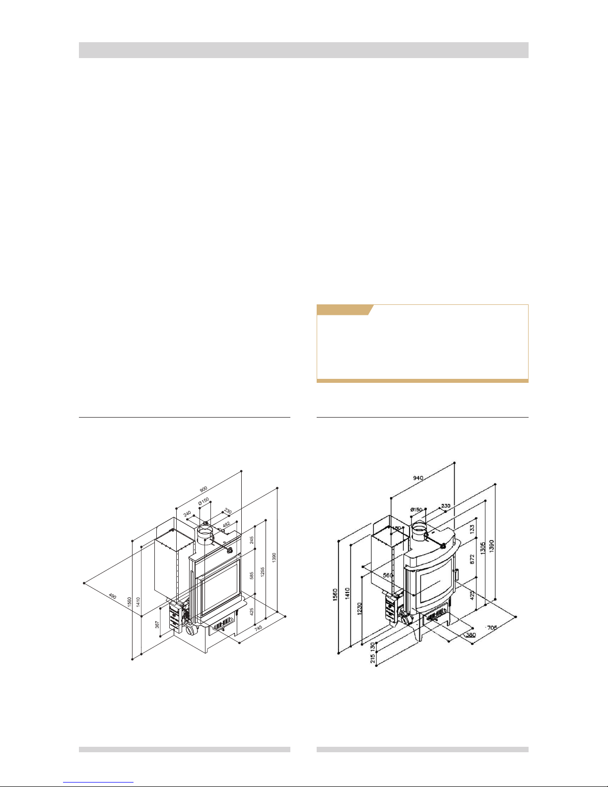
1.3 Dimensions and parts
6
The stove is supplied with a JOLLY ME04 F burner and preassembled and tested pellet hopper, in two wooden crates on pallets, packed
with a cellophane hood, polystyrene and with the following parts:
• Assembly, use and maintenance manual
• Boiler body complete with tested hydraulic kit
• Standard pellet hopper with capacity of approx. 46 kg
• JOLLY ME04 F pellet burner
• Control panel with STANDARD electronic controller or control panel with SIMPLIFIED electronic controller
• Ø 80 mm flexible pipe (not extensible) for burner fan suction inlet
• Ø 80 mm flexible pipe 100 cm long (extensible) for primary combustion air suction from outside (CALDO CONTROL)
• Wood guard (on curved front model only)
• 2 cast-iron grilles for wood burning
• Wrench for burn pot locking screw
• Room temperature probe (with SIMPLIFIED electronic controller only)
• Room temperature probe (with STANDARD electronic controller only)
Cleaning tools supplied (see chap. 1.10)
• Burn pot cleaning tool
• Poker
• Shovel
• Flue brush
• Cleaning brush
OPTIONALS
OPTIONAL SET for curved front models
• Holder f
or accessories and removable inner door
• Removable door
• Spring
• Foghet with straight front • Foghet with curved front
Page 7
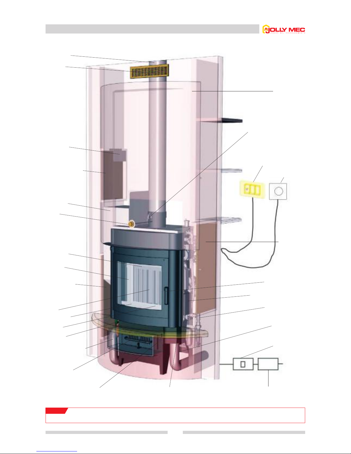
1.4 Example of combined Foghet stove
7
Fume exhaust
Hood front
circulation grille
40x10 cm upper
edge 10 cm from
ceiling
Control panel
Pellet loading door
50X35 cm min. lower
edge 141 cm off
ground MANDATORY
Pellet hopper
Damper
control
Smoke baffle
Removable door
(optional)
Burner inspection
door 80X35 cm
min.lower edge
15 cm off ground
MANDATORY
Boiler
Wood stopper
Burn pot
Burner
JOLLY ME04
Pellet burner fan suction
ducting
Ash pan
with adjustable grille,
for firewood
Air adjustment
caldo control (for
firewood)
Caldo control Electrical power supply
220V-50Hz
Suction
ducting
caldo control
Omnipolar
switch
Plumbing kit
Electronic control unit
Door handle
Lifting hook
Hood
Room temperature
probe for simplified
controller (stand out
2 mm from wall
edge)
room thermostat
(for standard controller)
Inspection door for
controller, caldo
control and
plumbing kit
80x35 cm min.
lower edge 50 cm
off ground
MANDATORY
NOTE!
To allow boiler expansion the cladding must always be separated from the steel fireplace by 2 to 3 mm.
With curved front installed and clad
Page 8
Foghet water fireplace combined wood-pellet version with JOLLY ME 04 F burner 11
1.6 STANDARD electronic control panel
1.6.1 Description of STANDARD electronic control panel
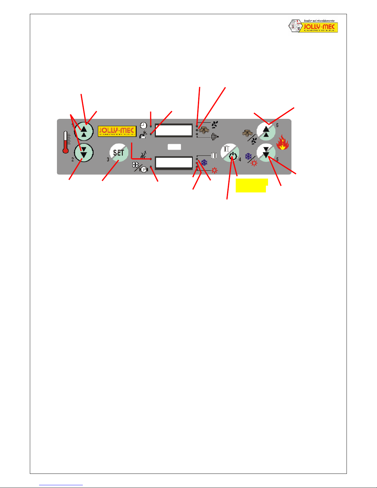
the various led indicate how it is working
CHECK IF THE HOPPER NEEDS CLEANING EVERY DAY
N.B. If the fire goes out, it is not possible to re-light it until it has cooled down, wait for 10 minutes. Repeat the ignition
sequence.
TEXTS THAT APPEAR ON THE DISPLAY
LOAD WOOD: automatic charging of the pellet in the burner hopper for ignition
AIR INTAKE FAN : phase in which the electrical element is heated to light the pellet
FIRE ON: pellet ignition phase and stabilising of the flame, wait for 5-10 minutes
P01,P02,P03: fire output (varies the potential from 1 to 3)
BRAC: phase in which the appliance is kept alight by the embers : load a minimum amount of pellet
ECO: .the temperature of the water in boiler has reached the set threshold (detected by the water temperature
probe) and the fire output goes to economy mode
LE: burning wood
FROM 30° TO 269°: Flue gas temperature
PUL FIRE: automatic cleaning of the pellet burner hopper
SET: press the SET key for 1", the led will flash and you can select from the various functions
OFF: fire is out or is going out
ALAR NO FIRE: the flue gas temperature during ignition is too low, the fire goes out
ALAR NO WOOD: no pellets or pellets not loaded in the hopper
ALAR SOUND FUMI : the flue gas temperature sensor is faulty, the fire goes out
T OFF: he room temperature has reached the set threshold on the room thermostat
DA 0.0b A 4.0b: Water pressure in boiler
FROM 10° TO 100°: Water temperature in boiler
ALAR PRES: the pressure inside the boiler is too high: use the pressure regulator on the delivery tap or plant drain tap
to adjust the pressure to 1.5-1.8 Bar (when hot) or 1-1.2 Bar (when cold)
TO You have accessed the control panel programs To exit press key 4 for 1 sec.
ALAR SCAR FUMI: The pressure switch has cut in due to a poor draught (red indicator light on the burner ON)or the safety
thermostat that stops the boiler has cut in to prevent the smoke blowing back. Check the position of the
basket and clean it. Contact the assistance service if the problem persists.
Flue Gas
Temperature display
Increase room temperature
(first press SET for 1 sec.)
Pellet mode led
Wood mode led
Select wood / pellet (first
press SET for 1 second)
Lower boiler
water temperature
(press SET for 1
second first)
Increase
power
Combustion
fan led
Select functions
and programmes
Winter Led
Summer Led
Hopper
cleaning
led
Manual hopper cleaning
(first press SET for 1 second)
ON/OFF (press
for 4 seconds)
Select summer/winter
(first press SET for 1 second)
Decrease in
power
Time-controlled
Automatic
i
g
nition led
Led
pump
Manual screw
feeder refilling
(press together)
displa
y
displa
y
Page 9
12 Foghet water fireplace combined wood-pellet version with JOLLY ME 04 F burner
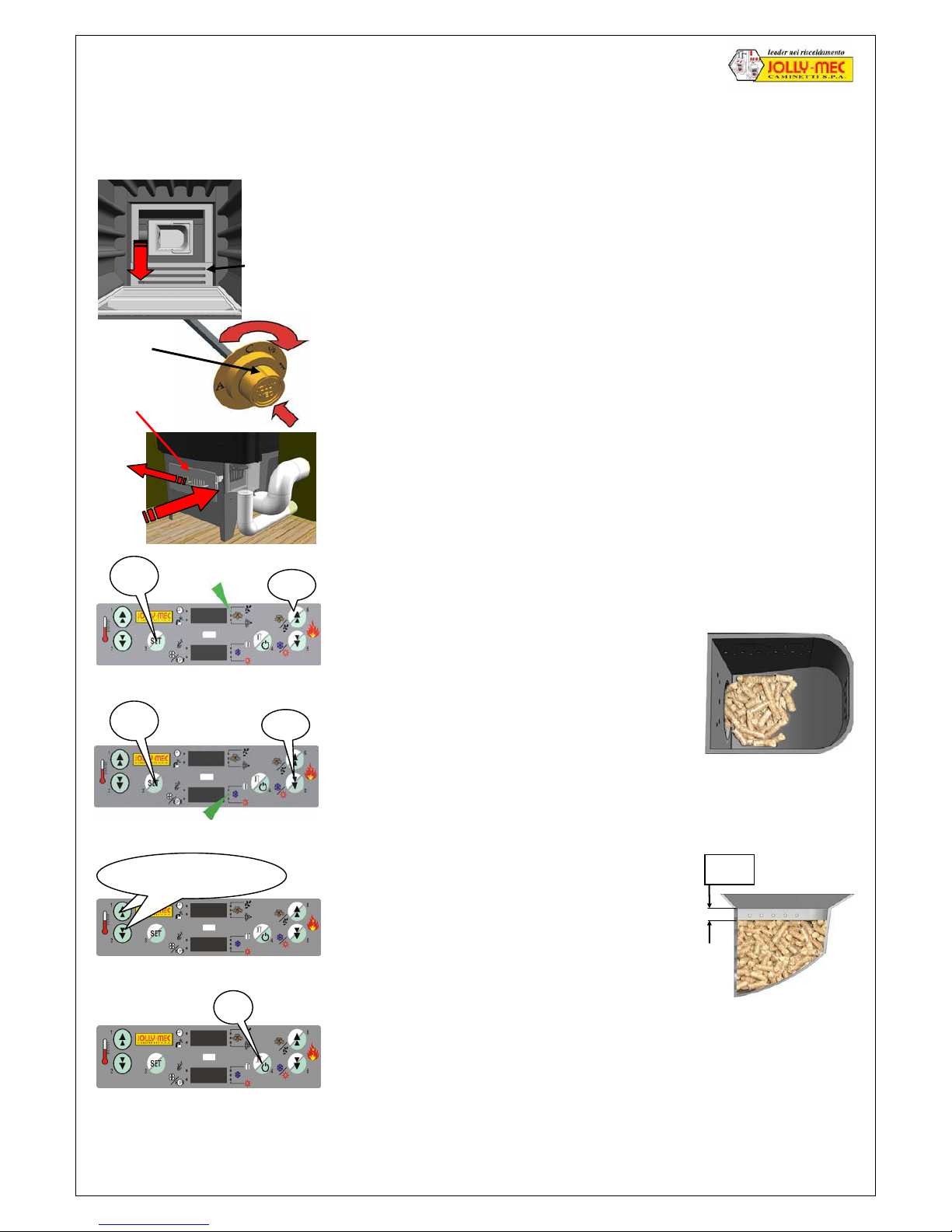
1.6.2 Pellet Ignition , STANDARD control panel
Before igniting the pellet fire it is necessary to complete some preliminary operations :
1. Move the cast iron bottomgrate located above the pellet burner to uncover it
2. Clean the hearth, the burner hopper and empty the ashpan
3. Manually close the flue gas damper by rotating the knob until the notch
indicates position C and block it by pressing the knob until the fastener
screws click into place.
4. Check that the ashpan is correctly closed
5. Close the bottomgrate on top of the ashpan
6. Close the caldo control by pressing the lever as far as possible
7. Check that the control panel is set to pellet mode or the appliance will not
ignite (the relative led must be on). See green arrow.
If the control panel is in wood mode (the relative led is on) switch it to pellet
mode. Press the SET key for 1 second and whilst the led flashes press key 6
for 1 second (the pellet mode led will come on)
8. Check that the control panel is set to winter mode or the appliance will not
ignite (the relative led must be on). See green arrow
If the control panel is in summer mode (the relative led is on) switch it to
winter mode. Press the SET key for 1 second and whilst the led flashes
press key 5 for 1 second (the winter mode led will come on)
9. Manual loading before ignition must be done only
when igniting for the first time and when the hopper
is clean (do not exceed the quantity shown in fig.1)
At all other times MANUAL LOADING MUST NOT
BE DONE because it is done automatically.
When igniting for the first time and during the
programmed ignitions with the chronothermostat, it
is ADVISABLE to open the smoke screen 45° (1/2)
OK FOR THE IGNITION OF THE HEARTH
Never ignite if there is a larger quantity of pellets
10. By pushing the button for ignition, the control panel
AUTOMATICALLY loads the amount of pellets up
to 2 cm from the edge of the hopper; then the
electric resistance starts the ignition phase of the
pellets. If for any reason the level of pellets is
higher, when the resistance starts ignition, remove
the excess pellets because this could cause a
violent ignition.
Before igniting for the second time, the level of
pellets must absolutely be as shown in fig. 1
OK FOR THE IGNITION OF THE RESISTANCE
Notch
Press simultaneously
4”
1"
”
Cast iron
bottomgrates
Grate
Caldo
Control
Ashpan
1"
”
Fig. 1
Fig. 2
2 cm
Page 10

Foghet water fireplace combined wood-pellet version with JOLLY ME 04 F burner 13
The electronic control panel now automatically controls the entire ignition phase in the following order :
1. LOAD PELLET up to 2 cm from the top of the hopper, this lasts around 4 minutes (LOAD WOOD is indicated on
the display
2. IGNITION OF THE RESISTANCE AND THE FAN the combustion begins, it lasts around 4 minutes (FAN ASP is
indicated on the display)
3. COMBUSTION STABILISATION the flame spreads gradually to the pellet in the hopper, this lasts around 10
minutes (FIRE ON is indicated on the display)
4. CHARGING PHASE TO THE PREVIOUSLY PRESET OUTPUT The fireplace has terminated the ignition phase
and starts automatically running at the output level set the last time it was switched off (e.g. Po 2) which is
indicated on the display)
Every 30 minutes the fireplace automatically cleans itself (lasting 2 minutes) with pellet feeding at the min level and
combustion at the max level (the words PUL FIRE -CLEAN FIRE- appear on the display and the relevant LED comes on).
The burner automatically adjusts its operation to suit the readings from the boiler water temperature probe and the
room thermostat.
Once the boiler water has reached the set temperature, the boiler switches to Economy mode (ECO) and starts again
when the temperature drops. If it goes out, the fire will not re-light until the temperature has decreased (wait for about
10 minutes).
If after a couple of hours burning there is eccessive blackening of the glass or you notice that the pellet hopper is
completely full and is overflowing, or there is insufficient pellet and too much air which pushes the pellet out of the
hopper, or the fire goes out, this means that the pellet you are using does not correspond to the type that was tested
on the appliance (for pellet characteristics see par. 1.15).
It is therefore necessary to carry out some corrective action to solve the problem (see par. 1.6.8).
1.6.3 Output settings for running on pellet , STANDARD control panel
Foghet, during pellet burning can be set to the following output levels which are indicated on the display:
Po 3 = Maximum output
Po 2 = Medium output (optimum output recommended for best efficiency and results)
Po 1 = Minimum output
ECO = Economy output (automatically enabled when the boiler water reaches the set temperature, see paragraph
1.6.5) 1.6.5)
BRAC: = Ember mode This keeps the fireplace in stand-by, with min pellet consumption, ready for fast lighting
WITHOUT THE NEED TO USE THE HEATING ELEMENT.
The Ember mode is enabled/disabled just manually.
To increase the output press key 6 (+)
To increase the output press key 5 (-)
- +
Page 11
14 Foghet water fireplace combined wood-pellet version with JOLLY ME 04 F burner
1.6.4 Setting room temperature in Pellet mode, STANDARD control panel
To keep the required temperature constant, the Foghet is fitted with a room temperature thermostat (standard control
panel) or a room temperature probe (simplified control panel ) that automatically control the pump. Once the set room
temperature has been reached, the pump switches off and the words T OFF appear on the display; then, when the
room temperature drops, the pump starts again.
N.B. When in Wood mode, the thermostat is disabled to protect the fireplace. To adjust the room temperature: vary the
amount of wood in the hearth, open the fume register and open the primary combustion air register.
1.6.5 Setting the Economy threshold for the boiler water in Pellet mode, STANDARD control panel
You can set the min boiler water temperature at which the fireplace switches to Economy mode (ECO) to increase or
reduce the temperature of the water sent to the heating and plumbing circuits. Once the min temperature has been
reached, the fireplace switches to Economy mode (ECO).
The preset starting temperature of the pump is 55°C,
the recommended value is between 55 and 75 °C.
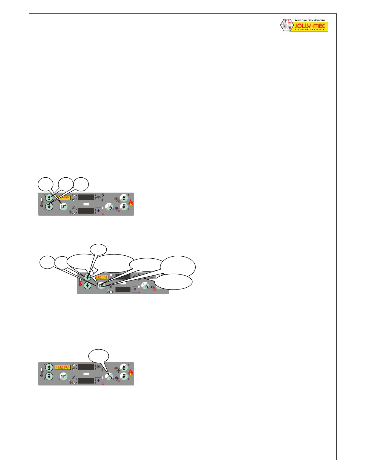
1.6.6 How to silence an alarm, STANDARD control panel
If an alarm appears on the display, to silence it and allow the fire to function it is necessary to proceed as follows:
N.B. If the fire goes out, it is not possible to re-ignite it until it has cooled down, wait for 10 minutes
and repeat the ignition sequence.
4”
Press key 4 for 4 seconds.
Press the SET key for one second.
Whilst the led are flashing:
• press key 1 to raise the temperature of the water in boiler.
•
press key 2 to lower the temperature of the water in boiler.
1”
Setting pump
start temperature
5”
1”
3 times
As far as A9
15 times
confirm
1"
Exit 2”
-
Page 12
Foghet water fireplace combined wood-pellet version with JOLLY ME 04 F burner 15
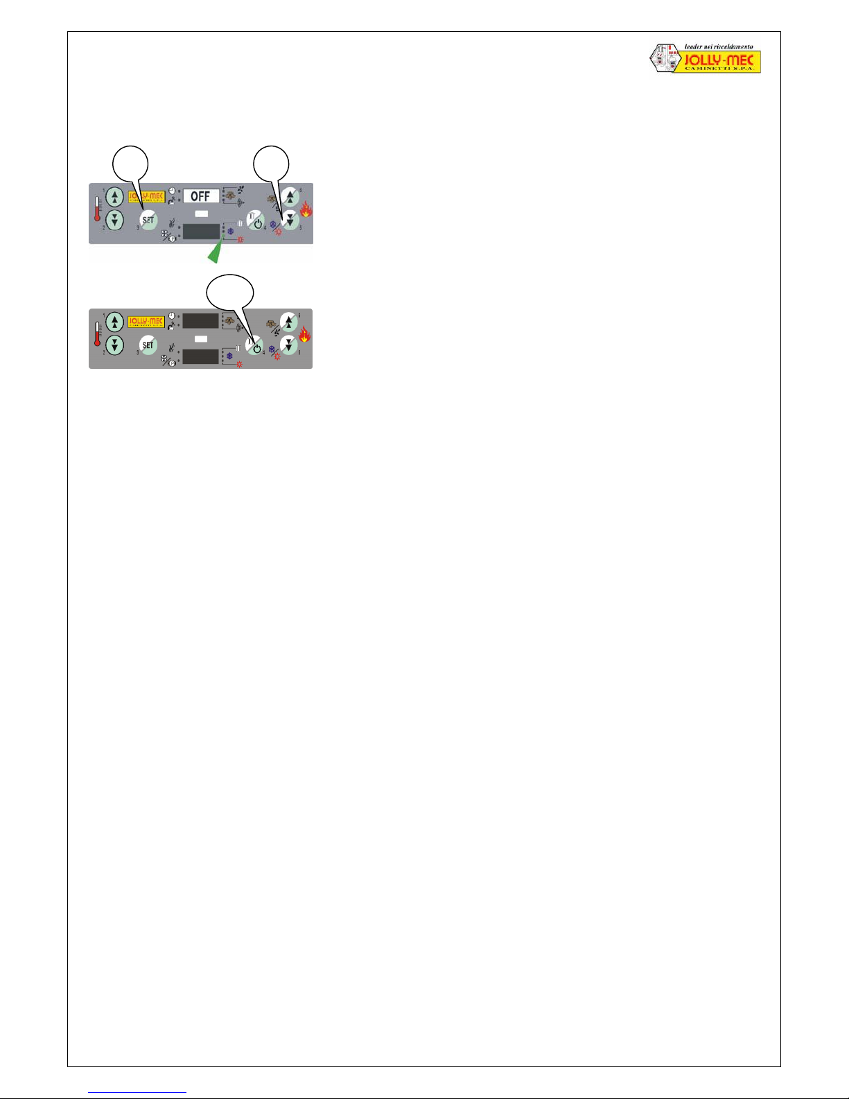
1.6.7 Summer mode, STANDARD control panel
If you want to use the fireplace in the Summer for hot domestic water:
For a more economical working, we recommend lowering the boiler water threshold temperature to 45C° - 55C°
N.B. if the fireplace is set to summer mode
IT IS NOT POSSIBLE TO PERFORM AUTOMATIC PELLET IGNITION
as the selector valve is closed for domestic water only
N.B. if the fireplace is set to summer mode
the chronothermostat is not enabled
If you want to use the chronothermostat in Summer as well, we recommend to set the WINTER mode, lowering the
threshold for the room temperature probe at min, so that the heating doesn’t start.
1” 1”
Select the summer operating mode
Press SET for 1 second.
Whilst the led are flashing press key 5 per 1 second.
Check that the green led is on (see green arrow).
To switch on the fireplace:
Press SET for 4 seconds.
4”
Page 13
16 Foghet water fireplace combined wood-pellet version with JOLLY ME 04 F burner
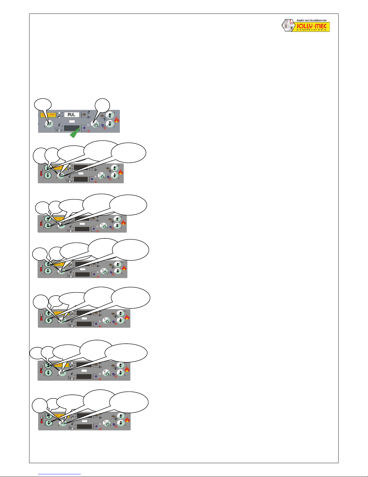
1.6.8 Correction of problems due to combustion STANDARD control panel
If, having installed the fireplace following all the instructions, after carefully cleaning the pellet hopper, the boiler unit, the
flue and the external air inlets, the pellet does not burn well (or you are using a pellet with different characteristics than
that used for testing the appliance), it is possible to adjust the flow of pellets through the charger (see page 29) and of
combustion air can be modified to achieve the correct combustion ratio and the best performance. The various
procedures to follow are outlined below. Comply with the indicated times when pressing the keys as shown in the images
and follow the correct sequence (from left to right).
If after a few hours burning, the colour of the flame changes (from yellow
it turns orange or red); activate a hopper cleaning cycle (the pellet rate
will be reduced to minimum and the combustion air will rise to maximum
for 2 minutes, PUL will be indicated on the display and the relative led
will come on). If the problem persists, follow the steps below.
If the window after 2-3 hours burning is excessively dirty, the pellet is not
burning well, increase the combustion air rate (automatic 20% increase
of combustion air at all output modes)
If little pellet enters the hopper, and the flame is uncertain and shaky
increase the pellet rate (automatic 20% increase at all output modes)
If there is excessive combustion air, raise the pellet until it falls out of the
hopper; reduce the combustion air rate. (automatic 20% reduction of
combustion air at all output modes)
If the pellet rate is excessive the hopper will fill up too much and the
pellet will not burn well, create black smoke and dirty considerably;
reduce the pellet rate (automatic 20% reduction at all output modes)
If the fire goes out when it is running in minimum or economy mode,
increase simultaneously the air and pellet rates (automatic 20% increase
at all output modes)
If during these various attempts, the combustion gets worse instead of
improving, it is possible to reset the appliance to the JOLLY-MEC factory
standard settings.
”
3 times
Scroll
to 00
confirm
"
5”
Resetting to factory standard settings
5”
1”
3 times
Scroll
to 03
confirm
"
Decrease combustion air by 20%
”
”
3 times
Scroll
to 05
confirm 1"
Increase air and pellet by 20%
”
1”
Manual hopper cleanin
g
5”
1”
3 times
Scroll
to 01
confirm
"
Increase combustion air by 20%
5”
1”
3 times
Scroll
to 02
confirm
"
Increase pellet by 20%
”
3 times
Scroll
to 04
confirm
"
5”
Decrease pellet by 20%
Page 14
Foghet water fireplace combined wood-pellet version with JOLLY ME 04 F burner 17
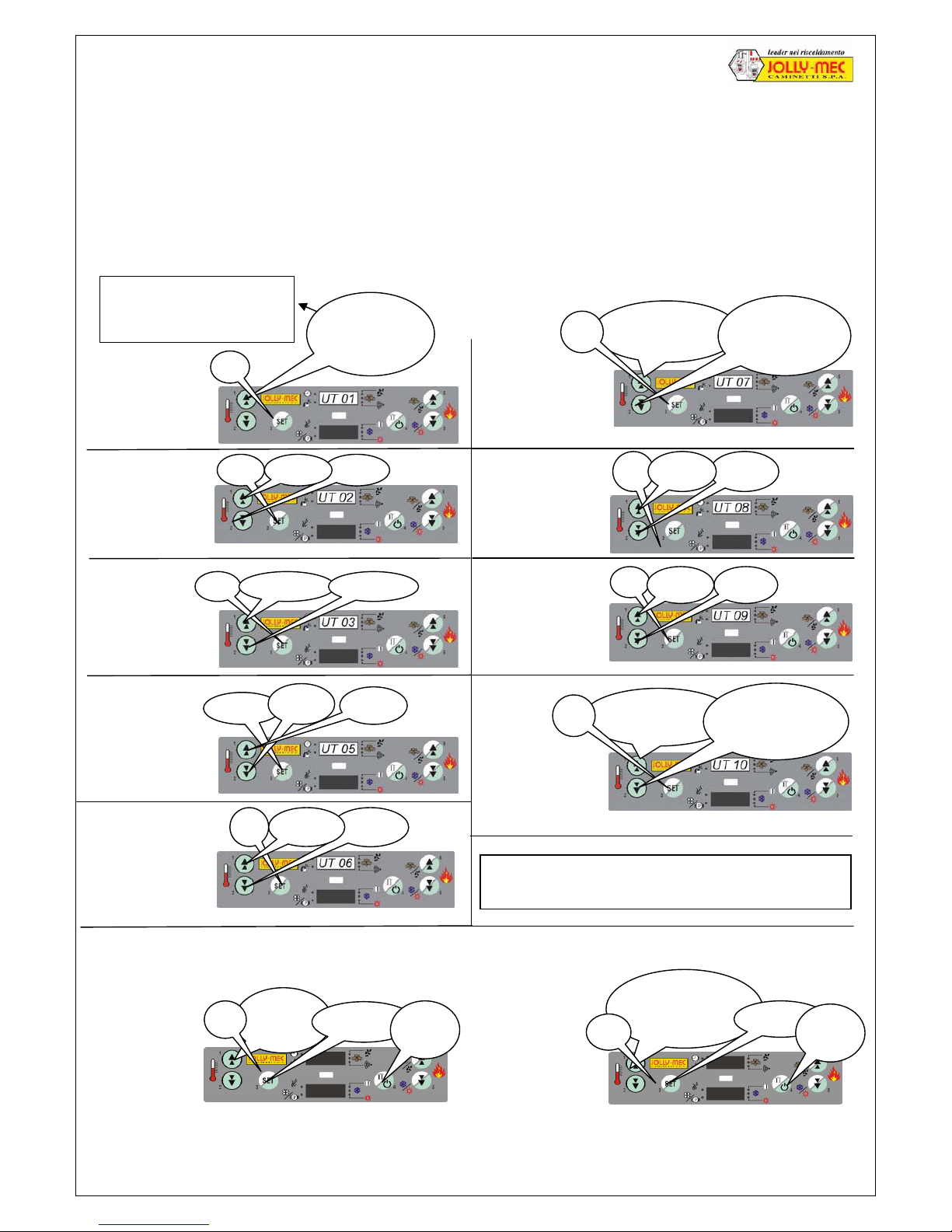
1.6.9 Time-controlled thermostat,STANDARD control unit
All STANDARD electronic control units are fitted with a timer-controlled thermostat which can be set to automatically
ignite and switch off twice a day seven days a week. It is possible to set it to ignite once or twice a day at the desired
times. The timer-controlled thermostat led indicates when it is activated. To programme the timer-controlled thermostat
proceed as follows:
Comply with the indicated times when pressing the keys as shown in the images and follow the correct sequence
(from left to right).
Press to
OFF
5”
confirm
1"
exit
Scroll until you
reach the current
day of the week
confirm
5”
1"
exit
To enable or disable the timer-controlled thermostat without losing the settings proceed as follows:
2
Set the
correct time
1” hour - hour +
1”
hour - hour +
1” Min
utes
+ Min
utes
-
2 times
hour +
hour -
1”
hour -
hour +
To cancel a wrong command press key 4 (ON/OFF)
for one second and re-programme as required
Scroll the days
of the week
1”
with ON or OFF to set the 7 days
Select the
function days
with ON-OFF
1”
hour - hour +
Scroll the days
of the week
1”
Select the
function days with
ON-OFF
with ON or OFF to set the 7 days
1
Setting the
current day
Scroll until you
reach the current
day of the week
5”
day01 = Monday day05 = Friday
day02 = Tuesday day06 = Saturday
day03 = Wednesday day07 = Sunday
day04 = Thursday OFF = disabled
3
Set the correct
minutes
4
Set the first
ignition time
5
Set the first
switch off time
6
Set the days
it must function
7
Set the second
ignition time
8
Set the second
switch off time
9
Set the days for the
second ignition
Disabling the
timer-controlled
thermostat whilst
maintaining the
memory (for
eventual reset)
Re-enable
timer-controlled
thermostat with
the previous
memory
N.B. The chronothermostat is disabled in Summer mode.
Page 15
18 Foghet water fireplace combined wood-pellet version with JOLLY ME 04 F burner
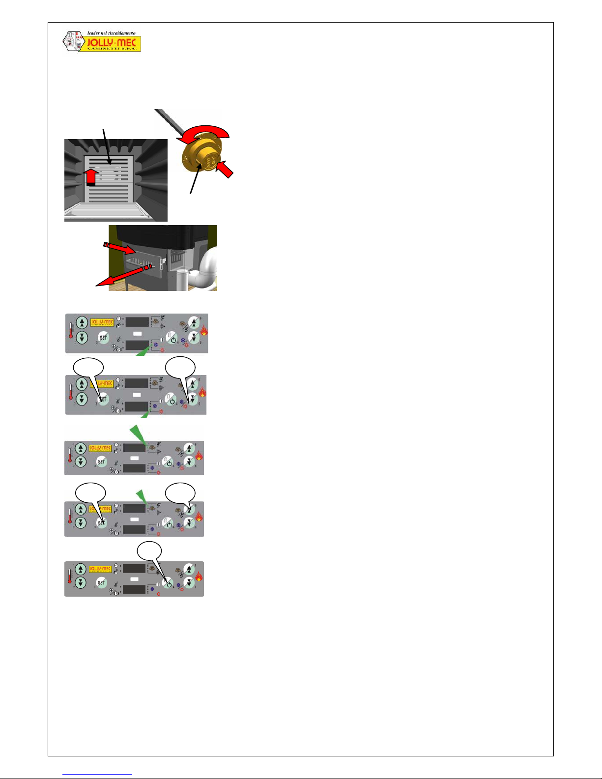
1.6.10 Wood Ignition, STANDARD control panel
Before igniting the wood fire it is necessary to complete some preliminary operations :
The fireplace’s capacity and the duration of the fuel are regulated by the quantity of combustion air and the flue
drought. This is done by regulating the quantity of the primary air to the ashpan (open or close the bottomgrate) and
open/close the fume register
The fireplace has an automatic primary combustion air control thanks to the CaldoControl device, which controls the
fume register to reduce the secondary combustion air passage once the temperature of the boiler water reaches 55
C°- 65 C°.
In order to have an output of 20,000 Kcal/h (23.2 kW), you need to burn 5-6 kg of wood an hour.
1. Clean the hearth, the burner hopper and empty the ashpan
2. Manually open the flue gas damper by rotating the knob until the
notch indicates position A and block it by pressing the knob until
the fastener screws click into place.
3. Move the cast iron bottomgrate located above the pellet burner
4. Open the bottomgrate on the ashpan.
5. Open Caldo Control by pulling the lever
6. Check that the control panel is set to winter mode (the relative led
must be on) see green arrow.
7. If the control panel is in summer mode (the relative led is on)
switch it to winter mode. Press the SET key for 1 second and
whilst the led flashes press key 5 for 1 second (the winter mode
led will come on) see green arrow
8. Check that the control unit is set to wood mode or the appliance
will ignite in pellet mode (the relative led must be on) see green
arrow.
9. If the control unit is in pellet mode (the relative led is on) switch it
to wood mode. Press the SET key for 1 second and whilst the led
flashes press key 6 for 1 second (the wood mode led will come on
and LE will be indicated on the display)
10. Press key 4 for 4 seconds to switch on the control panel
11. Load the wood into the fireplace and switch the fire on.
12. Close the door.
"
1"
1"
"
1"
Grate
Caldo
Control
Notch
Cast iron bottomgrates
Page 16
Foghet water fireplace combined wood-pellet version with JOLLY ME 04 F burner 19
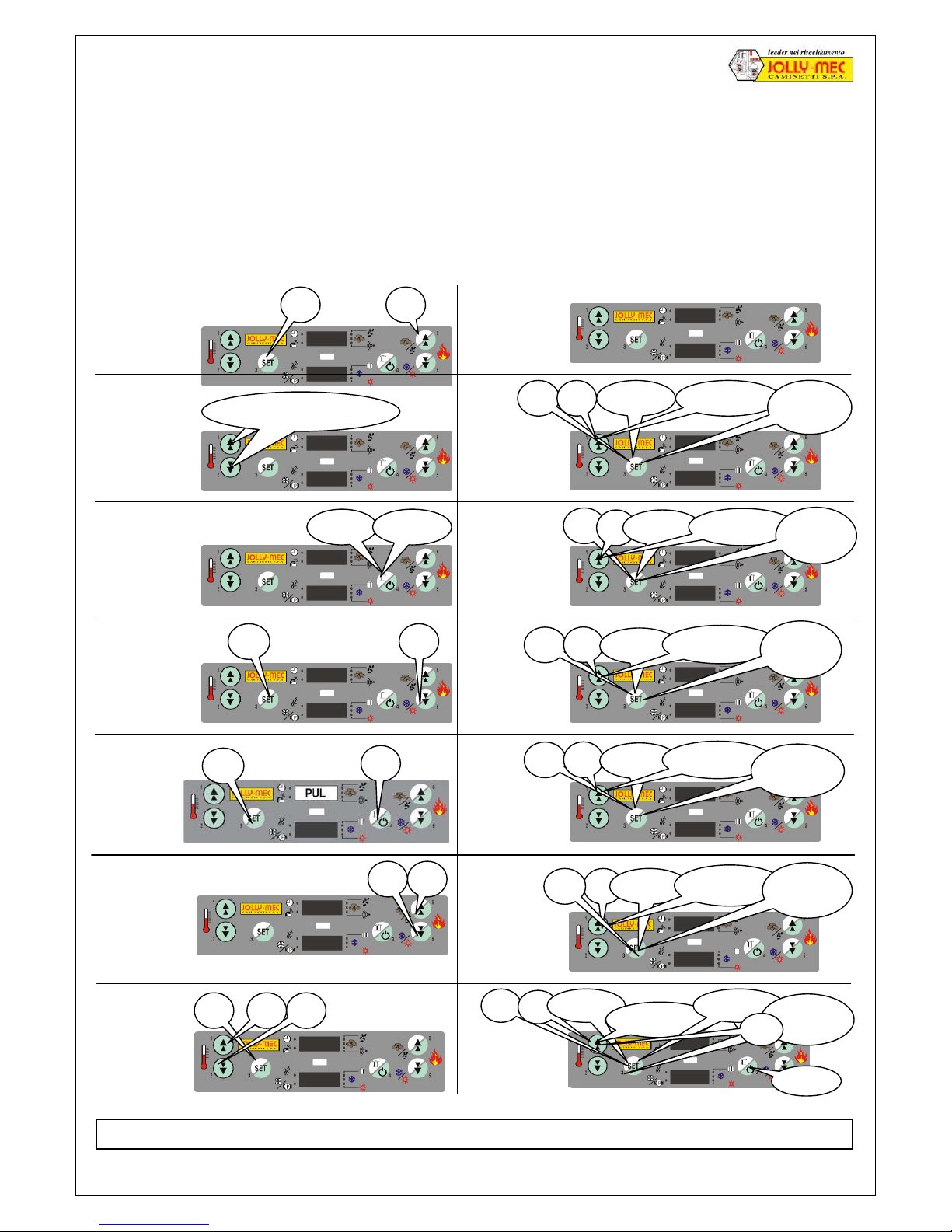
1.6.11 Summary of the main functions to use the fireplace performed by the STANDARD control panel
Comply with the indicated times when pressing the keys and work from left to right.
The pump starts when the boiler water temperature is higher than the temperature set in paragraph 1.6.5.
The ember bed phase is handled manually, both during enabling and disabling phases, and is useful to achieve
extremely low consumption rates nd when necessary quick manual ignition without the use of the resistance.
N.B. If the fire goes out, it is not possible to re-ignite it until it has cooled down, wait for 10 minutes and repeat the
ignition sequence. CHECK IF THE HOPPER NEEDS CLEANING EVERY DAY.
After each modification IT IS NECESSARY to enable the chronothermostat (because it is automatically disabled).
5” ON 5” OFF
1” 1”
1 Switching
from wood to
pellet mode
and vice-versa
5” 1” 3 times
As far as 02
1”
confirm
1”
1”
To cancel a wrong command press key 4 (ON/OFF) for one second
1” 3 times
As far as 00
1”
confirm
5”
5”
1”
3 times
As far as 04
1”
confirm
5”
1”
3 times
As far as 05
1”
confirm
Press simultaneously
5 Manual
Hopper
Cleaning
1”
1”
5”
1” 3 times
As far as 03
1”
confirm
6 To increase the output press key 6 (+)
To reduce output press key 5 (-)
Power 1
2
3
Ember bed 4
7 Setting the
Economy
threshold for
the boiler water
(recommended
60/75 C°)
1”
2 Manual pellet
loading and trial
loading
3 Ignition or
Switching Off
4 Switching
from Summer
to Winter mode
or vice-versa
8 Increase
combustion
air by 20%
9 Increase
Pellet 20%
10 Decrease
combustion
air by 20%
11 Decrease
pellet quantity
by 20%
12 Increase air
and pellet by
20%
13 Return
standard
correction and
modification
+
-
+
-
5”
1”
3 times
As far as 09
15 times
1”
2” exi
t
+/-
14 Setting
pump start
temperature
(recommended 55÷75 C°)
Page 17
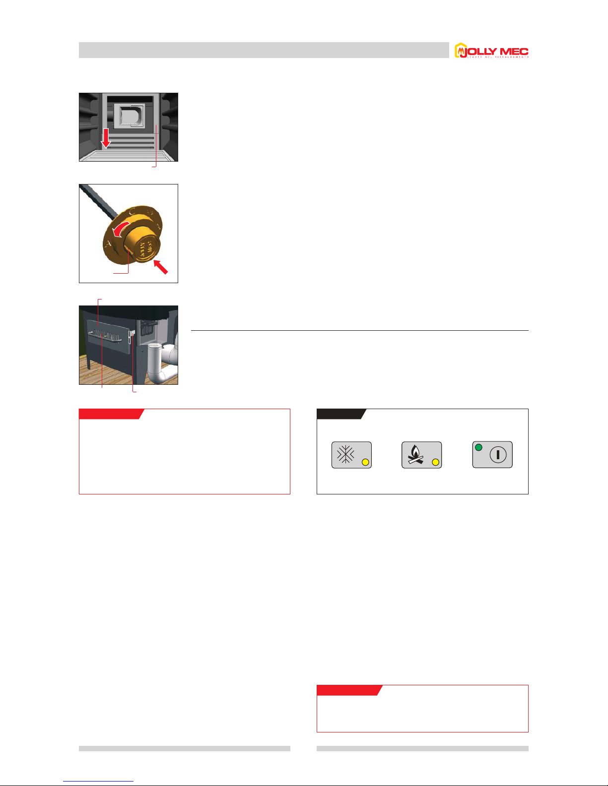
1.6 New-generation simplified electronic controller
17
1.6.12 Ignition in wood burning mode
For correct operation in wood mode, the ”SET WOOD AIR” function
must be set to the value 2 in the
Quick menu
.
The stove output and load duration are regulated by the amount of
combustion air; to adjust the amount, adjust the primary air of the
ash pan (opening or closing the grille).
The stove has an automatic draught adjustment by means of the
CALDO CONTROL (also adjustable manually), which operates
the damper to reduce the primary combustion air passage section
when the air reaches a temperature of around 70°C.
To obtain a heating power of 23.2 kW (20,000 Kcal/h), it is
necessary to burn 6-7 kg of wood per hour.
Cast iron grate
Notch
Cast iron grate Caldo Control
Ash pan
BUTTONS
ON
WINTER WOOD ON
WARNING!
To switch automatically from wood to pellet mode, the
damper must be set to 1/2,
and the burner will
temporarily operate with the grate over the burn pot.
WARNING!
NEVER LIGHT THE STOVE IN WOOD MODE WITHOUT THE
POWER CONNECTED.
Before lighting the pellet stove, a few preliminary operations are necessary:
1.
Clean the fire bed and empty the ash pan.
2.
Open the damper, turning the knob it until the notch is aligned with A, then lock it by pushing in the
knob to engage the locking screw.
3.
Move the cast iron grate over the pellet burner.
4.
Open the grille positioned on the ash pan.
5.
Open the Caldo Control by pulling the lever.
6.
Check that the controller is set to Winter mode (for heating and hot water production the corresponding
LED must be lit).
7.
Check that the controller is set to wood mode otherwise the stove will light in pellet mode (the
corresponding LED must be lit).
8.
Press ON.
9.
Load the wood and light the fire.
10.
Close the door.
•
Automatic switching from wood to pellet mode
With wood mode set, press the button WOOD again (the corresponding LED flashes) to activate
automatic switching from wood to pellet mode. When the wood is finished and the boiler water
temperature falls below the set limit, the burner starts automatically after 30 minutes.
Page 18
A
C
A
1
/
2
A
C
A
1
/
2
A
C
A
1
/
2
1.7
Optimising combustion and damper use
18
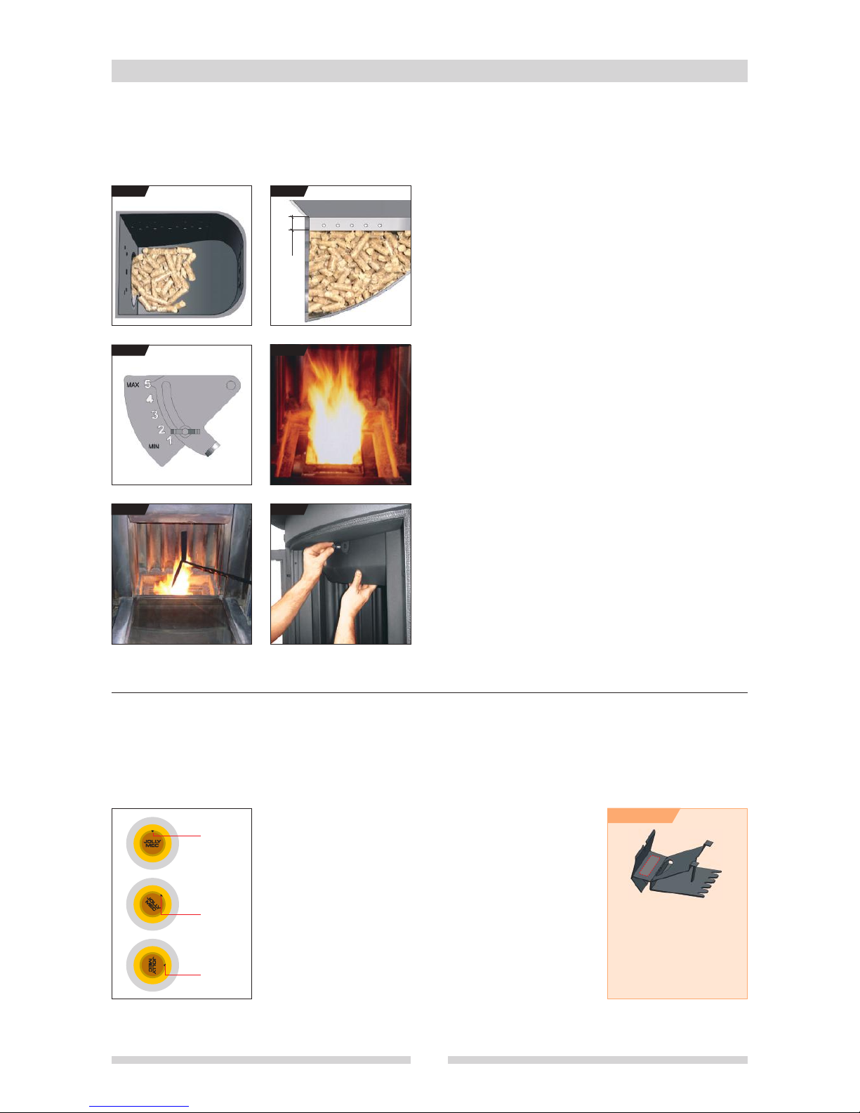
This stove/boiler offers excellent performance. When using pellets, for optimum operation without overloading the burner respect the
following rules, making use of the ”pellet feed control”.
•
Using the damper
The damper can be set to 3 positions: open, half-closed and closed. It allows the correct adjustment of combustion according to flue
draught (which also varies according to atmospheric conditions). The user should become familiar with damper use in order to optimise
stove operation. To adjust the damper:
• pull the knob;
• turn it until the notch is at the required position;
• push the knob in fully so that it engages the special locking screw.
CLOSED POSITION (C):
Operation in pellet mode only (with optimum draught)
HALF-CLOSED POSITION (1/2):
• During first lighting with pellets
• For automatic switching from wood to pellets
•
Operation in pellet mode with smoke on lighting and/or glass very dirty
•
Operation in wood mode at minimum (with simplified electronic
controller)
OPEN POSITION (A):
• Wood mode
• Operation in pellet mode with non-optimum draught
Careful adjustment of the damper is all-important for correct stove operation.
Step 1: manually load a small quantity of pellets using the
command on the electronic controller (see
FIG.1
). Do not
exceed the recommended quantity and make sure the burn pot
is secured by forcing it with the special screw.
Step 2: carry out lighting. At the end of automatic loading, in the
electrical element lighting stage, the quantity of pellets must never
exceed the level indicated (see
FIG.2
) in order to avoid violent
ignition.
Step 3: adjust the quantity of pellets according to their type and size
using the feed control
(see
FIG.3) and respecting the weights given
in the technical data; set the electronic controller to medium power;
close the damper and the Caldo Control; set the combustion air and
the pellets to 0%. The flame should be as in F
IG
.4. While burning,
the pellets must always remain below the upper holes of the burn
pot and the flame must be clear.
Step 4: when unburned fuel remains in the burn pot, use the
pointed end of the poker to break up the encrustations and then
the flat part to remove it and clean the combustion air holes
(see
FIG.5
).
Step 5: in case of incorrect combustion or lighting problems,
clean the burn pot, following the procedure in the plastic-coated
quick reference notice.
Step 6: about every 20 days, remove the upper baffle and clean
it. The combustion air percentage (%) must not be set below
-5% to avoid possible spontaneous combustion, dirtying
the boiler excessively and blackening the glass (see
FIG.6
).
2 cm
FIG.2
FIG.3
FIG.1
FIG.6FIG.5
FIG.4
ADVICE
If smoke escapes even when
opening the door slowly, with
damper open and the flue
complying with that given in
chap. 2.1, the precut part of the
smoke baffle shown in the figure
can be removed.
Notch
Notch
Notch
Page 19

1.8 Advice and warnings
With a zone heating system, when the stove is lit, it is essential
that at least one zone of the heating system is always open in
order to dissipate the heat produced (also in summer).
THE combustion fan must be cleaned at least once a year.
Only use original replacement parts; original replacement parts
are available from authorised dealers and Assistance Centres,
or directly from JOLLY-MEC.
There must be no other boilers, chimneys, stoves, fireplaces or
extractor blowers located in the same room as the stove.
When purchasing firewood, it is advisable to vary the sizes:
short lengths (30/32 cm) for quick lighting and longer lengths.
The greater the quality of the firewood, the greater its efficiency
and operation.
• If condensation forms inside the stove, this may be caused by
the following:
- the central heating circulating pump is set to start at too low
a temperature (it should set to start at 55°-60°C at the
lowest).
- the recirculation valve should open at around 45°
depending on the system head.
- poor flue draught (clean the flue).
- Insufficient combustion air (increase the air by means of the
combustion fan).
- boiler dirty: every 20-30 days, remove the smoke baffle and
clean the stove, particularly around the upper part where it
is connected to the flue. Use the flue brush to clean up as
far as the damper.
• If the glass turns black during normal pellet burning mode, this
may be caused by the following:
- poor flue draught (clean the flue or check that the flue
dimensions conform to requirements).
- Insufficient combustion air (increase the air by means of the
combustion fan).
- quantity of pellets in the burn pot (this varies depending on
the type of pellets used) is different from that given in the
technical data (chap. 1.2). Check that, at medium power,
the hourly pellet consumption; adjust the pellet feed rate , if
necessary, by way of the feed control. In the case of ignition
with quantity of pellets greater than that indicated on
page 20, contact the Technical Assistance Service.
If pellets have not been used for a long time (usually in the
spring-summer), the hopper, auger and burn pot must be
IT IS IMPORTANT THAT THERE IS ALWAYS WATER IN THE BOILER AT A PRESSURE OF 1 to 1.2 BAR WHEN COLD, AND THAT THE
MAINS CONNECTION FOR THE WATER REQUIRED TO COOL THE STOVE IS NEVER OBSTRUCTED.
completely emptied with the aid of a vacuum cleaner.
Then clean thoroughly to remove all pellet residue, which could
become compacted and block the auger or damage parts the
next time the stove is ignited.
To obtain a heating power of 23.2 kW (20,000 Kcal/h), it is
necessary to burn 6-7 kg of wood or 4-5 kg of pellets per hour.
Never ignite the stove, particularly in wood mode, without
electrical power.
The stove must not be used as an incinerator.
Only use recommended fuels, otherwise the warranty will be
invalidated.
Every 500-1000 kg of pellets loaded into the hopper, check that
there is no build up of sawdust on the bottom; if necessary,
remove all the sawdust (sawdust reduces the capacity of the
feed auger and creates operating problems for the stove).
The stove must always be closed, except when loading fire
wood, to prevent smoke escaping.
Check for any obstructions in the flue and the outside air inlets
before lighting the stove after a long period of disuse.
The firebox cannot be modified; any unauthorised modification
automatically invalidates the warranty and relieves the
Manufacture of any liability.
The stove must not be placed in direct contact with combustible
materials; the minimum distance is 20 cm.
Regular systematic maintenance is essential to maintain the
stove in perfect working order and optimum efficiency.
WARNING!
DO NOT TOUCH any parts of the firebox not covered by
the clad
ding, except the handles and controls, as they
can become very hot.
MORE CLEANING = MORE EFFICIENCY
19
Page 20
1.9 Cleaning the stove
20
Initially, for a few days during operation with pellets, check the burn pot to determine how often it needs cleaning. Before any cleaning,
always turn off the main switch and make sure the stove is cold.
•
Cleaning the burn pot
Removing the burn pot after loosening the locking screw with the
special wrench.
Carefully clean all the air holes in the burn pot with a pointed tool.
Make sure the burn pot support is clean (if the burn pot is not
correctly positioned and air escapes, the stove will not light or
operate properly; smoke could also enter the pellet hopper).
Position the burn pot correctly, pushing it to the left by means of
the locking screw located on the right side of the burn pot
container (make sure to tighten the screw).
•
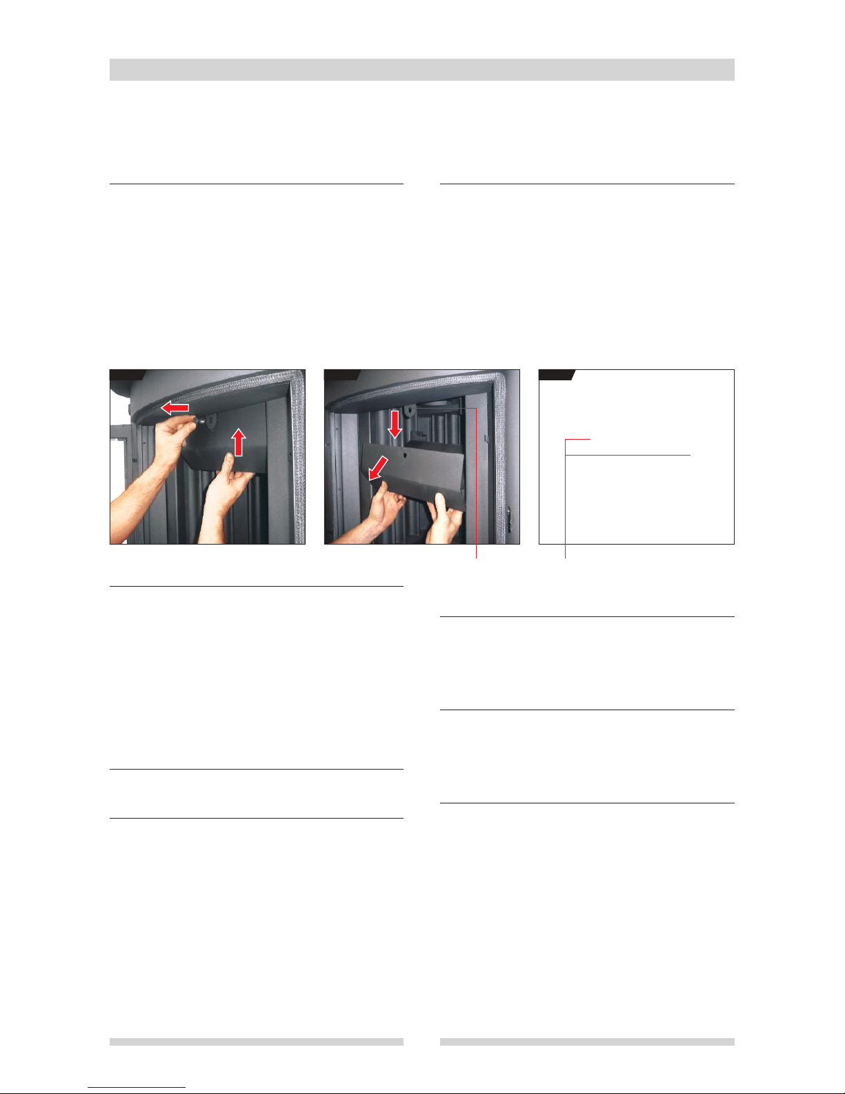
Cleaning the smoke baffle
Every 15-20 days, or even more frequently, depending on the
type of fuel used, flue draught and weather conditions, remove
the smoke baffle by lifting it up and pulling out the fixing pin
(
FIG.1
).
Lower and remove it (
FIG.2
). Carefully clean all the top part of
the stove up to and including the damper. Refit the smoke baffle
so that it rests on the rear support hooks obtained in the boiler
body (
FIG.3
) and insert the front pin in the hole on front of the
stove.
•
Cleaning the glass
When using the stove in pellet mode, clean the glass every day
with a damp sponge or a paper towel. If the glass becomes dirty
with black smoke, clean the burn pot or increase the combustion
air. When operating in wood mode, use specific products.
Do not use aggressive cleaning products that could damage the
paintwork.
If the stove requires more frequent cleaning, check the flue
draught and make sure the smoke baffle is clean (the minimum
draught must be 12 Pascal; do not use the stove if the draught
is less than the specified value).
•
Cleaning the ash pan
Empty periodically when necessary.
•
Cleaning the stove body
Remove the wood guard, cast iron grates and burn pot. Using
the flue brush and brush supplied, clean the corrugated sheet,
making sure the soot falls into the ash pan. Empty the ash pan
and carefully clean the box.
If necessary, use a vacuum cleaner to remove soot and ash.
Clean the pellet burn pot with a wire brush and a pointed tool.
Refit all parts correctly.
•
Cleaning the flue
Routine flue cleaning depends on the draught, stove use,
weather conditions and the type of wood or pellets used.
It is advisable to have the flue cleaned by a specialised
technician once a year, in autumn before lighting the stove.
•
Cleaning the pellet hopper
Every 500-1000 kg of pellets burned, empty the hopper and
remove any sawdust deposited on the bottom. Carefully clean
the bottom of the hopper.
In case of long idle periods, empty the hopper and the auger.
•
Cleaning the fans
Once a year remove the combustion fan and remove all dust
and dirt from the blades.
FIG.1 FIG.2 FIG.3
Lift the baffle and pull out the fixing pin Hole for fixing pin Rear support hooks
Page 21
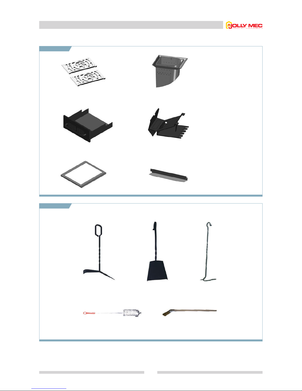
1.10 Parts that can be removed to clean the stove
21
A
B
C
D
E
F
AB
CD
EF
Cast iron grates
Pellet burn pot
Ash pan
Smoke baffle
Fire bed
Wood guard and removable
door support (curved front
model only)
Burn pot cleaning tool
Shovel Poker
Cleaning tools supplied
Flue brush Small brush
Page 22
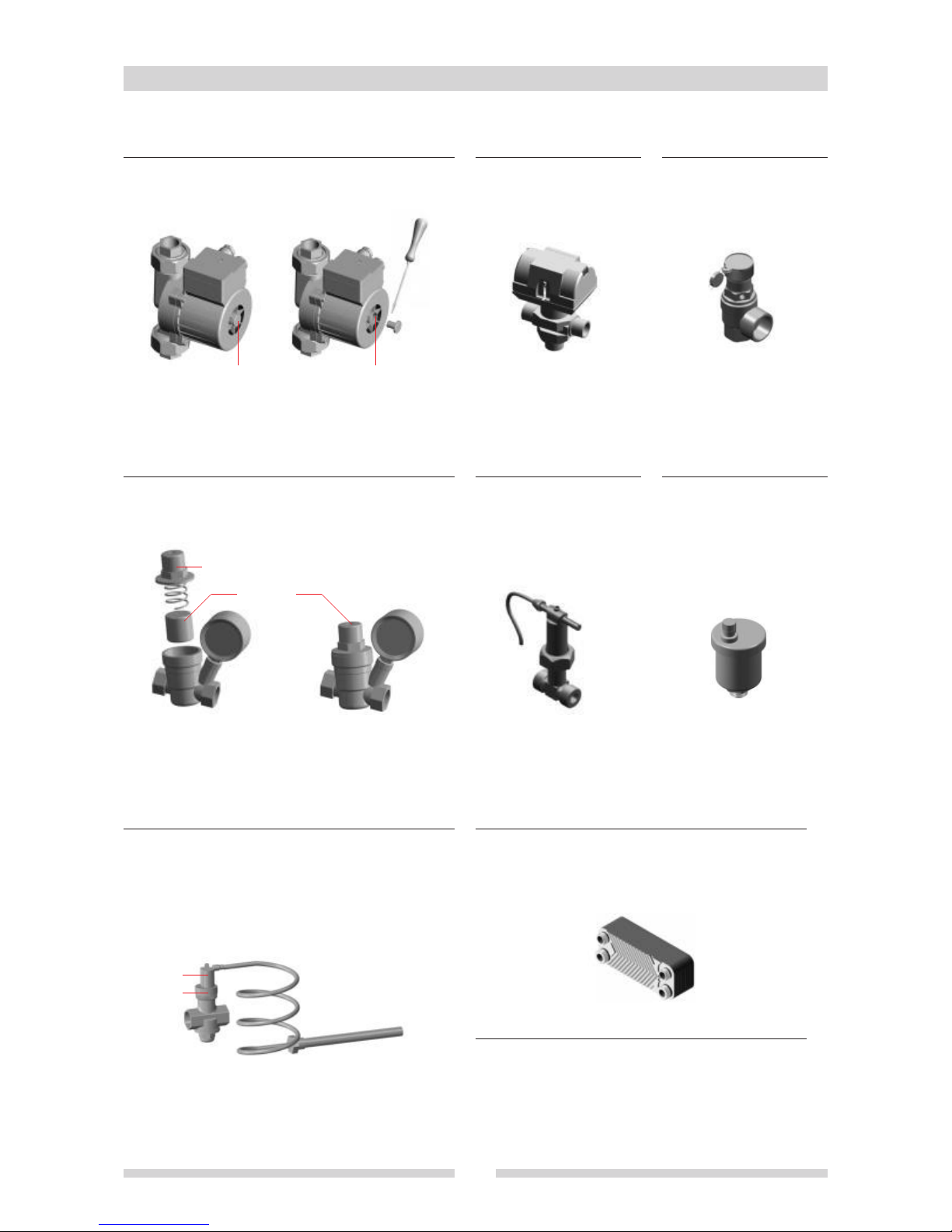
1.11 Plumbing kit components requiring routine maintenance
22
•
Pump
If the pump is locked up, to release it, remove screw 1 and turn the
internal screw 2 using a screwdriver.
•
Diverter valve
No maintenance required.
•
Pressure relief valves
To be cleared once a year.
1 2
•
Flow switch
The hot water pump starts
when a tap is opened. No
maintenance required.
•
Jolly bleed valves
Bleed air from the system if air
bubbles are present.
3
4 5
•
Pressure reducer with pressure gauge
For annual cleaning of the filter, remove the cap 3 using a pipe
wrench, extract the filter 4, clean it and replace it. Adjust the
pressure (1.0 to 1.2 bar) by way of screw 5.
6
7
•
Temperature relief valve
Button 6 is to be used to manually vent the temperature relief
valve in the event of loss of water due to boiling and operation
without water. Nut 7 to be slackened off in the event of water
loss (maximum 1/2 a turn) and monitored thereafter.
•
Plate-type heat exchanger
If there is a drop in the hot water flow rate, have the heat
exchanger either cleaned by a qualified technician (using
specific cleaning products) or replaced (replacement heat
exchangers are available from authorised dealers and Technical
Assistance Centres).
•
Expansion tank
Check once a year that the prefill pressure is 1.5 bar.
Page 23

1.12 Troubleshooting
23
WARNING!
Do not use the stove if the draught is not regular and combustion is not optimum!
The electronic controller does not
switch on
No pellets enter the burn pot
The auger does not rotate
The stove does not light automatically
in pellet mode
The pellets burn poorly forming
incompletely combusted residue in the
burn pot, the glass gets very dirty and
turns black
At minimum power, the stove always
goes off because not enough pellets
are fed
At minimum power, the stove always
goes off because too many pellets are
fed and do not burn
Smoke escapes when the door is
opened, the pellets burn poorly, or the
glass gets dirty (particularly when
used with wood)
• Check for possible power supply or mains problems.
• Check that the green connector of the display is correctly connected at the rear.
• The electronic controller is faulty.
• The electronic controller is in wood mode. Select pellet mode.
• The pellets are finished, refill the hopper.
• The auger is blocked by pellets that are too hard (only use pellets of the recommended type); free
the auger by turning the pin protruding from the burner casing.
• The gear motor is not powered (check and eliminate the causes).
• The gear motor does not turn even though powered (remove the gear motor, free the auger with a
screwdriver and refit the gear motor).
• The motor turns but the auger does not move. Replace the gear motor (broken gears).
• SUMMER MODE is set.
• The burn pot is dirty. Clean it thoroughly and refit correctly.
• The burn pot is not correctly positioned. Reposition and clamp it, tightening the locking screw with
the special wrench supplied
• The electrical element is faulty; replace the electrical element. In the meantime, light the stove
manually using firelighters (or similar products).
• The quantity of pellets fed into the burn pot at the various power levels does not comply with that
given in the Technical Data (see chap. 1.2). Check and correct.
• Insufficient flue draught (do not use the stove, it could be dangerous). Clean the flue and the stove
thoroughly.
• Pellet burn pot dirty. Clean it.
• Pellets damp. Replace with dry pellets.
• Insufficient combustion air; check that the combustion fan pipe is unobstructed and clean the fan.
• Insufficient combustion air setting. Increase the setting in the SET COMB. AIR function in the Quick
Menu.
• Too much sawdust on the bottom of the hopper. Empty the hopper and refill with new pellets. (every
500-1000 kg of pellets loaded, empty the hopper and remove all the sawdust deposited on the
bottom).
• Increase the pellet feed in the SET PELLET % function in the Quick Menu.
• Reduce the pellet flow rate in the SET PELLET % function in the Quick Menu.
• Increase the combustion air.
• If the stove is installed in a room in communication with a stairwell, close off the stairwell by installing
a door.
• There are other appliances that use room air, creating low pressure. Use the stove when the other
appliances are off.
• The outside air inlets and/or the flue are partially or completely obstructed. Clean or remove the
obstructions.
• Insufficient flue draught: there are horizontal sections or 90° bends, or the chimney cap is located
under the ridge of the roof (installation errors). Remove the precut part from the smoke baffle
(see chap. 1.7); replace the horizontal sections with sections at 45°; raise the chimney cap, or fit an
antiwind cap.
• Check that the flue conforms to the indications given in chap. 2.1, clean the flue and smoke baffle,
open the damper, open the door slowly. If after these operations smoke still comes out, eliminate
the precut part of the smoke baffle (see chap. 1.7).
PROBLEM CAUSE AND/OR CURE
Page 24

1.12 Troubleshooting
24
WARNING!
For alarms different from those listed, persistent problems or other problems not described above, contact the Technical
Assistance Service
.
No hot water flows when a tap is
opened
Little hot water flow
Excessive condensation forms inside
the stove
The circuit breaker trips
The radiators do not get hot even
if the water in the boiler is hot and the
pump is running
• THE electrical power is disconnected, reconnect it; or the controller is set to OFF; switch it on by
pressing ON.
• The hot water flow tap is closed; open it.
• The diverter valve does not operate; check that it is connected correctly and not stuck.
• The pressure in the boiler is too low and the flow switch provides no contact. Return the pressure
to 1 to 1.2 bar when cold by way of the pressure control-reducer and/or by checking the system.
• The flow control switch is disconnected, dirty or faulty; reconnect it or replace it.
• The pump does not star t; check that it is connected correctly and not stuck; if necessary, free it using
a screwdriver (as shown in chap. 1.11).
• The plate-type heat exchanger is clogged with limescale; remove it and clean it or replace it.
• The pressure inside the boiler is too high and the 2.5 bar pressure relief valve discharges
continuously. Restore the pressure to 1-1.2 bar when cold using the pressure regulator-reducer.
• The recirculation valve is not sufficiently open; open it.
• The temperature at which the pump starts is set too low; increase the temperature setting.
• When the stove is first used, or after a long period of disuse, condensation may form in the igniter;
carry out one or more manual cleaning operations by way of the controller to dry out the
condensation in the igniter, or light the stove manually.
• The diverter valve does not operate; check that it is connected correctly and not stuck.
• There is air in the system; bleed all the radiators, the pump and the boiler.
PROBLEM CAUSE AND/OR CURE
No pellets
Boiler overheating
Fume probe
Boiler probe
Room probe
Combustion air blower stopped
Fume exhaust
Second ignition attempt failed
Low pressure
High pressure
• The stove hopper (or supplementary hopper) is empty. Add pellets.
• The water temperature is too high. The pellets or burner go out. Zone valves may be closed or
problems in the system. Check and clean.
• Fume temperature probe faulty or not properly connected. Check the connection or replace the probe.
• Water temperature probe in stove faulty or not properly connected. Check the connection or replace
the probe.
•
Room temperature probe faulty or not properly connected. Check the connection or replace the probe.
• Blown fuse. Check and replace.
• Safety thermostat activated. Empty the ash pan and clean the surface under it. Wait until the stove
has cooled then try again.
• Combustion fan faulty. Contact the Technical Assistance Service.
• Pressure switch activated. Check the flue.
• Empty the burn pot, check the gear motor and the electrical element. Try lighting again.
• System pressure below 0.5 bar (for sealed systems). The stove goes out. Increase the pressure by
automatic filling, or clean.
• System pressure greater than 2.4 bar. The stove goes out. Reduce the pressure set for automatic
filling and drain the boiler via the 2.5 bar pressure relief valve until the pressure falls to between 1
and 1.2 bar.
PROBLEM CAUSE AND/OR CURE
•
Main electronic controller alarms (see par. 1.6.7)
Page 25
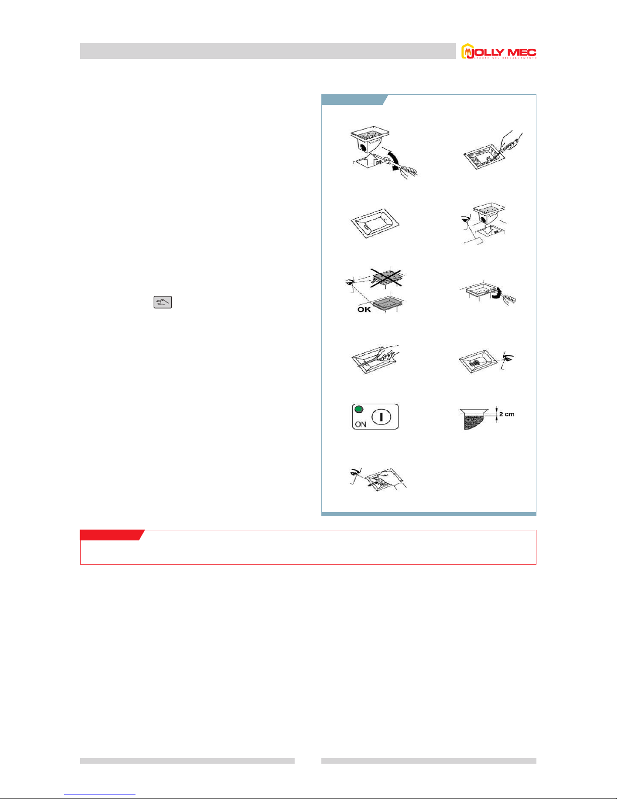
1.12 Troubleshooting
25
If the stove fails to light after the second attempt, proceed as
follows:
1. Remove the burn pot, loosening the locking screw with the
wrench supplied or pliers.
2. Clean and scrape the sides, clean all the holes.
3. Clean the burn pot chamber.
4. Refit the burn pot, paying attention to the pellet feed hole.
5. Make sure the upper flange is perfectly positioned on the
support surface.
6. Secure the burn pot with the locking screw using a wrench
or pliers.
7. Using the special wrench or a nail, make sure the hole in the
burn pot and the hopper is aligned.
8. Press the button to manually load the stove until the
pellets start entering
9. Before pressing the ignition button make sure the burn pot is
empty except for just a few pellets on the bottom (
FIG.8
).
Never light the stove if there are more pellets.
THE STOVE can now be lit.
10. Press the ON button on the electronic controller (
FIG.9
) to
light the stove.
11. On pressing the ignition button, the electronic controller
AUTOMATICALLY loads pellets up to 2 cm below the rim of
the burn pot; the electrical element then starts the pellet
igniting stage.
WARNING!
If the lighting cycle fails again, contact the Technical Assistance Service.
1. 2.
3. 4.
5. 6.
7. 8.
9.
11.
10.
Page 26
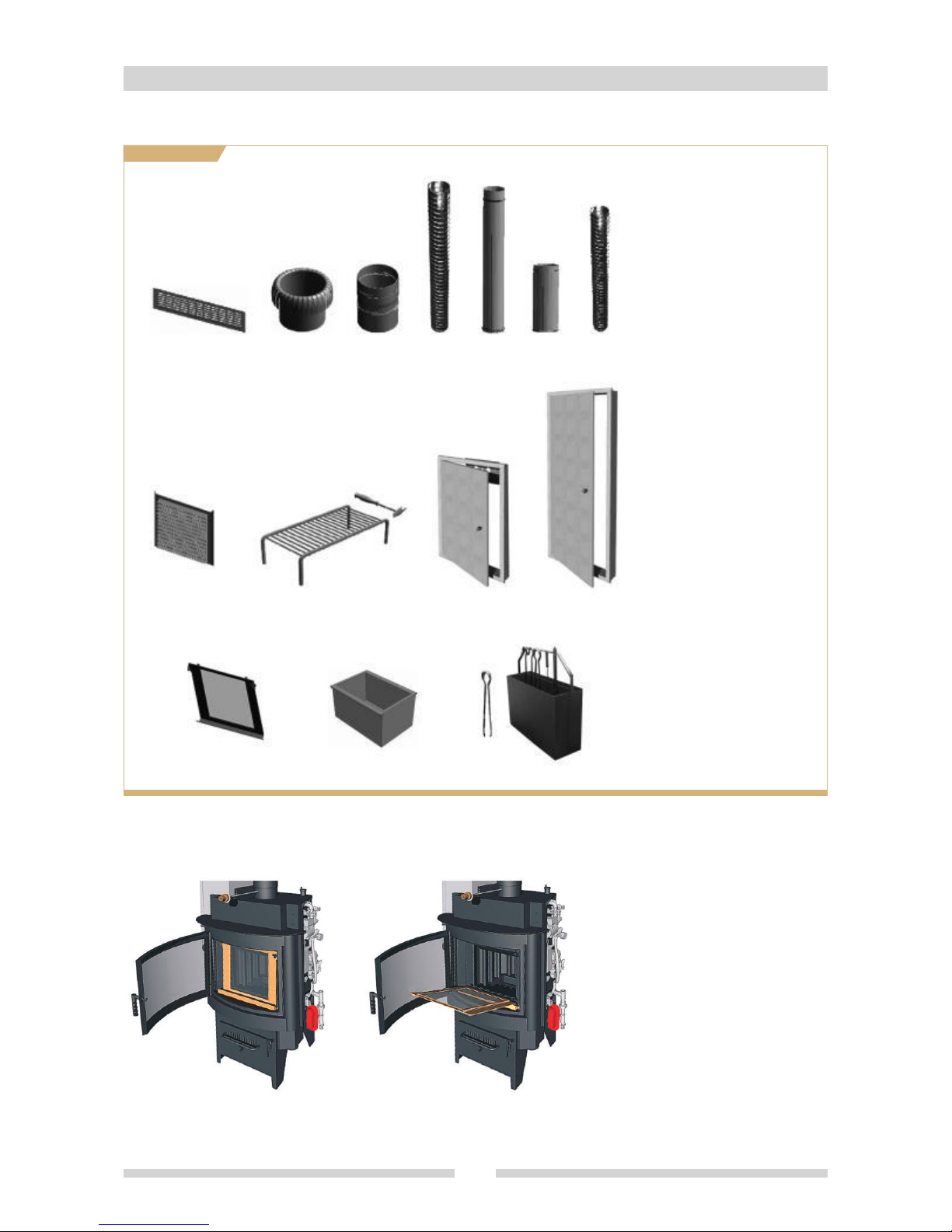
1.13 Optionals
26
A
B
C
D
E
F
G
H
I
J
K
L
M
N
A
H
LM N
IJK
BCDEFG
Hood vent grille
400x100 mm
Universal flue connection
MF connection for
Ø 150 mm double wall
flexible pipe
Ø 150 mm double wall
flexible stainless steel flue
Ø 150 mm smooth stainless
steel flue
Connection for Ø 150 mm
rigid pipe
Ø 80 mm aluminium ducting
for combustion air fan
230x230 mm grille for
outside air inlet
Stainless steel meat grill
with removable handle
(320x190x100 mm)
Hood door for pellet feed
Side panel door for
inspection and various
maintenance
Second flap door to facilitate
cleaning (for curved front
model only)
Ash box and wood holder
Holder for second door
(optional for curved front
model only) complete with
spring and stove cleaning
accessories (standard)
• Open the outer door.
• Insert the pins of the removable door in the
special holes obtained in the support,
pushing it on one side.
• Close the removable door using the poker,
engaging it with the hook provided at the top
right.
• Close the outer door.
•
To fit the removable flap door (optional for curved front model only)
Page 27
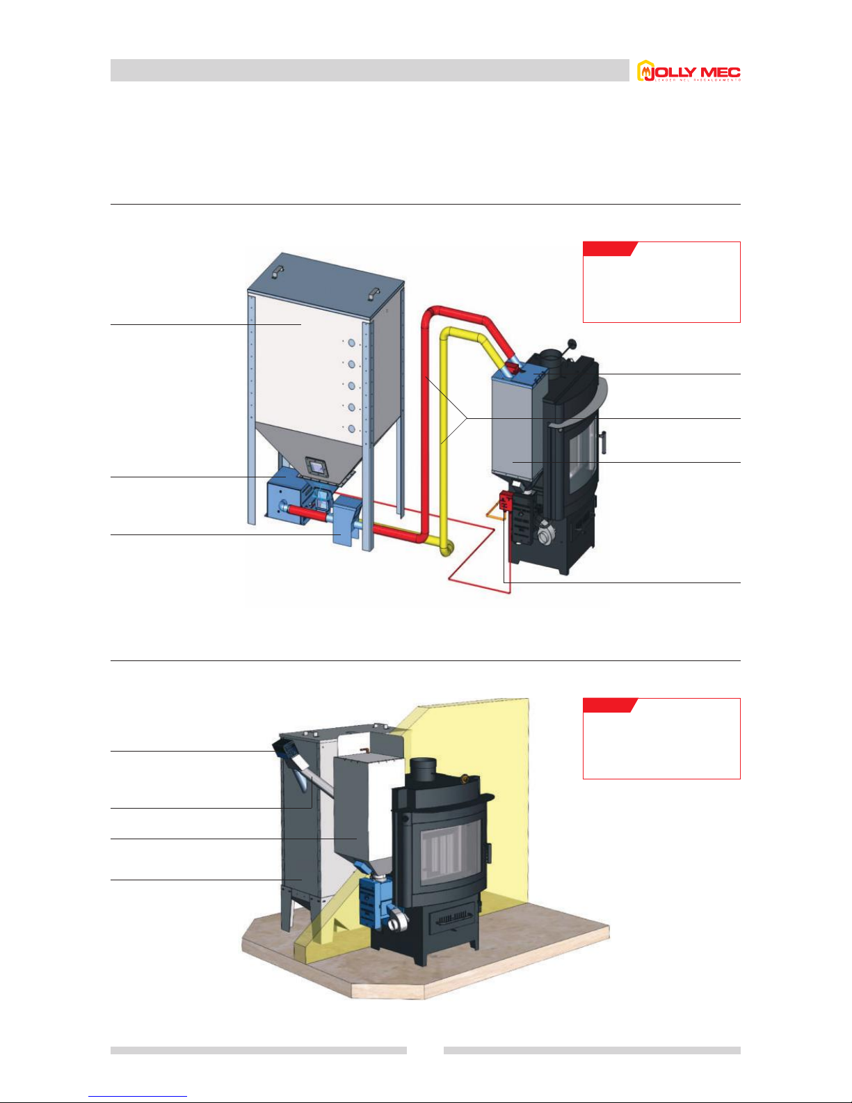
1.14 Larger capacity supplementary pellet hoppers
27
For a longer burn time, it is possible to install a supplementary pellet hopper, available in various capacities according to needs. The
pellets can be conveyed in two ways: by auger or with pneumatic conveyance.
•
Pellet hopper with pneumatic conveyance
Example with larger pellet hopper positioned in a room distant from the Foghet, with pneumatic conveyance.
•
Pellet hopper with auger
Example with larger capacity pellet hopper positioned in a room adjacent to the stove.
NOTE!
The downward inclination of the
pellet conv
eyance pipe (PVC)
must never be less than 45°.
NOTE!
Max. conveyance distance:
28 metres
Max. height:
8 metres
.
Larger capacity pellet hopper
(400 kg or 700 kg)
Pellet feed auger with gear motor
Larger capacity pellet hopper
(400 kg or 700 kg)
Standard pellet hopper, 46 kg
capacity
ø 63mm PVC connection pipes
Special lid
Flexible pipes
in PVC ø 50 mm
Standard pellet hopper,
46 kg capacity
Pneumatic conveyance
control unit
Pneumatic conveyance fan
Safety device with filter
Page 28

1.15 Pellet quality
28
IT is important to select pellets that are free of dirt and impurities.
The Pellet Producers’ Association has established standards for
producers of wood pellets. Ask your dealer for the best type of
pellets.
STOVE performance depends very much on the type and
quality of the wood pellets used. The efficiency and heating
capacity of the stove will vary according to the quality of the
wood pellets used.
Store pellets at a distance of at least 1 m. from the stove.
Do not use pellets that are very hard and of different sizes: the
mechanical parts are sized and tested for use with pellets
having the above characteristics.
JOLLY-MEC CAMINETTI S.p.A. recommends using the same
type of pellets as those used to test the stove, since combustion
parameters vary from pellets to pellets.
JOLLY-MEC CAMINETTI S.p.A. declines any liability for
malfunctioning, faults or problems due to the use of nonrecommended pellets.
As JOLLY-MEC CAMINETTI S.p.A. does not have control over
the quality of pellets used, it declines any liability for problems
caused by the use of non-recommended pellets.
WARNING!
THE QUALITY OF THE PELLETS IS VERY IMPORTANT. PLEASE READ THE NEXT PAGE CAREFULLY.
Dust 1% max. through 3.2 mm screen
Density 640 kg/m3min
Dimensions diameter 6 mm; max. length 25 to 40 mm
Ash content 1% max
Moisture 8% max
Heating power 5,200 kWh/kg
STANDARD PELLET CHARACTERISTICS
WARNING!
Any fault or malfunction due to the quality or quantity of
pellets used (see chap.
1.8) will not be covered by the
warranty.
Page 29

1.16 Use and keeping of the installation and maintenance card
29
•
Card recipients
The installation and maintenance card is intended for users responsible for stove operation; particular attention must be paid the parts
concerning safety.
•
Purpose of the card
The card contains information on the correct use of the stove, according to the purposes for which it was designed and built.
It also provides information about weights, commissioning, repair and maintenance of the stove in compliance with the limits laid down
by the Manufacturer, specified inside the card.
•
Keeping the card
The installation and maintenance card is an integral part of the stove and must be kept until scrapping of the same.
It must be kept in a safe and dry place away from direct sunlight, and near the stove so that it is always readily available for reference.
If lost or damaged, the user should request a copy from the Manufacturer.
•
Updating the card
The installation and maintenance card reflects the state of the art at the time the stove was marketed. The Manufacturer reserves the
right to make changes to the stove, and consequently to the relevant card, without having to update previous editions.
The user can always request information and updates which, when issued, become an integral part of the installation and maintenance
card.
If selling or transferring the stove, the user is requested to also give the new owner the card and in any case to inform the Manufacturer,
so that the new owner can receive subsequent supplements.
•
Cases relieving the Manufacturer from liability
The Manufacturer is relieved from any liability in the following cases:
a) improper use of the stove.
b) use not intended by specific national regulations.
c) incorrect installation.
d) feed defects.
e) failure to carry out maintenance as prescribed.
f) unauthorised modifications or operations.
g) use of replacement parts that are non-original or not specific to the model.
h) total or partial failure to follow the instructions.
i) exceptional events (e.g.: breakage due to natural disasters).
j) damage caused by electrical power cuts, sudden fluctuation of supply voltage, electromagnetic fields.
k) the use of pellets with characteristics different from those recommended in this card.
Page 30
1.17 Warranty
30
The Warranty Certificate is based on the Warranty Terms given below. It is valid to all intents and purposes only if sent to JOLLY-MEC
CAMINETTI S.p.A. within and not later than one month from the date of purchase. All parts of the Warranty Certificate must be
filled in clearly and correctly. If sending this sheet by fax, please use the number +39 035-8359200.
For any technical requirements or servicing requests, please contact the Call Center of our Sales Support Office at the number
+39 035-8359204, or e-mail [email protected].
•
Warranty terms
1. Duration: JOLLY-MEC CAMINETTI S.p.A. guarantees the
boiler body for 5 years, and every other individual part for
2 years, as required by law, excepting those parts subject to
wear due to use (glass, cast iron grates, ignition electrical
element and burn pot). The accessories (electrical, etc.) will be
covered by the warranties provided by the various
manufacturers.This warranty is valid only if the stove is installed
and used according to the instructions given in the manual
supplied, which the purchaser declares to have received and
read. Any fault or malfunction due to the quality of the pellets
used will not be covered by the warranty.
JOLLY-MEC CAMINETTI S.p.A. reserves the right to make
improvement modifications without prior notice.
2. Exclusions: The Customer is not covered by the warranty in
the following cases:
a)
if the data given on the ”Warranty Certificate” does not
correspond to a product sold by JOLLY-MEC CAMINETTI S.p.A.
b) if the ”Warranty Certificate” is incomplete or not filled in
correctly
c) if the cause of the fault is not due to defects in the product but
to external factors, such as:
- improper use of the product;
- use not envisaged by the specific national regulations;
- incorrect installation;
- feed defects;
- failure to carry out maintenance as prescribed;
- modifications or operations not duly authorised;
- use of non-original replacement parts or not specific to the
model;
- total or partial failure to follow the instructions or complaints
that do not conform to the constructional characteristics of
the product;
- exceptional events;
- damage caused by power failures, voltage rushes,
electromagnetic fields.
3. Variation: The right to the warranty undergoes variations with
regard to the 5 year duration indicated in point (1) if the
”Warranty Certificate” is not received by JOLLY-MEC
CAMINETTI S.p.A. within 30 days of the date of purchase of the
product. In this case, the 2-year warranty period will start from
the date of purchase by the Customer.
4. Operations not covered by the warranty: If the Customer
requests any assistance different from that provided for in the
”Warranty Terms” he shall be required to pay the corresponding
cost calculated on the basis of the prices normally applied by
the authorised Technical Assistance Centre.
5. Transferability of the warranty: The warranty cannot be
transferred to third parties and applies only to the first
purchaser.
WARNING!
To be entitled to replacement of parts or the assistance of
our technicians under the warranty, a copy of the receipt or
purchase invoice MUST be attached to the Warranty
Certificate. The warranty comes into effect only from the
moment JOLLY-MEC CAMINETTI S.p.A. receives the
Warranty Certificate duly filled in and sent within the terms
and methods indicated in point (3).
1.18 Assistance Service
Should you require support, contact the dealer who supplied the product or the JOLLY-MEC CAMINETTI S.p.A. After-Sales Technical
Service Dept.
JOLLY-MEC CAMINETTI S.p.A. - Via Fontana, 2 - 24060 Telgate - BG - ITALY
tel: +39 035 8359204 - fax +39 0358359200 - www.jolly-mec.it - [email protected]
Page 31
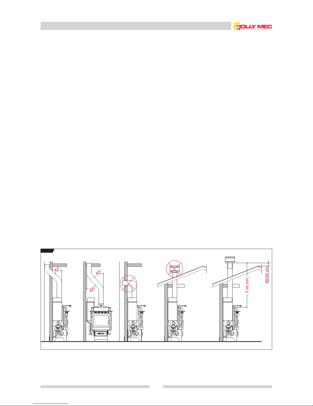
2.1 Flue
31
The flue is an all-important element for efficient stove operation.
The cross section of the flue must be that indicated in the stove
technical characteristics. Every stove must have its own flue,
excluding other emissions (stoves, boilers, fireplaces, etc.)
The dimensions of the flue depend on its height, to be
measured from the stove to the bottom of the chimney cap.
To ensure adequate draught, the fume outlet area of the cap
must be double the cross section area of the flue.The pipe used
to exhaust the fumes generated by the natural-draught stove
must:
- be fumetight, impermeable and adequately insulated
according the conditions of use (see UNI 9615).
- be made from materials able to withstand the normal
mechanical stresses, heat, and be resistant to the action of
fumes and possible condensate.
- be mainly vertical, with deviations from the axis not exceeding
45°.
- be at an adequate distance from combustible or flammable
materials (by means of an air space or suitable insulation)
- preferably have a round internal section: square or
rectangular sections must have rounded corners with radius
of at least 20 mm.
- have a uniform, free and independent internal section.
-
have the rectangular sections with a max. ratio between the sides
of 1.5:1.
An antiwind-type cap is advisable. If the flue is installed
externally, it must be insulated to prevent the cooling of fumes
and the formation of condensate. The same applies to the
section from the roof to the chimney cap.
For the connection between the flue and the stove, or in the
presence of branches or bends, or for easier, quick and safe
installation, it is advisable to use double wall stainless steel pipes
without insulation inside hoods. Non-combustible materials
resistant to the fumes and their possible condensate must be
used for installing the fume ducts.
The use of asbestos cement pipes to connect appliances to the
flue is prohibited.
The fume ducts must not cross rooms in which the installation
of combustion appliances is prohibited. The fume ducts must be
installed in such a way as to ensure fume tightness when the
stove is in negative pressure operating conditions and to avoid
the formation of condensate and its conveyance to the unit.
Horizontal sections should be avoided as much as possible.
For exhaust pipes which must reach ceiling or wall outlets that
are not co-axial with respect to the stove fume outlet, changes
of direction must be made using open elbows not exceeding
45° (see
FIG.1
).
Do not use elements sloping in the other direction. The exhaust
pipe must enable removal of soot and cleaning by brush. The
exhaust pipe must have a uniform cross section. Any changes
in section are only permitted at the generator outlet; reduction
adapters must not be used at the connection with the flue.
Do not route other air supply and system pipes inside the
exhaust pipes even if the latter are over-sized.
Do not support the weight of the flue on the stove/fireplace
connection. Use special brackets or separate supports.
Other stoves, fireplaces, boilers or air extractors must not
be installed in the same room.
Minimum height of exhaust pipe: 3 metres.
FIG.1
Page 32
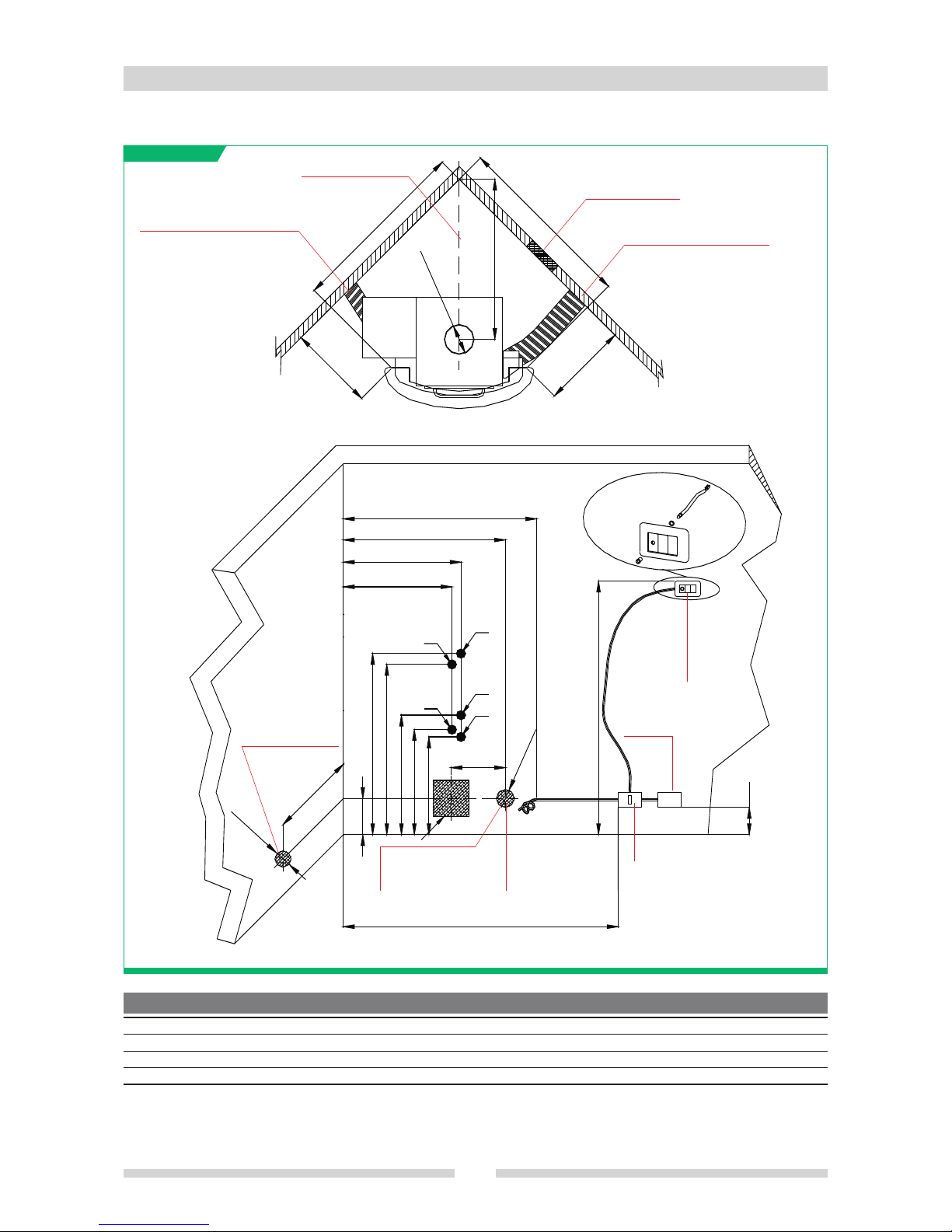
2.2 Prearrangement for connections and air inlets of the stove positioned in a corner
32
1000
940
660
580
540
200
950
Ø100
300
Ø100
1400
150
1400
A
A
B
C
C
Ø 150
D
E
F
G
a
b
d
c
e
Centre line
Air inlet (mandatory)
Caldo Control ducting (optional)
Pellet burner fan ducting (optional)
Fan outside air inlet
(optional)
Power supply
220V 50Hz
All measurements are in millimetres (mm)
a
b
c
d
e
Mains water inlet 1/2”
Pressure relief valv
e discharge 3/4”
Hot water flow 1/2”
Heating flow 3/4”
Heating return 3/4”
Ambient
temperature
or ambient
thermostat
probe
Omnipolar switch
Outside air inlet for Caldo
Control (optional)
Outside air inlet 200x200
mm (mandatory)
The positions of the holes for the fan and Caldo Control ducting can also be moved provided they remain inside the covering.
For firewood-pellet Foghet stoves it is mandatory to have the three doors indicated in par. 1.4 to permit loading pellets, servicing the
pellet burner and the plumbing kit.
DO-IT-YOURSELF 14300 1000
1030
1066
905
884
927
977
745
474
504
539
375
1050
1080
1100
950
920
950
980
820
690
730
760
650
640
680
710
600
14200, 14000, 14500
14600
14000, 14100 (mod. wood)
COVERING art. A B C D E F G
Page 33
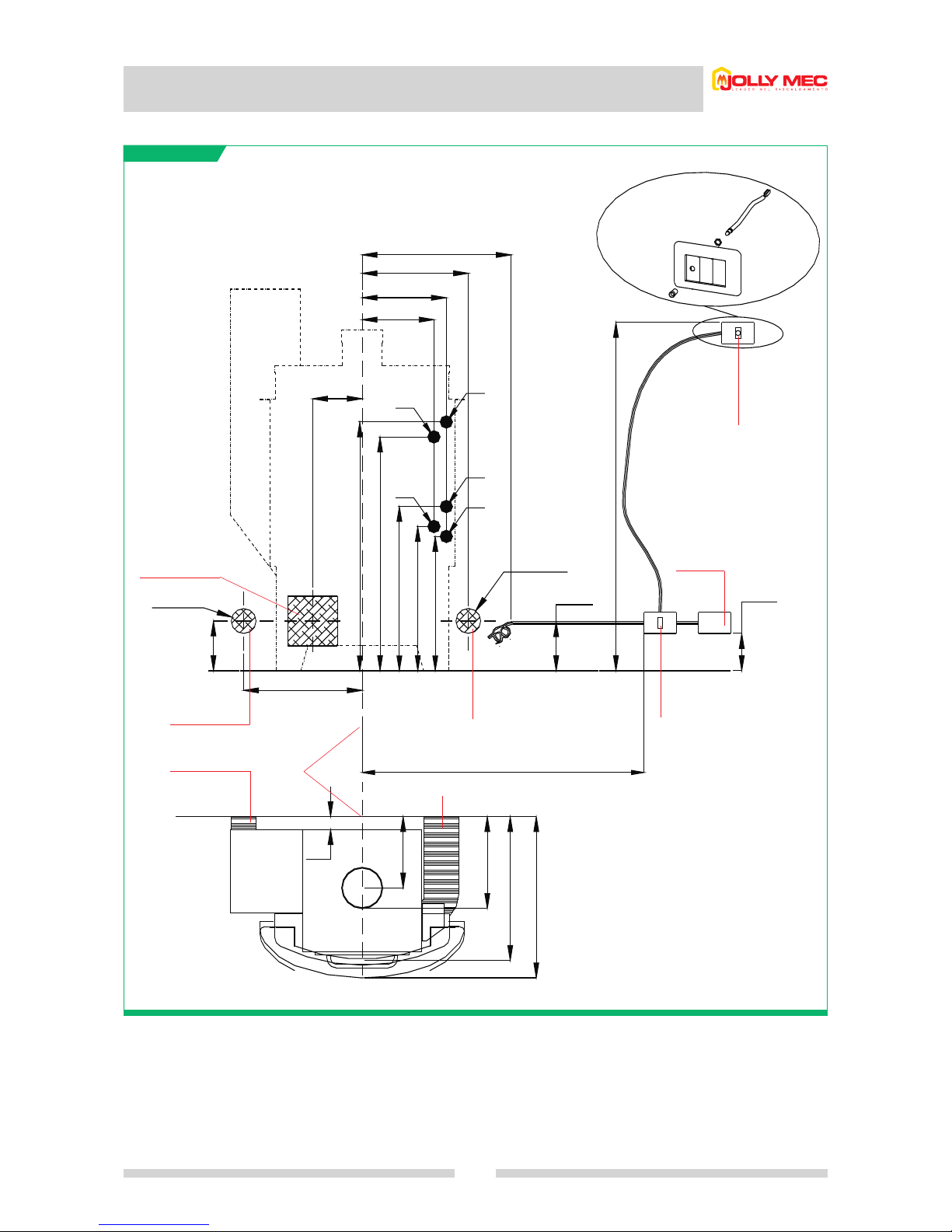
2.3 Prearrangement for electrical connections and air inlets with wall
installation
33
500
430
340
290
200
1000
940
660
580
540
Ø100
200
1400
150
480
200
Ø100
50
285
370
580
650
800
1500
b
a
d
c
e
All measurements are in millimetres (mm)
The holes for the fan and Caldo Control ducting can also be moved provided they remain inside the covering.
For firewood-pellet Foghet stoves it is mandatory to have the three doors indicated in par. 1.4 to permit loading pellets, servicing the
pellet burner and the plumbing kit.
Outside air inlet
200x200 mm
(mandatory)
Burner fan outside air
inlet (optional)
Outside air inlet for Caldo Control
(optional)
Omnipolar switch
(without bench)
(with bench)
Centre line
Outside air inlet for Caldo Control (optional)
220V 50Hz power
supply
Ambient
temperature
or ambient
thermostat
probe
a
b
c
d
e
Mains water inlet 1/2”
Pressure relief valv
e discharge 3/4”
Hot water flow 1/2”
Heating flow 3/4”
Heating return 3/4”
Page 34
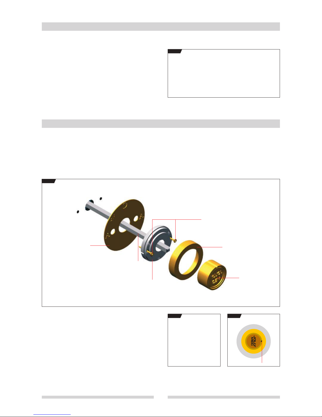
After preparing the flue and all the electrical and plumbing
connections and air intakes, as described in the previous pages,
position the stove and level it, adjusting the feet with a 19 mm
wrench (seeF
IG.1).
2.4 Adjusting the feet
FIG.1
2.5 Damper and friction unit assembly
Proceed as follows:
• Remove the gold knob from the rod by loosening the fixing grub screw with a 2.5 mm Allen key.
• Insert the rod in the hole provided in the electronic controller compartment.
• Prepare two ø 4 mm holes for the friction unit fixing screws (see F
IG.1).
• Fix the position indicator and friction unit with the two screws supplied and screw the ring (see F
IG.1).
FIG.1
Position indicator
Rod
Screws
Friction unit
Ring nut
Knob
• Fit the gold knob so that when the damper is vertical,
(i.e. open, as in F
IG.2), the Jolly-Mec logo is vertical and the
notch on the knob is aligned with A (see F
IG.3).
FIG.2
A
C
A
1
/
2
FIG.3
Notch
34
Page 35
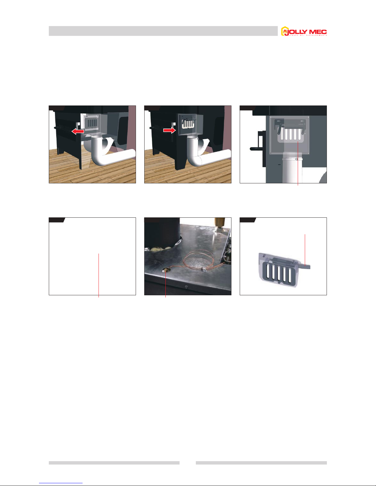
2.6 Caldo Control
35
The Caldo Control is a Jolly-Mec patented device enabling automatic adjustment of the primary combustion air according to the air
temperature read by the bulb (F
IG.5) in the boiler
This device gradually reduces the combustion air flow when the air temperature rises. The Caldo Control optimises stove fuel
consumption, thus extending burn time. The Caldo Control must only be activated in wood-burning mode (F
IG.1); during pellet mode
operation, push the lever indicated in F
IG.2all the way to close the air inlet.
The Caldo Control can be adjusted, after a settling stage, by operating the adjustment screw (F
IG.6).
FIG.1 FIG.2 FIG.3
Wood mode: pull the lever in the direction of the red
arrow (air open)
Pellet mode: push the lever all the way in the
direction of the red arrow (air closed)
Wood mode: Caldo Control grille open (with stove just
lit or in shutdown stage)
FIG.4 FIG.5 FIG.6
Wood mode: Caldo Control grille open (with stove hot) Caldo Control bulb support (on top of stove) Detail of inside of stove after removing the cast iron
grates and fire bed. Turn the adjustment screw until the
damper starts to close.
Caldo Control adjustment
screw (use an Allen key or by
hand)
Page 36
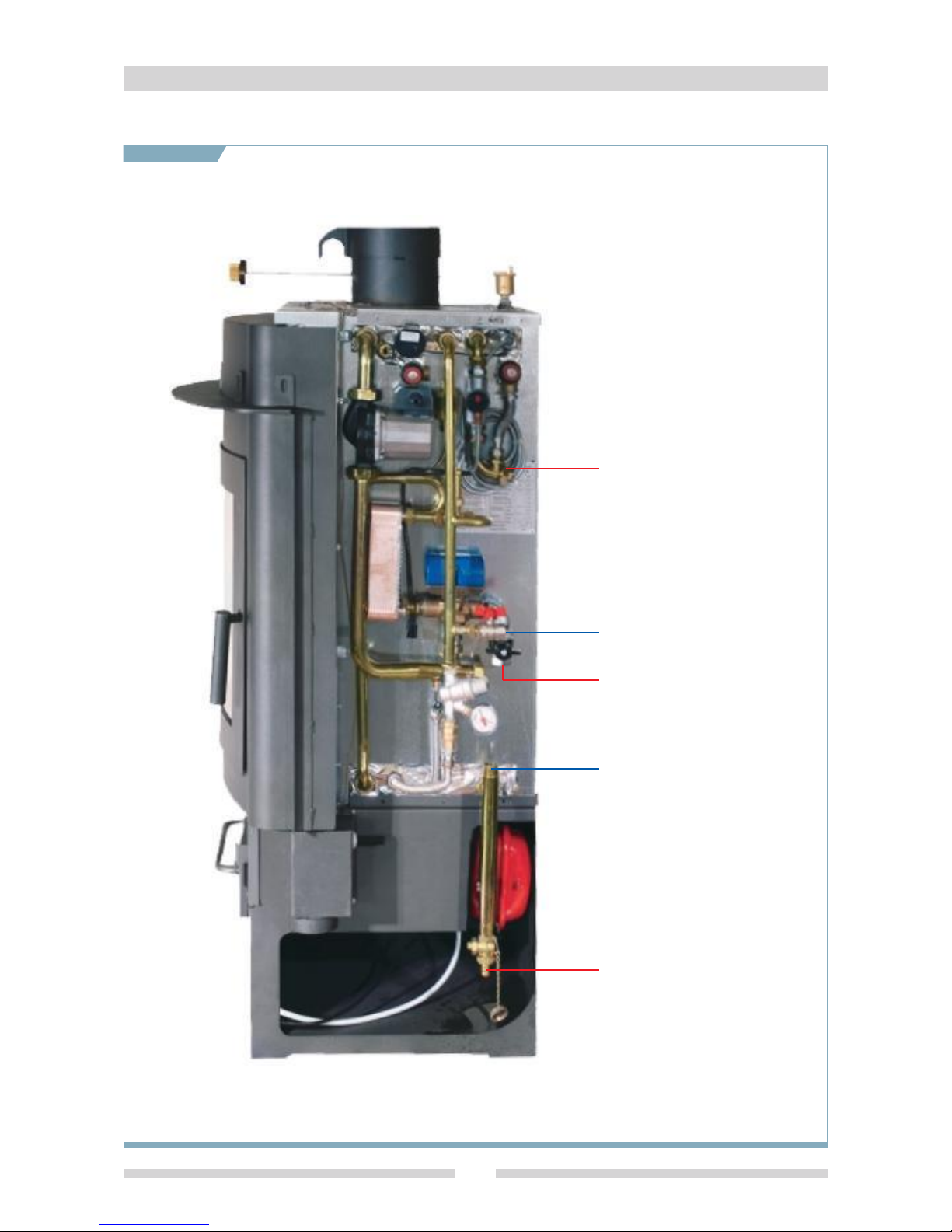
2.7 Standard hydraulic kit
36
2.7.1 With production of domestic hot water in a sealed system
Mains water inlet 1/2”
Heating system return 3/4”
Pressure relief valve
discharge 3/4”
Heating system delivery 3/4”
Boiler drain
Page 37
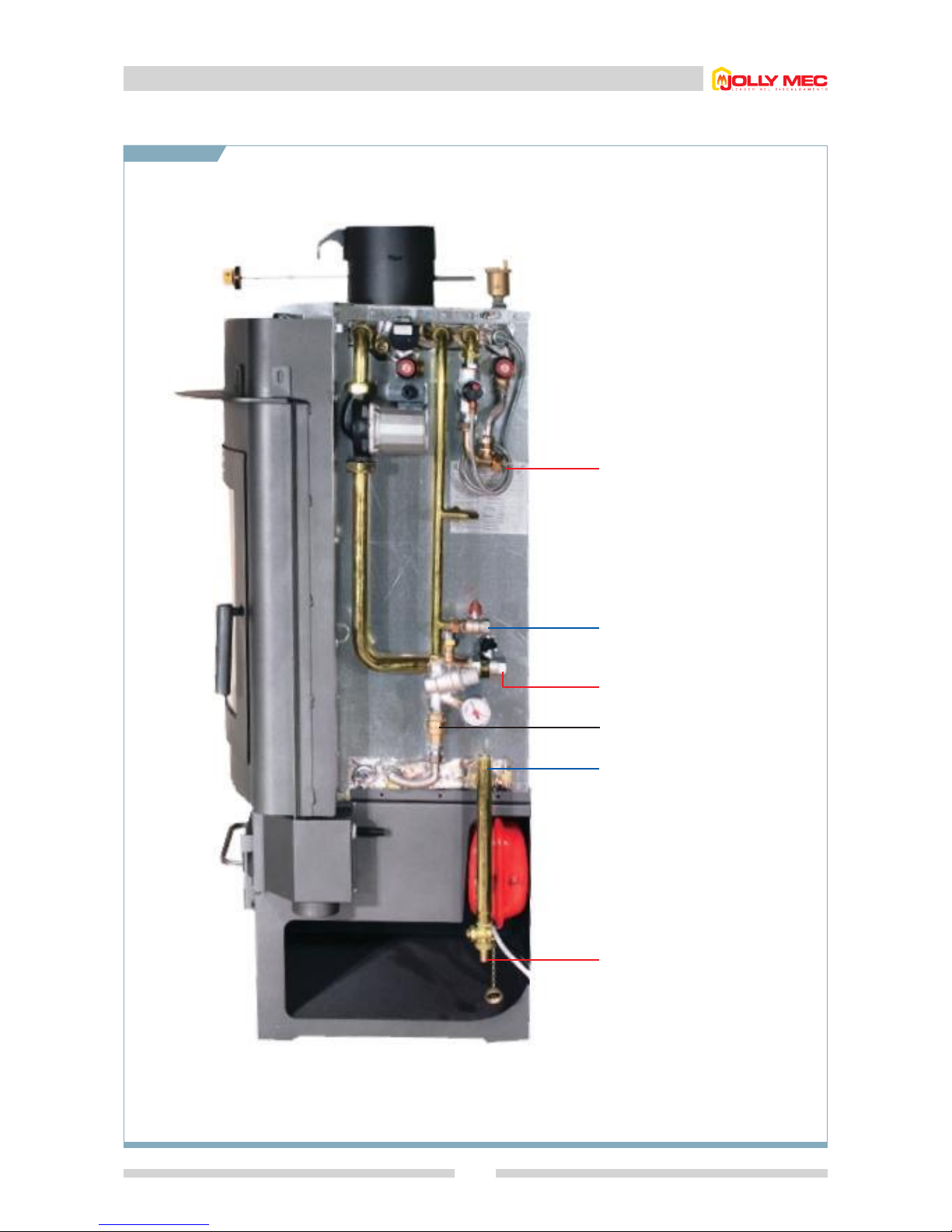
2.7 Standard hydraulic kit
37
2.7.2 Without production of domestic hot water in a sealed system
Mains water inlet 1/2”
Heating system return 3/4”
Pressure relief valve discharge 3/4”
Heating system delivery 3/4”
Boiler drain
Anti-condensation recirculation
valve (behind check valve)
Page 38
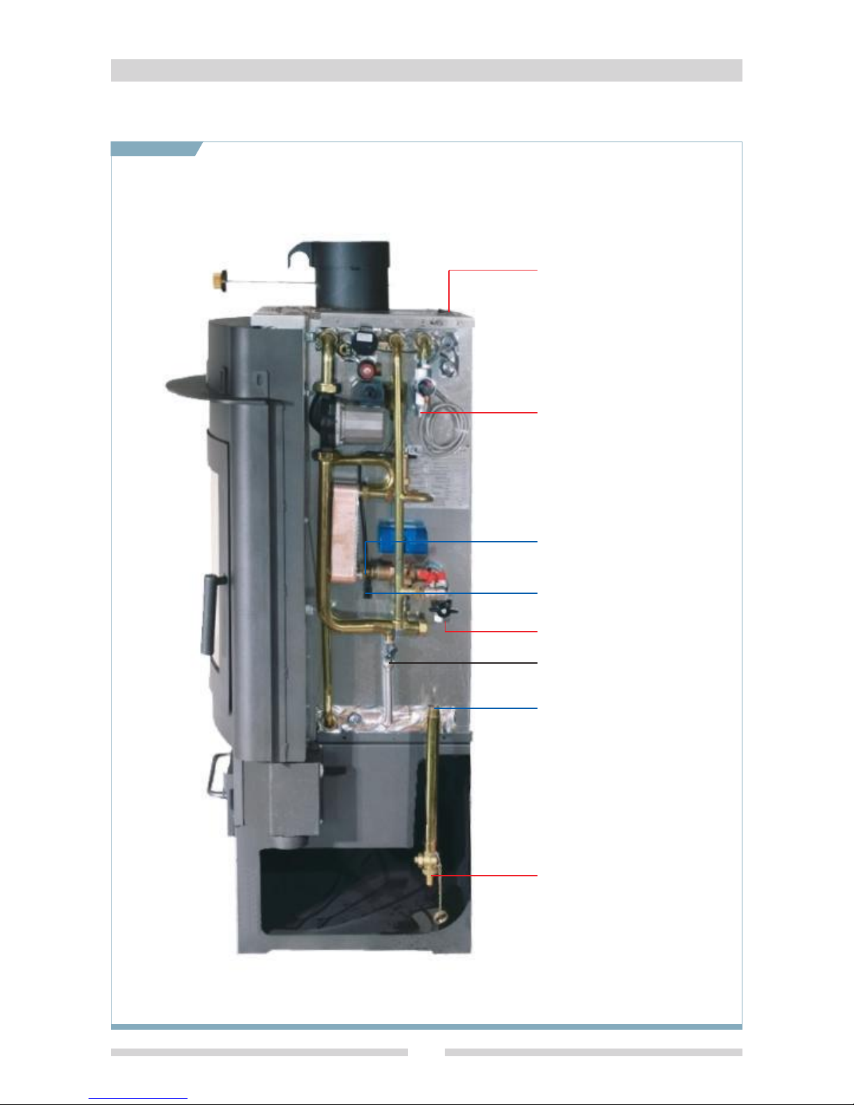
2.8 Non-standard plumbing kit
38
2.8.1 With production of domestic hot water in an open-vented system, connected to the mains water supply for
domestic hot water and boiler cooling
Hot water flow 1/2”
Mains water inlet 1/2”
Heating system return 3/4”
Temperature discharge 3/4”
To the expansion tank with float 3/4”
Heating system delivery 3/4”
Anti-condensation recirculation valve
Boiler drain
Page 39
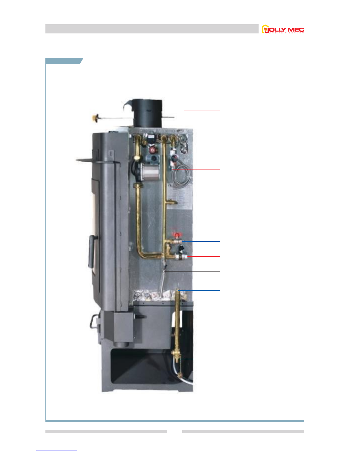
2.8 Non-standard plumbing kit
39
2.8.2 Without production of domestic hot water in an open-vented system connected to mains water supply for
boiler cooling
Mains water inlet 1/2”
Heating system return 3/4”
Pressure relief valve
discharge 3/4”
To the expansion tank with float 3/4”
Heating system delivery 3/4”
Anti-condensation recirculation valve
Boiler drain
Page 40
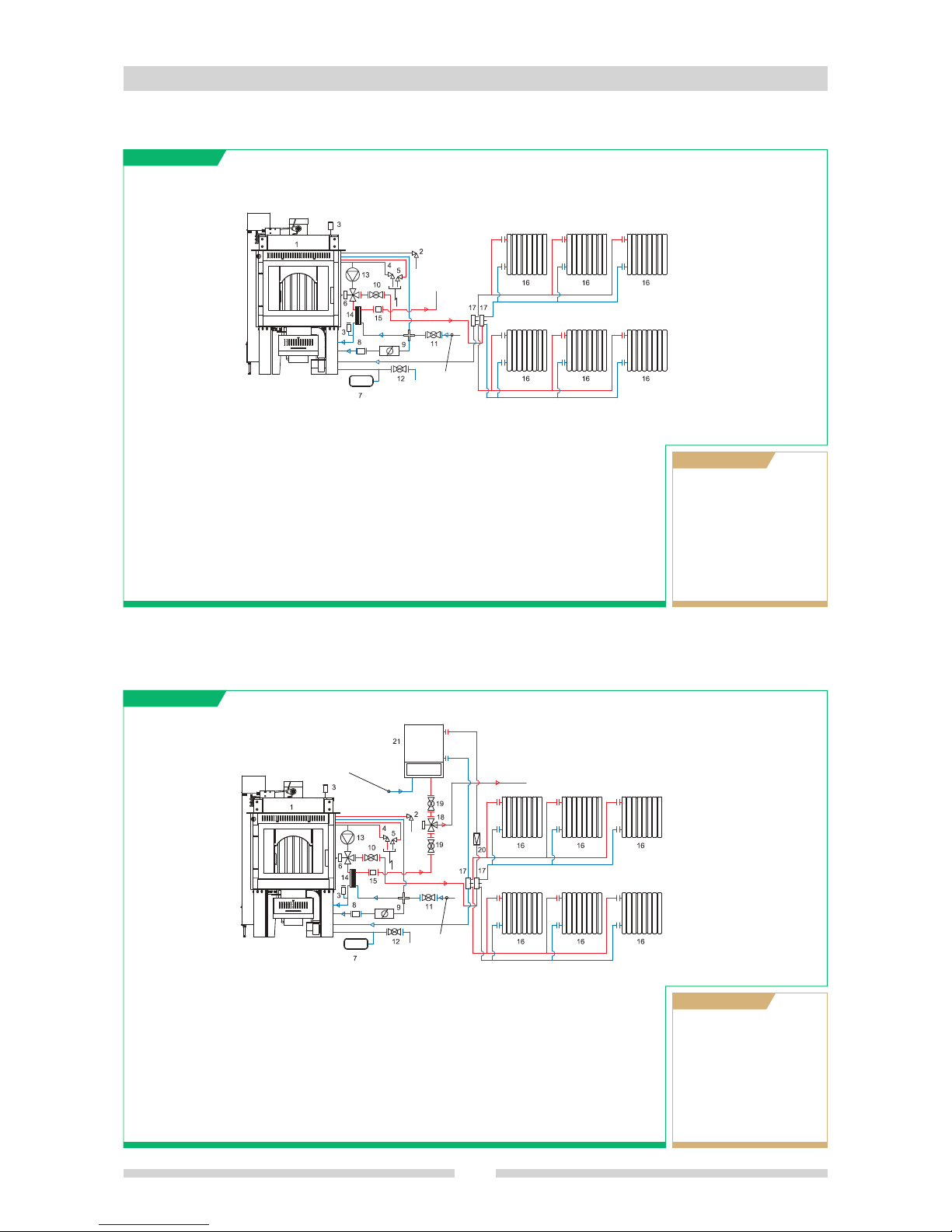
2.9 Example installations
40
2.9.1 Installation in autonomous sealed system with production of domestic hot water
A
B
C
D
E
F
FOGHET continuous flame stove
Pressure relief valve set to 3.5 atm
(supplementary valve, not to be
connected to discharge)
Vent valve
Pressure relief valve set to 2.5 atm
Temperature relief valve
Diverter valve
G
H
I
J
K
L
Expansion tank closed
Check valve
Automatic pressure reducer with
filter
Ball valve
Ball valve (mains)
Boiler drain valve
M
N
O
Circulating pump
Hot water heat exchanger
Flow switch
2.9.2 In a sealed system with production of domestic hot water, in parallel with wall-mounted boiler
A
B
C
D
E
F
FOGHET continuous flame stove
Pressure relief valve set to 3.5 atm
(supplementary valve, not to be
connected to discharge)
Vent valve
Pressure relief valve set to 2.5 atm
Temperature relief valve
Diverter valve
G
H
I
J
K
L
Expansion tank closed
Check valve
Automatic pressure reducer with
filter
Ball valve
Ball valve (mains)
Boiler drain valve
M
N
O
Circulating pump
Hot water heat exchanger
Flow switch
P
Q
R
S
T
U
Heating radiators
Manifolds
Diverter valve
Ball valve
Check valve
Wall-mounted boiler
Not included in kit
OPTIONALS
P
Q
Heating radiators
Manifolds
Not included in kit
OPTIONALS
Hot water
flow
Mains
water
inlet
Hot water
flow
Mains water
inlet
Mains water
inlet
Page 41
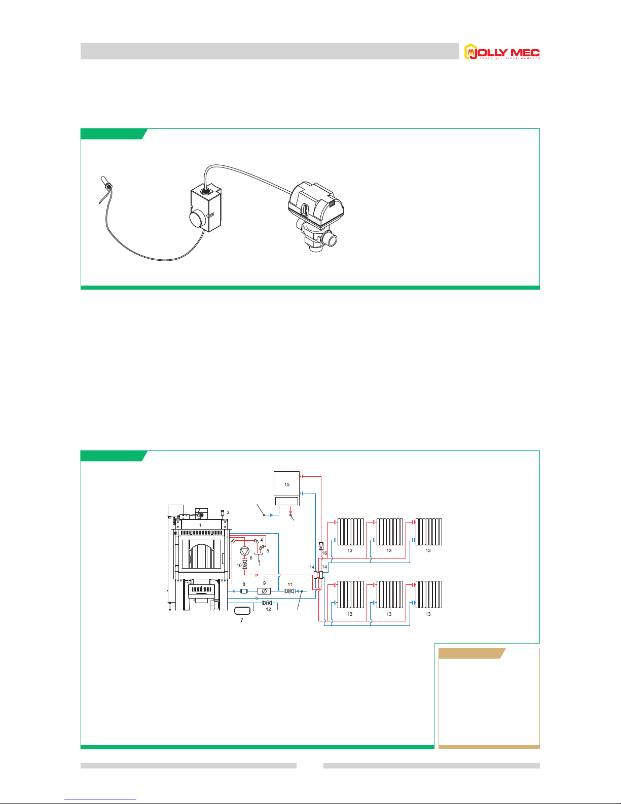
2.9 Example installations
41
2.9.3 In a sealed system without production of domestic hot water, connected in parallel with a wall-mounted boiler for
domestic hot water production
A
B
C
D
FOGHET continuous flame stove
Pressure relief valve set to 3.5 atm
(supplementary valve, not to be
connected to discharge)
Vent valve
Pressure relief valve set to 2.5 atm
E
F
G
H
I
Temperature relief valve
Circulating pump for heating system
Expansion tank closed
Check valve
Automatic pressure reducer with
filter
J
K
L
Ball type check valve
Ball valve (mains)
Boiler drain valve
M
N
O
P
Heating radiators
Manifolds
Wall-mounted boiler
Check valve
Not included in kit
OPTIONALS
Electrical wiring of diverter valve on domestic hot water flow (R), with priority given to the Jolly-Mec appliance, controlled by a
thermostat that measures the temperature in the boiler of the Jolly-Mec appliance.
A
B
R
A
B
R
Pocket inside the boiler of the Jolly-Mec appliance
with temperature probe (alternatively a bracelet
thermostat can be used fitted before the pump)
Thermostat
Diverter valve (3-way valve)
Domestic
water inlet
Mains
water inlet
Domestic
hot water
outlet
Page 42
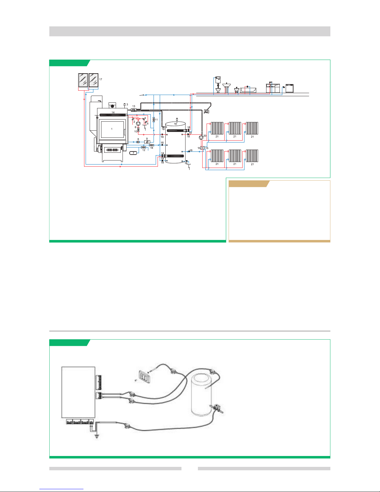
2.9 Example installations
42
2.9.4 In an autonomous sealed system with thermal cell and solar panels for radiator heating and domestic hot water
A
B
C
D
E
F
G
Combined FOGHET stove
Pressure relief valve set to 3.5 atm
(supplementary, not to be
connected to discharge)
Vent valve
Pressure relief valve set to 2.5 atm
Temperature relief valve
Circulating pump for heating system
Expansion tank closed
H
I
J
K
L
M
N
Check valve
Automatic pressure reducer with
filter
Ball type check valve
Ball valve (mains)
Boiler drain valve
Simplified electronic controller
Cooling heat exchanger
O
P
Q
R
Manifolds
Thermal cell
Solar panels
Ball valves
S
T
U
Storage cistern sensor
(optional for simplified
controller)
Circulating pump for heating
system
Heating radiators
Not included in kit
OPTIONALS
•
Simplified controller, electrical connection of thermal cell for heating and hot water
A
B
B
C
C
C
B
BB
E
K
G
J
I
D
H
F
A
B
C
D
E
F
G
H
I
J
K
Simplified electronic controller
Terminal block
Extension lead (2x1 cable)
Connection of thermal cell temperature
sensor
Thermal cell temperature sensor
Connection of the heat system circulating
pump
Circulating pump for heating system
Connection of the room temperature sensor
Room temperature probe
Room temperature sensor retainer
Thermal cell
Mains water
inlet
Room temperature probe
Page 43
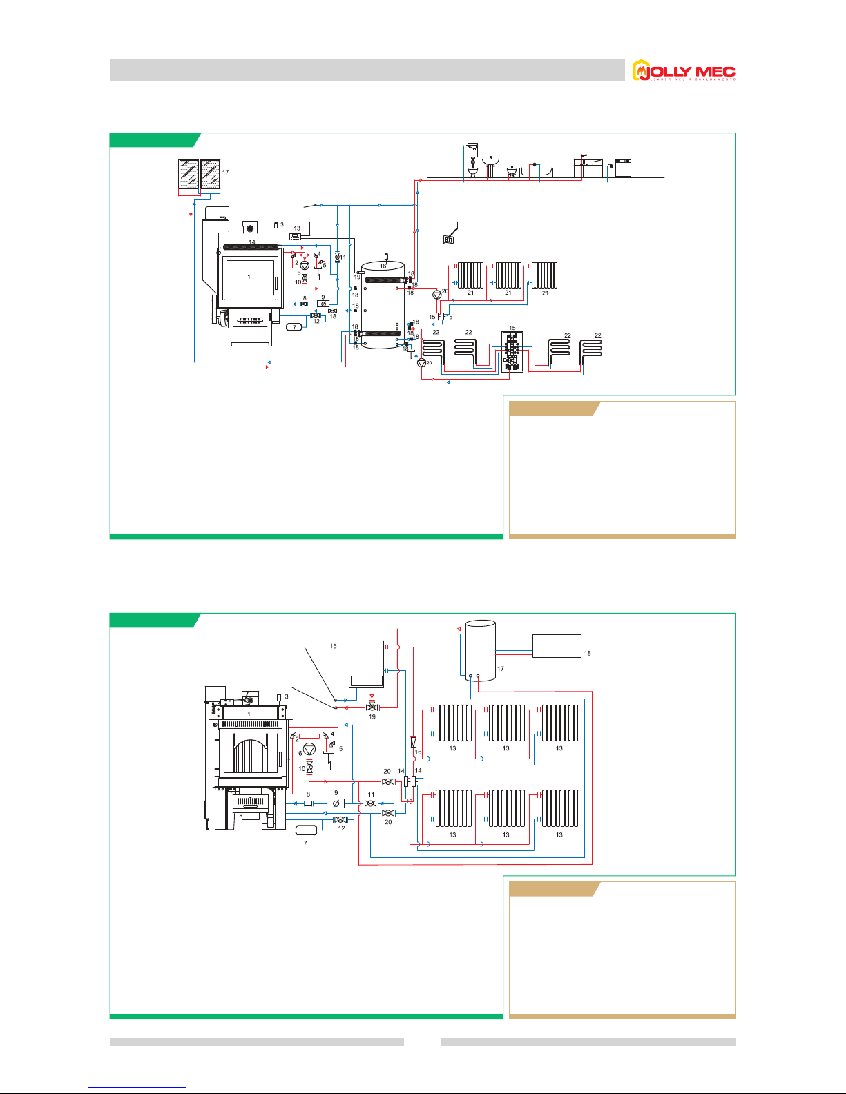
2.9 Example installations
43
2.9.5 In an autonomous sealed system with thermal cell and solar panels for production of domestic hot water
and radiator and underfloor heating
A
B
C
D
E
F
G
Combined FOGHET stove
Pressure relief valve set to 3.5 atm
(supplementary valve, not to be
connected to discharge)
Vent valve
Pressure relief valve set to 2.5 atm
Temperature relief valve
Circulating pump for heating system
Expansion tank closed
H
I
J
K
L
M
N
Check valve
Automatic pressure reducer with
filter
Ball type check valve
Ball valve (mains)
Boiler drain valve
Simplified electronic controller
Cooling heat exchanger
2.9.6 In a sealed system, without production of domestic hot water, connected in parallel to wall-mounted boiler with
domestic hot water production and solar panels with thermo boiler, hot water storage cistern
A
B
C
D
E
F
FOGHET stove
Pressure relief valve set to 3.5 atm
(supplementary valve, not to be
connected to discharge)
Vent valve
Pressure relief valve set to 2.5 atm
Temperature relief valve
Circulating pump for heating system
G
H
I
J
K
L
Expansion tank closed
Check valve
Automatic pressure reducer with
filter
Ball type check valve
Ball valve (mains)
Boiler drain valve
M
N
O
P
Heating radiators
Manifolds
Wall-mounted boiler
Check valve
Q
R
S
T
Storage cistern
Solar panels
Solenoid valve (3-way)
Ball valve
Not included in kit
OPTIONALS
O
P
Q
R
S
Manifolds
Thermal cell
Solar panels
Ball valves
Storage cistern sensor
(optional for simplified
controller)
T
U
V
Heating pumps
Heating radiators
Underfloor heating
system
Not included in kit
OPTIONALS
Mains water
inlet
Solar
panels
Room temperature probe
Domestic hot
water outlet
Domestic
water inlet
Page 44
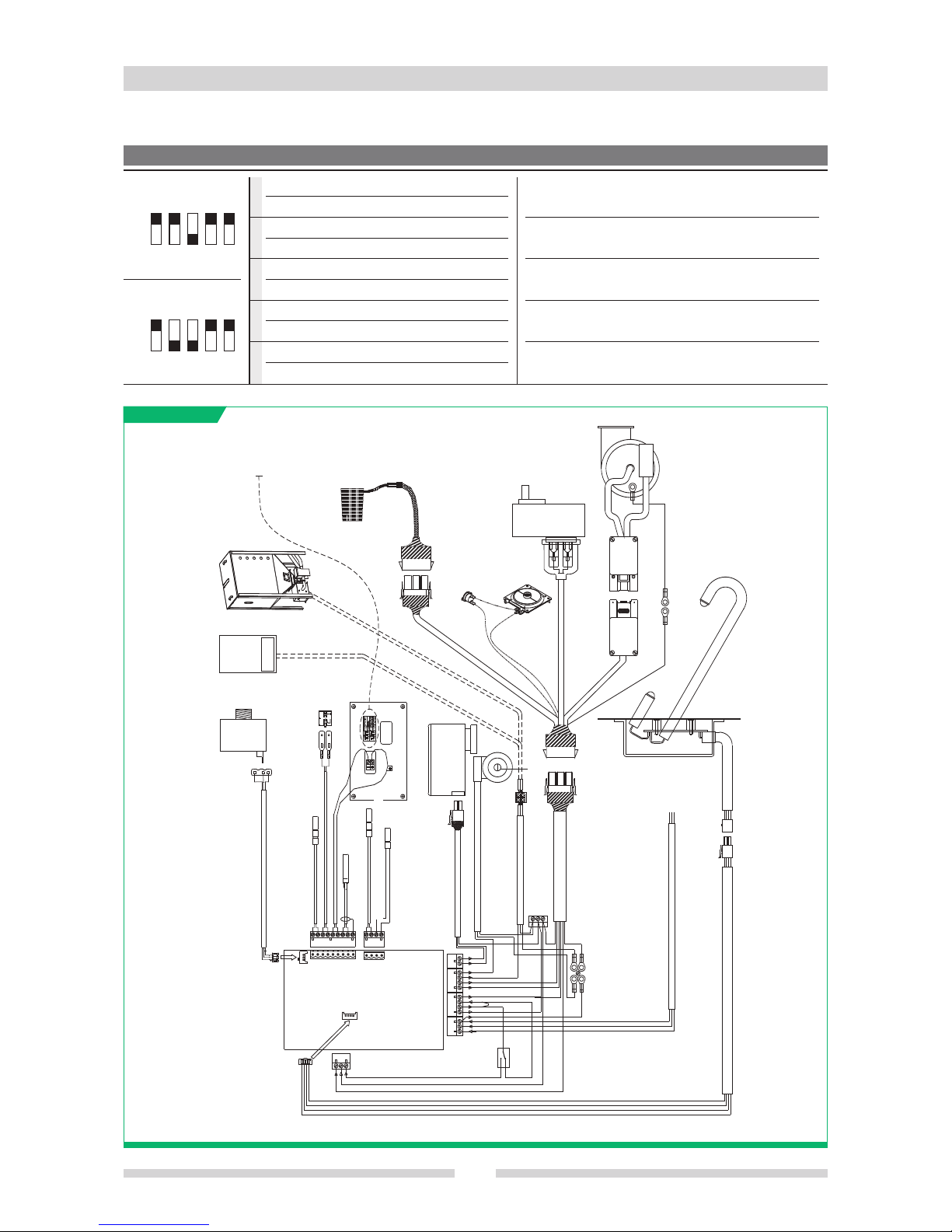
2.10 Simplified electronic controller wiring diagram
44
ON Room thermostat probe
OFF XXXXXX
ON Air heating model
OFF Water heating model
ON Relay for external boiler in parallel
OFF Relay for supplementary pellet hopper motor
ON Heating chamber (optional sensor)
OFF DHW thermoboiler (optional probe)
ON Buffer battery active
OFF Buffer battery excluded
Dip-switch 1 must always be set to ON
To control the lighting of a boiler connected in parallel, set
dip-switch 3 to ON
To control the gear motor of the supplementary pellet
hopper, set dip-switch 3 to OFF
To control the thermoboiler for hot water storage, set dip-
switch 4 to OFF
To control the heating chamber, set dip-switch 4 to ON
DIP-SWITCH POSITION
ON
OFF
12345
ON
OFF
12345
AIR
5
4
3
2
1
WATER
Water temperature probe
Domestic hot water micro
flow switch
Fume temperature probe
Room temperature probe
Domestic hot water temperature probe
Supplementary pellet hopper motor
or boiler in parallel
Terminals unit
”Ground Commutator”
Terminals unit
”Neutral Commutator”
230V 50Hz line
LOW level sensor
Remote control panel
Diverter
fan
Flue pump
Lighting
electrical element
Safety
thermostat
Pressure switch
Pellet
gear motor
Connector
Connector
Connector
Connector
Connector
Water
pressure
transducer
Combustion
air fan
Boiler in parallel or auxiliary pellet hopper
(pneumatic conveyance or auger)
WARNING: with the boiler in parallel check that the max boiler input is
less than 550W; alternatively install a relay to shut off the room
thermostat of the boiler.
Max
550W
Page 45
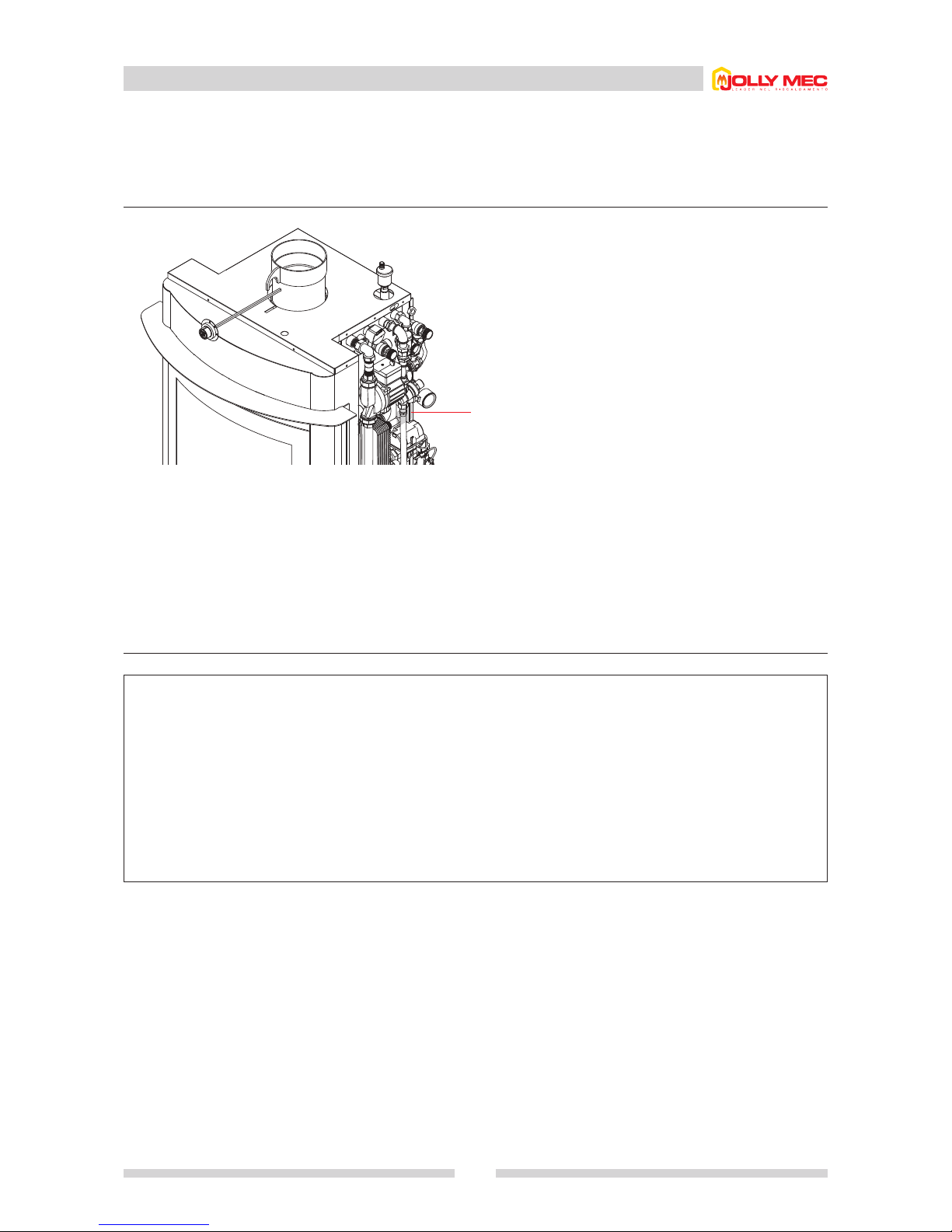
2.11 Data regarding the purchased product
45
Check that the data given in the box below correspond to that on the metal dataplate on the stove. Always give this data when requesting
assistance, replacement parts and/or work under warranty.
Plate behind kit
•
Position of dataplate on stove
•
Stamp with data relevant to the product you purchased
Page 46

46
Notes
Page 47

Page 48

SM/009-GB rev. 2 04/2008
Via Fontana, 2 - 24060 Telgate - BG - ITALY
Tel. +39 035 8359211 - Fax +39 035 833389
www.jolly-mec.it - [email protected]
 Loading...