

Page 1
U S E R M A N U A L
Professional stage lighting equipment V1.0
Page 2

Page 3

Page 4

Table of content
1.Open-Package guidelines............................................................1
1.1Package................................................................................1
2.Safety instructions......................................................................1
3.Operating determination.............................................................3
4.Rigging the fixture.......................................................................4
4.1 Mounting.................................................................................4
4.2Installing the Clamps................................................................4
4.3 Power supply connection and cut off........................................5
4.4 POWER Connection.................................................................6
4.5 DMX-512 connection/connection between fixtures.................6
Description of the device..............................................................7
5.
Dimension....................................................................................8
6.
Display control.............................................................................9
7.
Navigation in the Menu............................................................9
7.1
Display OPeration....................................................................9
7.2
Menu Maps .............................................................................11
7.3
8.DMX protocol.............................................................................12
9.Maintenance and cleaning.........................................................17
10.Electric equipment specification...............................................17
10.1 Electrical paramters............................................................17
Weight and dimensions
10.2
Channel Characteristics.......................................................17
10.3
10.4 Menu Function.....................................................................17
10.5 light table .............................................18
10.6 Gobo wheel.........................................................................20
Color wheel.....
10.7 ....................................................................21
11.Electronic drawing...................................................................23
..............................
.......................................................17
Page 5
1.Open-Package guidelines
Congra tulatio ns on ch oosing ou r prod ucts! Ple ase ca refully r ead this in stru ction man ual in its entire ty and
keep it
well for using r eferenc e. Thi s manu al contai ned about the ins tallati on and the relati ve using inform
ation of this pr o instru ction
This equ ipme nt is made of new sty le,high i nten sity plas tic.It fu lly sh ows the mod em tim es light ch arac
tic with
standa rd of DM X
Wh en r ec eive the prod uc t,ple as e be c ar eful to tak e an d pu t,check if the prod uc t ha s da mage or not be-
cause of tran spo rtation, and c hec k the f ollowing par ts:
1.Signal ca ble -1PC 2.Sa fty c abl e-1PC
3.User Manv al- 1PC 4.Ome ga ho lde r-2PCS
5.Power cab le- 1PC 5.Ser vic e car d-1PC
1.1Package
Unpacking t he fi xture
1.Open the fl igh t case cover
2.With one pe rso n on each side, li ft th e fix ture out of t he fl igh t case.
3.Unlock pa n and t ilt before ope rat ing f ixture.
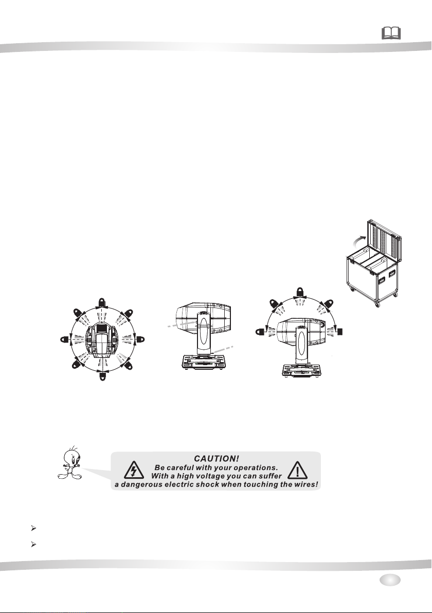
Packing the f ixt ure
1.Disconn ect t he fixture fro m pow er an d allow it to c ool .
2.lock arms a nd h as figure. (
- Fig.2-1)( Tilt M ech ani sm Lock and R ele ase ( every 45°) - Fig .2- 2)
3.Place the f ix tu re in the bottom o f the f lig ht case, an d cov er th e case without f orc ing.
ducts. Please accord ing to this manua l's relat ive when using thi s equipme nt.
terist ic wit h beauty st ruture. And it is made acc ord to CE standar d. Fully ag ree wi th the inte rnat ion
512 agre emen t.
teris-
- Fig.1
ead - Fig.2 PAN M ech anism Lock and R ele ase (every 45° )
4
°
5
45°
°
5
4
°
45
°
5
4
PAN Me chani sm Lock
45
Fig .2-1
°
k
c
o
l
ad
e
H
LOC KED UNL OCKED
45°
Lev el vert ical tr anspo rtati on lock F ig.2
ck
ck
o
o
m l
m l
Ar
Ar
5
4
°
5
4
PAN Me chani sm Lock
°
4
Fig .2- 2
5
°
Avi ation b ox
Fig .1
2.Safety instructions
Every perso n inv olvd with inst all ati on and mainten anc e of this device t o:
-Be qualilf ied
-Follow the i nst ructions of th is ma nua lentert ain men t theater,per for ming and palyi ng ha ll et c.
This dev ice has lef t our pr emi ses in a bsolute ly perfec t conditi on. In ord er to maint ain this co ndition a nd toensure a s afe opera tion ,it is absol ute ly nec ess ary fo r the user to f ollow the s afety ins tructio ns and warn ing
notes wr itten in th is manual .
Important:
The m anufact urer will n ot accept l iabilit y for any res ulting da mages cau sed by the nonobs erv ance of this
manual o r any unaut horized m odifica tion to the d evice.
Please c onsider t hat damag es caused b y manu al modifi cat ions to the devic e are not sub ject to war ranty.
1
Page 6

Never let the p owe r-cord come in to co nta ct with oth er ca ble s! Handle the po wer c ord and all conn ect ion s
with partic ula r caution!
Make sure tha t the a vailable vol tag e is no t higher th an st ate d on the rearpan el.
A lways plug in the pow er pl ug least. Make s uer t hat t he power- swi tch i s set to off- pos ition before y ou co n
ections wit h the mains with par tic ula r caution !
Make sure tha t the p ower-cord is n eve r cri mped or dam age d by sh arp edges.Ch eck t he decice and th e power-cord f rom t ime to time.
Always disco nne ct from the main s, wh en th e device is n ot in u se or b efore cleani ng it .
Only ha ndl e the power-co rd by t he plug,Neve r pul l out t he plug by tu ggi ng th e powercord.
Thi s devi ce fa lls u nder protect ion c lass I.There for e it is essentia l to co nne ct the yellow/ gre en conductor
to earth.
Th e elect ric c onn ection,rep air s and servicin g mus t be ca rried out b y a qua lif ids employee .
Do not co nne ct this device t o a dim mer pack.
Do not sw itc h the fixture on a nd off in short in ter vals as this wou ld re duce the lamp’s li fe.rly mean that the
device is def ect ive.
Do not touch th e dev ice’s hou sin g bare hands dur ing i ts op eration (ho usi ng becomes hot )!
For replace men t use lamps and fu ses o f sam e type and ra tin g onl y.
Caution! e yeb ama ges !
Avoid look ing d ire ctl y int o the l igh t source(meant especially for epilept ics )!
470 W
t 40a°C
Minimum di sta nce o f ill umi nat ed objects
18
The project or ne eds to be positi one d so th at the obje cts h it by t he beam of light a re at l east
18 metres fro m the l ens of the proje cto r.
Maximum am bie nt te mpe rat ure
Do not operat e the f ixture if the am bie nt te mperatu er( Ta) e xce eds 4 0°C (104°F).
Temperatur e of th e ext ern al su rfa ce
t 80c°C
The maximum t emp erature that c an be r eac hed on the ex ter nal s urface of the fi tti ng,in a thermally stead yst ate,is 8 0°C ( 176°F).
IP20 prote cti on ra tin g
IP20
The fitting i s pro tected again st pe net ration by s oli d of ov er 12mm (0 .47”) in diameter ( fir st
digit 2), but n ot ag ainst drippi ng wa ter, rain,splas hes o r jets of water (s eco nd digit 0).
Indoor use o nly
Risk Gr oup 1
Accor ding to
En624 71
F
2
Not suitab le fo r hou seh old i llu mination
Photobio log ica l Saf ety
CAUTION. Do n ot lo ok direct ly at t he li ght sourc e.D o not look at the li ght b eam with optic al de vices or any ot her t ool that co uld c aus e light con ver gence.
The fixture m ust b e positio ned s o tha t the minim um di stance betwe en th e front lens and h uma n
eye is at least 3 met res to prev ent p ers onal phot obi ological ris ks.
Mounting s urf ace s
It is permiss ibl e to mount th e fit tin g on normal ly fl ammable surf ace s.
The produc ts to w hic h thi s man ual r efe rs comply with the European Directiv es pu rsuant to:
•2006/95/E C - Saf ety of electri cal e qui pment sup pli ed at l ow voltage (LVD)
•2004/108/ EC - El ectromagne tic C omp atibili ty (E MC)
•2011/65 /EU - R estriction o f the u se of certain ha zar dous substan ces ( RoH S)
•2009/125/ EC - Ec oDesign requ ire men ts for Ener gy- rel ated Product s (Er P)
Protecti on ag ain st el ect ric al sh ock
Connectio n mus t be made to a power s upp ly sy stem fitt ed wi th effici ent e art hing (Class I ap pliance acco rdi ng to standard E N 605 98- 1) .It i s, moreover, recomme nde d to protect the s upp ly
Page 7

lines of t he projec tors from i ndirect c ontact an d/or sho rtin g to ea rth by u sin g appr opr iate ly si zed
residu al curren t devices .
Disposing
This pro duct is sup plied in co mplianc e with Euro pean Dire ctiv e 201 2/19 /EU -Waste Ele ctrical a nd
Electr onic Equi pment (WE EE) . To pre serv e the e nvir onm ent pl eas e disp ose /rec ycd e this pro duct a t
the end of i ts life acc ording to t he local re gulatio n.
Battery
This pro duct cont ains a rech argeabl e lead-ac id or lithi um iro n tet raph osp hate b att ery.To pr eserve th e
enviro nment,p lease dis pose the ba ttery at th e end of its li fe acc ord ing to t he re gula tio n in for ce.
Lamp
E
!
The fitt ing mount s a high-pr essure la mp that nee ds an exter nal ig nit er. Thi s igniter i s fitted on to the
appara tus. -Car efully re ad the "ope rating in structi ons" p rov ided b y the l amp ma nuf actu rer.
-Immed iately re place the l amp if dama ged or defo rmed by hea t.
Maintenan ce
Before s tarting a ny mainte nance wor k or cleani ng the proj ecto r,cu t off po wer from th e mains sup ply.
After sw itching o ff, do n ot remove a ny parts of t he fittin g for at leas t 10 minute s. After thi s time the li ke
lihood o f the lamp ex ploding i s virtual ly small. If it is nece ssar y to re plac e the l amp, wai t for an oth er 15
minute s to avoid ge tting bur nt.The fi tting is de sign ed to h old in a ny sp lint ers p rodu ced b y a lamp e xpl oding.
3.Operating determinations
This dev ice is a movi ng-head f or creati ng decora tive effects an d was deaig ned for ind oor use onl y.
If the dev ice ha been e xposed to d rastic te mperatu re flu ctu atio n(e .g.a fte r tran spo rtat ion ).do not weitc h it on im mediate ly.Th e ari sing c ondensa tion wate r might dam age your de vice,Le ave the dev ice switc hed of f until it ha s reached roo m tempera ture.
Never ru n the devic e without l amp!
Do not sha ke the devi ce,Avoid brut e force whe n install ing or oper ating the d evice.
Never li fe the fixt ure by hold ing it at the p rojecto rhead, as t he mec han ics ma y be da mage d. Alw ays ho ld th e fixt ure at the tr ansport h andles.
When cho osing the i nstalla tion-sp ot,plea se make sur e that t he de vice i s not e xpos ed to h eat, moi stur e or du st.T here shou ld not be any c ables lyi ng around .You en dang er yo ur own a nd th e safe ty of o ther s!
The mini mum dista nce betwe en light ou tput and th e illumin ated s urf ace mu st be m ore th an 0. 2 mete rs.
Make sur e that the ar ea below th e install ation pla ce is block ed whe n rig ging ,de rigg ing o r serv ici ng the f ixt ure.
Always f ix the fixt ure with an a ppropri ate safet y rope , Fix t he saf ety r ope at t he co rrec t hol es onl y.
Operat e the fixtu re after ha ving chec ked that th e hous ing i s firm ly cl osed a nd al l scre ws ar e tigh tly f aste nd.
The lamp m ust never b e ignited i f the objec tive-le ns or any hou sing -co ver is o pen , as dis cha rge la mps m ay explose an d emit a hign u ltravio let radia t, which ma y cause bur ns.
The maxi mum ambie nt temper ature 40°C mu st never be e xceeded .
Operat e the devic e only afte r having fa miliari zed with it s func tio ns. Do n ot pe rmit o per atio n by pe rsons not qu alified f or operat ing the dev ice. Most d amages ar e the resul t of unp rof essi ona l oper ati on!
Please u se the orig inal pack aging if th e device is t o be transp orte d.
Please c onsider t hat unaut horized m odifica tions on th e devi ce ar e forb idd en due t o saf ety re aso nsl.
If this de vice will b e operate d in any way di ffer ent to the on e describ ed in this ma nual, the pro duct may suff er
damage s and the gua rantee be comes voi d.Furth ermore, a ny oth er op erat ion m ay lea d to da nger s lik e shor t-c ircuit,bu rns, elec tric shic t,burns d ue to ultra viol et ra diat ion ,lam p exp losi on, cras h etc .
3
Page 8
4.Rigging the fixture
4.1 Mounting
Pay attenti on to t he re gul ations of CE.
Installation b y qua lif ied staff to comple te.
For the vario us mo unting posit ion s of th e FIXTURE (st and ing on the floor, s ide ways or hangin g di fferent
accessori es ki ts are availab le.
Through thi s a saf e and firm insta lla tio n is assure d.
You’ ll fi nd specia l con nec tors on the bott om si de of the system w hic h are put to use her e.
4. 2 Installing the Clamps
Please cons ide r the respecti ve na tio nal norm s du rin g the I nstallatio n!T he installat ion m ust o nly be carried out by an au tho rized dealer !
The install ati on of the projec tor h as to b e built and c ons tru cted in a way that i t can h old 10 times the w eight for 1 hour wi tho ut any harming d efo rma tion.
The install ati on must always b e sec ure d with a seco nda ry sa fety attachm ent , e.g.an appro pri ate catch
net.This se con dary safety at tac hme nt must be co nst ruc ted in a way that no p art o f the installa tio n can
fall if the mai n att achment fail s.
When servic ing t he fixture sta yin g in th e area belo w the i nst allation pla ce, on bridges,u nde r hig h working
places and ot her e ndangered ar eas i s for bidden.
The operato r has t o make sure that s afe ty- relatin g and m ach ine-techni cal i nstallatio ns ar e app roved by
an expert bef ore t aking into ope rat ion f or the firs t tim e and a fter changes b efo re taking into o per ati on another time.
The operato r has t o make sure that s afe ty- relatin g and m ach ine-techni cal i nstallatio ns ar e app roved by
an expert aft er ev ery four year in t he co urs e of an accep tan ce te st.
The operato r has t o make sure that s afe ty- relatin g and m ach ine-techni cal i nstallatio ns ar e app roved by
a skilled per son o nce a year.
The project or sh ould be instal led o uts ide areas wher e per sons m ay walk by or b e sea ted.
Important !Ov erhead riggi ng re qui res exten siv e exp ering CE,in cluding (bu t not l imited to) calculatin g
working loa d lim its, install ati on ma terial being u sed , and periodic s afe ty inspectio n of al l ins tallation ma terial and th e pro jector. If you la ck th ese q ualific ati ons , do not attempt t he in stallation y our sel f, but inst ead use a profes sio nal structur al ri gge r. Imprope r ins tal lation can res ult i n bodilyinju ry an d or da mage to
property.
The project or ha s to be installe d out o f the r each of peo ple .
If the projec tor s hall be lowere d fro m the c eiling or h igh j ois ts, professi ona l trussing sys tem s h ave
to be used. The p rojector mus t nev er be fixed swin gin g fre ely in the ro om .
Caution Pro jec tors may cause s eve re in juries wh en cr ash ing down! If you h ave d oubts concer nin g the
safety of a pos sib le installat ion , do no t install t he pr oje ctor!
Before rigg ing m ake sure that th e ins tal lation ar ea ca n hol d a minim um point l oad o f 10 times the
projector s w eig ht.
4
Page 9
The project or ca n be placed dire ctl y on th e stage floor or r igg ed in any orient ati on on a truss withou t alt ering its oper ati on character ist ics .
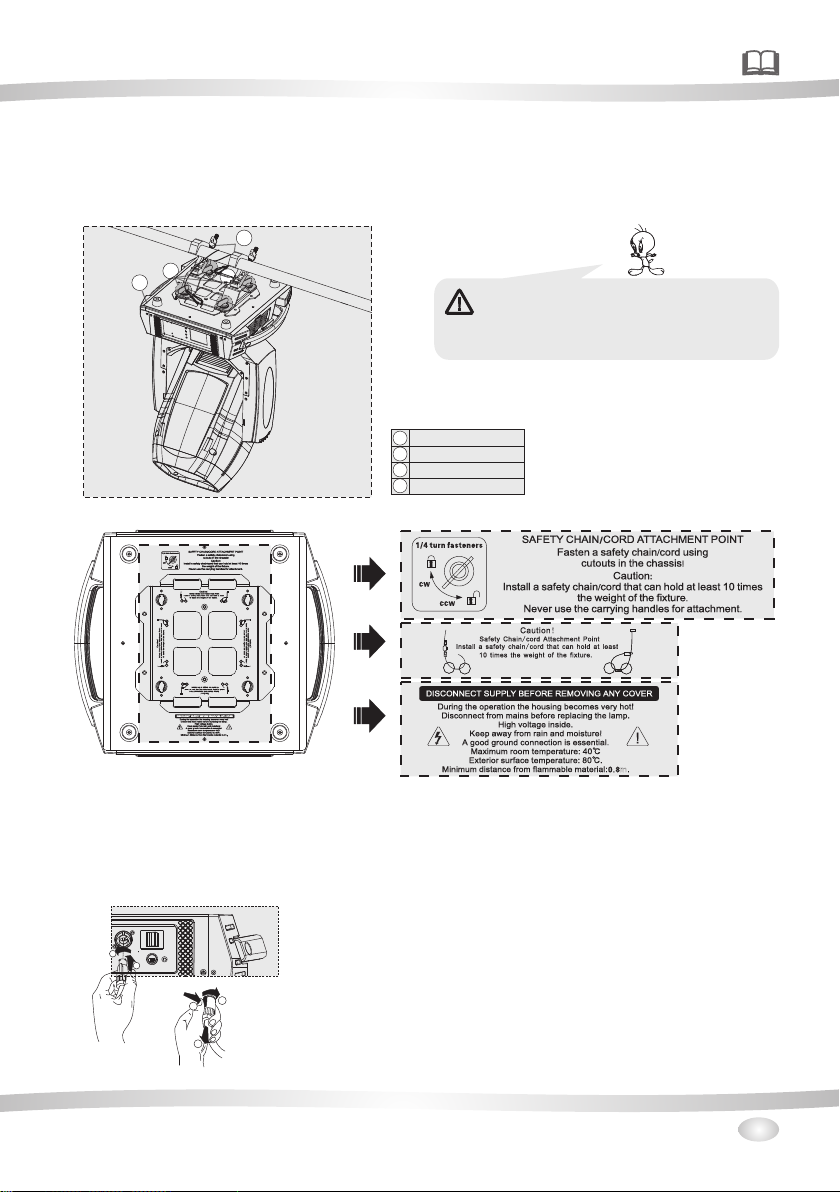
For overhea d use ,always inst all a s afe ty-rope that c an ho ld at least 10 tim es th e wei ght of the fixtu re.You
must only use s afe ty-ropes wit h scr ew on c arabines.P ull t he safety-ro pe th rou gh th e two ape rtu res on th e
bottom of the b ase a nd over the trus sin g sys tem etc.
2
1
4
3
Warning: it i s nec essary to make s ure t hat
the install ati on lo cation is p erf ect ly appropria te,
and the insta lla tio n locatio n is sa fe an d reliable.
Lock catch
1
omega holde r
2
secure chai n
3
mounting pl ate
4
4.3 Power supply connection and cut off
Connect the l igh t source to the ma in po wer s ource with the p lug o f the power cord , or cu t off the pow er
supply:
Connectio n: ac cording to pro ced ure s, the power plu g and s ocket is inser ted i nto t he groove one on e
alignment , rot ation.
Cut off: a cco rding to proce dur es, press the bu tto n on th e rotating plu g, pu ll out.
2
1
2
1
3
5
Page 10

4.4 Power Connection
If you wish to ch ang e the power supp ly se tti ngs, see th e cha pte r appendix Con nec t the fixture to t he
mains with th e enc losed power ca ble a nd pl ug.
Warning: pl eas e ver ify the pow er of t he po wer
supply equi pme nt prior to the co nne cti on! Earth w ire
must be groun ded !
CABLE(EU) CABLE(US)
Brown Black Live
Light blue
White Neutral
Yell ow/ Green Green
Pin
Earth
INTERNATIO NAL
L
N
4.5 DMX-512 connection/connection between fixtures
Only use ster eo sh ieded cable an d 3-p in XL R-plugs and co nne ctors in order t o con nect.
DMX512DMX512
Caution
At the last fix tur e,the DMX-ca ble h as to b e termina ted w ith a t erminatou. s old er a 120 resisto r bet ween
signal(-) a nd Si gnal (+) into a 3- pin X LR- plug and plug it i n the D MX-output of t he la st fixture.
DMX output
3-pin XLR soc ket
2 1
3
DMX iutput
3-pin XLR soc ket
2 1
2 1
3
3
1: Gro und
2: Sig nal (- )
3: Sig nal (+ )
DMX output
5-pin XLR soc ket
5 1
5 1
4 2
4 2
3
3
DMX iutput
5-pin XLR soc ket
5 1
5 1
4 2
4 2
3
3
1: Gro und
2: Sig nal (- )
3: Sig nal (+ )
4: N. A.
5: N. A.
6
Page 11

DMX Terminator Diagram
-For instal lat ions where the D MX ca ble h as to run a lon g dis tan ce or
is In an electr ica lly noisy envi ron men t it is recom men ded t o use a
DMX termina tor. This help in p rev enting corru pti on of t he signal b y
electrica l noi se. The DMX t erm inato r is simpl y an XL R plug witha
120 res ist or connected b etw een pins 2 and pin s3, w hic h is then
Ω
plugged int o a the o utput XLR sock et of t he la st ifxtur e in th e cha in.
5.Description of the device
1
2
3
2
DESIGN CONSTITUTION
1.Head
2.Arm
3.Base
1
3
120Ω
PIN2
PIN3
CINTROL PANEL
. - pin X LR fe mal e
4 3
.
5 Power-in
.Powe r swi tch
6
.
7 5- pin X LR fe male
. nsuranc e sea t
8 I
. - pin X LR ma le
9 3
10.5
-pin XL R mal e
13
11
14
12
15
16
4
5
7
6
10
9
BACK PANEL
11.
Status indi cat or lamp
12.ENTER bu tto n
13.Touch scre en( LCD display)
14.MODE but ton
15.UP bu tto n
16.DOWN but ton
8
7
Page 12

17
17.WDMX wir e
6.Dimension
8
Page 13

7.Display control
7.1 Navigation in the Menu
Using the but ton s or touch scree n, an d thi s can be simp ly an d eas ily set the addr ess c ode and
code.
If you view or mo dif y the lighting f eat ure s et, then press E NTE R button, the di spl ay wi ll enter th e men u
interface . Bot h there is sub men u cor res ponding to the f unc tional opera tio n of the main menu . Eac h of th e
menus is repr ese ntative of the s pec ifi c features of th e lam p. The specifi c con tents shows as t he ta ble
menu below.
Set or browse l igh ting functio n, pr ess U P or DOW N but ton.
Press ENTER t o sav e your changes o r ent er th e submenu .Pr ess t he UP or D OWN c an ch ange the numerical (incr eas e or decrease in v alu e).
Press the MOD E but ton to return to m enu . Set a time 0 to 10 min ute s aut omatically e xit m enu interfac e
and close the s cre en.
7.2 Display Operation
Put through p owe r supply, op en th e power switch o f lam ps and lantern s, di spl ay show the comp any
LOGO
website. Acc ord ing to the main in ter fac e, as shown i n fig ure :
In the main int erf ace, press "MO DE" b utton to view th e sof twa re version, pr ess t he "UP" "DOWN" c an modify the DMX a ddr ess.
If the screen " " i con i s green,said D MX si gnal connect ion i s nor mal, this stat e can b e used to check th elamps and la nte rns and connec tio n bet ween the contr ol ta ble is normal.
Fix ture ID
00 10
E1 2:B usEr r1 01
E1 5:B alla st Er ror 0 7
E1 7:B D1 BUS E rro r 99
E1 8:B D2 BUS E rro r 99
E1 9:B D3 BUS E rro r 99
Mode Ente rUp Down
00 1-0 21Se tti ng s
1
1
A
Lam p Contr ol
ON
OFF
Con firm
Mode Ente rUp Down Mode Ente rUp DownMode Ente rUp Down
001
Mai n inter face
001
Main interface
Cha nnel Mo de
Mod e1 1-34
Mod e2 1-30
Mod e3 1-34
1
Mode Ente rUp Down
P
1
Dmx I nput
Dmx I nput
Wir ed Inpu t
Wir eless I nput
Wir eless I n/
XLR o ut
his
t
s
if
s
d
e
o
r
m
o
t
s
d
n
.
o
s
c
s
e
e
s
r
d
2
d
Dmx A ddres s
r
a
o
f
X
a
M
e
r
D
a
e
h
t
y
0 10
Mode Ente rUp Down
functions
Can vi ew the co mpany L OGO,w eb
site , hardw are, so ftwar e versi on, dat e.
Settings
Set U p
Inf oramt ion
Per sonal ity
Man ual Con trol
Adv anced
Mode Ente rUp Down
001-02 0
PAN
CH-001: 000 .0% 000
CH-002:PAN Fine 000.0% 000
CH-003:Tilt 000.0% 000
CH-004:Tilt Fine 000.0% 000
CH-005:Cyan 000.0% 000
CH-006:Magenta 000.0% 000
CH-007:Yellow 000.0% 000
Mode Ente rUp Down
menu int erface
This lamp can b e set t o turn off th e aut omatic flip sc ree n function, to uch t his " “ i con can be ma nua lly
flip screen .
9
Page 14

Click on the ma in in terface of the i con , num erical to v iew v iew S ettings rela ted i nformation o f lam ps and
lanterns. Sym bols such as the m ain i nte rface app ear “ “ ,th e following er ror m essage indic ate s that there
might be a lamp s and l anterns,ca n cli ck to v iew and con tro l inf ormation con ten t to modify the la mps a nd
lanterns.
CODE
ERRO INFO CHECK MEASURMENT NOTE
E01 SpiFlashError Check the welding of memory IC
E02 Program Err 1 Check the welding of Chip
E03 Program Err 2 Check the welding of master IC EP3C
E04 MBDInit Error
E05 BD1Init Error
E06 BD2Init Error
E07 BD3Init Error
E12 BusErr1
E13 BusErr2
E14 SPDError Check the welding of master IC
E16 MFpga Error
E17 BD1 BUS Error
E18 BD2 BUS Error
E19 BD3 BUS Error
E21 Pan FB. Err
E23 Tilt FB. Err
E22 Pan Zero Err
E24 Tilt Zero Err
E25 Prism Err1
E26 Prism Err2
E27 Prism RtErr1
E28 Prism RtErr2
E29 R.Gobo Err1
E30 R.Gobo Err2
E31 Zomm Err
E32 Focus Err
E33 St.Gobo Err
E34 Cyan Err
E35 Magenta Err
E36 Yellow Err
E37 B.Fan1 Error
E38 B.Fan2 Error
E39 B.Fan3 Error
E40 L.Fan1 Error
E41 L.Fan2 Error
E42 L.Fan3 Error
E43 L.Fan4 Error
E44 GOBO Fan Error Check the fan of head GOBO
Check the communication signal 485& 485 chip & memory IC
Check main cable ABAB(485) chip
Check the communication signal& welding of communication
chip
Check the light coupling line, optical coupling switch and a
plate of the relative position measurement
Check cable of sensor, distance and location of ,magnets and
sensor
Check the fan of head
Check if the fan(80) of the lamp holder is working
Check if the blowing machine of lamp holder is working
RESET
ERROR
10
Page 15

7.3 Unit Menu
Dmx Address 001~XXX Dmx Address
Set up Channel Mode default Mode1
Fixture Id 0001~9999 Lamps address
Fixture Times XXXXX h XX m Total working hours
Lamp Times
Information
Personality
Manual
Control
Advanced
Error List Error details
Diagnosis Diagnosis
Fans Monitor Fans Monitor
DMX Values DMX Values
Lamp
Pan/Tilt
Dmx Input
BlackOut
Screen
Language
Lamp
Reset
Channel Chanel Testing
Calibration lnput Password XXXX Chanel Adgusting
Factory Default ON/OFF Reset to orignal parameters
Touch Calibration Touch screen adjusting
Mode1 1~34
Mode2 1~30
Mode3 1~34
Lamp On Times XXXXh XXm Lamp On working hours
Lamp Strike XXXX Lamp Strike
Reset Lamp Time Reset Lamp Time
BOARD 1: XX.XX%
BOARD 2: XX.XX%
BOARD 3: XX.XX%
Power ON Light ON/OFF Power ON Light(default OFF)
Lamp On By DMX ON/OFF Lamp On By DMX(default ON)
Lamp ON Delay 0~60m Lamp ON Delay(defaul 0m)
Pan Reverse ON/OFF Pan Reverse(defaul OFF)
Tilt Reverse ON/OFF Tilt Reverse(defaul OFF)
Feedback ON/OFF Pan/Tilt Auto Switch(defaul ON)
Wired Input Wired Input(defaul)
Wireless Input Wireless Input
Wireless In/XLR out Wireless In/XLR out
P/T Moving defaul OFF
Colour Moving defaul OFF
Gobo Moving defaul OFF
Brightness Brightness
Screen Time out 0-10m Screen Time out
Touch Screen ON/OFF Touch Screen(defaul OFF)
Auto Screen ON/OFF Auto Screen(defaul ON)
English
Chinese
Lamp Control ON/OFF Lamp Control(defaul OFF)
Confirm Confirm
Reset ALL
Reset Pan/Tilt
Reset Colour
Reset Zoom
Reset Dimmer
language choice
Remark
11
Page 16

8.DMX protocol
Mode 1Mode 2 Mode 3 Fade Type Function Dmx Value
1 23 23
2 24 24
3 25 25
4 26 26
5 1 1
6 2 2
7 3 3
9 5 5 Colour 2
10 6 6 Colour 3
11 13
13
Pan Pan
Pan Fime (16BIT) Pan Fime
Tilt Tilt
Tilt Fime (16BIT) Tilt Fime
Cyan Linear Cyan movement
Magenta Linear Magenta movement
Yellow Linear Yellow movement
Colour 18 4 4
Rotation Gobo
Select
Empty position
Empty → Soft Filter
Soft Filter
Soft Filter → Lavender
Lavender
Lavender → CTO 3200K
CTO 3200K
CTO 3200K→CTO 2500K
CTO 2500K
CTO 2500K→ Blue Wood(UV Filter)
Blue Wood(UV Filter)
Empty position
Empty → Dark Green
Dark Green
Dark Green → CTB
CTB
CTB → Dark Blue
Dark Blue
Dark Blue → H.M.Green
H.M.Green
H.M.Green → Dark Red
Dark Red
Empty position
Empty → Light Green
Light Green
Light Green → PinK
PinK
PinK → Aquamarine
Aquamarine
Aquamarine → Dark Orange
Dark Orange
Dark Orange → Light Orange
Light Orange
RotaTing gobo Select
Empty position 0-18
Gobo 1 19-37
Gobo 2 38-56
Gobo 3 57-74
Gobo 4 75-92
Gobo 5 93-111
Gobo 6 112-129
Gobo Shakes at variable speed from slow to fast
Gobo 1 130-150
Gobo 2 151-171
Gobo 3 172-192
Gobo 4 193-213
Gobo 5 214-234
Gobo 6 235-255
0-255
0-255
0-255
0-255
0-255
0-255
0-255
0
1-28
29-50
51-80
81-100
101-129
130-150
151-181
182-204
105-235
236-255
0
1-28
29-50
51-80
81-100
101-129
130-150
151-181
182-204
105-235
236-255
0
1-28
29-50
51-80
81-100
101-129
130-150
151-181
182-204
105-235
236-255
12
Page 17

Mode 1 Mode 2 Mode 3 Fade Type Function Dmx Value
12
13 15 15 Fine Gobo Rotation Fine Gobo Rotation 0-255
14 10
Gobo Rotation1414
10
Static gono
Change
Gobo Indexing:0°TO 90°range 0-21
Gobo Indexing:90°TO 180°range 21-42
Gobo Indexing:180°TO 270°range 42-63
Gobo Indexing:270°TO 360°range 63-84
Gobo Indexing:360°TO 450°range 84-105
Gobo Indexing:450°TO 540°range 105-127
Continuous gobo rotation at linearly variable
speed from fast to slow
Stop rotation
Continuous gobo rotation at linearly variable
speed from slow to fast
Unused Range 0-3
Gobo 1 4-7
Gobo 2 8-11
Gobo 3 12-15
Gobo 4 16-18
Gobo 5 19-22
Gobo 6 23-26
Gobo 7 27-30
Gobo 8 31-34
Gobo 9 35-37
Gobo 10 38-41
Gobo 11 42-45
Gobo 12 46-49
Gobo 13 50-53
Gobo 14 54-56
Gobo 15 57-60
Gobo 16 61-64
Gobo 17 65-68
Gobo 18 69-71
Continuous gobo wheel clockwise rotation at
linearly variable speed from fast to slow
Stop rotation 114-117
Continuous gobo wheel couneter-clockwise
rotation at linearly variable speed from slow to
fast
Gobo Shakes at variable speed from slow to fast
Gobo 1 160-165
Gobo 2 166-170
Gobo 3 171-175
Gobo 4 176-181
Gobo 5 182-186
Gobo 6 187-191
Gobo 7 192-197
Gobo 8 198-202
Gobo 9 203-207
Gobo 10 208-214
Gobo 11 215-218
Gobo 12 219-223
Gobo 13 224-229
Gobo 14 230-234
Gobo 15 235-239
Gobo 16 240-245
Gobo 17 246-250
Gobo 18 251-255
128-190
191-192
193-255
72-113
118-159
13
Page 18

Mode 1Mode 2 Mode 3 Fade Type Function Dmx Value
15 11 11
19 18 18
20 19 19
21 20 20
22 21 21
23 22 22
24 7
25 8 8
26 9 9
27
121216
Animation disk
insertion
Animation disk
rotation
Prism insertion161617
Prism rotation18 1717
Frost
Zoom Zoom linearly moves from narrow to wide
Focus
Focus Fine
Eeam Mode
Stopper/Strobe7
Dimmer
Dimmer Fime
(16BIT)
Function2727
Linear Animation disk insertion 0-255
Continuous Animation disk clockwise rotation
at linearly variable speed from fast to slow
Stop rotation 125-130
Continuous Animation disk couneterclockwise rotation at linearly variable speed
from slow to fast
Prism out 0-10
Prism 1 into the light beam 11-132
Prism 2 into the light beam 133-255
Prism rotation:0°TO 90°range 0-21
Prism rotation:90°TO 180°range 21-42
Prism rotation:180°TO 270°range 42-63
Prism rotation:270°TO 360°range 63-84
Prism rotation:360°TO 450°range 84-105
Prism rotation:450°TO 540°range 105-127
Continuous Prism rotation at linearly variable
speed from fast to slow
Stop rotation
Continuous Prism rotation at linearly variable
speed from slow to fast
Focus moves linearly into the light beam 0-255
Focus moves linearly from far to near position 0-255
Fine focus positioning 0-255
Zoom/Autofcus mode 0-127
Eeam Mode 128-255
Light OFF
STROBE SLOW→FAST
Light ON
PULSATION SLOW→FAST
Light ON
RANDOM SLOW STROBE
RANDOM MEDIUM STROBE
RANDOM FAST STROBE
Light ON
Dimmer 0-100% 0-255
Dimmer Fime 0-255
Unused Range
Fast Pan/Tilt Speed(default)
Normal Pan/Tilt Speed
normal dimmer(default)
linear dimmer
CMY Full Range(default)
CMY Limited Range
CMY Shortcut ON(default)
CMY Shortcut OFF
Unused Range 115-234
Disable zoom/focuslinking-1 sec.
Enable zoom/focus linking,near distance
(8meters) (default setting)-1 sec.
Enable zoom/focus linking, ediumdistance (12
meters) -1 sec.
Enable zoom/focus linking, far distance (20
meters) -1 sec.
0-124
131-255
128-190
191-192
193-255
0-255
0-3
4-103
104-107
108-207
208-212
213-225
226-238
239-251
252-255
0-11
12-24
25-37
38-50
51-62
63-75
76-87
88-101
102-114
235-239
240-244
245-249
250-255
14
Page 19

Mode 1 Mode 2 Mode 3 Fade Type Function Dmx Value
28 28
29
31 31 Pan-Tilt time
32 32 Colour time
33 33 Beam time
34 34 Gobo time Static Gobo - Rotating Gobo 0-255
28 Reset
Lamp Control2929
30 Macro Effects3030
Unused Range 0-25
Zoom Reset -5 sec 26-76
Pan/Tilt Reset -5 sec 77-127
Complete Reset -5 sec 128-255
Unused Range 0-25
Lamp Off -5 sec 26-100
Lamp On -5 sec 101-255
Macro Off 0-7
Standby 8-11
Standby(black) 12-15
Zoom In Faded 16-45
Zoom Out Faded 46-75
Zoom In Out 76-105
Standby(black) 106-135
Zoom In Faded Random 136-165
Zoom Out Faded Random 166-195
Zoom In Out Random 196-225
Standby(black) 226-255
Pan - Fine Pan - Tilt - Tilt Fine
Cyan - Magenta - Yellow
Dimmer - Frost - Prism - Focus - Zoom
0-255
0-255
0-255
15
Page 20

Time table
BIT Seconds
0 Full
1 0.2
2 0.4
3 0.6
4 0.8
5 1
6 1.2
7 1.4
8 1.6
9 1.8
10 2
11 2.2
12 2.4
13 2.6
14 2.8
15 3
16 3.2
17 3.4
18 3.6
19 3.8
20 4
21 4.2
22 4.4
23 4.6
24 4.8
25 5
26 5.2
27 5.4
28 5.6
29 5.8
30 6
31 6.2
32 6.4
33 6.6
34 6.8
35 7
36 7.2
37 7.4
38 7.6
39 7.8
40 8
41 8.2
42 8.4
BIT Seconds
43 8.6
44 8.8
45 9
46 9.2
47 9.4
48 9.6
49 9.8
50 10
51 10.2
52 10.4
53 10.6
54
11
55
56
12
57
58
13
59
60
14
61
62
63
15
64
65
16
66
67
68
17
69
70
18
71
72
73
19
74
75
20
76
77
78
21
79
80
81
22
82
83
23
84
85
BIT Seconds
86
24
87
88
25
89
90
91
26
92
93
27
94
95
96
28
97
98
29
99
100
101
30
102
103
104
31
105
106
32
107
108
109
33
110
111
34
112
113
114
35
115
116
36
117
118
119
37
120
121
38
122
123
124
39
125
126
127
40
128
BIT Seconds
129
41
130
131
132
42
133
134
43
135
136
137
44
138
139
45
140
141
142
46
143
144
47
145
146
147
48
148
149
49
150
151
152
50
153
154
155
51
156
157
52
158
159
160
53
161
162
54
163
164
165
55
166
167
56
168
169
170
57
171
BIT Seconds
172
58
173
174
175
59
176
177
178
60
179
180
65
181
182
183
70
184
185
75
186
187
188
80
189
190
85
191
192
193
90
194
195
95
196
197
198
100
199
200
110
201
202
203
120
204
205
206
130
207
208
140
209
210
211
150
212
213
160
214
BIT Seconds
215 160
216
170
217
218
180
219
220
221
190
222
223
200
224
225
226
210
227
228
229
220
230
231
230
232
233
234
240
235
236
250
237
238
239
260
240
241
270
242
243
244
280
245
246
290
247
248
249
300
250
251
252
310
253
254
Full
255
16
Page 21

9.Maintance and cleaning
DANGER:Disconnect from the mains before starting any maintenance work.
It is absolut ely e ssential tha t the f ixt ure is kept c lea n and t hat dust,dir t and s moke fluid res idu es must not
buildup on or w ith in the fixture . Oth erw ise, the fi xtu res l ight-outpu t wil l be significa ntl y red uced. Re gular
cleaning wi ll no t only ensure th e max imu m light-o utp ut, b ut will also all ow th e fixture to fun cti on reliab ly
through out i ts li fe. A soft lint-fr ee cl oth m oistene d wit h any g ood glass clea nin g fluid is recom men ded ,
under no circ um st ances should a lco hol o r solvents be us ed!
The f ron t obj ective lens wi ll re quire weekly c lea nin g as smoke- flu id te nds to buildin g up re sidues,red ucing the light -ou tput very quic kly.The cooli ng- fan s should be c lea ned m onthly.
The g obo s may b e cleaned with a s oft b rush,The int eri or of the fixtur e sho uld b e cleaned at lea st an nually usinga va cuu m-cleaner or a n air -je t.
The re ar e no se rviceable pa rts i nside the devi ce ex cep t for the lam p and t he fu se.
Replacing t he fu se: If the lamp bu rns o ut, the fine- wir e fus e of the device mi ght f use,too.On ly re place the
fuse by a fuse of s ame t ype and rating .Be for e replaci ng th e fus e,unplug mai ns le ad.
Maintenan ce an d maintenanc e of th e ope ration, plea se co ntact the manu fac turer or distr ibu tor.
10.Electric equipment specification
10.1 Electrical paramters
SOURCE:
POWER:
VOLTAG E:
Color tempe rat ure:7800K
10.2 Weight and dimensions
Dimension s:453 X423X552
NET WEIG HT:27 Kg
Dimension s
WEIGHT
Dimension s
NET WEIG HT/ WEIGHT
10.3 Channel Characteristics
1.Channel:3 4、30、34 DMX-512.
2.Scan: Pa n54 0°,Tilt24 4°,Sc an speed adjus tab le.Fixture c oul d aut o reset.
3.Colour whee l:t hre e open+5c olo rs.half-color e ffects,CMY f unc tion.
4.Gobo wheel:one o pen +6 gobos.one , Fi x gobo wh eel :o ne op en+18gobos .
5.Prism syste m:1 r ota ting of 8 fac es , 1 ro tat ing of 4 face s.
6.Zoom:line ar amp lifi er.
7.Focus:lin ear f ocu s with auto f unc tio n.
8.Demmer:two ste ppe r motor adj ust ing ,linear dimme r.
9. St robe:t wo st epper motor,wit h strobe mo de of s ync hro nistical,p uls e and random.
10.4 Menu Function
1. .Touch screen,En gli sh/ Chi nes e menu
Osram siriu s hri 4 40W
700W
AC100-240 V 50/ 60HZ
mm
Carton pack age
( ):661X506 X58 1mm
Carton pack age
( ): 33K g
(Air boxes -2 li ght s):1010X52 0X7 80m m
(Air bo xes - 2 lights): 37Kg/95Kg
17
Page 22

2.Each DMX Val ue di splayable.
3.Tim e of au tomatic t urn ing o ff is ab le to s et on t he displa y, wh en op erating pan/ ti lt , Color an d
gobos, stro be ar e turn off an d abl e to set freely.
4.Display the t ime u sing of lighti ng fe atu re and lamp as wel l as th e times of turni ng on f or lamp.
5.With functi on of t urn on lamp when p owe red .
6.
Automatic 5 0 % ene rgy saving of po wer w hen t urn off the s trobe.
7
.Remote ON by DM X.
8. You c an sw itch on and o ff the lamp via th e con trol pane l or vi a you r DMX contr oll er. It must be
noted that it h as to b e cold befo re re -st ricking .
After the DMX s ign al is disco nne cte d, the disp lay w ill be bright an d dar k.
9.
10.Softwa re up grade fun cti on.
10.5 light table
Beam mode spot
Lux 0 1 49500 3 6950 16 800 945 0 60 48
55
44
33
22
11
0
1
22
33
4
5
Pro jecti on dist ance( m)20 40 60 80 100
Fla re diam eter( m) 0.7 1.41 2.2 2.9 3.6 3
Spot mode minimum spot
Lux 0 9 0000 22 500 100 00 5625 3 600
55
44
33
22
11
0
1
22
33
4
5
Pro jecti on dist ance( m)20 40 60 8 0 10 0
Fla re diam eter( m) 1. 58 3.16 4.7 4 6 .32 7.9
2°
4.5°
18
Page 23

30° Illuminance 1885 Lux 0 472 206 116 2
55
44
333
222
111
0
1
222
333
4
5
Pro jecti on dist ance( m)20 40 60 8 0 10 0
30°Flare diameter(m) 10.7 21.5 32.2 43 50.7
50°Flare diameter(m) 18.2 36.1 54.4 72 89.8
50°
30°
Spot mode maximum spot
Lux 0 1885 472 206 116 2
55
44
Spot mode maximum spot( frog at 50%)
3
2
1
0
1
2
3
4
5
Pro jecti on dist ance( m)20 40 60 8 0 10 0
Flare diameter(m) 10.7 21.5 32.2 43 50.7
30°
19
Page 24

10.6 Gobo wheel
Fix gobo whee l
Integr a,Insi de di amet erφ118m m,e ffec tive
diamet er 9mm
1
8
.
9°
Rgobo wheel
Glass de sign ,In sid e diam eterφ25.9 mm,effectiv e
diamet er 10. 5mm .
Eff ect w hee l
Integr a,Insi de di amet erφ110m m,e ffec tive
diamet er 107 mm
Φ69
60°
20
Page 25

9.7 Color wheel
Color wh eel 1
Spe cial gl ass
Color wh eel 2
Cya n CYM
Mag enta CY M
Red B rown fi lm
Flu oresc ent fil m
Blu e purpl e Film
Bro wn yell ow Film
Dar k green
Lig ht blue f ilm
Dar k blue
Mag nets
Mag nets
Dar k red
Lig ht pink f ilm
21
Page 26

Color wh eel 3
Green
Mag nets
Pink
yellow C YM
Sky b lue
red
orange
22
Page 27

11.Electronic drawing
FUSE
L
N
AC
IN
DC48V
DC5V
+
+
-
-
48V
GND
Titl
Motor
Pan
Motor
Titl EN
Pan EN
Titl Sensor
Pan Sensor
Battery
DMX
Wireless
Receiver
L
N
Three Phase Motor Driver Board
48V Fan Driver Board
Displayer &Control Board
L
DS
+
-
FC1
FC1
FC2
FC2
RS485
G
80
25
Fan
80
15
Fan
B
l
o
w
e
r
F3
Lamp
Fan
Out
F2
Lamp
Fan
In
F1
Ballast
Control
+
Cyan
Magnta
Yellow
Static
Gobo
Wheel
M1
M2
M3
M4
M5
M6
M7
M8
(YM)
(MM)
Magnta
(CM)
(GM)
M1
M2M3
M4
M5
M6
M7
M8
Frost
Motor
Shutter
strobe
(4PM)
(FO)
(ZO)
(8PM)
(4PM)
B
l
o
w
e
r
F4
80
25
Fan
Power Supply
Power Supply
Power Supply
Power Supply
Note: The above information is for reference only, the final inte rpretat ion is belo ng to manuf acturer.
23
Page 28

Page 29

Page 30

MADE IN CHINA
 Loading...