

Page 1
Professional stage lighting equipment
U S E R M A N U A L
Page 2

Table of content
1.Open-Package guidelines............................................................1
1.1Package................................................................................1
2.Safety instructions......................................................................1
3.Operating determination.............................................................3
4.Rigging the fixture.......................................................................4
4.1 Mounting.................................................................................4
5.
6.
7.
7.1
7.2
7.3
8.DMX protocol.............................................................................12
9.Maintance and cleaning.............................................................15
10.Electric equipment specification...............................................15
10.1 Electrical paramters............................................................15
10.2
10.3
10.5 light table .............................................16
10.7 ....................................................................18
11.Electronic drawing...................................................................19
4.2Installing the Clamps................................................................4
4.3 Power supply connection and cut off........................................5
4.4 POWER Connection.................................................................6
4.5 DMX-512 connection/connection between fixtures.................6
.......................................................15
Channel Characteristics.......................................................15
10.4 Menu Function.....................................................................15
..............................
10.6 Gobo wheel.........................................................................17
Color wheel.....
Description of the device..............................................................7
Dimension....................................................................................8
Display control.............................................................................9
Navigation in the Menu............................................................9
Display OPeration....................................................................9
Menu Maps .............................................................................11
Weight and dimensions
Page 3

2.Safety instructions
1.Open-Package guidelines
1.1Package
Unpacki ng the fixture
1.Open th e flight case cover
2.With on e person on each side , lift the fix ture out of the fligh t case.
3.Unloc k pan and tilt before o perating f ixture.
Packing t he fixture
1.Disco nnect the fixture f rom power an d allow it to cool.
2.lock ar ms and h as figure . (
3.Place t he fix ture in the bott om of the flig ht case , and cover th e case without forc ing.
- Fig.1
ead - Fig.1 PAN Mech anism Lock a nd Release (every 4 5°)
- Fig.1-1 )(Ti lt Mechani sm Lock and Release ( every 45°) - F ig.1-2)
Congratulatio ns on choosing ou r products! Please carefully read this in struction manual in its entirety and
well for using reference. This manual cont ained about the installa tion and the rela tive using inform
ducts.Plese refere this manual 's relative when using this equipme nt.
This equ ipment is made of new style,high intensity plastic.It fully shows the modem times ligh t charac
teristic with beaut y struture. And it is made accord to CE standard. Fully ag ree with the internation
512 agre ement.
keep it
ation of this pro instruction
teristic with
standard of DMX
1.Signa l cable-1PC 2.Safty cabl e-1PC
3.User Ma nval-1PC 4.Omega holde r-2PCS
5.Power c able-1PC 5.Service car d-1PC
Whe n re c eive the produ c t,plea s e b e c a r eful to take and put, c heck if the produ c t h a s d a mage or not be-
1
cause of tr ansportation, a nd check the f ollowing p arts:
This device has been shipped with our pre mises in absolutel y perfect conditio n.In orde r to maintain this condit ion and toensure a safe op eration,it is abso lutely ne cessary for the user to follow the sa fety inst ructions
and warning notes written in this manua l.
Important:
The manufa cturer wi ll not accept liability for any resulting damages caused by the nonobserv ance of this
manu al or any unauthorized modification to the device.
Please consider that damages caused by manual mo dificat ions to the device are not subject to warranty.
Every per son involvd with in stallati on and maintenanc e of this devi ce to:
-Be quali lfied
-Follow t he instructions o f this manua l.
Fig.1 - 2
Level v er tical t ra ns porta ti on lock F ig .1
PAN Me ch anism L oc k
PAN Me ch anism L oc k
Fig.1 -1
4
5
°
4
5
°
4
5°
4
5
°
45°
4
5°
45°
4
5°
A
rm
l
o
c
k
A
rm
l
o
c
k
LO CK ED UN LO CK ED
H
ea
d
l
oc
k
4
5
°
4
5°
4
5
°
45°
Page 4

2
Never let t he power-cord com e into conta ct with other cable s! Handle th e power cord and all co nnection s
with part icular caution!
Make sure t hat the available v oltage is no t higher than state d on the rearp anel.
A lways plug in the p ower plug least. Ma ke suer that t he power-switch i s set to off-pos ition before you co n
ections w ith themains with p articula r caution!
Make sure t hat the power-cor d is never cri mped or damaged by sh arp edges. Check the decice an d the power-co rd from time to time.
Always dis connect from the ma ins, when th e device is not in use or b efore clea ning it.
Only handle th e power-cord by the p lug,Neve r pull out the plug by tu gging the po wercord.
This device fall s under prot ection class I.Th erefore it i s essen tial to conn ect the yell ow/gr een conduc tor
to earth.
Th e electric conn ection,r epairs and servic ing must be ca rried out by a qualif ied employ ee.
Do no t connect th is device to a dimmer p ack.
Do no t switch the f ixture on and off in shor t interval s as this would reduc e the lamp’s life.
Do not touc h the device’s h ousing bare hands d uring its op eration(housi ng becomes h ot)!
For repla cement use lamps an d fuses of sam e type and rating onl y.
t 80c°C
IP20
t 40a°C
Eye damage !
Avoid look ing directly into the light sour ce( meant especially for epileptics )!
Minimum di stance of illuminated object s
18 metres f rom the lens of the pro jector.
Maximum am bient temperature
Do not oper ate the fixture if th e ambient te mperatuer(Ta) exc eeds 40°C (10 4°F).
Temperatur e of the external surface
The maxim um temperature th at can be reac hed on the external s urface of th e fitti ng,in a ther mally ste adystate, is 80°C (176°F).
IP20 prote ction rating
The fitti ng is protected aga inst penet ration by solid of ov er 12mm (0.47”) in diam eter (fir st
digit 2), b ut not against drip ping water, rain,splashes o r jets of wate r (second digit 0).
Indoor use o nly
Not suitab le for household illumination
Photobio logical Safety
CAUTION. Do not lo ok directly at the li ght sou rce.Do not look at th e light beam with opt ical de vices or any other t ool that could caus e light c onvergence.
The fixture must b e positioned so tha t the min imum distance bet ween the front lens a nd huma n
eye is at least 3met res to prevent pers onal ph otobiological r isks.
Mounting s urfaces
It is permissibl e to mount the fittin g on norm ally flammable su rfaces.
The produc ts to which this manual refers comply w ith the European Directives pu rsuant to:
•2006/95 /EC - Safety of elect rical equi pment supplied at l ow voltage ( LVD)
•2004/10 8/EC - Electromag netic Comp atibility (EMC)
•2011/65/EU - R estricti on of the u se of certai n hazardous subst ances (RoH S)
•2009/12 5/EC - EcoDesign re quiremen ts for Energy-rel ated Produ cts (ErP)
Protecti on against electrical shock
Connect ion must be made to a pow er supply sy stem fitted with effi cient eart hing (Clas s I appliance ac cording to standa rd EN 60598- 1) .It is, mor eover, recom mended to pr otect the supply
The proje ctor needs to be posi tioned so th at the objects hit by t he beam of lig ht are at l east
F
Risk G roup 1
Acco rding t o
En62 471
2.5 m
750 W
Page 5
3
Disposing
This p roduct is s upplied i n complia nce with Eu ro pean Dire ctive 201 2/19/EU -Waste E lectric al and
Elec tronic Eq uipment ( WEEE) . To prese rv e the envir onment pl ease disp ose/rec ycde this produ ct at
the en d of its life a ccordin g to the loca l regulat io n.
Battery
This p roduct co ntains a re chargea ble lead- ac id or lithi um iron tet raphosp hate batt ery.To preserv e the
envi ronment ,please d ispose th e battery a t th e end of its li fe accord ing to the re gulatio n in force.
Lamp
The fi tting mou nts a high- pressur e lamp that n ee ds an exter nal ignit er. This ignit er is fitte d onto the
appa ratus. -C arefull y read the "o peratin g in structi ons" prov ided by the l amp manuf acturer.
-Imm ediatel y replace t he lamp if da maged or de fo rmed by hea t.
Maintenance
Befo re starti ng any main tenance w ork or clea ni ng the proj ector,cu t off power fro m the mains s upply.
Afte r switchi ng off , do not remo ve any part s of the fitt ing for at le ast 10 minu tes. After t hi s time the li ke
liho od of the lam p explodi ng is virtu ally smal l.If it is nece ssary to re place the l amp,wai t for anoth er 15
minu tes to avoi d getting b urnt.Th e fi tting is de signed to h old in any sp linters p roduced b y a lamp expl odin g.
This d evice is a mo ving-he ad for crea ting deco ra tive effect s and was des igned for i ndoor use o nly.
If the d evice ha be en expose d to drasti c tempera tu re fluctu ation(e .g.afte r transpo rtation ).do not we itch it on immedia tely.The ari si ng conden sation wa ter might d amage you r device, Leave the de vice swit ched off until it has r eached r oom tempe rature.
Neve r run the dev ice witho ut lamp!
Do not s hake the de vice,Avoid br ute force w hen insta lling or op erating t he device .
Neve r life the fi xture by ho lding it at t he projec to rhead, as t he mechan ics may be da maged. Alw ays hold th e fixture at th e transpo rt handle s.
When c hoosing t he instal lation- spot,pl ea se make sur e that the de vice is not e xposed to h eat,moi sture or du st.There sh ould not be a ny cables l ying arou nd.You en danger yo ur own and th e safety of o thers!
The mi nimum dis tance bet ween ligh t output an d th e illumin ated surf ace must be m ore than 0. 2 meters.
Make s ure that th e area belo w the insta llation p la ce is block ed when rig ging,de rigging o r servici ng the fixt ure.
Alwa ys fix the fi xture wit h an approp riate saf et y rope, Fix t he safety r ope at the co rrect hol es only.
Oper ate the fix ture afte r having ch ecked tha t th e housing i s firmly cl osed and al l screws ar e tightly f astend.
The la mp must nev er be ignit ed if the obj ective- le ns or any hou sing-co ver is open , as discha rge lamps m ay explos e and emit a hi gn ultrav iolet rad iat, whic h ma y cause bur ns.
The ma ximum amb ient temp erature 4 0°C must neve r be e xceeded .
Oper ate the dev ice only af ter havin g familia ri zed with it s functio ns. Do not pe rmit oper ation by persons not qualifi ed for oper ating the d evice. Mo st damage s ar e the resul t of unprof essiona l operati on!
Plea se use the or iginal pa ckaging i f the devic e is to be transp orted.
Plea se consid er that una uthoriz ed modifi ca tions on th e device ar e forbidd en due to saf ety reaso nsl.
If thi s device wi ll be opera ted in any wa y diff erent to th e one descr ibed in thi s manual, t he product m ay suffer
dama ges and the g uarante e becomes v oid.Fur th ermore, a ny other op eration m ay lead to da ngers lik e short-c ircuit, burns, el ectric sh ict,bur ns due to ultra violet ra diation ,lamp exp losion, crash etc .
3.Operating determinations
line s of the proj ectors fr om indire ct c ontact an d/orsho rting to ea rth by usin g appropr iately si zed
resi dual curr ent devic es.
E
!
Page 6

4
4.1 Mounting
Pay atten tion to the regul ations of CE.
Installation by qualif ied staff to comp lete.
For the var ious mounting pos itions of th e FIXTURE(stand ing on the flo or, sideways or hang ing different
accesso ries kits are avail able.
Through t his a safe and firm ins tallatio n is assured.
You’ll fi nd special connec tors on the bo ttom si de of the syst em which are put to use h ere.
4.2 Installing the Clamps
Please co nsider the respec tive natio nal norm s during the I nstallat ion!The install ation must o nly be carried out by a n authorized deal er!
The insta llation of the proj ector has to b e built and constru cted in a way th at it can hold 10 times t he weight for 1 hou r without any harmi ng deforma tion.
The insta llation must alwa ys be secure d with a secondary sa fety attac hment, e.g.an app ropriate c atch
net.Thi s secondary safet y attachme nt must be construc ted in a way tha t no part of the instal lation can
fall if the m ain attachment fa ils.
When serv icing the fixture s taying in th e area below the inst allation p lace,on bridges ,under hig h working
places an d other endangere d areas is for bidden.
The opera tor has to make sure th at safety- relating and mach ine-tech nical installat ions are app roved by
an expert b efore taking into o peration f or the first time and a fter chang es before taking in to operati on another tim e.
The opera tor has to make sure th at safety- relating and mach ine-tech nical installat ions are app roved by
an expert a fter every four yea r in the cours e of an acceptance te st.
The opera tor has to make sure th at safety- relating and mach ine-tech nical installat ions are app roved by
a skilled p erson once a year.
The proje ctor should be inst alled outs ide areas where per sons m ay walk b y or be seated.
Importa nt!Overhead rig ging requi res extensive exp ering CE,including (but not l imited to) calcula ting
working l oad limits, insta llation ma terial being used , and period ic safety inspect ion of all ins tallation material an d the projector. If yo u lack these q ualifications , do not attem pt the installati on yoursel f, but in stead use a prof essional struct ural rigge r. Improper instal lation can r esult in bodilyin jury and or da mage to
propert y.
The proje ctor has to be instal led out of the r each of people.
If the proj ector shall be lowe red from the c eiling or high jois ts, profes sional trussing s ystem s have
to be used. The p rojector m ust never be fixed sw inging fre ely in th e room .
Caution P rojectors may cau se severe in juries when crash ing down! If y ou have doubts conc erning the
safety of a p ossible install ation, do no t install the proje ctor!
Before ri gging make sure tha t the instal lation area can hol d a minim um poi nt load of 10 times the
project or s weight.
4.Rigging the fixture
Page 7

5
The proje ctor can be placed di rectly on th e stage floor or rigg ed in any orie ntation on atruss w ithout altering its op eration charact eristics .
For overh ead use,always in stall a safe ty-rope that can ho ld at least 10 t imes the weight of th e fixture.You
must only u se safety-ropes w ith screw on c arabines.Pull t he safety- rope through the two apertures on the
bottom of t he base and over the tr ussing sys tem etc.
1
2
3
4
Warning: it is necessary to ma ke sure that
the insta llation locatio n is perfect ly appropriate,
and the ins tallation locat ion is safe an d reliable.
mounting plate
secure ch ain
omega hol der
Lock catc h
4.3 Power supply connection and cut off
Connect t he light source to th e main power s ource with the plug o f the power co rd, or cut off the power
supply:
Connect ion: according to p rocedure s, the power plug and s ocket is ins erted into the groo ve one one
alignme nt, rotation.
Cut off: acco rding to pro cedures, press th e button on the rotat ing plug, pu ll out.
1
2
3
1
2
2
4
旋钮
灯钩
保险绳
底板
1
2
3
4
1
3
Page 8

6
2 1
3
2 1
3
5 1
4 2
3
5 1
4 2
3
5 1
4 2
3
1: G round
2: S ignal( - )
3: S ignal( + )
1: G round
2: S ignal( - )
3: S ignal( + )
4: N . A.
5: N . A.
2 1
3
5 1
4 2
3
4.5 DMX-512 connection/connection between fixtures
Only use st ereo shieded cabl e and 3-pin XL R-plugs and conne ctors in ord er to connect.
Warning: please ver ify the power of the po wer
supply eq uipment prior to th e connecti on! Earth wire
must be gro unded!
Caution
At the last f ixture,the DMX- cable has to b e termi nated with a t erminatou. sold er a 120 resis tor between
signal( -) and Signal (+) int o a 3-pin XLR- plug and plug it in the D MX-outpu t of the last fixture .
DMX iutpu t
3-pin XLR s ocket
DMX iutpu t
5-pin XLR s ocket
DMX outpu t
3-pin XLR s ocket
DMX outpu t
5-pin XLR s ocket
4.4 Power Connection
mains wit h the enclosed powe r cable and pl ug.
If you wish t o change the power su pply setti ngs, see the chapte r appendix C onnect the fixtur e to the
L
N
CABLE(E U) CABLE(U S)
Pin
Brown Black Live
Yellow/ Green Green
Earth
Light blu e
White Neutral
INTERNATIO NAL
DMX512 DMX512
Page 9

5.Description of the device
7
DMX Terminator Diagram
-For inst allations where t he DMX cable h as to run a long distan ce or
is In an elec trically noisy en vironmen t it is recommended t o use a
DMX termi nator. This hel p in preventing cor ruption of t he signal by
electri cal noise. The D MX terminato r is sim ply an XLR plu g witha
120 resist or connect ed between pins 2 and p ins3, whic h is then
plugged i nto a the output XLR so cket of the la st ifxture in the cha in.
Ω
1
2
3
120Ω
PIN2
PIN3
CINTROL PANEL
4 3
5 Power-in
6
7 5- p in XLR female
8 I
9 3
-pi n XLR male
. - p in XLR femal e
.
.Po wer switch
.
. nsura nce seat
. - p in XLR male
10. 5
DESIGN CONSTITUTION
1.Head
2.Arm
3.Base
11
13
16
14
15
12
13.Touch sc reen(LCD displa y)
14.MODE b utton
15.UP butto n
16.DOWN b utton
BACK PANEL
11.
12.ENTE R button
Status in dicator lamp
4
8
9
10
5
7
6
1
2
3
Page 10
8
17
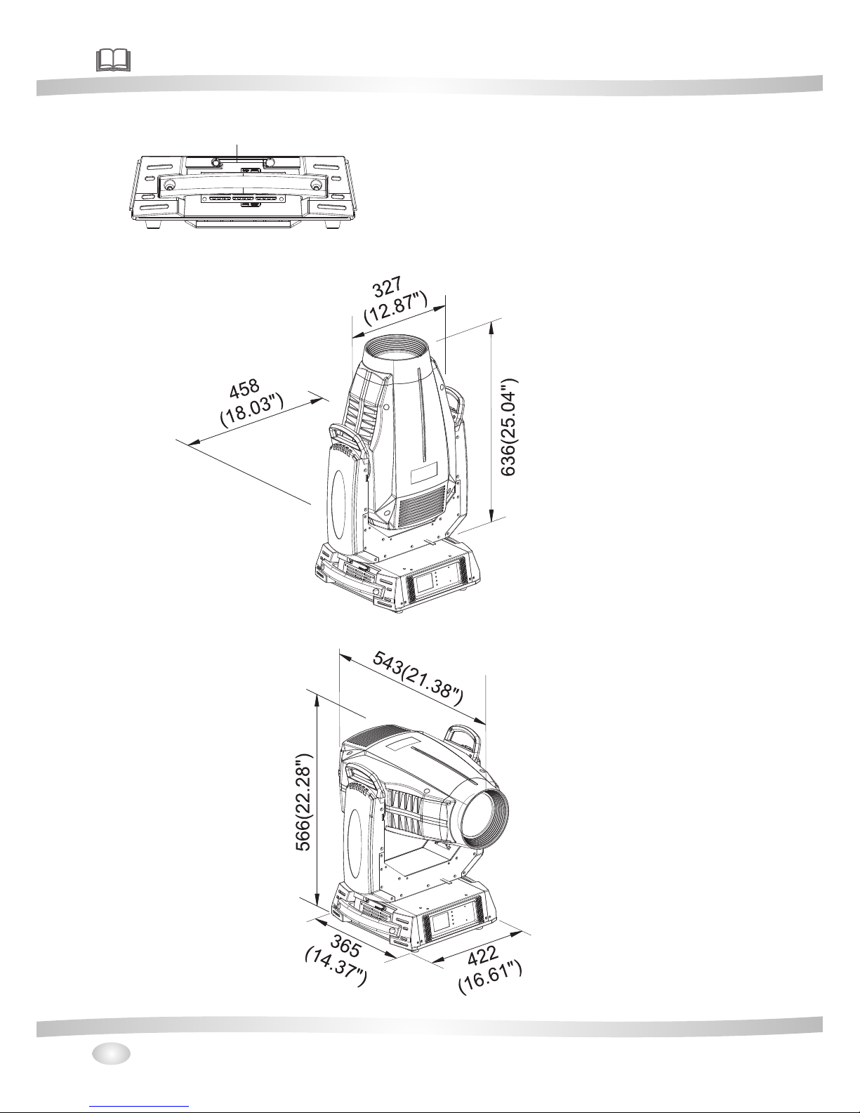
6.Dimension
17.WDMX w ire
Page 11

7.Display control
7.1 Navigation in the Menu
7.2 Display Operation
Using the b uttons or touch scr een, and thi s can be simply and eas ily set the ad dress code and
code.
functio ns
If you view o r modify the lighti ng feature s et, then pre ss ENTE R button, th e display wi ll enter the menu
interfa ce. Both there is sub m enu corres ponding to the func tional ope ration of the main me nu. Each of th e
menus is re presentative of t he specifi c features of the lam p. The speci fic conten ts show s as the table
menu belo w.
Set or brow se lighting funct ion, press U P or D OWN button .
Press ENT ER to save your chang es or enter th e subme nu.Press t he UP or DOWN can ch ange the numerical (in crease or decreas e in value).
Press the M ODE button to retur n to menu. Set a time 1 to 10 m inutes aut omatically exit m enu interf ace
and close t he screen.
Put throu gh power supply, open th e power swit ch of lamps and lante rns, displ ay show the company
website . According to the mai n interfac e, as shown in figure :
In the main i nterface, press " MODE" butt on to vie w the softwa re version, press t he "UP" "DOW N" can modify the D MX address.
If the scre en " " icon i s green,sa id DMX signa l conne ction is nor mal, this state can b e used to chec k thelamps an d lanterns and conn ection bet ween the control ta ble is norma l.
LOGO
9
This lamp c an be set to turn off the aut omatic fli p screen function , touch this " “ i con can be manually
flip scre en.
menu i nterfac e
E1 2 :B us E rr 1 0 1
E1 5 :B al l as t E rr o r 07
E1 7 :B D1 B U S Er r or 9 9
E1 8 :B D2 B U S Er r or 9 9
E1 9 :B D3 B U S Er r or 9 9
Mod e Ent erUp Dow n
00 1
1
00 1 - 02 1Se t t in g s
1
Main in te rf ace
A
001
1
001-0 20
Set tin gs
1
Dmx Input
Wired I np ut
Wirel es s Input
Wirel es s In/
XLR out
Dmx Input
Mod e Ent erUp Dow n
Dmx Address
0 10
Mod e Ent erUp Dow n
Set Up
Inforamti on
Personali ty
Manual Cont ro l
Advanced
Mod e Ent erUp Dow n
Fixture ID
00 10
Channel M od e
Mode1 1-2 4
Mode2 1-2 4
Mode3 1-2 7
Mod e Ent erUp Dow nMod e Ent erUp Dow n
Pr
es
s t
h
is
a
r
ea f
o
r
2
seco
n
ds
t
o
mo
d
ify
t
he
DMX
addr
e
ss.
Main interface
Can v iew the c ompan y LOGO, web
sit e, hard ware, s oftwa re vers ion, da te.
CH-001: 000.0% 000
CH-002:PAN Fine 0 00.0% 000
CH-003:Tilt 000.0% 000
CH-004:Tilt Fine 000.0% 000
CH-005:Cyan 000.0% 000
CH-006:Magenta 000.0% 000
CH-0 07:Yellow 000.0% 000
PAN
Mod e Ent erUp Dow n
Page 12
10
CODE
ERRO INFO CHECK MEASURMENT NOTE
E001 SpiFlashError Check the welding of memory IC
E002 Program Err 1 Check the welding of Chip
E003 Program Err 2 Check the welding of master IC EP3C
E005 BD1Init Error
E006 BD2Init Error
E007 BD3Init Error
E012 BusErr Check main cable ABAB(485) chip
E014 SPDError Check the welding of master IC
E017 BD1 BUS Error
E018 BD2 BUS Error
E019 BD3 BUS Error
E021 Pan FB. Err
E023 Tilt FB. Err
E022 Pan Zero Err
E024 Tilt Zero Err
E025 Prism Err1
E026 Prism Err2
E027 R.Gobo Err1
E028 R.Gobo Err2
E029 A.Gobo Err
E031 Zoom Err
E032 Focus Err
E033 St. Gobo Err
E034 ColourW. Err
E035 Iris Err
E036 Cyan Err
E037 Magenta Err
E038 Yellow Err
E039 CTO Err
E040 Frost Err
E042 B.Fan1 Error
E044 B.Fan2 Error
E053 L.Fan1 Error
E055 L.Fan2 Error
Check the fan of head
Check if the fan(80) of the lamp holder is working
Check the light coupling line, optical coupling switch and a plate of
the relative position measurement
Check cable of sensor, distance and location of ,magnets and sensor
RESET
ERROR
Check the communication signal 485& 485 chip & memory IC
Check the communication signal& welding of communication chip
*Click on t he main menu of the ico n and value to v iew set of the releva nt lightin g information. If t here is
symbol of t he " " on the display, it indi cates that t he device may be wron g , if the symbo l was blue, the
content s are errors appear ed, click to c lear. When the symbo l is yellow, yo u can cli ck on the view a nd
accordi ng to the reference s informat ion to modify, If there is a ny doubt, pl ease consult the re levant
technic al personnel. (-f or details s ee attached table ).
Page 13

11
7.3 Unit Menu
Remark
Dmx Address 001~XXX Dmx Address
Mode1 1~24
Mode2 1~24
Mode3 1~27
Fixture Id 0001~9999 Lamps address
Fixture Times XXXXX h XX m Total working hours
Led Times XXXXh XXm Led working hours
Reset Led Time Reset Led Time
Error List Error details
BOARD 1: XX.XX%
BOARD 2: XX.XX%
BOARD 3: XX.XX%
Fans Monitor Fans Monitor
DMX Values DMX Values
Pan Reverse ON/OFF Pan Reverse(defaul OFF)
Tilt Reverse ON/OFF Tilt Reverse(defaul OFF)
Feedback ON/OFF Pan/Tilt Auto Switch(defaul ON)
Wired Input Wired Input(defaul)
Wireless Input Wireless Input
Wireless In/XLR out Wireless In/XLR out
English
Chinese
Brightness Brightness
Screen Time out 0-10m Screen Time out
Touch Screen ON/OFF Touch Screen(defaul OFF)
Auto Screen ON/OFF Auto Screen(defaul ON)
Reset ALL
Reset Pan/Tilt
Reset Colour
Reset Gobo
Reset other
Channel Chanel Testing
Calibration lnput Password XXXX Chanel Adgusting
Factory Default ON/OFF Reset to orignal parameters
Touch Calibration Touch screen adjusting
Firware UP date Firware UP date
Screen
Manual
Control
Reset
Language language choice
Information
LED Times
Diagnosis Diagnosis
Pan/Tilt
Dmx Input
Advanced
Personality
Set up Channel Mode default Mode1
Page 14

12
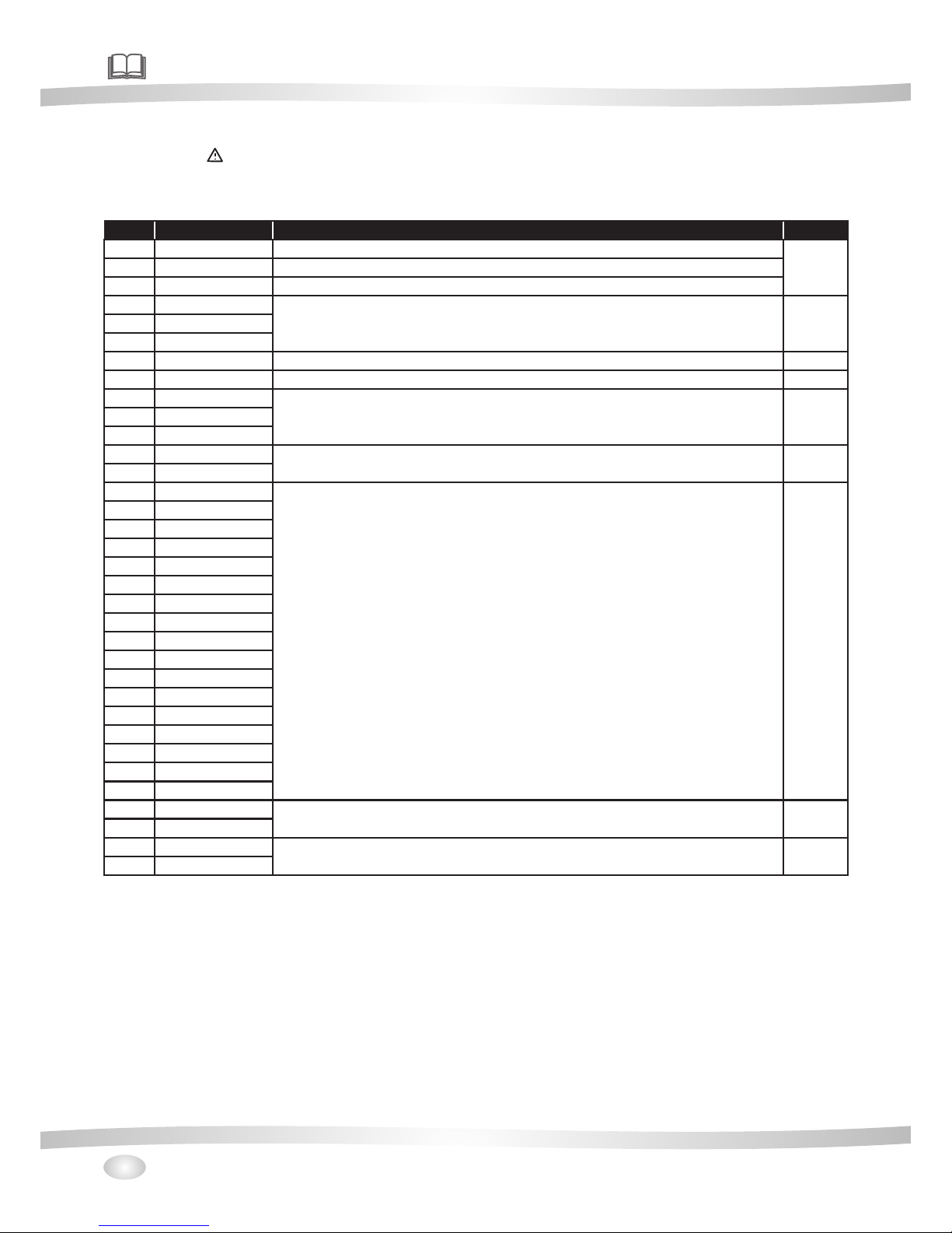
8.DMX protocol
Mode 1Mode 2Mode 3 Fade Type Function Dmx Value
1 20 23 Pan Pan 0-255
2 21 24 Pan Fime Pan Fime 0-255
3 22 25 Tilt Tilt 0-255
4 23 26 Tilt Fime Tilt Fime 0-255
Empty position 0
White→ red 1-19
red 20
red→green 21-39
green 40
green→blue 41-59
blue 60
blue→orange 61-79
orange 80
orange→pink 81-99
pink 100
pink→CTO 101-119
CTO 120
CTO→fluorescence 121-139
fluorescence 140
red 141-146
green 147-152
blue 153-158
orange 159-164
pink 165-170
CTO 171-182
fluorescence 183-188
CW,fast or slow 189-213
stop 214-219
CCW,slow or fast 220-243
Random slow color 244-247
Random medium color 248-251
Random fast color 252-255
6 3 4 Cyan Linear Cyan movement 0-255
7 4 5 Magenta Linear Magenta movement 0-255
8 5 6 Yellow Linear Yellow movement 0-255
9 6 7 CTO Linear CTO movement 0-255
Empty position 0-4
Gobo 1 5-7
Gobo 2 8-10
Gobo 3 11-13
Gobo 4 14-16
Gobo 5 17-19
Gobo 6 21-23
Gobo 1 24-26
Gobo 2 27-29
Gobo 3 30-32
Gobo 4 33-35
Gobo 5 36-39
Gobo 6 40-42
Gobo 1 43-72
Gobo 2 73-102
Rotation
Gobo
Select
9810
color
RotaTing gobo Select 11/9/10
Rotation - set rotation on channel 11/9/10
Gobo Shakes at variable speed from slow to fast 11/9/10
Whatever Position
5 7 8
Single step rotation
The color of the water
Random color
Page 15

13
Gobo 3 103-132
Gobo 4 133-162
Gobo 5 163-192
Gobo 6 193-222
Forwards gobo wheel rotation from fast to slow 223-237
No rotation 238-240
Backwards gobo wheel rotation from slow to fast 241-255
Gobo indexing 0-255
No rotation 0-2
Forwards gobo rotation from fast to slow 3-126
No rotation 127-129
Backwards gobo rotation from slow to fast 130-253
No rotation 254-255
12 10 11
Fine Gobo
Rotation
Fine Gobo Rotation 0-255
Unused Range 0-9
Gobo 1 10-19
Gobo 2 20-29
Gobo 3 30-39
Gobo 4 40-49
Gobo 5 50-59
Gobo 6 60-69
Gobo 7 70-79
Gobo 1 80-99
Gobo 2 100-119
Gobo 3 120-139
Gobo 4 140-159
Gobo 5 160-179
Gobo 6 180-199
Gobo 7 200-219
Forwards gobo wheel rotation from fast to slow 220-236
No rotation 237-238
Backwards gobo wheel rotation from slow to fast 239-255
Prism out 0-10
Prism indexing - set position on channel 15/16/17 11-138
Prism rotation - set position on channel 15/16/17 139-255
Prism indexing 0-255
No rotation 0-2
Forwards Prism rotation from fast to slow 3-126
No rotation 127-129
Backwards Prism rotation from slow to fast 130-253
No rotation 254-255
16 14 15 Frost Focus moves linearly into the light beam 0-255
Open →closed 0-131
Slow pulsation fast pulsation 132-171
Slow open,slow close- fast open,fast close 172-211
Fast open,fast close -fast open,fast close 212-251
Close 252-255
18 12 13 Animation Linear Animation disk insertion 0-255
Continuous Animation disk clockwise rotation at
linearly variable speed from fast to slow
0-124
Stop rotation 125-130
Continuous Animation disk couneter-clockwise
rotation at linearly variable speed from slow to fast
131-255
Rotation
Gobo
Select
11
14
15 17
1615
10 8 9
Animation
disk
rotation
Static
gono
Change
Rot. gobo
indexing
and
rotation
141319
1213
Gobo rotation - set position on channel 10/8/9
Iris
Gobo indexing - set position on channel 10/8/9
9 10
16
Prism
rotation
Prism
insertion
Positioning
Shaking gobos from slow to fast
Prism indexing - set position on channel 14/15/16
Prism rotation - set position on channel 14/15/16
17 1817
11
Mode1 Mode2 Mode3 Fade Type Function Dmx Value
Page 16

14
Mode1 Mode2 Mode3 Fade Type Function Dmx Value
19 Zoom Zoom linearly moves from narrow to wide beam 0-255
20 Zoom Fine Fine Zoom positioning
21 Focus Focus moves linearly from far to near position 0-255
22 Focus Fine Fine focus positioning 0-255
Close 0-3
STROBE SLOW→FAST 4-103
OPen 104-107
PULSATION SLOW→FAST 108-207
Open 208-212
Random slow Strobe 213-225
Random medium Strobe 226-238
Random fast Strobe 239-251
Open 252-255
2 Dimmer Dimmer 0-100% 0-255
3 Dimmer Dimmer Fime 0-255
Unused Range 0-9
Reset Complete -3 sec 10-14
Reset CMY, CTO and color wheel only-3 sec. 15-19
Reset Other -3 sec 20-24
Reset Pan/Tilt -3 sec 25-29
Reset Gobo -3 sec 30-34
Dimmer Curve 1 =linear(1 sec) 35-39
Dimmer Curve 2 =Gamma1.5(1 sec) 40-44
Dimmer Curve 3 =Gamma2.0(1 sec) 45-49
Dimmer Curve 4 =S(1 sec) 50-54
Unused Range 55-104
Disable zoom/focuslinking-1 sec. 105-109
Enable zoom/focus linking,near distance(5meters)
(default setting)-1 sec.
110-114
Enable zoom/focus 115-119
Enable zoom/focus linking, far distance(12meters) -
1 sec.
120-124
Unused Range 125-224
Autofocus priority rotation gobo 225-229
Autofocus priority FX wheel 230-234
autofocus priority Iris 235-239
Unused Range 240-255
Function
2
272424
22 1
Stopper/
Strobe
1
23
21
18
19
20
Page 17

15
9.Maintance and cleaning
It is absol utely essential t hat the fixt ure is kept clean and t hat dust,d irt and s moke fluid r esidues mus t not
buildup o n or within the fixtu re. Otherw ise, the fixtures l ight-out put will be signifi cantly red uced. Regular
cleanin g will not only ensur e the maximu m light-output, b ut will also a llow the fixture to f unction reliably
through o ut its life. A soft lint- free cloth m oistened with any g ood glass cl eaning fluid is rec ommended ,
under no ci rcum stances shou ld alcohol o r solvents be used!
The front obj ective len s will require week ly cleanin g as smoke-fluid te nds to build ing up residues,r educing the lig ht-output very qu ickly.The coo ling-fan s should be cleaned m onthly.
The gobos may b e cleaned wi th a soft brush,The i nterior of the fixt ure should b e cleaned at l east an nually using a vacuum-cleane r or an air-je t.
There are no se rviceabl e parts inside the de vice excep t for the l amp and the fu se.
Replaci ng the fuse: If the lam p burns out, the fine-wire fus e of the devic e might fuse,too. Only replace the
fuse by a fus e of same type and rati ng.Befor e replacing the fus e,unplug m ains lead.
Mainten ance and maintena nce of the ope ration, please co ntact the ma nufacturer or dis tributor.
DANGER:Disconnect from the mains before starting any maintenance work.
10.1 Electrical paramters
10.Electric equipment specification
SOURCE:
POWER:
VOLTAGE:
440W Whit e LED
750W
AC100-2 40V 50/60HZ
Color tem perature:8000K
10.2 Weight and dimensions
Dimensi ons:543X4 X5
NET WEIGHT:36 Kg
Dimensi ons(Carton packag e): 657 X567X661 mm
WEIGHT5Carton pa ckage
8 66
( ):42Kg
mm
10.3 Channel Characteristics
2.Scan: Pan 540°,Tilt244°,Sc an speed adj ustable.Fixtu re could aut o reset.
3.Colour wh eel: one ope n+7colors.hal f-color effe cts,CMY fu nction.
4.Gobo whee l:one open +6 gobos.one , Fix go bo wheel :on e open+7go bos.
5.Prism sys tem:1 rota ting of 8 f aces.
6.Zoom:li near ampli fier.
7.Focus:l inear focu s wi th auto functio n.
8.Demme r:electro nic dimmi n g,linear d imme r.
9. Strobe:elec tronic str obe,with strobe mo de of synchronisti cal,puls e and random .
10. Fire wh eel:fire wh eel with r otation.
1.Channel :24、24、27DM X-512.
10.4 Menu Function
1. .Touch screen,Engli sh/ C hines e menu
Page 18

16
10.5 light table
2.Each DMX Val ue disp layable.
3. Time of aut omatic turning off is able to set on th e display,whe n operatin g pan/tilt,Colo r and gobos,
gobos, st robe are turn off and able to se t freel y.
4. Displa y the time using of lig hting feat ure and lamp a s well as t he times of tu rning on for lamp.
5. You can switch on a nd off the lamp via the con trol pa nel or via you r DMX con troller. It must be no ted
that it has to be cold b efore re-strick ing.
6.After the DMX si gnal is disconnec ted, th e display will be bri ght and dark.
7.Softw are upg rade function.
Flare dia meter(m)
The minim um Angle 8.6°Flare dia meter(m)
Maximum An gle36°Flare diame ter(m)
Project ion distance(m)
10
15
20
Φ1.5 2
Φ0.7 6
Φ2.2 8
Φ6.4 8
Φ3.2 4
Φ9.7 2
2130
532
25
Φ3.0 4
Φ12. 9 6
132
236
28920
12517 31295563
5
Φ3.8 4
Φ16. 2
85
2002
36°
36 Lux)°Illumin ance(Lux) (
8.6°Illum inance(Lu x)(L ux)
8.6°
Page 19

17
Effect whee l
Rgobo whe el
Glas s de sign, Insid e diameter3 4.7mm,effec ti ve diamet er 3 0mm.
10.6 Gobo wheel
Inte gr a,Inside di ameter 162m m,effective
diam eter 25.5mm
Inte gr a,Inside di ameter mm, effe ctive
diam eter 124mm
130
Fix gobo wh eel
Page 20

18
10.7 Color wh eel
CTO
Magnets
Pink
blue
red
Green
orange
Fluores cent
Page 21

19
Note : The above i nformation is for reference onl y, the fina l interpr etation i s belong to m anufacturer.
11.Electronic drawing
L
N
AC
IN
DC48V
DC5V
+
-
Titl
Motor
Pan
Motor
Titl EN
Pan EN
Titl Sensor
Pan Sensor
L
N
Three Phase Motor Driver Board
L
+
-
G
LED
Fan
F2
LED
Fan
F1
LED Control
-
Cyan
Magnta
Yellow
Static
Gobo
Wheel
M1
M2
M3
M4
M5
M6
M7
M8
(YM)
(MM)
Magnta
(CM)
(GM)
M1
M2
M3
M4
M5
M6
M7
M8
Frost
Motor
Iris
(4PM)
(FO)
(ZO)
(4PM)
Power Supply
Power Supply
+
Color
Wheel
(DGM)
(IR)
Iris
(CM)
(CTOM)
60
Fan
80
Fan
Power Supply
RS485
RS485
RS485
+3V3
NTCNTC+
PWM2
PWM1
GND
Battery
DMX
FUSE
Page 22

MADE IN CHINA
 Loading...