

Page 1
www.jokabsafety.com
6:14
www.jokabsafety.com
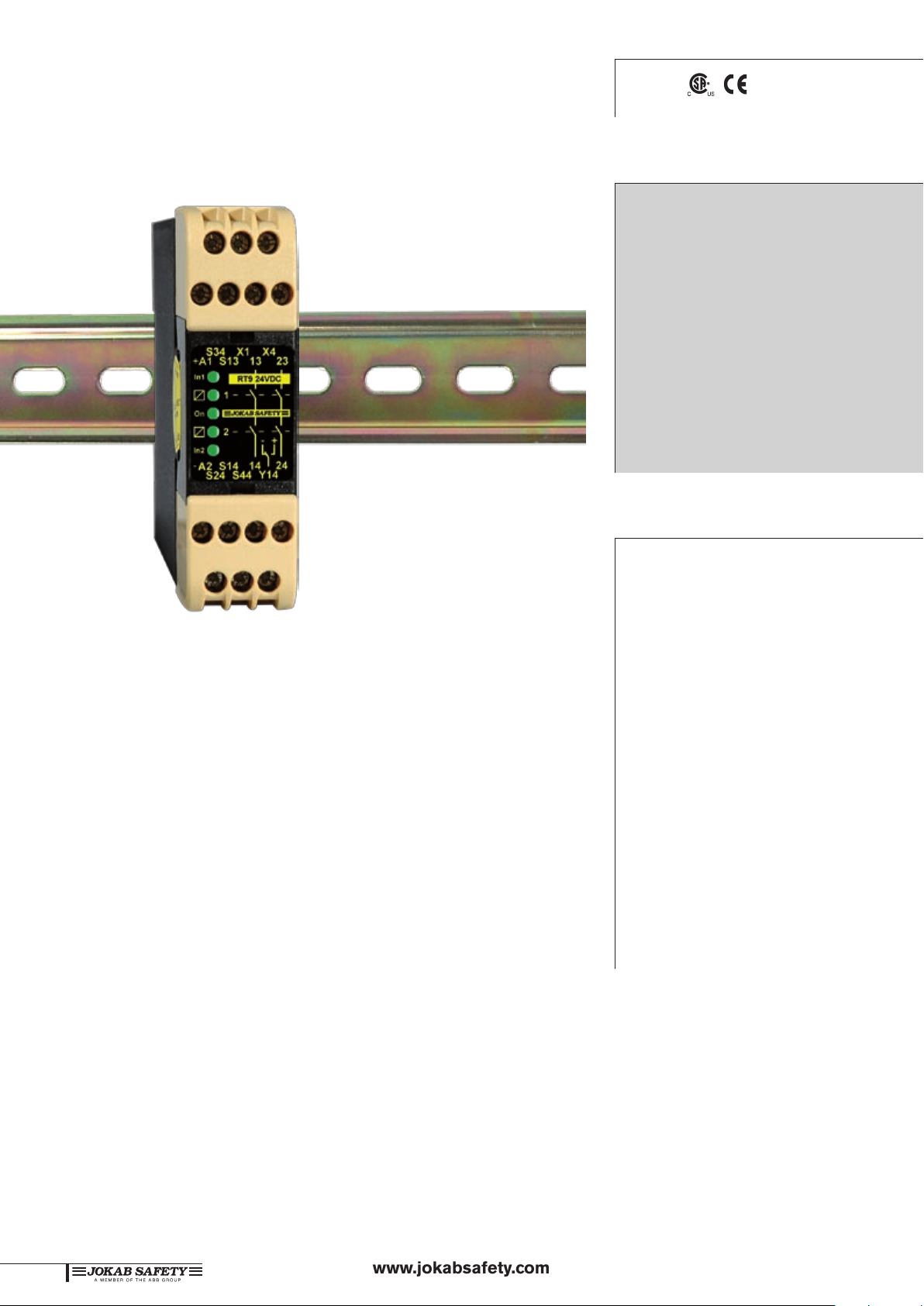
Safety relay
RT9
Approvals:
TÜV Nord
Safety relay for:
Emergency stops
Light curtains
Three position devices
Interlocked gates/hatches
Magnetic switches
Light beams
Safety mats
Contact strips
Foot operated switches
Would you like a small safety relay for all your safety
applications?
Then choose the compact RT9 universal relay to supervise both
your safety devices and the internal safety of your machinery. In
addition, you can select the safety level that is required for each
installation. All this is possible due to the RT9 offering the most
versatile input option arrangement available on the market. The
RT9 can therefore replace many other relays.
Other RT9 options include selection of either manual supervised
or automatic resetting. The manual supervised reset can be used
for gates and other safety devices that can be bypassed. Automatic
reset can be used for small safety hatches, if deemed acceptable
from risk assessment.
In addition, the RT9 has a double information output that will
indicate e.g if a gate is open or if the relay needs resetting.
The RT9 uses the latest component technology and modern assembly techniques to ensure a highly cost effective solution.
Choose the RT9 to simplify your safety circuits and reduce your
costs.
Features:
Five input options
Single or dual channel input
Manual supervised or automatic reset
Test input for supervision of
external contactors
Width 22.5 mm
LED indication of supply,
inputs and outputs, shortcircuit and low voltage level
2 NO relay outputs
One changeover relay with
a double information output
Supply 24 VDC
Quick release connector
blocks
Page 2
www.jokabsafety.com
6:15
Technical information – RT9
Short circuit
protection
Automatic
fuse
Inputs
The RT9 can be configured to operate in either of the following
input options:
Single channel, 1 NO contact from +24VDC, 1. category 1,
up to PL c
Dual channel, 2 NO contacts from +24VDC, 2. category 3,
up to PL d
Dual channel, 1 NO, 1 NC contact from +24VDC, 3. category
4, up to PL e
Dual channel, 1 NO contact from 0V and 1 NO contact 4.
from +24VDC, category 4, up to PL e
Safety mat/contact strips, 1 ‘contact’ from 0V and 1 5.
‘contact’ +24VDC, category 3, up to PL d
When the input/inputs are activated and the test/supervised reset
is complete, relays 1 and 2 are energised. These are de-energised
when the input/inputs are de-activated in accordance with the
input option chosen or in case of a power failure.
Relays 1 and 2 must both be de-energized before the RT9 can
be reset.
Relay output status information
The RT9 has a changeover contact relay output that can be connected to a PLC, control lamp, computer or similar. The output
gives information about the status of the relay.
Indication of low voltage
The ‘On’ LED will flash if the relay supply voltage falls below an
acceptable level. This indication will also be given if a monitored
safety mat/contact strip is actuated. Please see Connection option 5.
Safety level
The RT9 has internal dual and supervised safety functions. Power
failure, an internal faulty component or external interference will
not present a risk to options with the highest safety level. A manual
reset requires that the reset input is closed and opened before
the safety relay outputs are activated. A short-circuit or a faulty
reset button is consequently supervised.
When the RT9 is configured for dual channel input, both the
inputs are supervised for correct operation before the unit can
be reset.
The input options 3 and 4 have the highest safety levels as all
short-circuits and power failures are supervised. This in combination with an internal current limitation makes the relay ideal for
supervision of safety mats and contact strips.
Regulations and standards
The RT9 is designed and approved in accordance with appropriate directives and standards. See technical data.
1
2
3
4
5
Reset and testing
The RT9 has two reset options; manual and automatic. The manual
supervised reset can be used when the RT9 is monitoring safety
devices that can be bypassed, i.e. to ensure that the outputs of
the safety relay do not close just because a gate is closed. The
automatic reset option should only be used if appropriate from a
risk point of view.
Due to special internal circuits the RT9 can be automatically
reset regardless of the operational voltage rise time, this being
an important factor when large loads are started up on the same
power supplies at the same time.
In addition, the RT9 can also test (supervise), if for example,
contactors and valves etc are de-energised/de-activated before
a restart is made.
Connection of supply - RT9
DC supply
Connection examples
For examples of how our safety relays can solve various safety
problems, please see the section “Connection examples”.
6
7
8
9
10
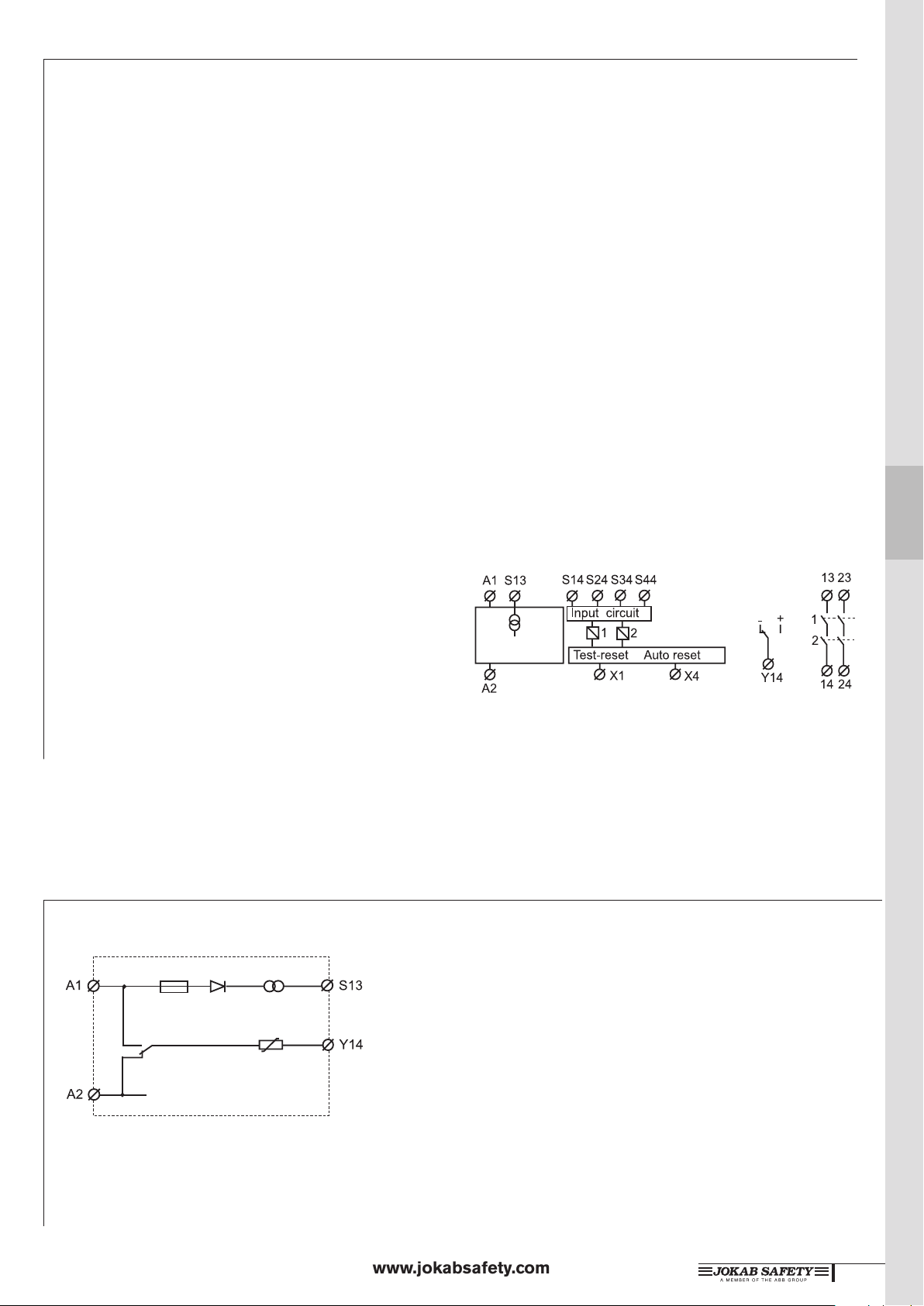
The RT9 should be supplied with +24 V on A1
and 0 V on A2.
NOTE
If cable shielding is used this must be connected
to an earth rail or an equivalent earth point.
11
12
13
14
Page 3

www.jokabsafety.com
6:16
www.jokabsafety.com
Connection of safety devices - RT9
1. SINGLE CHANNEL, 1 NO from
+24V
The input (contact to S14) must be closed
before the outputs can be activated. When
the input contact is opened, the relay safety
output contacts open.
2. DUAL CHANNEL, 2 NO from +24V
Both input contacts (S14 and S34) must
be closed before the relay outputs can be
activated. The safety relay contacts will
open if one or both of the input contacts
are opened. Both the input contacts must
be opened and reclosed before the relay
can be reset.
A short-circuit between inputs S14 and
S34 can only be supervised if the device
connected to the inputs has short-circuit
supervised outputs, e.g. JOKAB Focus
light curtains
3. DUAL CHANNEL, 1 NO, 1 NC from
+24V
One input contact must be closed (S14) and
one opened (S44) before the relay outputs
can be activated.
The safety relay contacts will open if
one or both of the inputs change state or
in case of a short-circuit between S14 and
S44. Both inputs must be returned to their
initial status before the relay outputs can be
reactivated.
4. DUAL CHANNEL, 1 NO from +24V,
1 NO from 0V
Relay functions as option 2, but a shortcircuit, in this case between inputs S14
and S24, is supervised (safety outputs are
opened).
5. Safety mat/Contact strip
Both ‘contact’ inputs from a inactivated
safety mat/contact strip must be made
in order to allow the RT9 relay outputs
to be activated. When the safety mat/
contact strip is activated or a short-circuit
is detected across S14-S23, the relay will
de-energize (safety contacts open) and
the ‘ON’ LED will flash. As output S13
has an internal current limit of 70 mA, the
RT9 will not be overloaded when the mat/
contact strip is activated or a short-circuit
is detected.
Reset connections - RT9
Manual supervised reset
The manual supervised reset contact
connected to input X1 must be closed
and opened in order to activate the relay
outputs.
Output connections - RT9
Relay outputs
The RT9 has two (2 NO) safety outputs.
In order to protect the output contacts
it is recommended that loads (inductive)
are suppressed by fitting correctly chosen
VDR’s, diodes etc. Diodes are the best arc
suppressors, but will increase the switch off
time of the load.
Automatic reset
Automatic reset is selected when A1(+), X1
and X4 are linked. The relay outputs are then
activated at the same time as the inputs.
Information outputs
The RT9 has a single changeover contact
information relay output.The relay output
Y14 is connected internally to 0V and 24V
in the following way:
• Y14 is internally closed to 0V when
the RT9 is not reset.
• Y14 is internally closed to +24V when
the relay is reset.
Testing external contactor status
Contactors, relays and valves can be
supervised by connecting ‘test’ contacts
between A1(+) and X1. Both manual
supervised and automatic reset can be
used.
Page 4

www.jokabsafety.com
6:17
Technical data – RT9
Manufacturer ABB AB/Jokab Safety, Sweden
Article number/Ordering data
RT9 24DC 2TLJ010029R0000
Colour Black and beige
Weight 210 g
Supply
Voltage (A1-A2) 24 VDC ±20%
Power consumption
Nominal voltage 2 W
Connection S13 Short-circuit protected voltage
output
70 mA ± 10% current
limitation. Is used for the inputs
S14, S34 and S44.
Input currents
(at nominal supply voltage)
S14 (+) input 30 mA
S24 (0V) input 20 mA
S34 (+) input 20 mA
S44 (+) input 25 mA
Reset input X1
Supply for reset input + 24VDC
Reset current 300 mA current pulse at
contact closure, then 30 mA
Minimum contact closure time
for reset 80 ms
Minimum contact closure time
(at low limit voltage -20%)
Maximum external
connection cable
resistance at a nominal
voltage for
S14, S24, S34 300 Ohm
S44, X1 150 Ohm
Response time
At Power on <100 ms
When activating (input-output) <20 ms
When deactivating (input–
output)
At Power Loss <80 ms
Relay outputs
NO 2
Maximum switching capacity
Resistive load AC 6A/250 VAC/1500 VA
Inductive load AC AC15 240VAC 2A
Resistive load DC 6A/24 VDC/150 W
Inductive load DC DC13 24VDC 1A
Max. total switching capacity: 8A distributed on all contacts
Minimum load 10 mA/10V (if load on contact
Contact material Ag+Au flash
Fuses Output (External) 5A gL/gG
Conditional short-circuit
current (1 kA) 6A gG
Mechanical life 107 operations
Relay information output
Y14 (Changeover contacts)
-(0V) Indicates that RT9 is not reset.
+(24V) Indicates that RT9 is reset.
Maximum load of Y14 250 mA
Short-circuit protection for
information output Internal automatic fuse
100 ms
<20 ms
has not exceeded 100 mA)
LED indication
On
In1 In2
1 2
Mounting
Rail 35 mm DIN rail
Connection blocks
(detachable)
Maximum screw torque 1 Nm
Maximum connection area:
Solid conductors 1x4mm2/2x1,5mm2/12AW G
Conductor with socket contact 1x2 ,5mm2/2x1m m
Protection class
Enclosure IP 40 IEC 60529
Connection blocks IP 20 IEC 60529
Operating temperature range -10°C to + 55°C (with no icing
Operating humidity range 35% to 85%
Impulse Withstand Voltage 2.5kV
Pollution Degree 2
Performance (max.)
The relays must be cycled at
least once a year.
Conformity 2006/42/EC, 2006/95/EC,
Connector blocks are detachable
(without cables having to be disconnected)
Supply voltage OK, the LED
is on. Flashing light in case
of under-voltage, overload or
current limiting
Indicates that the input
conditions are fulfilled.
Indicates that the output relays
have been activated.
2
or condensation)
Category 4/PL e
(EN ISO 13849-1:2008)
SIL 3 (EN 62061:2005)
PFHd 9.55E-09
2004/108/EC
EN 954-1:1996, EN
62061:2005
EN ISO 13849-1:2008
1
2
3
4
5
6
7
8
9
10
11
12
13
14
 Loading...