

Page 1

EMERGENCY STOPS AND PILOT DE VICES 6– 1
—
Emergency stops
and pilot devices
6– 2 Introduction and overview
6– 6 Emergency stop buttons
Smile, INCA, EStrong and Compact
6– 16 Safety stop buttons
Smile, INCA, and Compact
6– 24 Pull wire emergency stop switch
LineStrong
6– 34 Push-button box
Smile 41
6– 40 Reset button
Smile
6– 46 Pilot devices
Modular and Compact range
6
Page 2
6– 2 SAFETY PRODUCTS CATALOG ABB JOKAB SAFETY
—
Introduction and overview
Selection guide
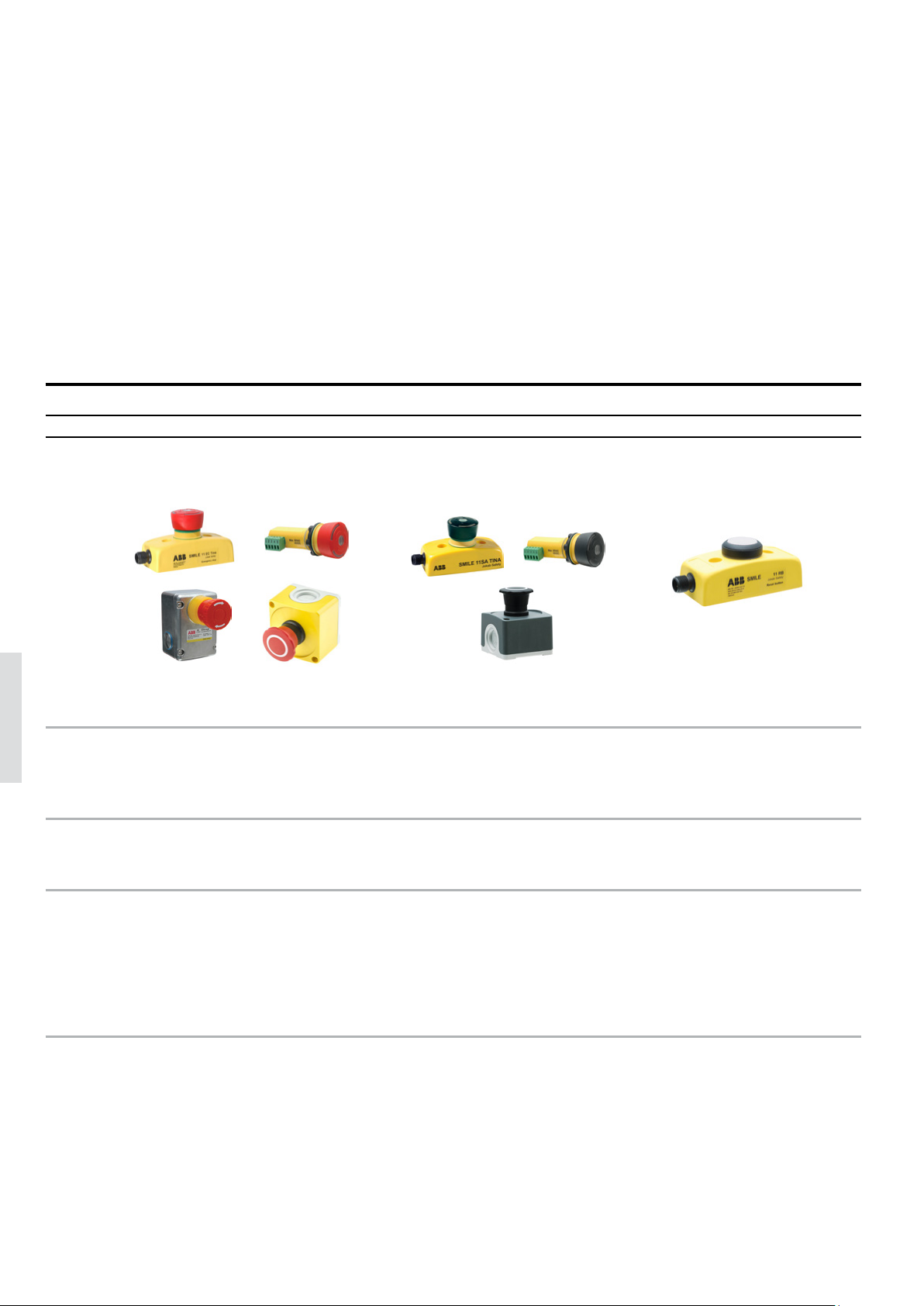
ABB offers a full range of buttons and pull wires for emergency stop functions,
as well as pilot devices for e.g. reset functions.
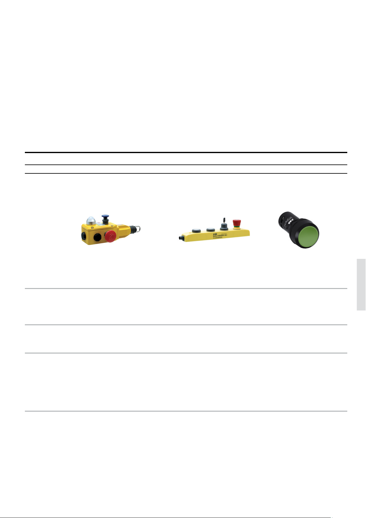
Emergency stop buttons Safety stop buttons Reset buttons Pull wire emergency stop switches Push button boxes Pilot devices
Name
Image Image
Smile, Inca, EStrong, Compact Smile, Inca, Compact Smile
6
Description
Applications
Advantages
Emergency stop buttons for external
mounting and panel mounting in
different sizes and material
Safely stop dangerous machine
functions
Models with:
- Compact size
- Robust enclosure for harsh
environments
- Quick installation with M12 connectors
- LED indication
Safety stop buttons for external
mounting and panel mounting
Safely stop a limited part of a
dangerous machine
Models with:
- Compact size
- Robust enclosure for harsh
environments
- Quick installation with M12
connectors
- LED indication
Small and easy to install reset
button
Pushbutton for resetting safety
devices
- Compact size
- Quick installation
- M12 connector
- LED indication
Page 3
EMERGENCY STOPS AND PILOT DE VICES 6– 3
Name
Description
Applications
LineStrong Smile 41 Modular range, compact range
Emergency stop switches in robust
enclosures for pull wires of various
lengths.
Gathers up to four push buttons, including emergency stop,
in a single compact device
Push buttons, selector switches, pilot lights, joysticks and
signal towers in a compact and
robust design
Emergency stop line to safely stop
conveyor belts and long transporta-
Emergency stop and pushbuttons
in one device
For control and indication of machines and processes
tion lines.
6
Advantages
- Up to 200 m wire with one switch
- Reliable mechanical connection
- Robust construction
- Compact size
- Quick installation
- M12 connector
- LED indication
- Highly adaptable with several
button colors
- Compact size
- Up to IP69K
- Long life-time thanks to
self-cleaning contacts
- Quick snap-on design for
simple installation without
tools
Page 4
6– 4 SAFETY PRODUCTS CATALOG ABB JOKAB SAFETY
—
Introduction and overview
Selection orientation
Why an emergency stop is necessary
If a machine breaks down or if someone is in danger, anyone should be able to stop the machine, regardless of their knowledge of the specific application.
When a safety stop could be used
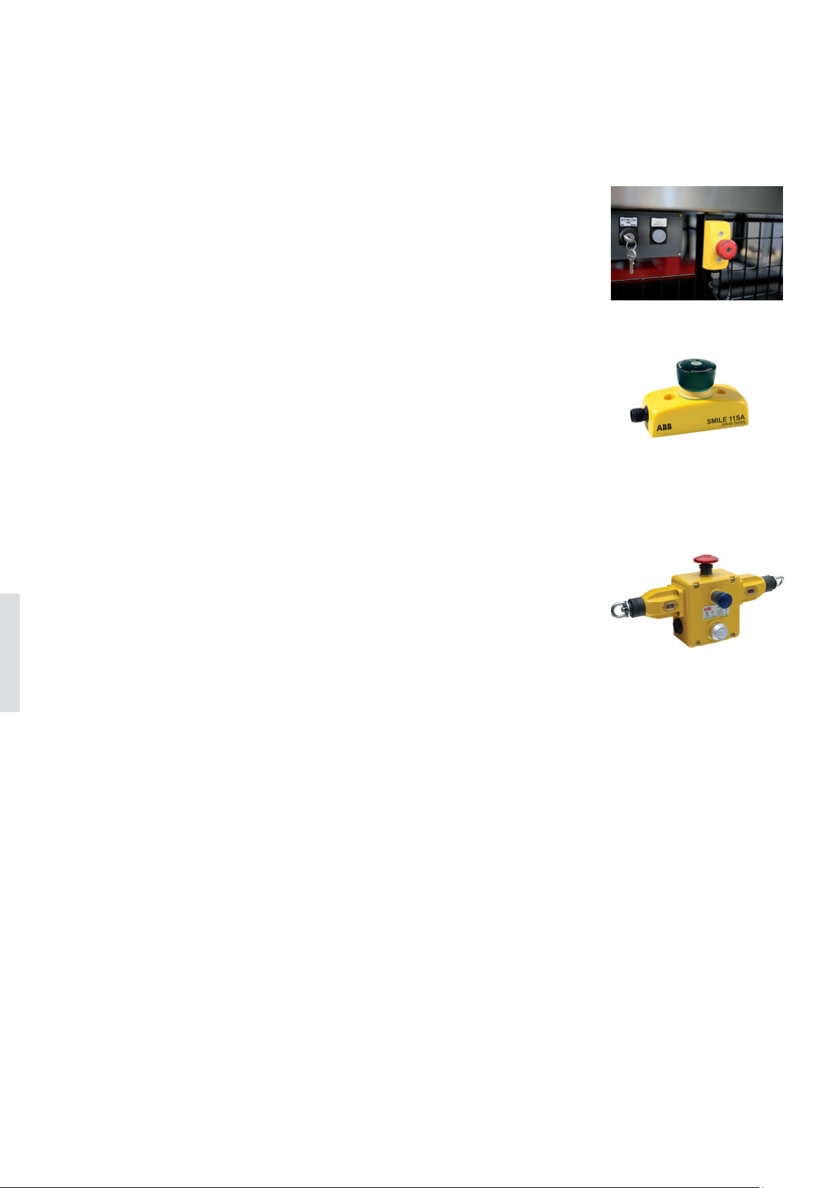
A safety stop (also called machine stop) should be used to safely stop a part of the machine,
e.g. as a stop for an individual hazardous motion. It should not be used as an emergency
stop and stop the complete machine. Likewise, an emergency stop with red push button
must not be used as a safety stop.
In order to separate the safety stop function from the emergency stop function, the safety
stop buttons should be colored black.
When a pull wire emergency stop could be used
A pull wire emergency stop is easier to install than a system of several emergency stop
buttons along a carriage path which makes it ideal for installations over long distances.
LineStrong can handle wires up to 200 m on one single switch and the emergency command
can be initiated from any point along the installed wire length.
6
Page 5

EMERGENCY STOPS AND PILOT DE VICES 6– 5
—
Introduction and overview
Standards
Important standards to follow when implementing emergency stop functions are e.g. EN ISO 13850 and EN ISO 60204-1.
Stop categories
The following stop categories are defined in the standards:
Stop Category 0 stopping by immediate removal of power to the machine actuators
Stop Category 1
Stop Category 2 a controlled stop with power left available to the actuators
Note that these categories should not be confused with the categories used to describe the architecture when calculating PL
in EN ISO 13849.
to be suitable for emergency stops.
The risk assessment should determine which stop category to use, but stop category 2 is normally considered not
a controlled stop with power available to the machine actuators to achieve the stop and then removal of
power when the stop is achieved
Text and symbols
Neither the emergency stop nor its background should be labelled with text or symbols. It has previously been common with
white arrows indicating the direction of unlatching, but this is not allowed anymore.
Location and signs
The risk assessment should determine the locations of the emergency stop buttons, but they should in general be placed at
operator stations, at locations where man/machine interaction is required and at entry/exit points. Signs to mark the location
of emergency stops are not required, but if used they should be green with white markings.
6
Page 6
6– 6 SAFETY PRODUCTS CATALOG ABB JOKAB SAFETY
—
Emergency stop buttons
Smile, INCA, EStrong and Compact
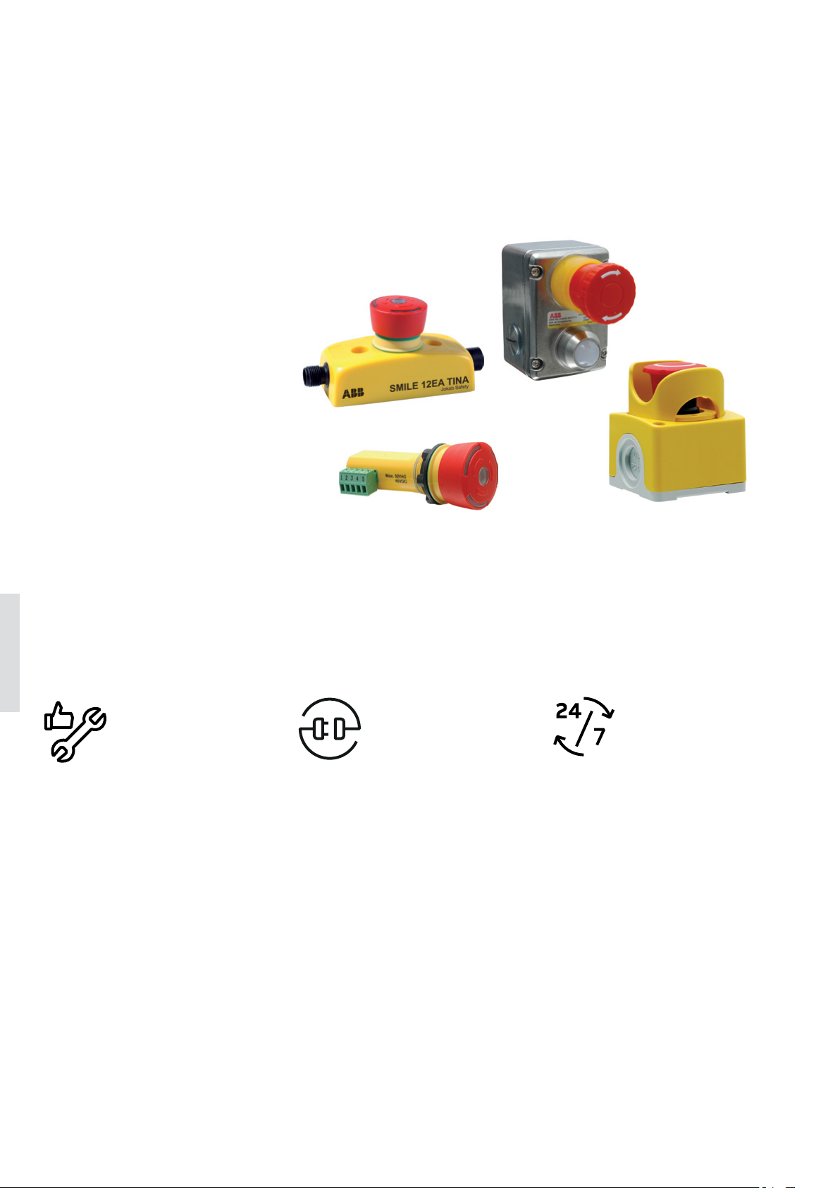
Emergency stop buttons are used to
safely stop dangerous machine functions.
ABB offers a wide range of emergency
stop buttons for external mounting or
panel mounting, with plastic or metal
housing and for different types of
connections.
6
Easy to install
Compact size
Models with a compact and appealing
housing saves space and makes it easy
to place.
Quick installation
Quick and easy installation of models
with features such as centered mounting holes, removable terminal blocks
and M12 connectors.
Optimum interface
Highly adaptable
Several models to choose between
depending on position, installation
and function.
Reliable in extreme conditions
Robust models and models in stainless
steel for use in demanding environments.
Continuous operation
LED diagnostics
Models with integrated LED diagnostics reduce downtime when troubleshooting.
Serial connection
Tina models save cable length and installation time with serial connection.
Page 7
EMERGENCY STOPS AND PILOT DE VICES 6 – 7
—
Models and application
Emergency stop buttons
Models for external mounting
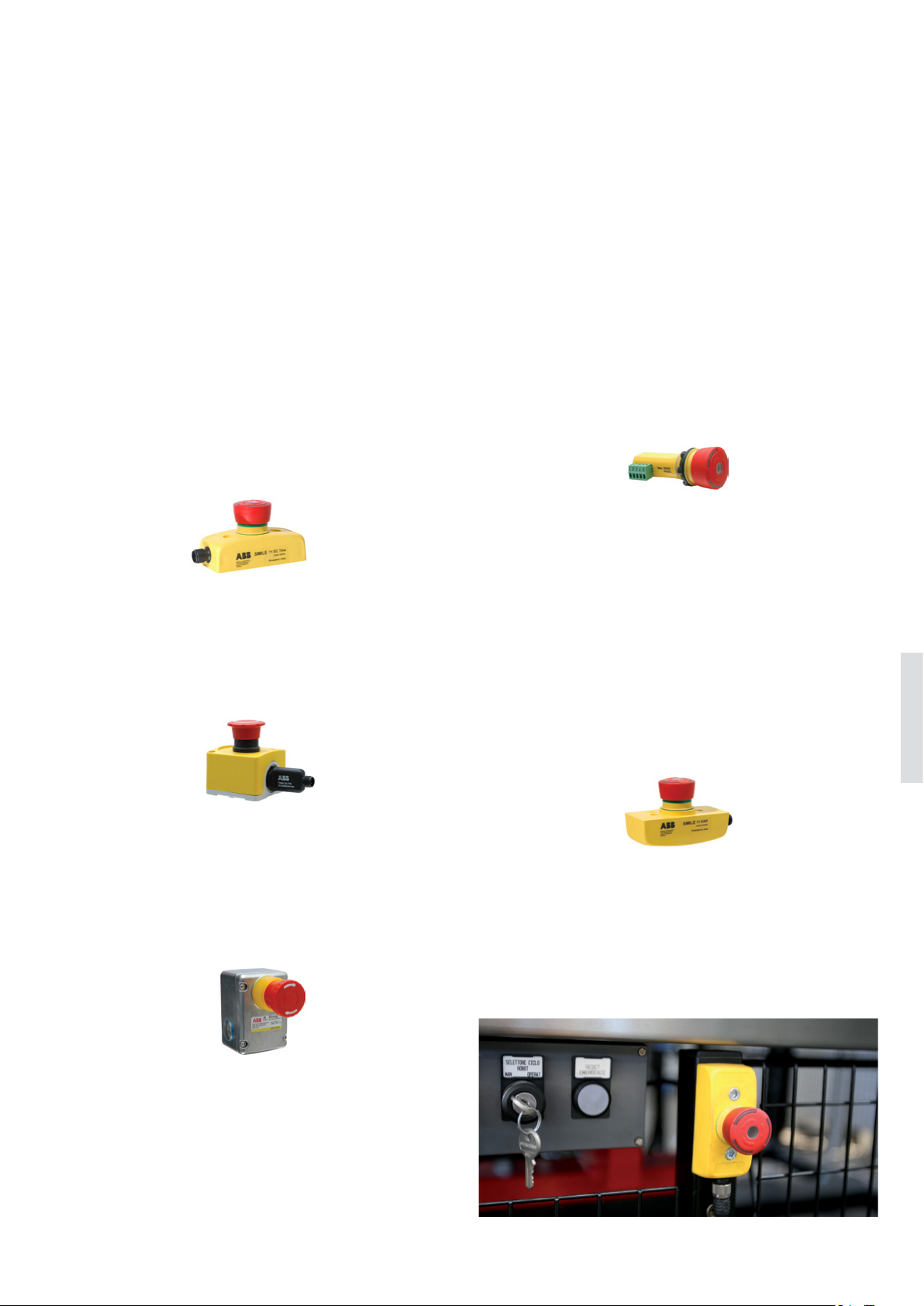
Smile
Smile is a small and easy to install emergency stop button.
Its size allows mounting in reduced spaces, and its centered mounting holes makes it especially easy to mount on
aluminum extrusions (e.g. Quick-Guard fencing system).
Smile is available with M12 connectors or cable.
Smile has an integrated LED in the button that shows the
status and simplifies error tracking.
The standard models of Smile have 2 contacts and can be
used with safety controllers from all brands. Smile Tina
models belong to the ABB DYNlink solution, with the advantages of serial connection using only one channel and
still reaching Cat. 4/PL e.
Compact
Compact emergency stop buttons offer a robust enclosure
with a high IP rating that fulfill the demands in severe and
humid environments, such as food and beverage industry.
Compact can be fitted with a Tina adapter for use in a DYNlink solution (Tina 2A, Tina 2B or Tina 3A).
Models for panel mounting
INCA
INCA is an emergency stop button for panel mounting,
designed for installation in 22.5 mm holes. Its removable
terminal block facilitates connection and exchange.
INCA has an integrated LED in the button that shows the
status and simplifies error tracking.
The standard model of INCA has 2 contacts and can be used
with safety controllers from all brands. INCA Tina models
belongs to the ABB DYNlink solution, with the advantages of
serial connection using only one channel and still reaching
Cat. 4/PL e.
Smile Reverse
Smile Reverse is identical to the regular Smile emergency
stop button besides from being reversed in order to be
mounted on the back side of a panel. Smile Reverse has an
IP65 housing that makes it suitable in panels where moisture and dust may occur.
Smile Reverse has an integrated LED in the button that
shows the status and simplifies error tracking.
The standard model of Smile Reverse has 2 contacts and can
be used with safety controllers from all brands. The Smile
Reverse Tina model belongs to the ABB DYNlink solution,
with the advantages of serial connection using only one
channel and still reaching Cat. 4/PL e.
6
EStrong
EStrong is an emergency stop button designed to provide
a robust unit in exposed and severe environments. The unit
has a stainless steel enclosure with IP69K rating that withstands high pressure and high temperature wash-down. It is
therefore ideally suited for industries with special demands,
such as food processing or chemical industry.
Application
Emergency stop buttons are used to safely stop a dangerous machine function in order to prevent an accident, or
minimize the consequences of an accident. An emergency
stop should be a complement to other safety devices, and
not a replacement for them.
Page 8
6– 8 SAFETY PRODUCTS CATALOG ABB JOKAB SAFETY
—
Features
Emergency stop buttons
Communication features
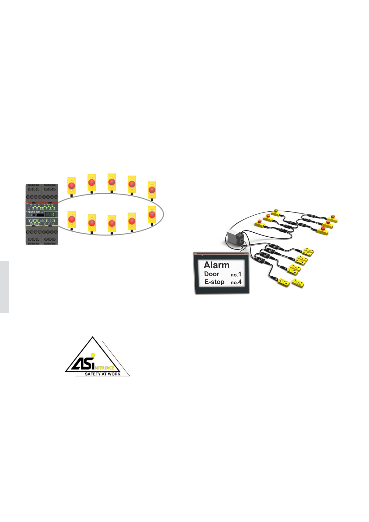
DYNlink
Emergency stop buttons with Tina in their name belong to
the DYNlink solution, which enables serial connection using
only one channel and still reaching Cat. 4/PL e. DYNlink
devices must be used with Vital safety controller or Pluto
programmable safety controller. Up to 30 DYNlink devices
can be connected in series to Vital and up to 10 can be connected to each input on Pluto.
StatusBus
StatusBus is a simple and cost effective way to collect the
status information of emergency stops and safety sensors. The StatusBus functionality is available with some
DYNlink devices and allows to collect the status of each
individual safety device, even when connected in series. A
Pluto programmable safety controller must be used to read
the StatusBus information, and a single input on Pluto can
collect the status of up to 30 safety devices. The devices are
connected using standard cable and M12-5 connectors. No
specific bus cable or extra communication module is
necessary.
AS-i
Smile is available in a model compatible with the AS-i safety
bus. Smile AS-i can be used with any AS-i monitor. AS-i is a
bus system that offers a very simple connection of up to 31
6
safety devices to one monitor according to PL e and makes
it easy to move, remove and add safety devices. When Smile
AS-i is used with Pluto programmable safety controller, no
other AS-i master or monitor is necessary, and no specific
knowledge of AS-i is required.
Page 9
EMERGENCY STOPS AND PILOT DE VICES 6– 9
—
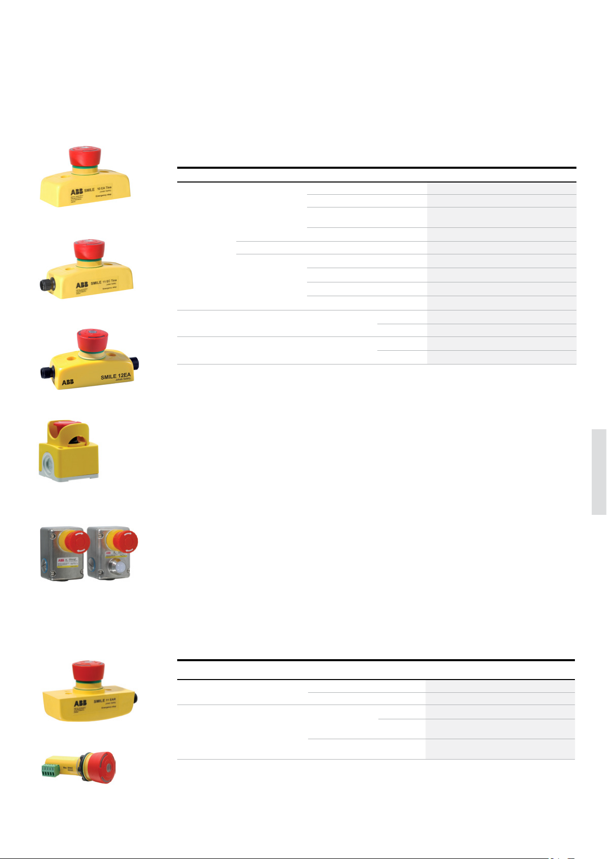
Ordering information
Emergency stop buttons
—
External mounting
Description Type of safety signal Connection type Feature Typ e Order code
Compact size
2TLC172863F0201
Smile 10 EA Tina
2TLC172857F0201
Smile 11 EC Tina
Smile 12 EA
Plastic housing
IP65
Plastic housing
IP66, IP67 and IP69K
Metal housing
IP67 and IP69K
* Can be adapted to DYNlink with Tina
2TLC172187F0201
DYNlink 1 m cable from bottom Status LED Smile 10 EA Tina 2TLA030050R0400
1 x M12-5 male Status LED Smile 11 EA Tina 2TLA030050R0000
1 x M12-5 male Status LED,
Smile 11 EC Tina 2TLA030050R0900
StatusBus
2 x M12-5 male Status LED Smile 12 EA Tina 2TLA030050R0200
AS-i 1 x M12-4 male Status LED Smile 11 EA AS-i 2TLA030052R0000
2 NC 1 m cable from bottom Status LED Smile 10 EA 2TLA030051R0400
1 m leads from bottom - Smile 10 EK 2TLA030051R0600
1 x M12-5 male Status LED Smile 11 EA 2TLA030051R0000
2 x M12-5 male Status LED Smile 12 EA 2TLA030051R0200
2 NC* 2 x M20 conduits - CEPY1-1002 (Compact) 1SFA619821R1002
With shroud CEPY1-2002 (Compact) 1SFA619821R2002
2 NO + 2 NC 3 x M20 conduits Status LED EStrongZ LED 2TLA050220R0222
- EStrongZ 2TLA050220R0020
ABB Compact emergency stop
shroud
EStrongZ and EStrongZ LED
Smile 11 EAR
2TLC172689F0201
—
Panel mounting
IP rating Depth Connection type Type of safety signal Feature Typ e Order code
IP65 26 mm 1 x M12-5 male DYNlink Status LED Smile 11 EAR Tina 2TLA030050R0100
2 NC Status LED Smile 11 EAR 2TLA030051R0100
2TLC172861F0201
Button IP65,
connector IP20
53 mm Removable termi-
nal block
DYNlink Status LED INCA 1 Tina 2TLA030054R0000
Status LED,
INCA 1 EC Tina 2TLA030054R1400
StatusBus
2 NC Status LED INCA 1 2TLA030054R0100
6
INCA 1
2TLC172363F0201
Page 10
6– 10
SAFETY PRODUCTS CATALOG ABB JOKAB SAFETY
—
Accessories
Emergency stop buttons
—
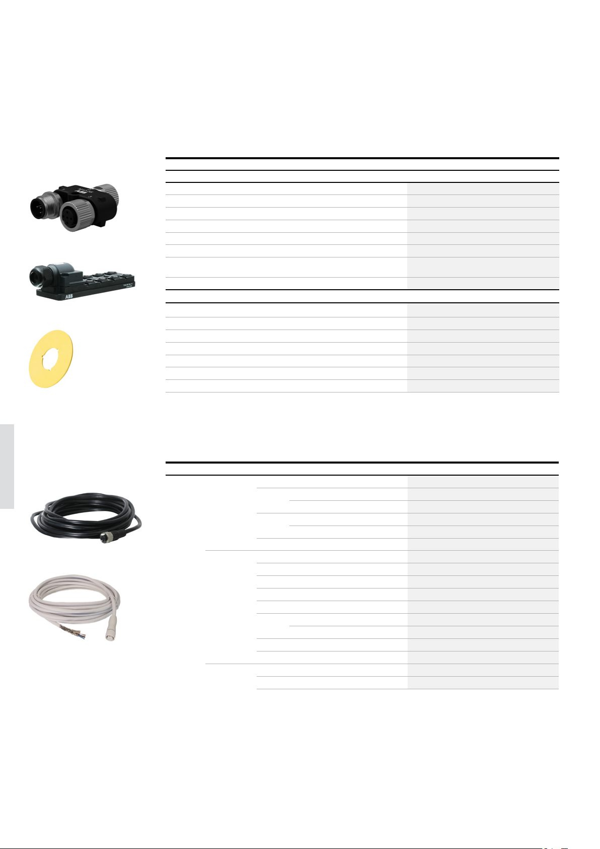
Connection accessories
Description Typ e Order code
Connection accessories
M12 Y-connector for serial connection of device with StatusBus functionality. M12-3S 2TLA020055R0600
M12 Y-connector for serial connection of devices without StatusBus functionality. M12-3A 2TLA020055R0000
Connection block for the serial connection of up to 4 DYNlink devices with 12-5 connectors.
2TLC172034V0201
M12-3S
Tina 8A
2TLC172906F0201
E-sign 22.5
Connection block for the serial connection of up to 8 DYNlink devices with 12-5 connectors.
Adaptation unit for DYNlink solution with M20 fitting. For e.g. Compact. Tina 2A* 2TLA020054R0100
Adaptation unit for DYNlink solution, internal assembly. For e.g. Compact. Tina 2B* 2TLA020054R1100
Adaptation unit for DYNlink solution with M20 fitting and M12 connector. For e.g. con-
necting Compact to Pluto/Vital.
Termination for Smile 12 JST2 2TLA030051R1300
Accessories
2TLC172471F0201
Emergency stop sign, yellow, no text, for INCA (22.5mm) E-Sign 22.5 2TLA030054R0900
Emergency stop sign, yellow, no text, for Smile (32.5mm) E-Sign 32.5 2TLA030054R1000
Yellow surround for Inca Surround for Inca 2TLA030054R0400
Yellow shroud for Compact CA1-8053 1SFA619920R8053
Stainless steel cable gland, for EStrong Gland M20x1.5 2TLA050040R0002
Stainless steel conduit plug, for EStrong Conduit Plug M20x1.5 2TLA050040R0004
LED Green/Red 230 VAC, for EStrong LED 230 2TLA050211R0003
* For more information about Tina adapter units, please see Pluto and Vital chapters.
Tina 4A 2TLA020054R0300
Tina 8A 2TLA020054R0500
Tina 3A* 2TLA020054R0200
6
M12-C61
M12-C61HE
2TLC010003F0201
—
Cable with connectors
Connector Female/male Length Special feature Type Order code
M12-5 Female 3 m M12-C31 2TLA020056R0500
6 m M12-C61 2TLA020056R0000
Harsh environment, halogen free M12-C61HE 2TLA020056R8000
10 m M12-C101 2TLA020056R1000
Harsh environment, halogen free M12-C101HE 2TLA020056R8100
2TLC172951F0201
20 m M12-C201 2TLA020056R1400
Female + male 0.3 m M12-C0312 2TLA020056R5800
0.06 m M12-C00612 2TLA020056R6300
1 m M12-C112 2TLA020056R2000
3 m M12-C312 2TLA020056R2100
6 m M12-C612 2TLA020056R2200
10 m M12-C1012 2TLA020056R2300
Angled female connector M12-C1012V2 2TLA020056R6700
16 m M12-C1612 2TLA020056R5400
20 m M12-C2012 2TLA020056R2400
Male 6 m M12-C62 2TLA020056R0200
10 m M12-C102 2TLA020056R1200
Page 11
EMERGENCY STOPS AND PILOT DE VICES 6– 1 1
—
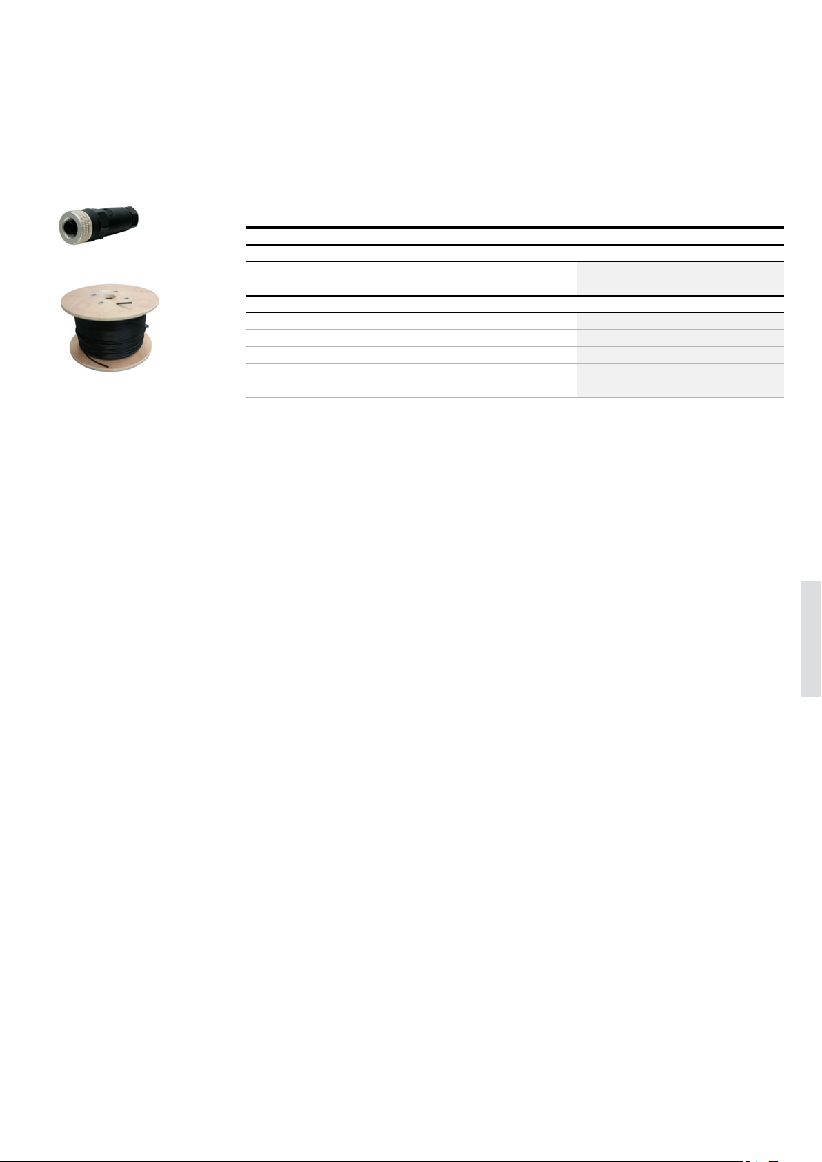
Separate cables and connectors
M12-C01
C5 cable
2TLC172657F0201
2TLC010038F0201
Description Typ e Order code
Connectors
M12-5 pole female, straight M12-C01 2TLA020055R1000
M12-5 pole male, straight M12-C02 2TLA020055R1100
Cable with 5 conductors
10 m cable with 5 x 0.34 shielded conductors C5 cable 10 m 2TLA020057R0001
50 m cable with 5 x 0.34 shielded conductors C5 cable 50 m 2TLA020057R0005
100 m cable with 5 x 0.34 shielded conductors C5 cable 100 m 2TLA020057R0010
200 m cable with 5 x 0.34 shielded conductors C5 cable 200 m 2TLA020057R0020
500 m cable with 5 x 0.34 shielded conductors C5 cable 500 m 2TLA020057R0050
6
Page 12
6– 1 2 SAFETY PRODUCTS CATALOG ABB JOKAB SAFETY
—
Technical data
Emergency stop buttons
Technical data
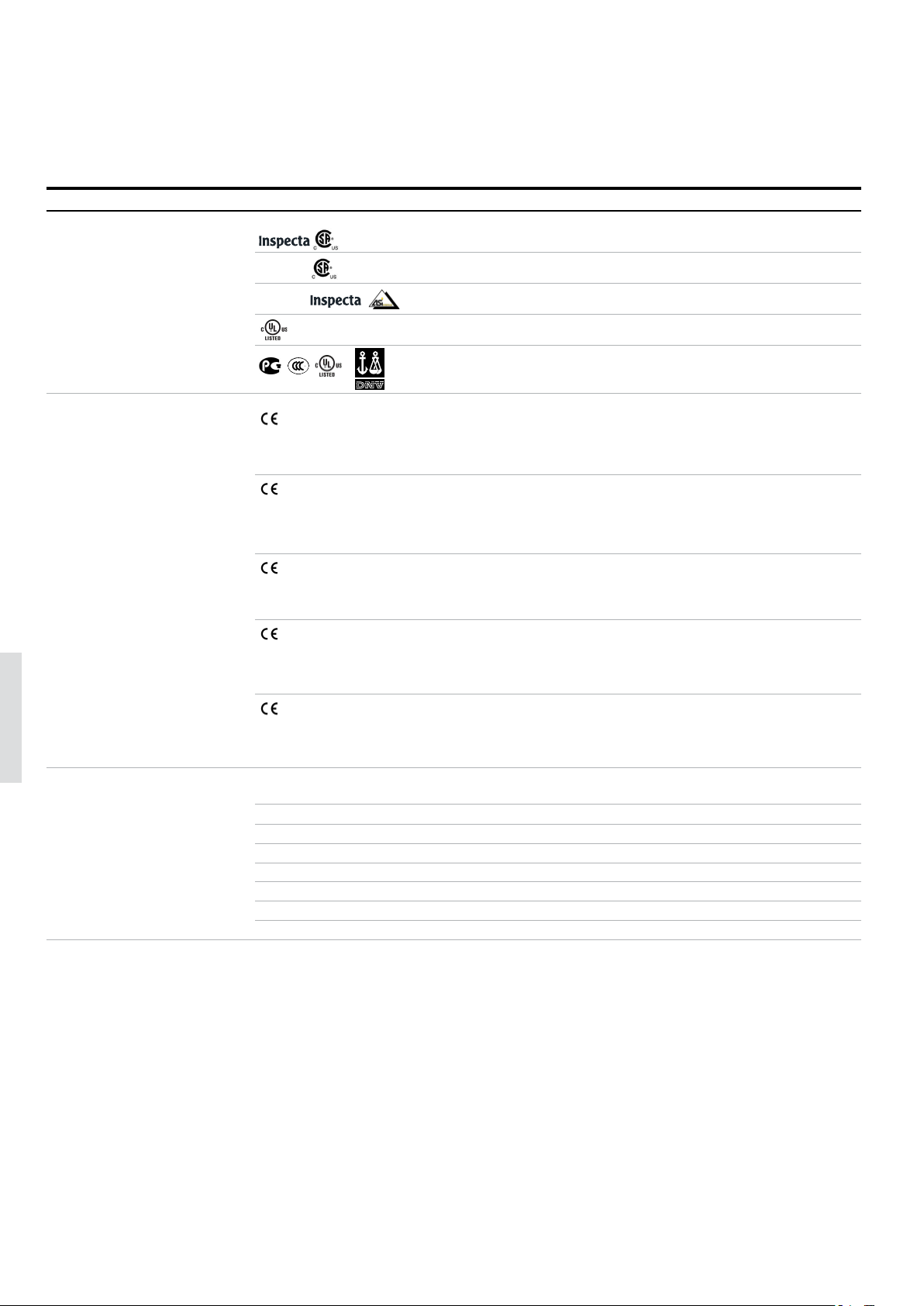
Approvals
Smile, INCA
Conformity
6
Functional safety data
Smile Tina, INCA Tina
Smile AS-i
EStrong
Compact
Smile, INCA
Smile Tina, INCA Tina
Smile AS-i
EStrong
Compact
EN 61508:2010 Up to SIL3, depending on system architecture
EN 62061:2005 Up to SILCL3, depending on system architecture
EN ISO 13849-1:2008 Up to Cat. 4, PL e, depending on system architecture
Smile, INCA B10
Smile Tina, INCA Tina PFH
Smile AS-i PFHD = 1.69 x 10
EStrong B10
Compact B10
TÜV NORD
TÜV NORD
2006/42/EC – Machinery
2011/65/EU - RoHS
EN ISO 12100:2010, EN ISO 13849-1:2008/AC:2009, EN 60204-1:2006+A1:2008, EN ISO 13850:2008
2006/42/EC - Machinery
2004/108/EC - EMC
EN ISO 12100:2010, EN ISO 13849-1:2008, EN 62061:2005, EN 60204-1:2006+A1:2009, IEC 60664-1:2007, EN 61000-6-2:2005, EN 61000-64:2007, EN 60947-5-5:2005, EN ISO 13850:2006
2006/42/EC - Machinery
EN ISO 12100:2010, EN ISO 13849-1:2008/AC:2009,EN ISO 13849-2:2012, EN 60204-1:2007+A1, EN ISO 13850:2008, IEC 60947-5-5:2005
2006/42/EG – Machinery
2011/65/EU - RoHS
EN ISO 12100:2010, EN ISO 13850:2015, EN 60204-1:2006:+A1:2009+AC:2010, EN 60947-5-5:1997:+A1:2017, EN 60947-5-1:2004:+A1:2009
2006/42/EC - Machinery
2014/30/EU - EMC
EN 60947-1:2007/A1:2011/A2:2014, EN 60947-5-1:2004/A1:2009, EN 60947-5-5:1997/A1:2005/A11:2013, EN ISO 13850:2008
= 100 000
d
= 4.66 x 10
D
= 1 500 000
d
= 250 000
d
-9
-9
Page 13

EMERGENCY STOPS AND PILOT DE VICES 6– 1 3
—
Technical data
Emergency stop buttons
Technical data
Electrical data
Operating voltage
Smile, INCA 17-27 VDC ± 10%
Smile Tina, INCA Tina +24 VDC +15% -25%
Smile AS-i +30 VDC from the AS-i bus. Tolerances 26.5 - 31.6 VDC
EStrong 230 VAC / +24 VDC (the LED is +24 VDC originally, but can be replaced with a 230 VAC accessory)
Compact 230 VAC / +24 VDC
Mechanical data
Mechanical life >50 000 operations
Operating temperature
Smile, INCA -10…+55 °C
EStrong -25…+80 °C
Compact -25…+70 °C
Protection class
Smile, INCA IP65
EStrong IP67, IP69K
Compact IP66, IP67, IP69K
Weight
Smile 65 g
INCA 45 g
EStrong 820 g
Compact 108 g, 124 g (with shroud)
Material
Smile Polyamide PA66, Macromelt, polybutylenterephthalate PBT, Polypropene PP, UL 94 V0
INCA Polyamide PA66, Macromelt, polybutylenterephthalate PBT, Polypropene PP, UL 94 V0
EStrong Stainless steel 316 housing
Compact Polycarbonate
6
More information
Fore more information, e.g. the complete technical information, see product manual for:
Smile 2TLC172097M0201
INCA 2TLC172163M0201
EStrong 2TLC172247M0201
Compact 1SFC151005C0201
Page 14
6– 14 SAFETY PRODUCTS CATALOG ABB JOKAB SAFETY
—
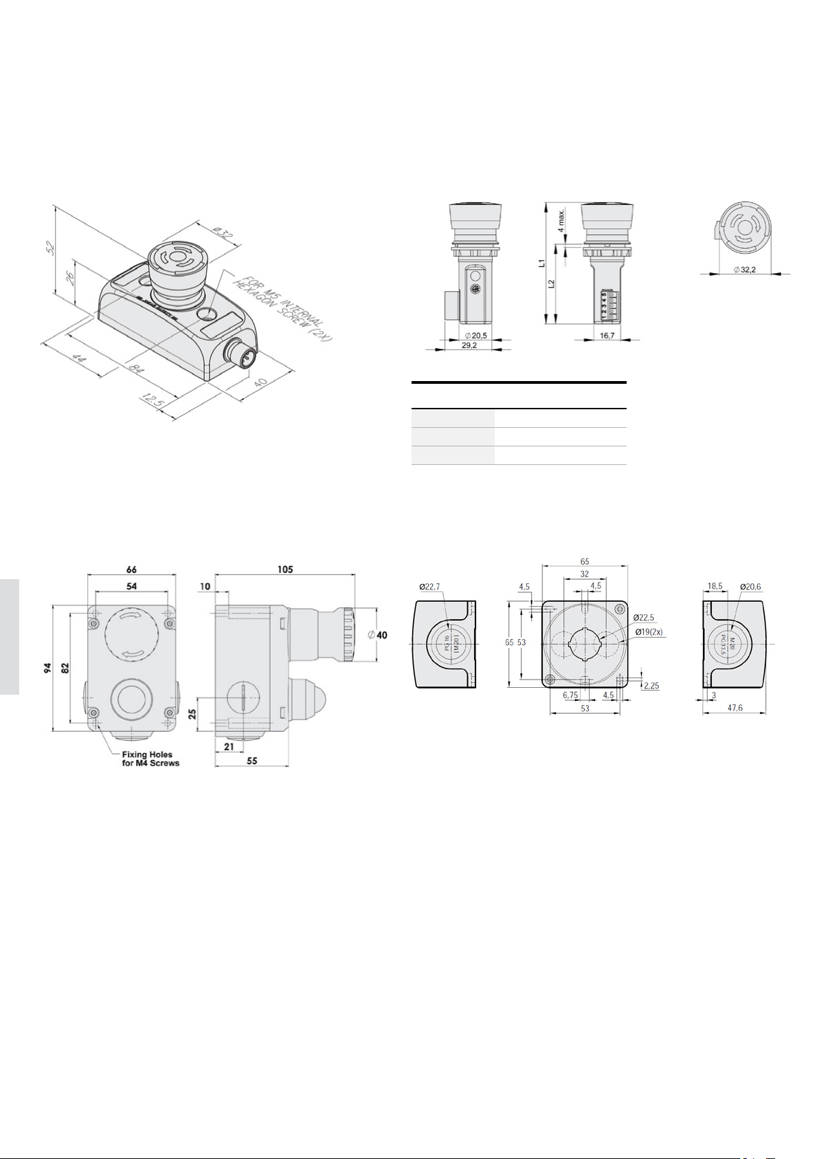
Dimension drawings
Emergency stop buttons
Smile
INCA
Typ e L1
mm
INCA 1 EC Tina 75.5 49.5 ± 0.5
INCA 1 80 54 ± 0.5
INCA 1 Tina 80 54 ± 0.5
EStrong Compact (housing only)
L2
mm
6
All dimensions in mm
Page 15

EMERGENCY STOPS AND PILOT DE VICES 6– 1 5
6
Page 16
6– 16 SAFETY PRODUCTS CATALOG ABB JOKAB SAFETY
—
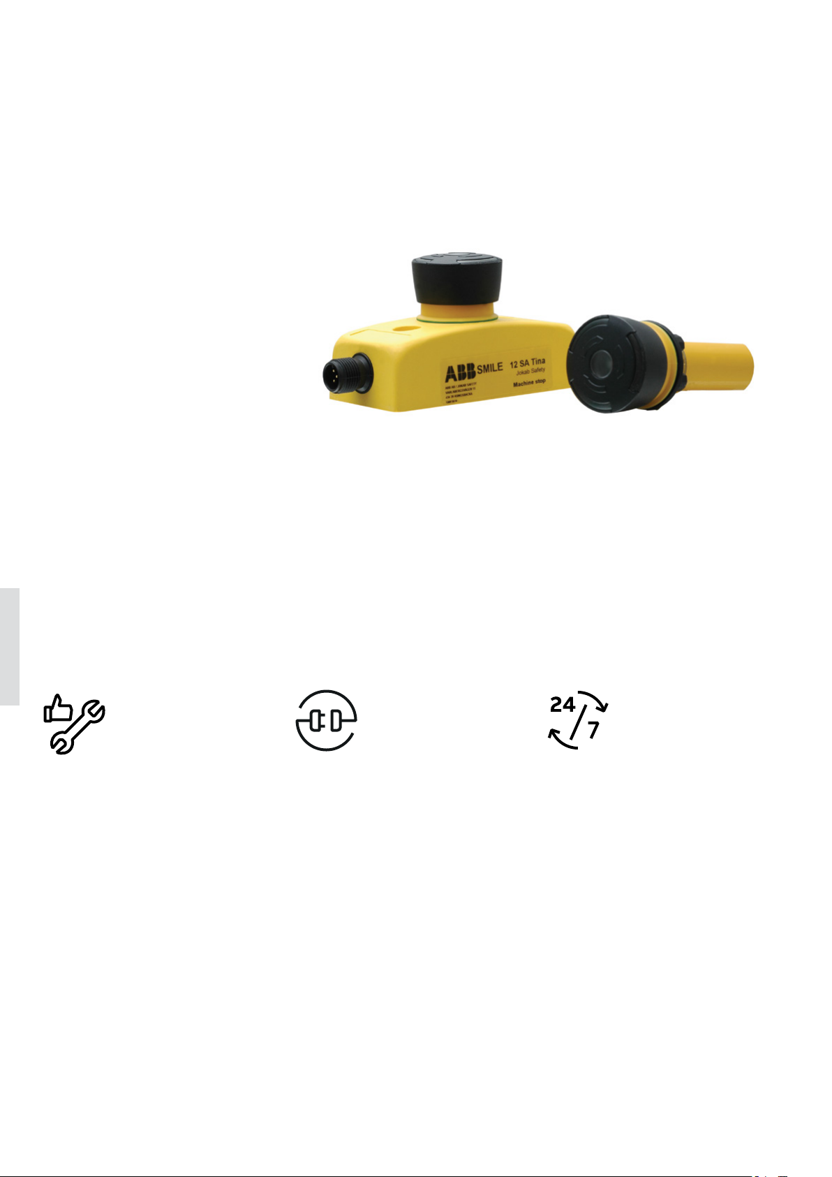
Safety stop buttons
Smile, INCA and Compact
Safety stop buttons are used to safely
stop a certain part of a dangerous
machine.
ABB offers safety stop buttons to suit
different needs of connection and
communication. Models are available
for e.g. external mounting or panel
mounting, in compact size or robust
design, adapted for the DYNlink solution or with 2 NC contacts.
6
Easy to install
Compact size
Models with a compact and appealing
housing saves space and makes it easy
to place.
Quick installation
Quick and easy installation of models
with features such as centered mounting holes, removable terminal blocks
and M12 connectors.
Optimum interface
Highly adaptable
Several models to choose between
depending on position, installation
and function.
Reliable in extreme conditions
Robust models for use in demanding
environments.
Continuous operation
LED diagnostics
Models with integrated LED diagnostics reduce downtime when troubleshooting.
Serial connection
Tina models save cable length and installation time with serial connection.
Page 17
EMERGENCY STOPS AND PILOT DE VICES 6 – 17
—
Applications and features
Safety stop buttons
Applications
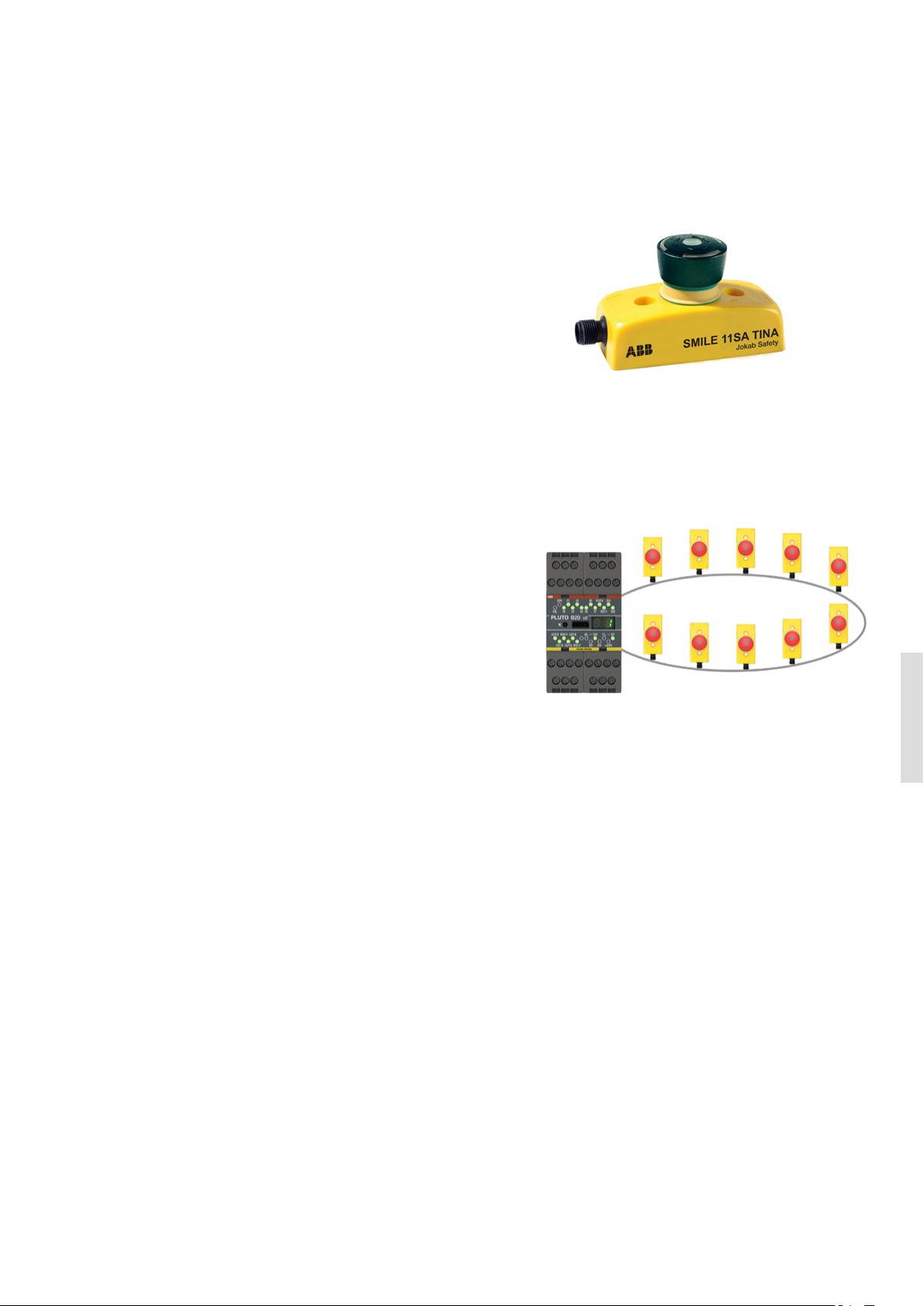
A safety stop (also called machine stop) can be used to safely
stop a part of the machine, e.g. as a stop for an individual
hazardous machine function. It may not be used as an emergency stop and stop the complete machine or production line.
Likewise, an emergency stop with red push button should not
be used as a safety stop. In order to separate the safety stop
function from the emergency stop function, the safety stop
buttons should be colored black.
Features
DYNlink
Safety stop buttons with Tina in their name belong to the DYNlink solution, which enables serial connection using only one
channel and still reaching Cat. 4/PL e. DYNlink devices must be
used with Vital safety controller or Pluto programmable safety
controller. Up to 30 DYNlink devices can be connected in series
to Vital and up to 10 can be connected to each input on Pluto.
6
Page 18
6– 1 8 SAFETY PRODUCTS CATALOG ABB JOKAB SAFETY
—
Models
Safety stop buttons
Safety stop buttons for external mounting
Smile
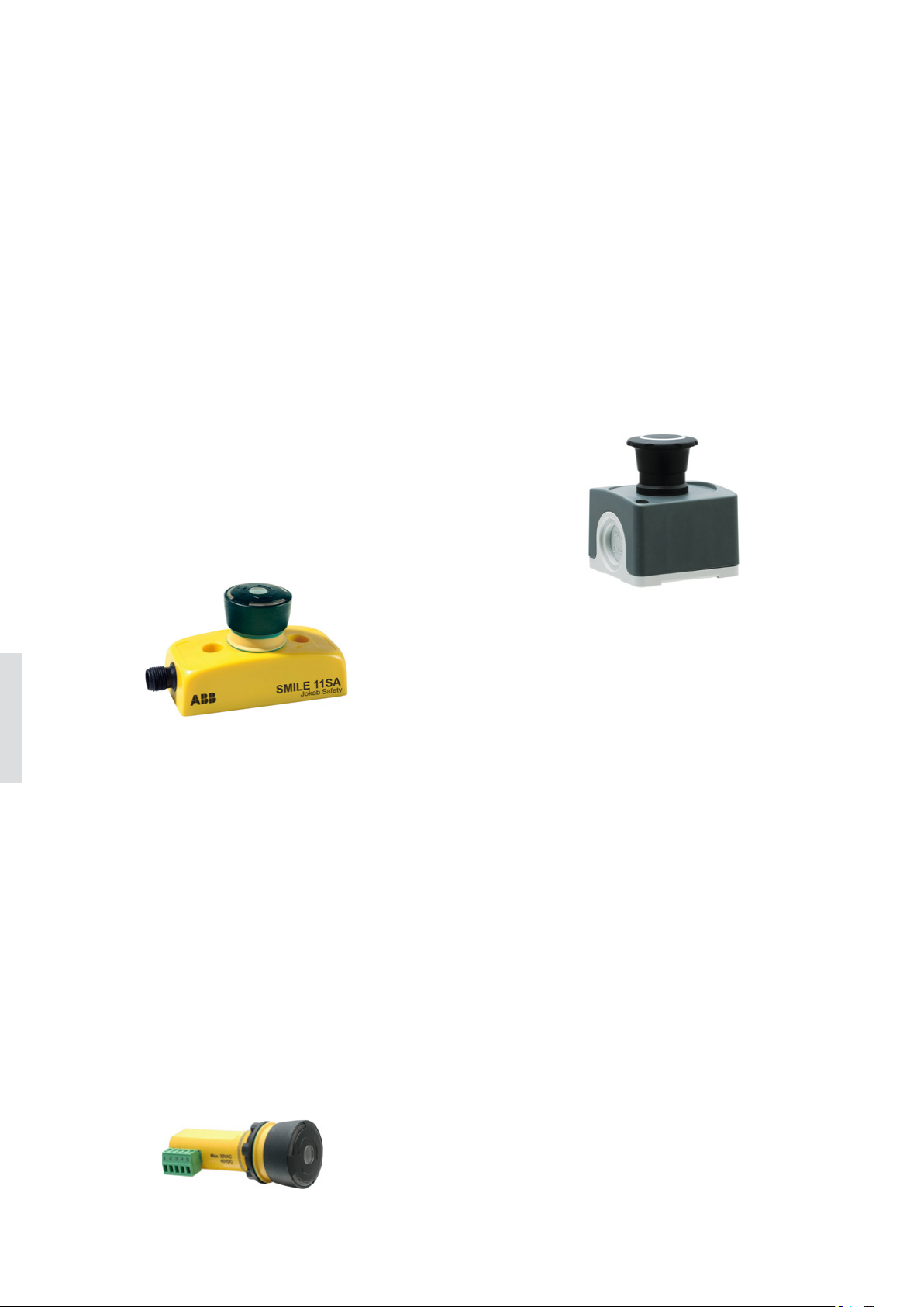
Smile is a small and easy to install safety stop button. Its
size allows mounting in reduced spaces, and its centered
mounting holes makes it especially easy to mount on aluminum extrusions (e.g. Quick-Guard fencing system).
Smile has an integrated LED in the button that shows the
status and simplifies error tracking.
The standard model of Smile has 2 contacts and can be
used with safety controllers from all brands. The Smile
Tina model belongs to the ABB DYNlink solution, with the
advantages of serial connection using only one channel and
still reaching Cat. 4/PL e.
Smile safety stops are identical to the corresponding Smile
emergency stops apart from the color of the button.
Compact
The Compact safety stop button offers a robust enclosure
with a high IP rating that fulfills the demands in severe and
humid environments, such as food and beverage industry.
Compact can be fitted with a Tina adapter for use in a DYNlink solution (Tina 2A, Tina 2B or Tina 3A).
Compact safety stop is identical to Compact emergency
stop apart from the color of the button.
6
Safety stops for panel mounting
INCA
INCA is a safety stop button for panel mounting, designed
for installation in 22.5 mm holes. Its removable terminal
block facilitates connection and exchange.
INCA has an integrated LED in the button that shows the
status and simplifies error tracking.
The standard model of INCA has 2 contacts and can be used
with safety controllers from all brands. INCA Tina belongs to
the ABB DYNlink solution, with the advantages of serial connection using only one channel and still reaching Cat. 4/PL e.
INCA safety stop is identical to INCA emergency stop apart
from the color of the button.
Page 19
EMERGENCY STOPS AND PILOT DE VICES 6– 19
—
Ordering information
Safety stop buttons
2TLC172198F0201
Smile 11 SA Tina
CEP1-1002
—
Safety stop buttons
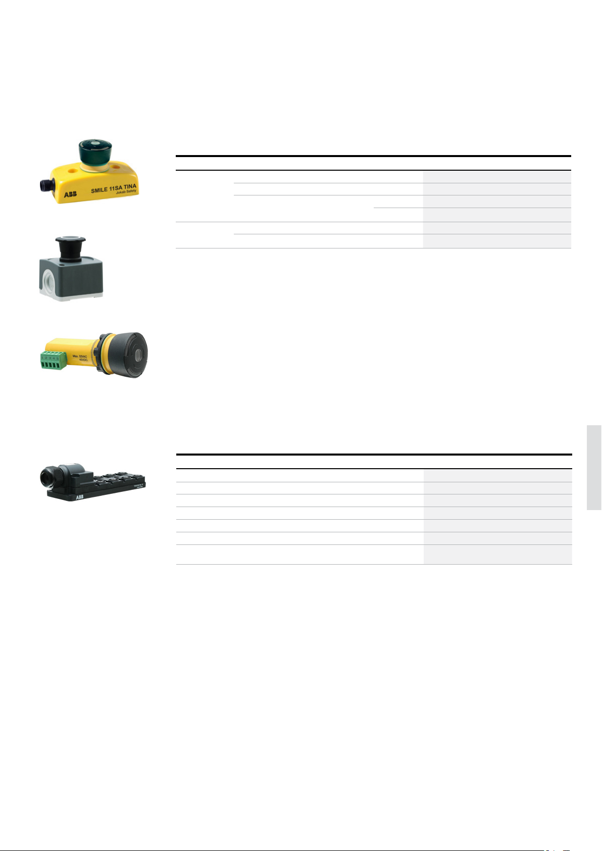
Mounting Type of safety signal Connection type Feature Ty pe Order code
External DYNlink 1 m cable from bottom Status LED Smile 11 SA Tina 2TLA030050R0500
2 NC 1 x M12-5 Status LED Smile 11 SA 2TLA030051R0900
2 NC* 2 x M20 conduits - CEP1-1002 (Compact) 1SFA619811R1002
With shroud CEP1-2002 (Compact) 1SFA619811R2002
Panel DYNlink 5 pole terminal block Status LED INCA 1S Tina 2TLA030054R0200
2 NC 5 pole terminal block Status LED INCA 1S 2TLA030054R0300
* Can be adapted to DYNlink with Tina
INCA 1S
Tina 8A
2TLC172365F0201
—
Accessories
Description Typ e Order code
M12 Y-connector for serial connection of devices without StatusBus functionality. M12-3A 2TLA020055R0000
Connection block for the serial connection of up to 4 DYNlink devices with 12-5 connectors. Tina 4A 2TLA020054R0300
2TLC172471F0201
Connection block for the serial connection of up to 8 DYNlink devices with 12-5 connectors. Tina 8A 2TLA020054R0500
Grey shroud for Compact CA1-8054 1SFA619920R8054
Adaptation unit for DYNlink solution with M20 fitting. For e.g. Compact. Tina 2A * 2TLA020054R0100
Adaptation unit for DYNlink solution, internal assembly. For e.g. Compact. Tina 2B * 2TLA020054R1100
Adaptation unit for DYNlink solution with M20 fitting and M12 connector. For e.g. connect-
ing Compact to Pluto/Vital.
* For more information about Tina adapter units, please see Pluto and Vital chapters.
Tina 3A * 2TLA020054R0200
6
Page 20
6– 2 0
SAFETY PRODUCTS CATALOG ABB JOKAB SAFETY
—
Cable and connectors
Safety stop buttons
2TLC172951F0201
M12-C61
2TLC010003F0201
M12-C61HE
—
Cable with connectors
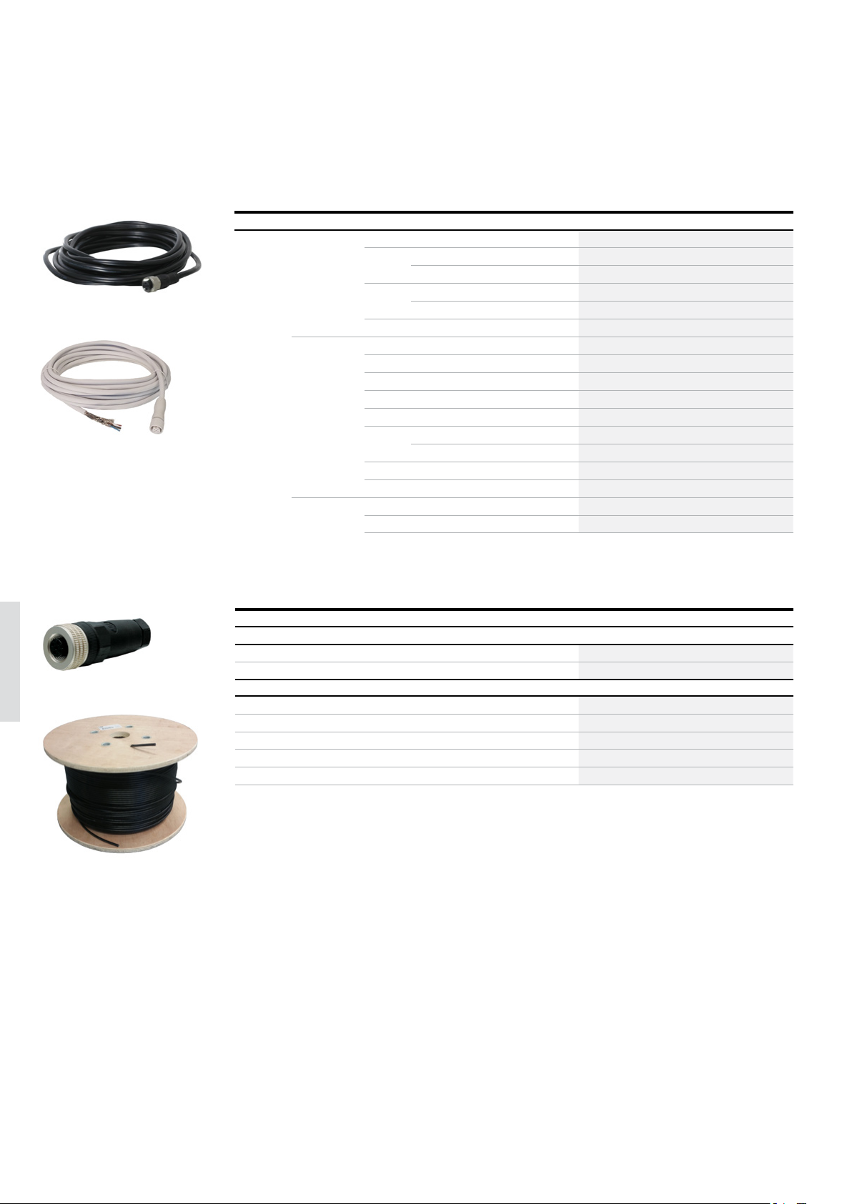
Connector Female/male Length Special feature Type Order code
M12-5 Female 3 m M12-C31 2TLA020056R0500
6 m M12-C61 2TLA020056R0000
Harsh environment, halogen free M12-C61HE 2TLA020056R8000
10 m M12-C101 2TLA020056R1000
Harsh environment, halogen free M12-C101HE 2TLA020056R8100
20 m M12-C201 2TLA020056R1400
Female + male 0.3 m M12-C0312 2TLA020056R5800
0.06 m M12-C00612 2TLA020056R6300
1 m M12-C112 2TLA020056R2000
3 m M12-C312 2TLA020056R2100
6 m M12-C612 2TLA020056R2200
10 m M12-C1012 2TLA020056R2300
Angled female connector M12-C1012V2 2TLA020056R6700
16 m M12-C1612 2TLA020056R5400
20 m M12-C2012 2TLA020056R2400
Male 6 m M12-C62 2TLA020056R0200
10 m M12-C102 2TLA020056R1200
—
Separate cables and connectors
Description Typ e Order code
Connectors
6
2TLC172657F0201
M12-C01
C5 cable
M12-5 pole female, straight M12-C01 2TLA020055R1000
M12-5 pole male, straight M12-C02 2TLA020055R1100
Cable with 5 conductors
10 m cable with 5 x 0.34 shielded conductors C5 cable 10 m 2TLA020057R0001
50 m cable with 5 x 0.34 shielded conductors C5 cable 50 m 2TLA020057R0005
100 m cable with 5 x 0.34 shielded conductors C5 cable 100 m 2TLA020057R0010
200 m cable with 5 x 0.34 shielded conductors C5 cable 200 m 2TLA020057R0020
500 m cable with 5 x 0.34 shielded conductors C5 cable 500 m 2TLA020057R0050
2TLC010038F0201
Page 21
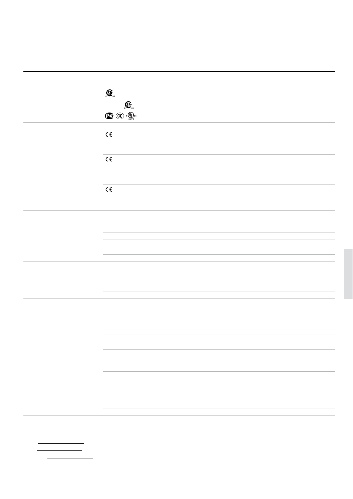
EMERGENCY STOPS AND PILOT DE VICES 6 – 21
—
Technical data
Safety stop buttons
Technical data
Approvals
Smile, INCA
Smile Tina, INCA Tina
Compact
Conformity
Smile, INCA
Smile Tina, INCA Tina
Compact
Functional safety data
EN 61508:2010 Up to SIL3, depending on system architecture
EN 62061:2005 Up to SILCL3, depending on system architecture
EN ISO 13849-1:2008 Up to Cat. 4, PL e, depending on system architecture
Smile, INCA B10
Smile Tina, INCA Tina PFH
Compact B10d = 50 000
Electrical data
Operating voltage
Smile, INCA 17-27 VDC ± 10%
Smile Tina, INCA Tina +24 VDC +15% -25%
Compact 230 VAC / +24 VDC
Mechanical data
Mechanical life >50 000 operations
Operating temperature
Smile, INCA -10…+55 °C
Compact -25…+70 °C
Protection class
Smile, INCA IP65
Compact IP66, IP67, IP69K
Weight
Smile 65 g
INCA 45 g
Compact 108 g, 124 g (with shroud)
Material
Smile Polyamide PA66, Macromelt, polybutylenterephthalate PBT, Polypropene PP, UL 94 V0
INCA Polyamide PA66, Macromelt, polybutylenterephthalate PBT, Polypropene PP, UL 94 V0
Compact Polycarbonate
TÜV NORD
2006/42/EC – Machinery
2011/65/EU - RoHS
EN ISO 12100:2010, EN ISO 13849-1:2008/AC:2009, EN 60204-1:2006+A1:2008, EN ISO 13850:2008
2006/42/EC - Machinery
2004/108/EC - EMC
EN ISO 12100:2010, EN ISO 13849-1:2008, EN 62061:2005, EN 60204-1:2006+A1:2009, IEC 60664-1:2007,
EN 61000-6-2:2005, EN 61000-6-4:2007, EN 60947-5-5:2005, EN ISO 13850:2006
2006/42/EC - Machinery
2014/30/EU - EMC
EN 60947-1:2007/A1:2011/A2:2014, EN 60947-5-1:2004/A1:2009, EN 60947-5-5:1997/A1:2005/A11:2013, EN ISO 13850:2008
= 100 000
d
= 4.66 x 10
D
-9
6
More information
Fore more information, e.g. the complete technical information, see product manual for:
Smile 2TLC172097M0201
INCA 2TLC172163M0201
Compact 1SFC151005C0201
Page 22
6– 2 2 SAFETY PRODUCTS CATALOG ABB JOKAB SAFETY
—
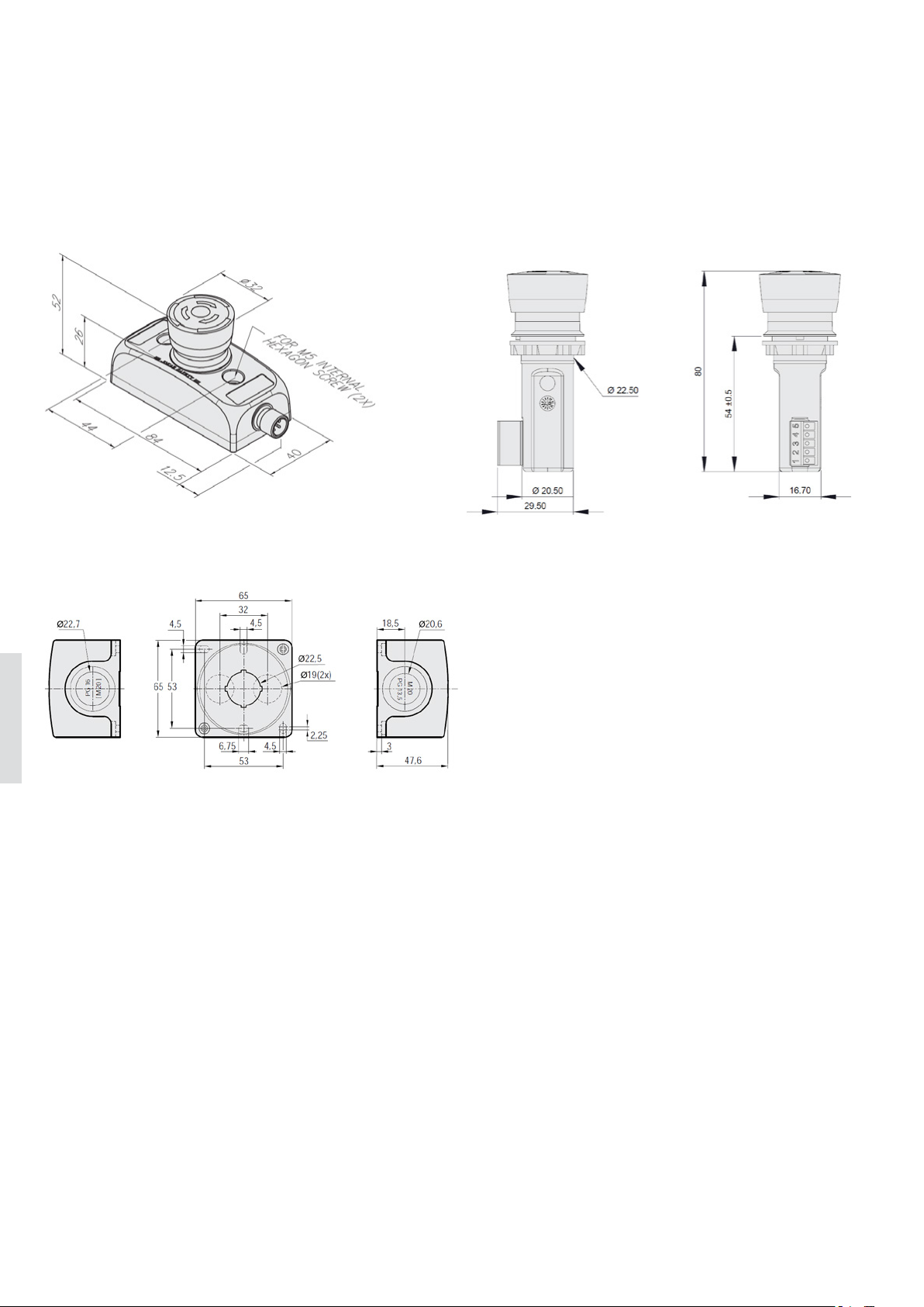
Dimension drawings
Safety stop buttons
Smile
Compact (housing only)
INCA
6
All dimensions in mm
Page 23

EMERGENCY STOPS AND PILOT DE VICES 6– 23
6
Page 24
6– 24 SAFETY PRODUCTS CATALOG ABB JOKAB SAFETY
—
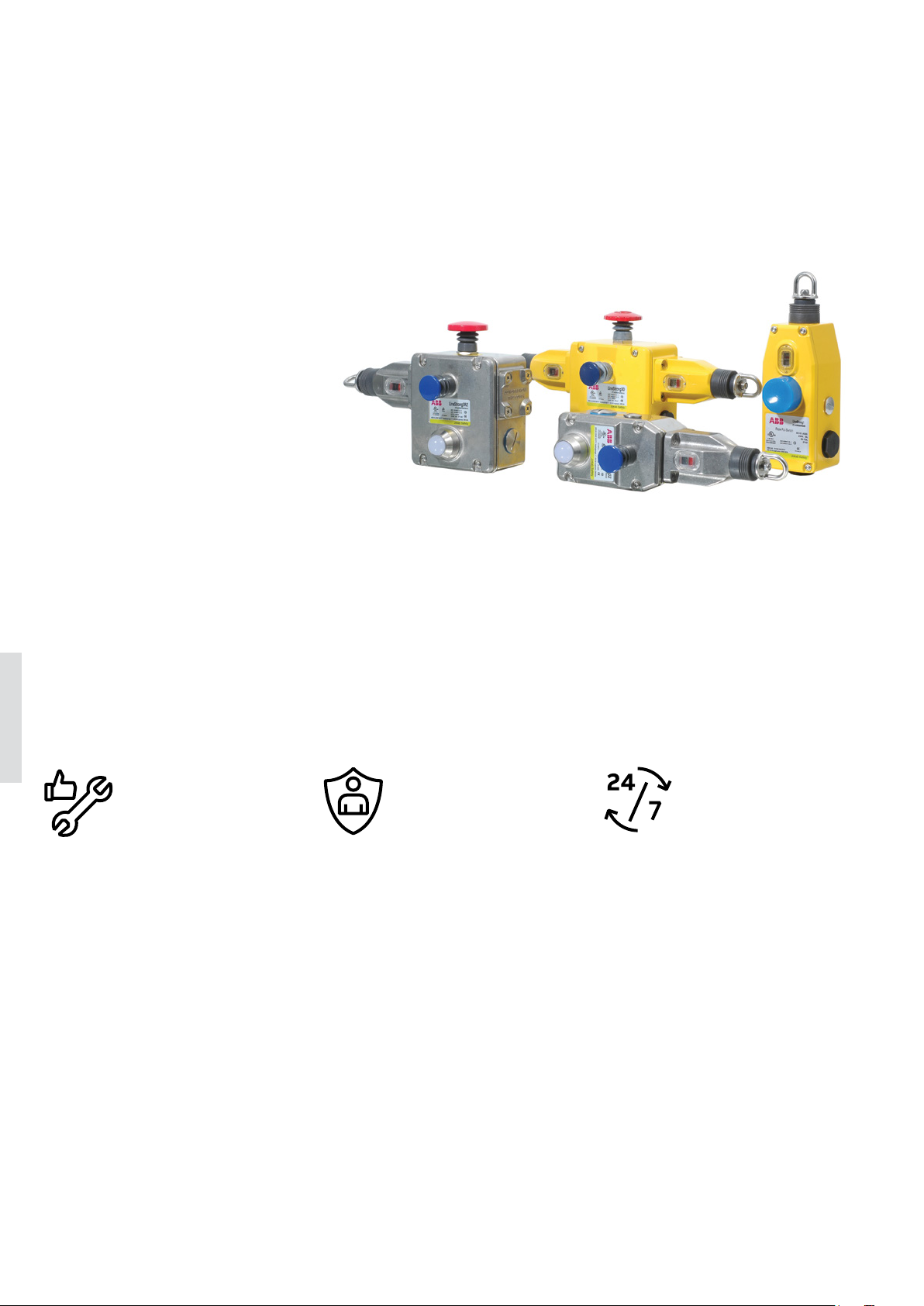
Pull wire emergency stop switch
LineStrong
LineStrong is a pull wire emergency
stop switch, used for easy reach of
the emergency stop function along
machines and sections of conveyors.
A pull wire emergency stop switch
allows to initiate the emergency stop
command from any point along the installed wire length by pulling the wire.
It replaces a series of emergency stop
buttons and is easier to install.
LineStrong is also available in different models for different lengths of
wires, with different housing material
as well as an explosion proof version.
6
Quick installation
A pull wire emergency stop switch is
easier to install than a system of several emergency stop buttons along a
carriage path.
Highly adaptable
Several models to choose between
gives a variety of mounting possibilities and features.
Long wire length
Can handle wires up to 200 m on a
single switch.
Safety and protectionEasy to install
Easily accessible
Easy reach of the emergency stop
function along machines, conveyors
and processes.
High level of safety
The positive forced disconnect contacts provide a high level of safety
and are double switching, i.e. triggers
emergency stop in both directions of
the wire.
Continuous operation
Reliable in extreme conditions
Robust construction makes LineStrong
ideal for use in demanding environments.
LED diagnostics
Integrated LED diagnostics ensures
status can be seen easily from a distance.
Page 25
—
Applications
LineStrong
EMERGENCY STOPS AND PILOT DE VICES 6– 2 5
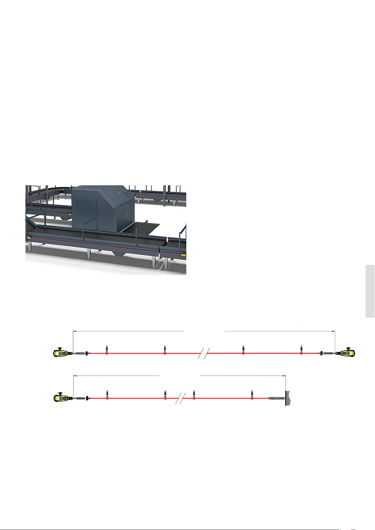
Instead of multiple emergency stops
A pull wire emergency stop switch is often placed along
conveyor belts or carriage paths where access to the stop
function must be possible along the whole line. It is often
easier to install a pull wire emergency stop switch than to
place multiple emergency stop buttons if the distance is
longer.
LineStrong can handle wires up to 200 m on one single
switch and since the emergency stop command can be
initiated from any point along the wire, this gives better access to the emergency stop function than using emergency
stop buttons.
As protective device in low risk applications
LineStrong can be used as protection, for example along
conveyors with low risks where the wire can be installed
at waist height in front of the conveyor, which provides an
emergency stop if someone walks or falls towards the conveyor, hence pulling the wire.
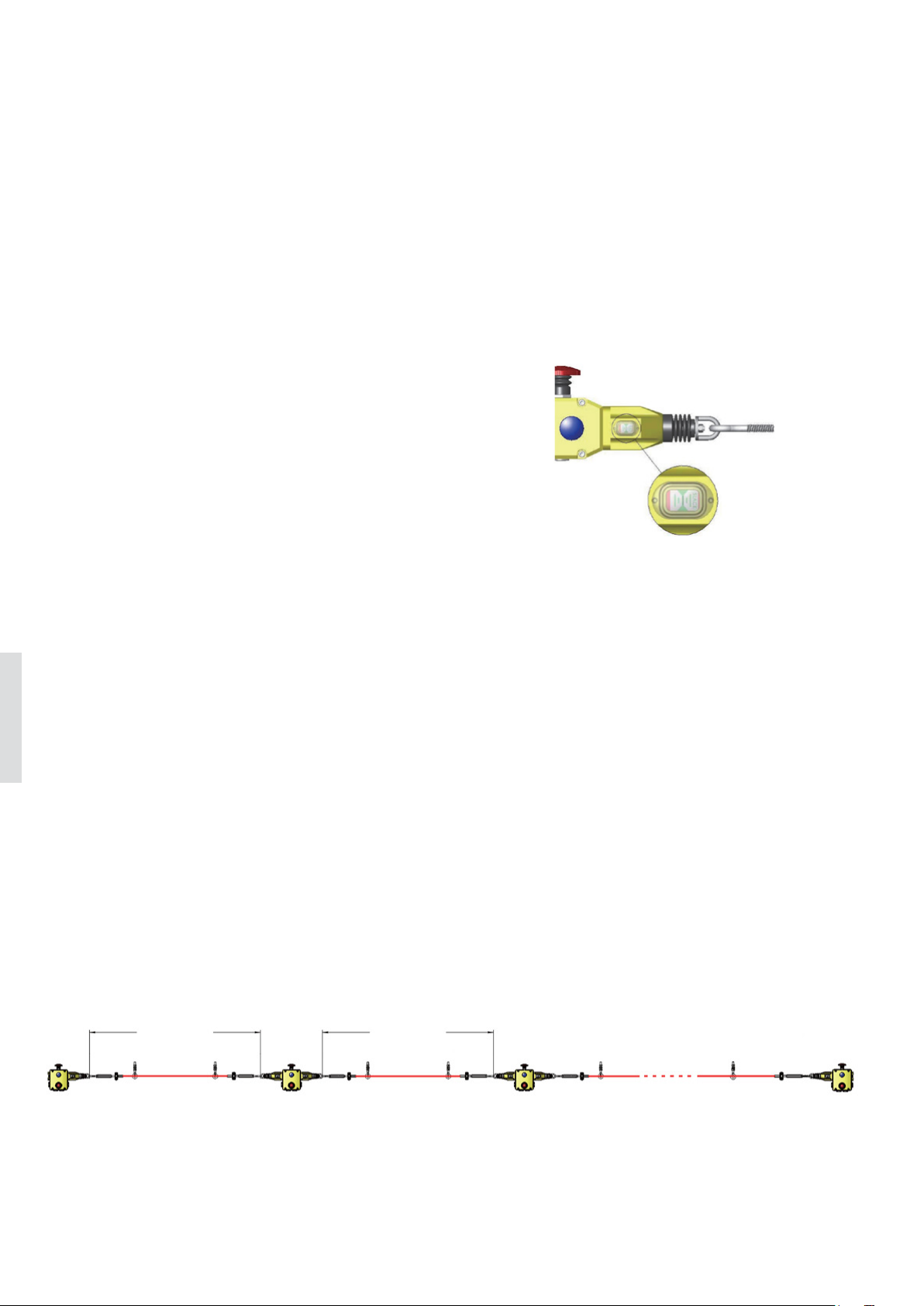
One, two or several switches
The maximum length of the wire attached to LineStrong depends on if there is a LineStrong unit attached to both ends
of the wire or if one end is attached to a wall/fixed object. In
the image below LineStrong2 is used as an example.
Two units
Up to 60 m
One unit
6
Up to 80 m
Page 26
6– 2 6
—
Features
LineStrong
SAFETY PRODUCTS CATALOG ABB JOKAB SAFETY
Positive forced disconnected contacts
The contacts in LineStrong are positive force disconnected,
which ensures that the contacts will not be held in a normally closed position due to a failure of the spring mechanism
or the welding/sticking of the contacts.
Reset button
All models of LineStrong have an integrated reset button
that needs to be pressed in order to reset the emergency
stop if the emergency stop function has been triggered.
Emergency stop button
Most LineStrong models have an integrated emergency stop
button on the housing of the switch. Since the first half meter of the wire is not intended to pull in order to trigger the
emergency stop function, the integrated emergency stop
button provides quick and simple access to the emergency
stop function if you are standing right in front of LineStrong.
The emergency stop button of LineStrong 2 can be moved to
either side of LineStrong to enable best access depending
on position and height of LineStrong.
Integrated LED
LineStrong2 and LineStrong3 have an integrated 2-color LED
that shows if the emergency stop function has been triggered or not. The LED is also available as spare part.
6
Material
LineStrong is available with a housing in yellow die cast
aluminum alloy or with a housing in stainless steel 316 which
is recommended for severe applications in e.g. the food processing and the chemical industries.
Wire breakage monitoring
The contacts are double switching which means that the
emergency stop command is given both when someone
pulls the wire and if the wire should break.
Indication of wire tension
All models are equipped with an indicator of the tension of
the wire which simplifies installation and adjustment.
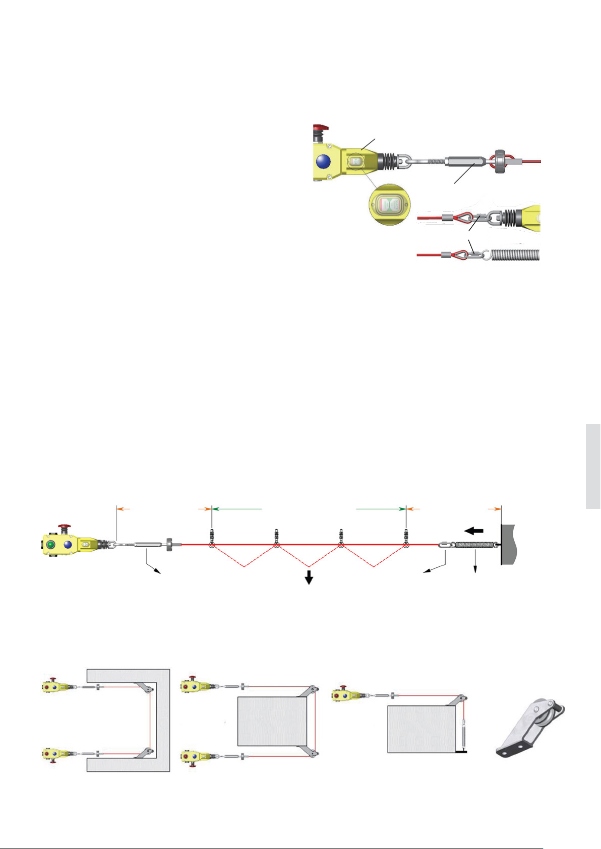
Left hand, right hand or both sides
LineStrong1 and LineStrong2 can be mounted in any direction. Linestrong3 is available in different models depending
on installation. L (left hand) should be used if the placement
of the grab wire switch is to the left in the installation. R
(right hand) should be used if the grab wire switch is to the
right in the installation. D (double wire) has wire entries
from both sides of the grab wire switch.
Up to 125 m Up to 125 m
Left Double Double Right
Page 27
EMERGENCY STOPS AND PILOT DE VICES 6 – 27
—
Features
LineStrong
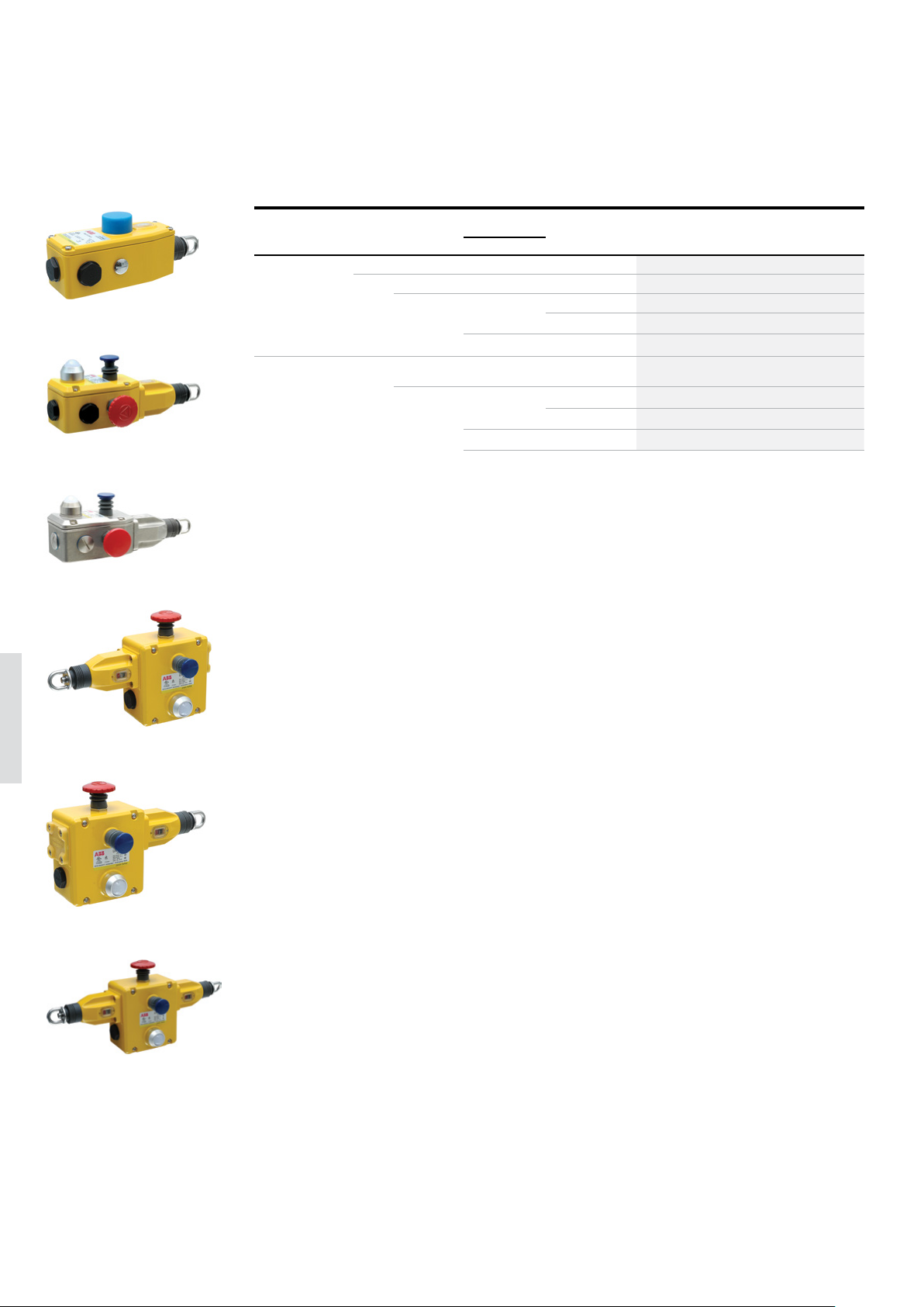
Easier installation with tensioner/gripper
The tensioner/gripper accessory significantly reduces the
installation time. Traditional grab wire systems normally
need turnbuckle and clamps, which are difficult to tension
and adjust, and normally require frequent re-tensioning.
The tensioner gripper integrates an eyehook, a tensioner
thimble and a wire strength gripper in one assembly which
enables rapid connection to the switch eyebolts and fast
and accurate tensioning of the wire.
Thanks to the switch tension indicator, it is easy to adjust the system accurately and quickly. The double clamp
mechanism prevents wire slippage and significantly reduces
machine downtime which can occur which traditional turnbuckle systems.
For systems longer than 50 m, the tensioner/gripper is necessary on both sides.
1
2
3
2
1. Tension to mid position as indicated by the green arrows in the
viwing window of each switch
2. The tensioner thimble allows immediate accurate and final tensioning of the wire, whilst viewing the tension marker through the
viewing window on the switch.
3. Quick Link termination.
Quick-link termination
The quick link termination is available as an accessory in the wire pull kit, for easy connection to the safety spring or the
switch eyebolt for systems up to 50 m.
Mounting accessories
The wire pull kits contains the suitable accessories for the included wire length.
- When using one switch, the wire must be anchored at the other end using a safety spring.
- The first eyeball support must be placed no more than 500 mm from the switch eyebolt or safety spring.
- The part of the wire from the wire end to the first eyebolt support shall not be used as part of the active protection coverage.
- Wire support eyebolts must be fitted at 2.5 - 3 meters intervals along the complete wire length.
- The tensioner/gripper is used to adjust the correct tension
Inactive zone
(500mm)
Tensioner / Gripper Pull Quick link Safety spring
Zone of protection
Eyebolt
Wire
Inactive zone
(500mm)
Corner pulley
A corner pulley can be used to navigate inside or outside corners without causing damage to the wire. They are in stainless
steel and can be rigidly mounted.
When using a safety spring, a maximum of one corner pulley may be used, to ensure that the complete length of the wire is
visible from either the switch or the spring anchorage.
6
Machine
Inside
corners
Machine
Examples of using the corner pulley
Machine
Outside
corners
Machine
Outside
corners
Machine
Corner pulley
Page 28
6– 2 8
SAFETY PRODUCTS CATALOG ABB JOKAB SAFETY
—
Ordering information
LineStrong
—
LineStrong
LineStrong1
LineStrong2
LineStrong2Z
2TLC172377F0201
2TLC172379F0201
2TLC172501F0201
IP rating Material E-stop
button
IP67 Yellow
die cast
alumi-
No 2 NO + 2 NC 30 50 - LineStrong1 2TLA050200R0030
Yes 2 NO + 2 NC 60 80 - LineStrong2 2TLA050202R0332
num
alloy
IP67, IP69K Stainless
Yes 2 NO + 2 NC 80 100 - LineStrong2Z 2TLA050202R0322
steel 316
Contacts Max. wire
Feature Type Order code
length (m)
1 unit 2 units
2 NO + 4 NC 100 125 Left hand LineStrong3L 2TLA050206R0332
Right hand LineStrong3R 2TLA050208R0332
200 325 Both sides LineStrong3D 2TLA050204R0332
2 NO + 4 NC 100 125 Left hand LineStrong3LZ 2TLA050206R0322
Right hand LineStrong3RZ 2TLA050208R0322
200 325 Both sides LineStrong3DZ 2TLA050204R0322
6
2TLC172385F0201
LineStrong3L
2TLC172387F0201
LineStrong3R
2TLC172383F0201
LineStrong3D
Page 29
—
Accessories
LineStrong
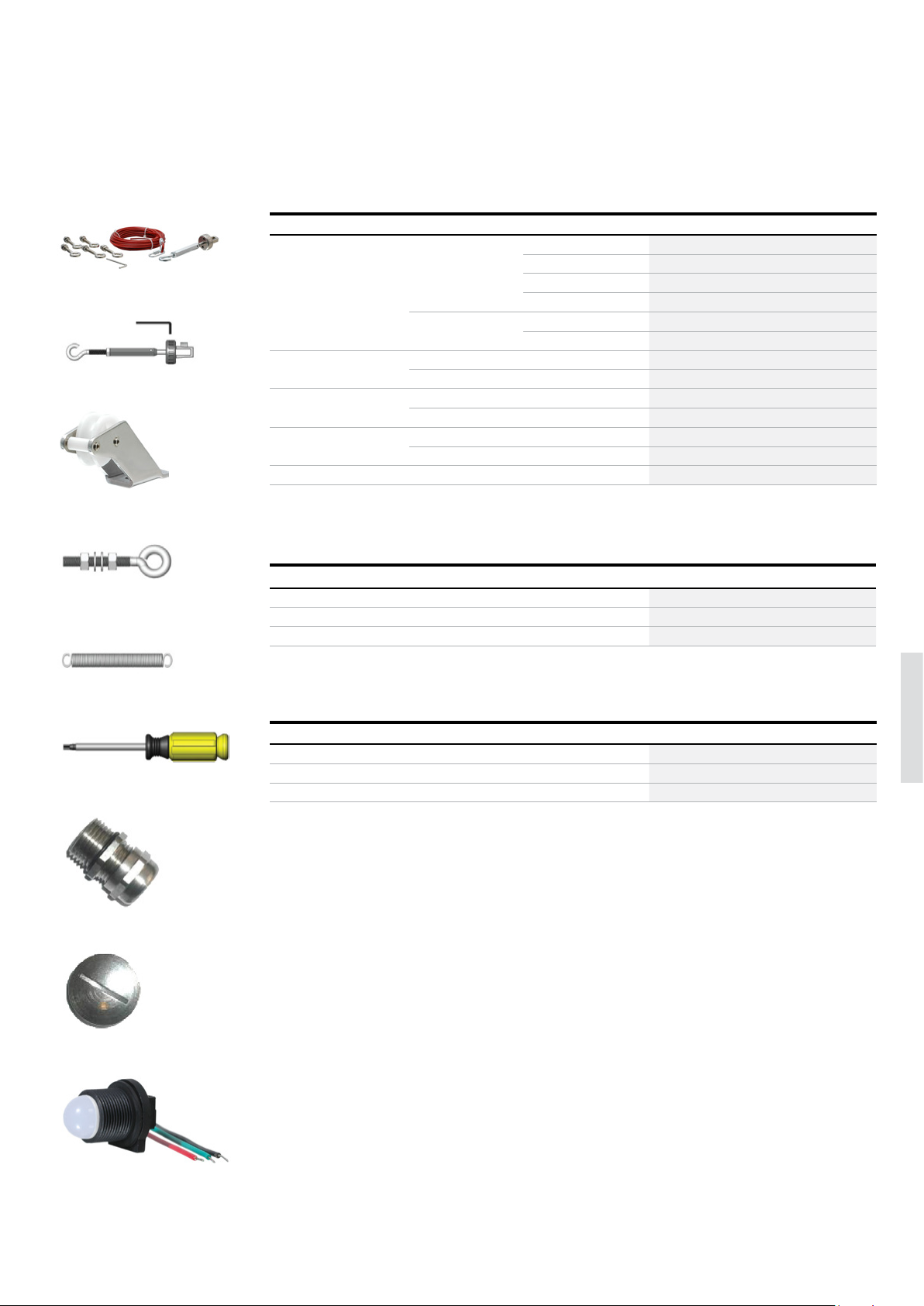
Wire pull kit
Wire tensioner
EMERGENCY STOPS AND PILOT DE VICES 6– 2 9
—
Mounting Accessories
Description Material Length Type Order code
Wire pull kit including wire,
eyebolts, tensioner/gripper,
2TLC172577F0201
quick-link and Allen key in right
quantity for the included wire
length.
Galvanized 10 m wire 10 m wire kit, gal 2TLA050210R0130
20 m wire 20 m wire kit, gal 2TLA050210R0330
80 m wire 80 m wire kit, gal 2TLA050210R0630
100 m wire 100 m wire kit, gal 2TLA050210R0730
Stainless steel 50 m wire 50 m wire kit, SS 2TLA050210R0520
100 m wire 100 m wire kit, SS 2TLA050210R0720
2TLC172220F0201
Wire tensioner/gripper Galvanized Wire tensioner, gal 2TLA050210R4030
Stainless steel Wire tensioner, SS 2TLA050210R4020
Corner pulley Galvanized Corner pulley, gal 2TLA050210R6030
Stainless steel Corner pulley, SS 2TLA050210R6020
Eyebolt M8 x 1.25 (8 pcs)
Galvanized Eyebolt M8x1.25, gal 2TLA050210R8030
Stainless steel Eyebolt M8x1.25, SS 2TLA050210R8020
Safety spring, 220mm Stainless steel Spring 220 mm, SS 2TLA050211R0004
Corner pulley
Eyebolt
Safety spring
LineStrong Screwdriver
Gland
2TLC172219F02012TLC172221F0201 2TLC172581F0201
2TLC172217F0201
—
Other accessories
Description Typ e Order code
Screwdriver, anti-tamper, Torx T20 Screwdriver T20 2TLA050211R0006
Gland M20 x 1.5 Gland M20x1.5 2TLA050040R0002
Conduit plug M20 x 1.5 Cond.Plug M20x1.5 2TLA050040R0004
—
Spare parts
Description Typ e Order code
LineStrong LED Green/Red +24 VDC LineStrong LED 24 2TLA050211R0001
2TLC172215F0201
LineStrong LED Green/Red 230 VAC LineStrong LED 230 2TLA050211R0003
LineStrong2 and LineStrong3 Emergency stop button. LineStrong E-Stop 2TLA050211R0005
6
Conduit plug
LineStrong LED 230
LineStrong LED 230
2TLC172218F0201
2TLC172902F0201
Page 30
6– 3 0
—
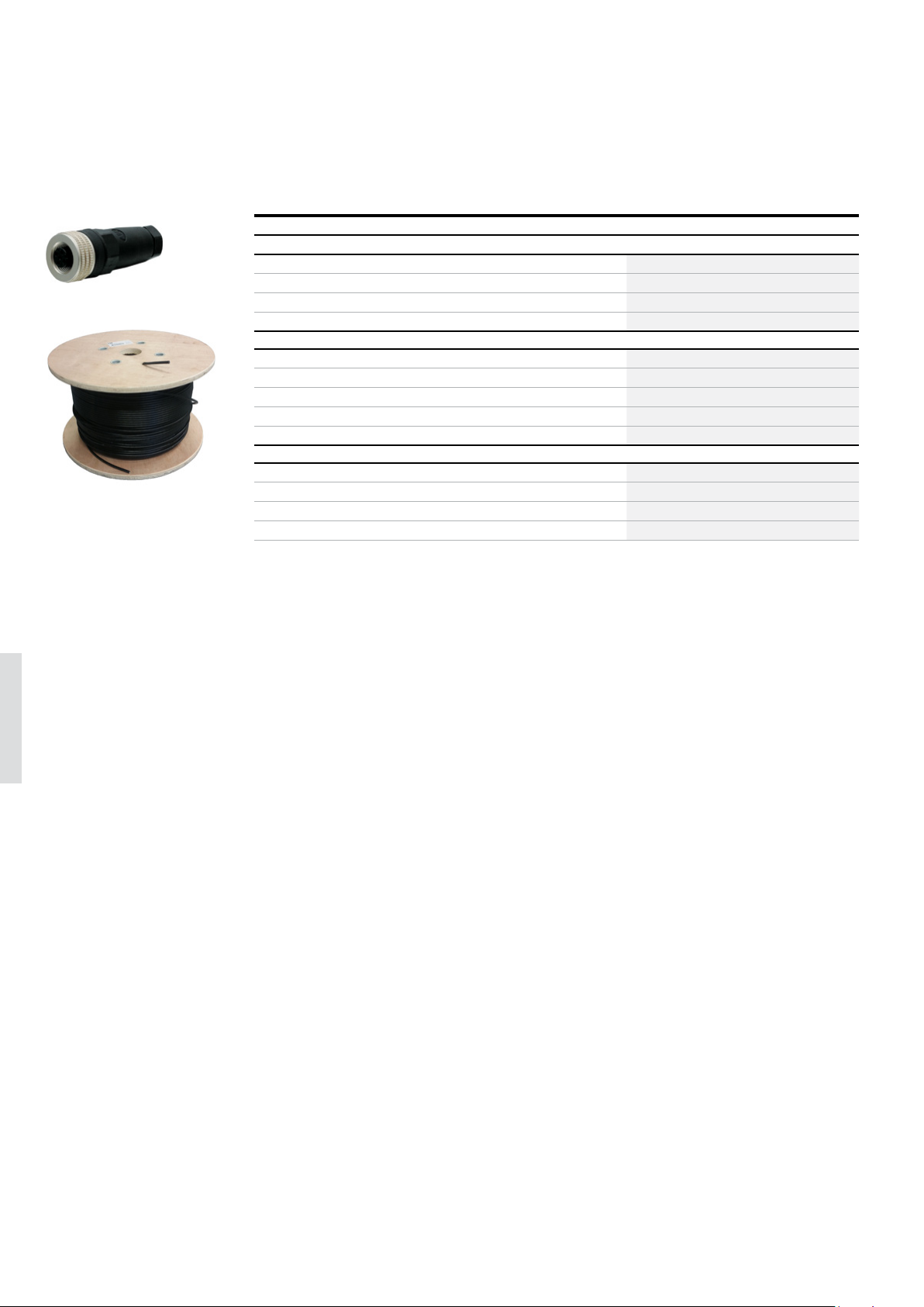
Cables
LineStrong
M12-C01
C5 cable
SAFETY PRODUCTS CATALOG ABB JOKAB SAFETY
—
LineStrong
Description Typ e Order code
Connectors
2TLC172657F0201
M12-5 pole female, straight M12-C01 2TLA020055R1000
M12-5 pole male, straight M12-C02 2TLA020055R1100
M12-8 pole female, straight M12-C03 2TLA020055R1600
M12-8 pole male, straight M12-C04 2TLA020055R1700
Cable with 5 conductors
10 m cable with 5 x 0.34 shielded conductors C5 cable 10 m 2TLA020057R0001
50 m cable with 5 x 0.34 shielded conductors C5 cable 50 m 2TLA020057R0005
100 m cable with 5 x 0.34 shielded conductors C5 cable 100 m 2TLA020057R0010
200 m cable with 5 x 0.34 shielded conductors C5 cable 200 m 2TLA020057R0020
500 m cable with 5 x 0.34 shielded conductors C5 cable 500 m 2TLA020057R0050
Cable with 8 conductors
50 m cable with 8 x 0.34 shielded conductors C8 cable 50 m 2TLA020057R1005
2TLC010038F0201
100 m cable with 8 x 0.34 shielded conductors C8 cable 100 m 2TLA020057R1010
200 m cable with 8 x 0.34 shielded conductors C8 cable 200 m 2TLA020057R1020
500 m cable with 8 x 0.34 shielded conductors C8 cable 500 m 2TLA020057R1050
6
Page 31
EMERGENCY STOPS AND PILOT DE VICES 6 – 31
—
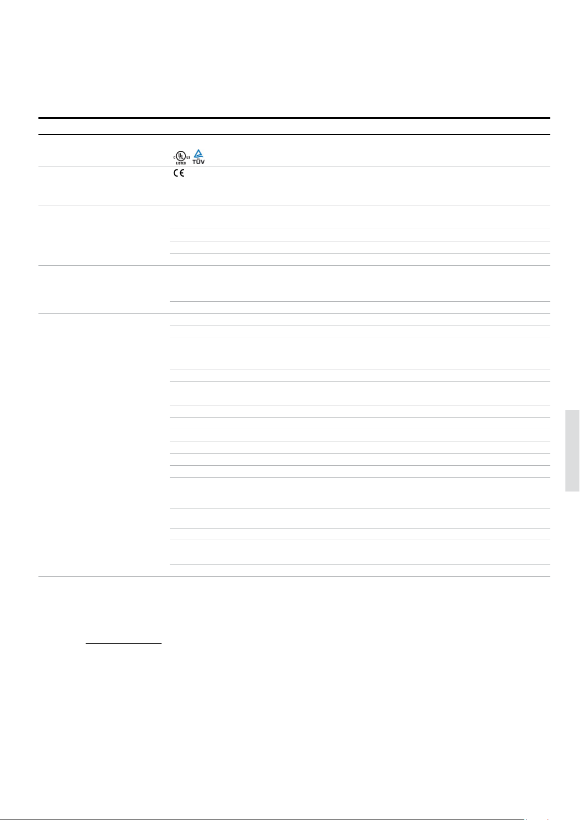
Technical data
LineStrong
Technical data
Approvals
LineStrong
Conformity
LineStrong
Functional safety data
EN ISO 13849-1:2008 Up to Cat. 4, PL e, depending on system architecture.
EN/IEC 62061:2005 Up to SILCL3, depending on system architecture.
IEC 61508 Up to SIL3, depending on system architecture.
B10
d
Electrical data
Utilization category 240 VAC / 3 A
LED +24 VDC
Mechanical data
Operating temperature -25…+80 °C
Protection class
LineStrong1, LineStrong2,
LineStrong3
LineStrong2Z, LineStrong3Z IP66, IP67, IP69K
Weight
LineStrong1 675 g
LineStrong2 880 g
LineStrong2Z 1635 g
LineStrong3L/R 1100 g
LineStrong3LZ/RZ 2000 g
LineStrong3D 1320 g
LineStrong3DZ 2200 g
Material
LineStrong1, LineStrong2,
LineStrong3D/L/R
LineStrong2Z, LineStrong3LZ/RZ/DZStainless steel 316
2006/42/EC - Machinery
EN ISO 12100:2010, EN ISO 13850:2008, EN 60204-1:2006+A1:2009, EN 60947-1:2007+A1:2011, EN 60947-5-1:2004+A1:2009,
EN 60947-5-5:1997+A1:2005
1 500 000
+24 VDC / 2.5 A
IP67
Die cast painted yellow
6
Wire type PVC sheath steel wire 4.0 mm outside diameter
Conduit entries
LineStrong1/2 3 x M20 x 1.5
LineStrong3 4 x M20 x 1.5
More information
Fore more information, e.g. the complete technical information, see product manual for:
LineStrong 2TLC172248M0201
Page 32
6– 3 2 SAFETY PRO DUCTS C ATALOG ABB JOKAB SAFETY
—
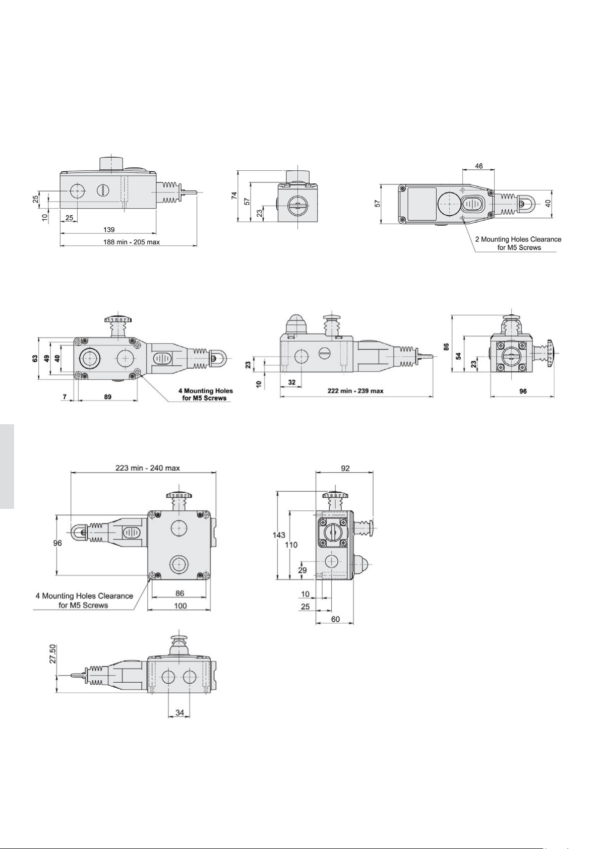
Dimension drawings
LineStrong
LineStrong1
LineStrong2
LIneStrong3L-R
6
All dimensions in mm
Page 33

EMERGENCY STOPS AND PILOT DE VICES 6– 3 3
6
Page 34
6– 3 4 SAFET Y PRODUCTS CATALOG ABB JOKAB SAFETY
—
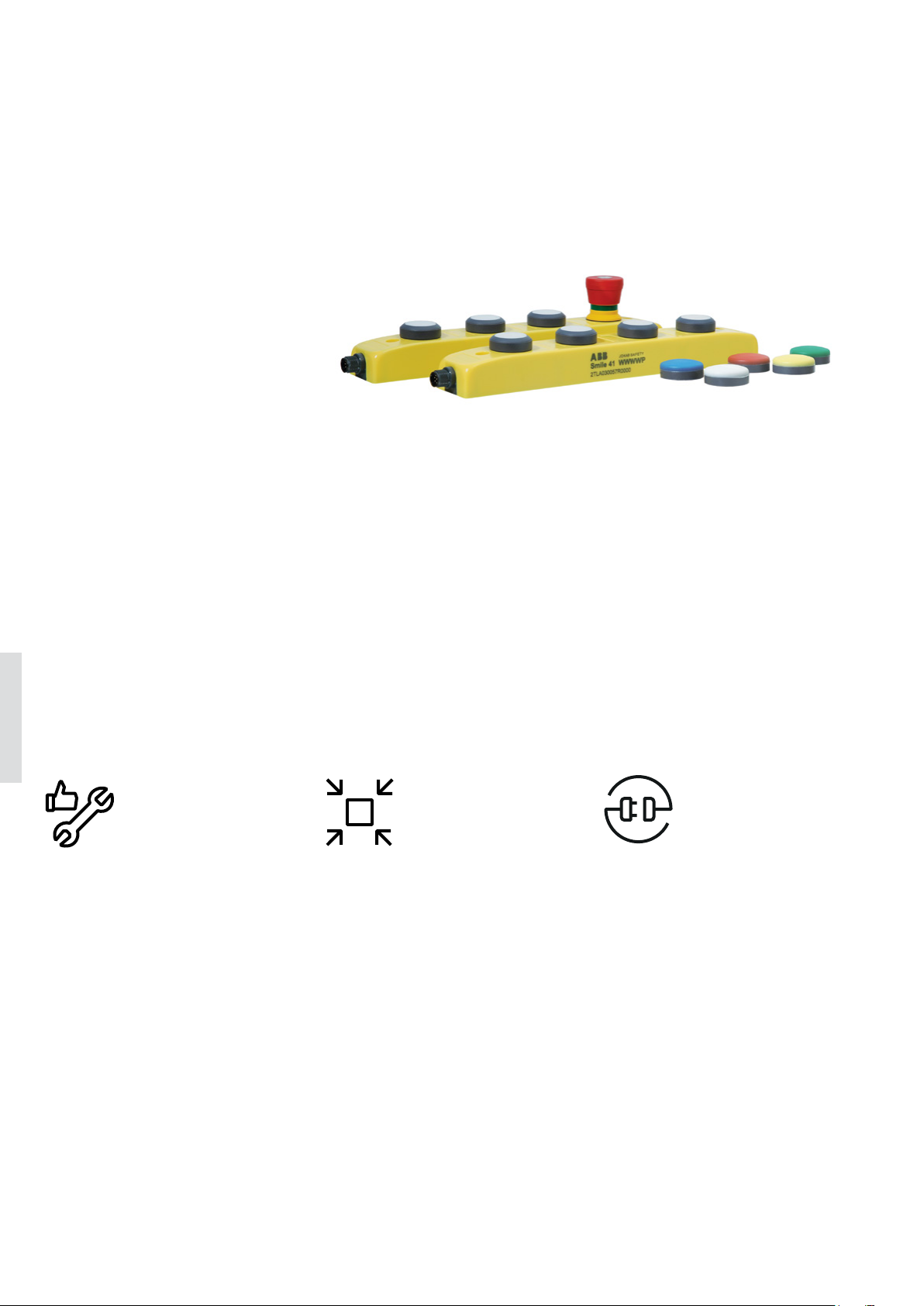
Push-button box
Smile 41
Smile 41 is a push-button box that
gathers push buttons, an emergency
stop button and a safe key selector in
a single compact device with only one
M12 connector for all functions.
Smile 41 push-button box is available
in models for use with Pluto programmable safety controller and models
for all types of AS-i safety monitors.
A kit of colored filters is supplied and
the color of each button can be chosen after delivery and changed later.
6
Easy to install
Space saving
Optimum interface
Easy to attach to profiles
The centered mounting holes makes
Smile 41 easy to attach to e.g. aluminum extrusions profiles like QuickGuard.
Quick installation
The four buttons are connected with
only one M12 connector which speeds
up the connection. A maximum of 8
wires need to be connected for the
complete push-button box with LEDs.
The AS-i models also offer the flexibility of vampire connectors with piercing
technology and self-healing cables.
Compact housing
A compact and appealing housing
saves space and makes it easy to place.
LED indication
All push-buttons and emergency stop
buttons are illuminated. The lighting of the push-buttons can easily be
managed by the Pluto programmable
safety controller, allowing a greater
adaptation to the needs.
Several button colors
The color of each button can be chosen
after delivery and changed later.
Page 35
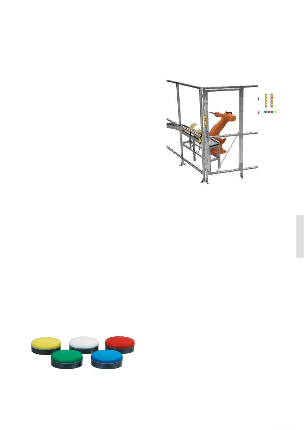
EMERGENCY STOPS AND PILOT DE VICES 6– 3 5
—
Applications and features
Smile 41
Applications
Smile 41 is a convenient way to gather several buttons at
the same place while reducing cabling and installation. For
example, an emergency stop button, a push button used to
request the unlocking of the door, a push button used as
reset button, and a push button used as start button.
Features
With Pluto programmable safety controller without AS-i
function
The Smile 41 models without AS-i function have been developed for use with Pluto programmable safety controller and
allow to get all the advantages of the Pluto “light-button
function”: only one I/O (IQ) is necessary for both a push-button and its LEDs and the lighting of the reset buttons can be
handled by Pluto without any extra programming.
The emergency stop button satisfies the highest level of
safety, and although only one cable is used for the signals of
the four buttons, a possible short-circuit can be detected by
Pluto and the highest level of safety can be reached.
Kit of colored filters
A kit of colored filters is supplied with all models and the
color of each push button can be chosen after delivery and
changed later.
With AS-i safety monitor e.g. Pluto AS-i and Pluto B42 AS-i
All AS-i models of Smile 41 can be used with any AS-i safety
monitor. The AS-i system significantly reduces the necessary
cable lengths and the M12 connector speeds up the connection. The vampire connectors with piercing technology and
self-healing cables facilitate changes.
Both the safe key selector and the emergency stop button
satisfy the highest level of safety. Moreover, the use of AS-i
Safety makes it easy to reach the highest level of safety
while eliminating most risks of connection mistakes.
The push buttons and the emergency stop button are
equipped with an easily programmed LED for a perfect
adaptation to the needs of the application, a better user
friendliness and easier troubleshooting.
Centered mounting holes
Centered mounting holes facilitate the mounting of Smile 41
on aluminum profiles like Quick-Guard.
6
Page 36
6– 3 6 SAFET Y PRODUCTS CATALOG ABB JOKAB SAFETY
—
Ordering information
Smile 41
—
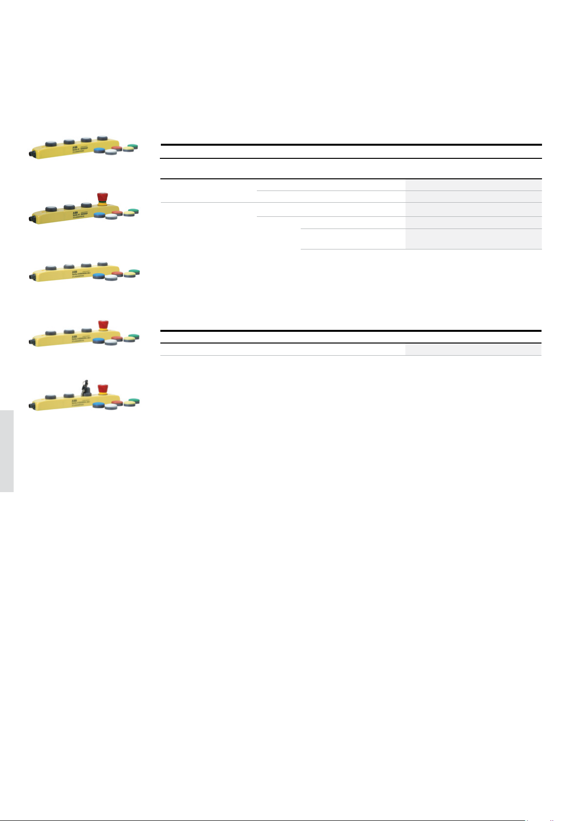
Smile 41 push button box
All Smile 41 push-button boxes are delivered with a kit of filters
2TLC172715F0201
Smile 41 WWWWP
Smile 41 EWWWP
Safety controller Emergency
Pluto programmable safety
controller
AS-i monitor*
2TLC172717F0201
* E.g. Pluto AS-i and Pluto B42 AS-i
stop button
0 4 push-buttons M12-8 male Smile 41 WWWWP 2TLA030057R0000
1 3 push-buttons M12-8 male Smile 41 EWWWP 2TLA030057R0100
0 4 push-buttons M12-5 male Smile 41 WWWWN ASi 2TLA030056R0000
1
Other buttons Connector Typ e Order code
3 push-buttons M12-5 male Smile 41 EWWWA ASi 2TLA030056R0100
1 safe key selector
2 push-buttons
M12-5 male Smile 41 EKWWA ASi 2TLA030056R0200
Smile 41 WWWWN AS-i
Smile 41 EWWWA AS-i
Smile 41 EKWWA AS-i
6
2TLC172602F02012TLC172605F02012TLC172703F0201
—
Spare parts
Description Typ e Order code
Kit of colored filters Colored filters 2TLA030059R2600
Page 37
EMERGENCY STOPS AND PILOT DE VICES 6 – 37
—
Cables and connectors
Smile 41
2TLC172951F0201
M12-C61
2TLC010003F0201
M12-C61HE
2TLC172931F0201
M12-C334
—
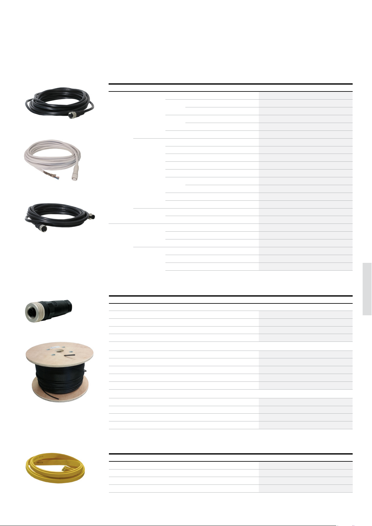
Cable with connectors
Connector Female/male Length Special feature Type Order code
M12-5 Female 3 m M12-C31 2TLA020056R0500
6 m M12-C61 2TLA020056R0000
Harsh environment, halogen free M12-C61HE 2TLA020056R8000
10 m M12-C101 2TLA020056R1000
Harsh environment, halogen free M12-C101HE 2TLA020056R8100
20 m M12-C201 2TLA020056R1400
Female + male 0.3 m M12-C0312 2TLA020056R5800
0.06 m M12-C00612 2TLA020056R6300
1 m M12-C112 2TLA020056R2000
3 m M12-C312 2TLA020056R2100
6 m M12-C612 2TLA020056R2200
10 m M12-C1012 2TLA020056R2300
Angled female connector M12-C1012V2 2TLA020056R6700
16 m M12-C1612 2TLA020056R5400
20 m M12-C2012 2TLA020056R2400
Male 6 m M12-C62 2TLA020056R0200
10 m M12-C102 2TLA020056R1200
M12-8 Female 6 m M12-C63 2TLA020056R3000
10 m M12-C103 2TLA020056R4000
20 m M12-C203 2TLA020056R4100
Female + male 0.06 m M12-C00634 2TLA020056R6400
1 m M12-C134 2TLA020056R5000
3 m M12-C334 2TLA020056R5100
M12-C01
C5 cable
AS-i cable yellow
2TLC172657F0201
—
Separate cables and connectors
Description Typ e Order code
Connectors
M12-5 pole female, straight M12-C01 2TLA020055R1000
M12-5 pole male, straight M12-C02 2TLA020055R1100
M12-8 pole female, straight M12-C03 2TLA020055R1600
M12-8 pole male, straight M12-C04 2TLA020055R1700
Cable with 5 conductors
10 m cable with 5 x 0.34 shielded conductors C5 cable 10 m 2TLA020057R0001
50 m cable with 5 x 0.34 shielded conductors C5 cable 50 m 2TLA020057R0005
100 m cable with 5 x 0.34 shielded conductors C5 cable 100 m 2TLA020057R0010
200 m cable with 5 x 0.34 shielded conductors C5 cable 200 m 2TLA020057R0020
500 m cable with 5 x 0.34 shielded conductors C5 cable 500 m 2TLA020057R0050
Cable with 8 conductors
2TLC010038F0201
50 m cable with 8 x 0.34 shielded conductors C8 cable 50 m 2TLA020057R1005
100 m cable with 8 x 0.34 shielded conductors C8 cable 100 m 2TLA020057R1010
200 m cable with 8 x 0.34 shielded conductors C8 cable 200 m 2TLA020057R1020
500 m cable with 8 x 0.34 shielded conductors C8 cable 500 m 2TLA020057R1050
—
Cables and connection accessories for AS-i
Description Typ e Order code
Cable for AS-i, power and data, +30 VDC, yellow, EPDM AS-i cable yellow 2TLA020074R9000
Cable for AS-i, additional power, +24 VDC, black, EPDM AS-i cable black 2TLA020074R9100
2TLC172742F0201
M12-5 female connector with vampire connector for AS-i flat cable. AS-i T-connector M12 2TLA020073R0000
As-i flat cable splitter used to make T-connections and to extend cables. AS-i splitter box 2TLA020073R0300
6
Page 38
6– 3 8 SAFET Y PRODUCTS CATALOG ABB JOKAB SAFETY
—
Technical data
Smile 41
Technical data
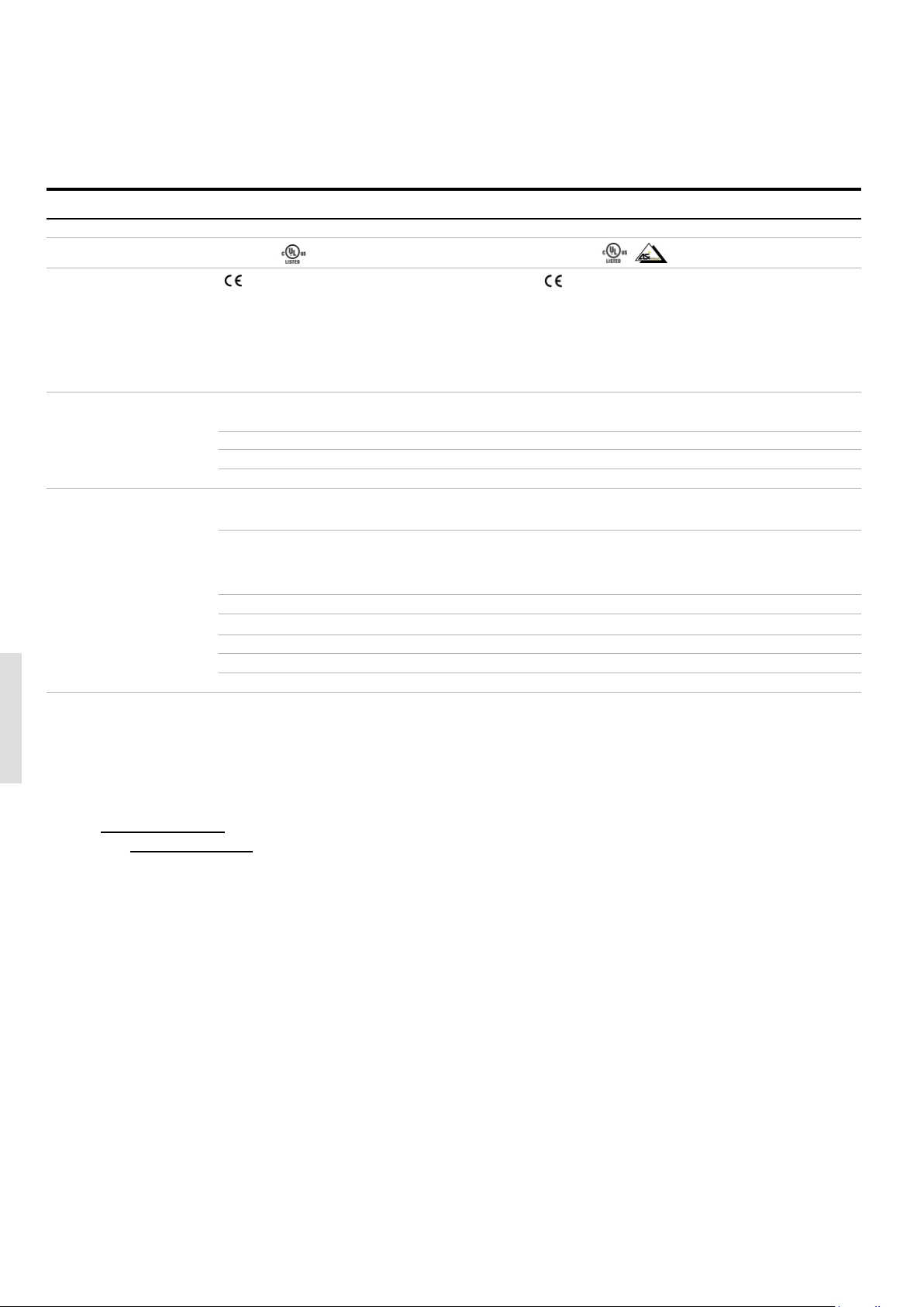
Smile 41 Smile 41 AS-i
Approvals
Conformity
Functional safety data
IEC 61508:2010 Up to SIL3, depending on system architecture SIL3, PFH
EN/IEC 62061:2005 Up to SILCL3, depending on system architecture SILCL3, PFHD = 2.87 x 10
EN ISO 13849-1:2008 Up to Cat. 4/PL e, depending on system architecture Cat. 4/PL e, PFHD = 2.87 x 10
B10
d
Electrical data
Operating voltage +24 VDC ± 15% +30 VDC (AS-i bus)
Mechanical data
Mechanical life
Emergency stop button
Illuminated push button
Key selector - 30 000
Operating temperature -25… +50 °C
Protection class IP65
Weight 190 g
TÜV NORD TÜV NORD
2006/42/EC - Machinery 2006/42/EC – Machinery
2014/30/EU - EMC 2014/30/EU – EMC
2011/65/EU - RoHS 2011/65/EU – RoHS
EN ISO 12100:2010, EN ISO 13849-1:2008/AC:2009, EN ISO 12100:2010, EN ISO 13849-1:2015, EN 62061:2005/A2:2015,
EN 62061:2005+A2:2015, EN 60204-1:2006+A1:2009, IEC 60664-1:2007, EN 60204-1:2006+A1:2009, IEC 60664-1:2007, EN 61000-6-2:2005,
EN 61000-6-2:2005, EN 61000-6-4:2011, EN ISO 13850:2015 EN 61000-6-4:2011, EN ISO 13850:2015, EN 60947-5-5:2005, EN
61508:2010
-10
65 000
> 50 000 operations
1 000 000 operations
= 2.87 x 10
D
-10
-10
6
More information
Fore more information, e.g. the complete technical information, see product manual for:
Smile 41 2TLC172280M0201
Smile 41 AS-i 2TLC172255M0201
Page 39
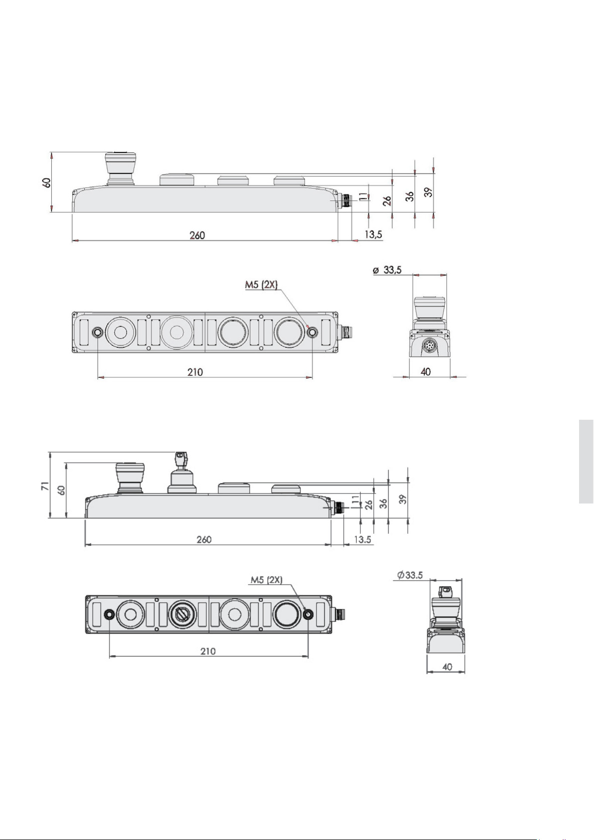
EMERGENCY STOPS AND PILOT DE VICES 6– 39
—
Dimension drawings
Smile 41
Smile 41
Smile 41 AS-i
All dimensions in mm
6
Page 40
6– 4 0 SAFETY PRODUCTS CATALOG ABB JOKAB SAFETY
—
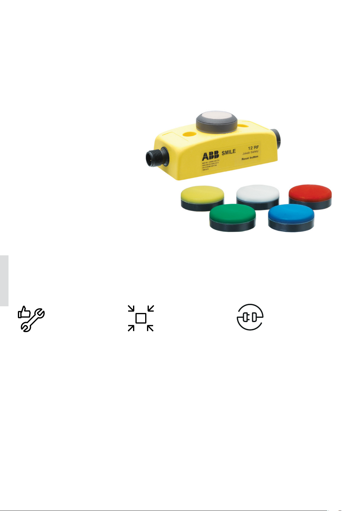
Reset button
Smile
Smile reset buttons have compact
housings with M12 connectors for
easy connection.
The reset button contains an
integrated white LED, and all buttons
are delivered with a kit of colored
filters to snap on the top of the
button. In this way the color of the
button can be chosen after delivery
and is also possible to changed later.
The different models also allow a
choice of:
- local reset connected directly to the
sensor, or
- global reset connected to the safety
control module.
6
Easy to install
Space saving
Optimum interface
Easy to attach to profiles
The centered mounting holes make
Smile easy to attach to e.g. aluminum
extrusions profiles.
Speed up installationn
The housing requires no assembly and
the M12 connectors speed up installation and reduce the risk of connection
error.
Local reset
Local reset allows to have the reset
button close to the safety device while
reducing cabling.
Compact housing
A compact and appealing housing
saves space and makes it easy to place.
Several button colors
All reset buttons are illuminated with
a white LED and the color of each button can be chosen after delivery and
changed later using colored snap-on
filters.
Page 41
EMERGENCY STOPS AND PILOT DE VICES 6– 41
—
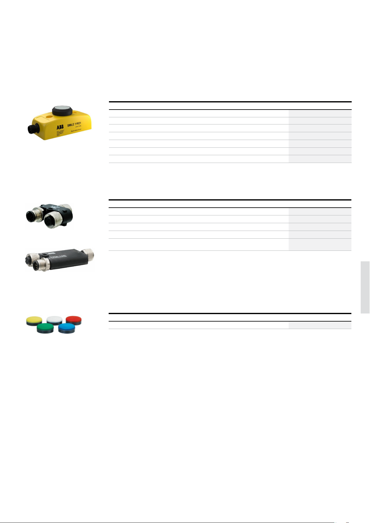
Ordering information
Smile reset buttons
2TLC172018V0201
Smile 11 RO1
2TLC172623F0201
M12-3x
—
Ordering details
Type of contact Intended use Connectors Typ e Order code
1 NO Most reset applications M12-5 male Smile 11 RA 2TLA030053R0000
1 NO Pluto Safety PLC light button function* M12-5 male Smile 11 RB 2TLA030053R0100
1 NO Local reset of Orion1 Base M12-5 male Smile 11RO1 2TLA022316R3000
1 NC Local reset of Orion2 Base and Extended, and Orion3 Extended M12-5 male Smile 11RO2 2TLA022316R3100
1 NC Local reset of Orion3 Base M12-5 male Smile 11RO3 2TLA022316R3200
1 NO
1 NO Local reset of Eden OSSD-Reset M12-8 M12-8 male + female Smile 12 RG 2TLA030053R2700
* See Pluto hardware manual for more information about the light button function
—
Accessories
Description Typ e Order code
Y-connector for series connection of DYNlink devices with M12-5 connectors, e.g. Eden. M12-3A 2TLA020055R0000
Y-connector for series connection of Adam OSSD M12-8 with M12-5 cables M12-3H 2TLA020055R0800
Y-connector for series connection of Adam OSSD M12-8 with M12-8 cables M12-3G 2TLA020055R0700
Y-connector for connection of Smile reset button to Orion. M12-3R 2TLA022316R0000
Adaptation unit of OSSD outputs to DYNlink signals for use with Vital control module or Pluto Safety PLC.
Tina 10B has an extra M12 connector for connection of a reset button.
Local reset of Eden DYN-Reset M12-5 and Eden OSSD-Reset M12-5
M12-5 male + female Smile 12 RF 2TLA030053R2600
Tina 10B v2 2TLA020054R1310
Tina 10B
Colored filters
2TLC172725F0201
2TLC172475F0201
—
Spare parts
Description Typ e Order code
Kit of colored filters (yellow, green, white, blue, red) Colored filters 2TLA030059R2600
6
Page 42
6– 4 2 SAFETY PRODUCTS CATALOG ABB JOKAB SAFETY
—
Cables
Smile reset buttons
—
Cables for Smile 12 RF (with Eden DYN/OSSD Reset M12-5)
Description Female/male Length Type Order code
M12-5 Female 6 m M12-C61 2TLA020056R0000
10 m M12-C101 2TLA020056R1000
20 m M12-C201 2TLA020056R1400
Female + male 1 m M12-C112 2TLA020056R2000
3 m M12-C312 2TLA020056R2100
6 m M12-C612 2TLA020056R2200
10 m M12-C1012 2TLA020056R2300
20 m M12-C2012 2TLA020056R2400
Male 6 m M12-C62 2TLA020056R0200
10 m M12-C102 2TLA020056R1200
Eden Reset M12-5 to
Smile 12 RF
Smile 12 RF to M12-3A
M12-3A to M12 3A
El-cabinet to M12-3A
M12-3A to el-cabinet
—
Cables for Smile 12 RG (with Eden DYN/OSSD Reset M12-8)
Connector Female/male Length Typ e Order code
M12-5 Female 6 m M12-C61 2TLA020056R0000
10 m M12-C101 2TLA020056R1000
20 m M12-C201 2TLA020056R1400
Female + male 1 m M12-C112 2TLA020056R2000
3 m M12-C312 2TLA020056R2100
6 m M12-C612 2TLA020056R2200
10 m M12-C1012 2TLA020056R2300
6
Male 6 m M12-C62 2TLA020056R0200
M12-8 Female 6 m M12-C63 2TLA020056R3000
Female + male 1 m M12-C134 2TLA020056R5000
Male By meter M12-C04 2TLA020055R1700
20 m M12-C2012 2TLA020056R2400
10 m M12-C102 2TLA020056R1200
10 m M12-C103 2TLA020056R4000
20 m M12-C203 2TLA020056R4100
3 m M12-C334 2TLA020056R5100
Eden Reset M12-8 to
Smile 12 RG
Smile 12 RG to M12-3G
or M12-3H
M12-3G to M12-3G
El-cabinet to M12-3G
M12-3G to el-cabinet
M12-3H to M12-3H
El-cabinet to M12-3H
M12-3H to el-cabinet
—
Cables for Smile 11 RX and ROx
Connector Female/male Length Type Order code
M12-5 Female 6 m
10 m
20 m
Female + male 1 m
3 m
6 m
10 m
20 m
Male 6 m
10 m
M12-C61 2TLA020056R0000
M12-C101 2TLA020056R1000
M12-C201 2TLA020056R1400
M12-C112 2TLA020056R2000
M12-C312 2TLA020056R2100
M12-C612 2TLA020056R2200
M12-C1012 2TLA020056R2300
M12-C2012 2TLA020056R2400
M12-C62 2TLA020056R0200
M12-C102 2TLA020056R1200
Smile11 Rx to another
M12
Smile 11 Rx to el-cabinet
Smile 11 ROx to Tina 10B
Tina 10B to el-cabinet
Smile 11 ROx to M12-3R
M12-3R to el-cabinet
Tina 10B to M12-3A
M12-3A to M12 3A
El-cabinet to M12-3A
M12-3A to el-cabinet
Page 43
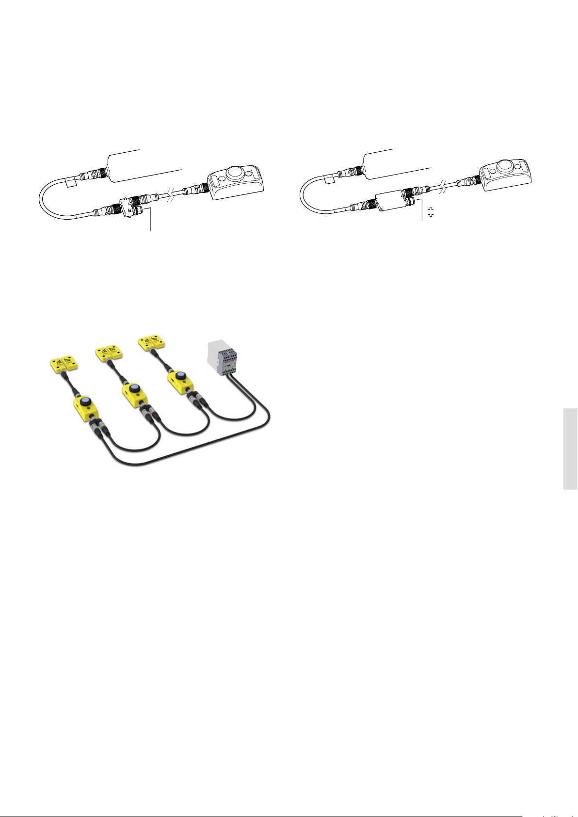
(a)
Orion receiver or active part
Tina 10B
Smile reset
1. + 24 VDC
2.
In
3.
0 V
4.
Out
5. Info
M12 5-pole male
EMERGENCY STOPS AND PILOT DE VICES 6– 43
—
Connection examples
Smile reset buttons
Local reset to Orion with Tina 10A/C Local reset to Orion with Tina 10B
Orion receiver or active part
M12-3R
(a)
M12 5-pole male
1. + 24 VDC
2. OSSD1
3.
0 V
4. OSSD2
5. -
Smile reset
Connection of Smile 11 ROx to Orion through M12-3R. For
connection to any control module compatible with OSSD
outputs.
Local reset to Eden
Serial connection of Eden with local Smile reset buttons:
- Adam OSSD-Reset M12-8 with Smile 12 RG and M12-3G or
M12-3H
- Adam DYN-Reset with Smile 12 RF and M12-3A
Connection of Smile 11 ROx to Orion through Tina 10B.
For connection to Vital control module or Pluto Safety PLC.
Global vs local reset
A global reset is connected directly to the control cabinet
with separate cables. The safety controller in the control
cabinet supervises the reset and decides the function and
actions.
A local reset is connected directly to the safety device, and
requires no communication with the control cabinet. The
safety device supervises the reset and decides the actions. A
local reset simplifies installation and minimizes cabling.
6
Page 44

6– 4 4 SAFETY PRODUCTS CATALOG ABB JOKAB SAFETY
—
Technical data
Smile reset buttons
Approvals
Power supply
LED operating voltage +24 VDC (maximum +33 VDC)
LED current consumption 20 mA at +24 VDC, 30 mA at +33 VDC
Push button operating voltage Min: +5 V, max: +35 V
Push button current Min: 1 mA, max: 100 mA
Push button rated power Max: 250 mW
Mechanical data
Color - Enclosure Yellow
Color - Push button White
Material - Housing Polyprobylene PP
Material - Contact Au
Weight Approx. 60 g
Protection class IP65
Mechanical life 1 000 000 operations at 10 mA / +24 VDC
Switching reliability 10 x
Environmental data
Ambient temperature
Humidity range
10-6 at 5 mA / +24 VDC
-25...+55 °C
35 to 85% (with no icing or condensation)
More information
Fore more information, e.g. the complete technical information, see product manual for:
Smile reset buttons 2TLC172097M0201
6
Page 45
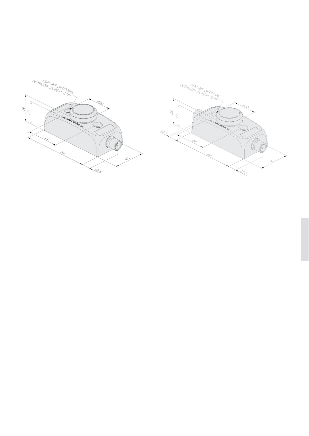
EMERGENCY STOPS AND PILOT DE VICES 6– 45
—
Dimension drawings
Smile reset buttons
Smile 11 R
All dimensions in mm
Smile 12 R
6
Page 46
6– 4 6 SAFETY PRODUCTS CATALOG ABB JOKAB SAFETY
—
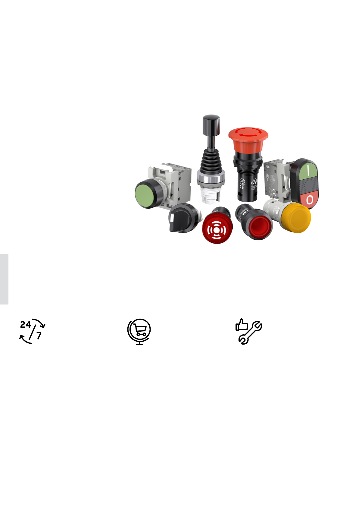
Pilot devices
Reliable products, easy to select and install
ABB pilot devices are engineered
for total reliability. Our products
are tested to extremes and proven
in the toughest environments. Their
innovative designs simplify the entire
process, from selection to installation.
Enclosures, signal towers and signal
beacons complete the portfolio.
6
Continuous operation Global availability Easy to install
Engineered for tough environments
ABB pilot devices are designed with
protection degree of up to IP69K, guaranteeing reliability in extreme environments – making ABB pilot devices ideal
for use in demanding industries such
as construction and food and beverage. An innovative design that automatically cleans contacts ensures high
reliability for all products.
Simple selection and stock management
ABB’s core offering includes the pilot
devices most in demand, so product
selection is easier, stock management
is simpler and product availability is
higher.
Support for exporters is world-class,
thanks to ABB’s standardized global
range, certified to comply with all major international standards.
Save time and space
The unique design of ABB’s modular
range enables tool-free installation
that is quick and simple. It provides
high flexibility for last-minute changes.
With its all-in-one construction, the
compact range reduces installation
space and saves time.
Page 47
—
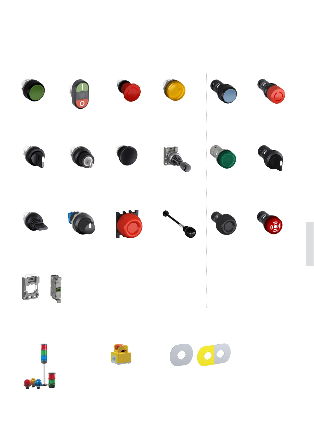
Pilot devices
Overview
EMERGENCY STOPS AND PILOT DE VICES 6 – 47
Modular range
Pushbuttons
Illuminated
and non-illuminated
Selector switches
Illuminated
and non-illuminated
Double pushbuttons
Illuminated
and non-illuminated
Key-operated
selector switches
stop pushbuttons
Illuminated
and non-illuminated
Mushroom
pushbuttons
Illuminated
and non-illuminated
Compact range
Pilot lightsEmergency
Joysticks Pilot lights
Pushbuttons
Illuminated
and non-illuminated
Emergency stop
pushbuttons
Non-illuminated
Selector switches
Non-illuminated
Potentiometers Heavy duty
Accessories for modular range
Signal towers
and signal beacons
pushbuttons
Enclosures
and stations
Legend
plates
Heavy duty
pushbuttons
BuzzersToggle switches Reset pushbuttons
6
Page 48
SAFETY PRODUCTS CATALOG ABB JOKAB SAFETY
77
 Loading...