

Page 1

SAW TRAIN
OWNER’S MANUAL
READ THIS OWNER’S MANUAL BEFORE USE AND
RETAIN IT FOR FUTURE REFERENCE.
Saw Train is a complete retrofit kit to convert your
table saw into an incredibly accurate wood
machining center. With the addition of optional
extension router tables, SmartFence® and a
fence-positioning machine, you can have one
workstation to dimension, shape, mold, joint and
dovetail - all with just one fence and one fence
machine.
The Saw Train retrofit kit consists of two cartons.
One carton contains the rails and extension table
mounting fasteners and brackets (4 brackets are
included with JST-4, 6 with JST-6 & 56, and 10 are
included with the JST-8). The second carton
contains the Sliding Bridge Assembly, SmartFence
clamping brackets, setup gauge blocks, rail-mounting fasteners,
rail end-cover plates, 48” scale and a bridge stop. THIS MANUAL
COVERS INSTALLATION AND USE OF SAW TRAIN ONLY. REFER TO THE
MANUALS INCLUDED WITH YOUR SMARTFENCE AND FENCE-
POSITIONING MACHINE FOR THEIR USE AND OPERATION.
™
TABLE SAW RETROFIT KIT
JST-8
JST-6
The Sliding Bridge Assembly and Fence brackets
are completely assembled. The fasteners required
to attach the fence brackets to the fence are
already loosely inserted in each. It is only
necessary to further loosen, engage fence T-slots
and tighten in place. The 48” scale and bridge stop
will allow you to reposition sliding bridge to make
accurate rip cuts greater than the range of your
fence machine. See Step 8.
Required tools are a Phillips screwdriver,
electric drill, 5/32” drill bit, 5/16” drill bit,
1/2” wrench and a 3/8” nut driver or wrench. JST-4
JOINTECH LIMITED WARRANTY
JOINTECH warrants this product from date of purchase against any defects that are due to faulty
material or workmanship. Please return the failed part only, transportation prepaid (proof of purchase
may be required) for free replacement or repair at our option. This warranty does not apply to
accessories. This warranty gives you specific legal rights that vary from state to state.
Should you have any questions, contact Jointech, Incorporated.
Page 2
SAFETY - READ ALL INSTRUCTIONS
The following are important safety instructions for using the JOINTECH Saw Train.
Before using Saw Train, read and follow all of the instructions and safety information in this manual.
• When using the Saw Train in conjunction with
any other tool, first read and follow all
instructions and safety information in that
tool’s owner’s manual.
• Never let any part of the Saw Train interfere
with another tool’s safety guards or other
safety equipment.
• Before using your Saw Train, make sure all
mounting screws are tight and that the bridgeclamping knob is securely tightened against
rail.
• Always turn off the power to saw or router
prior to any adjustment of Saw Train. Allow a
cutting tool to come to a complete stop before
repositioning of fence.
• Always keep both hands behind fence when
moving fence to a new setting.
• Before making a cut always make sure that
the bridge clamp is securely tightened against
rail and fence machine is securely locked in
position.
• Use appropriate safety devices. Keep hands
clear of saw blade or router bit! Always use a
push stick, rubber-soled push block, or other
safety devices to keep your hands safely
away from cutter.
• Never let the saw blade or router cutter come
into contact with any part of Saw Train or
fence machine.
• Wear safety glasses, hearing protection, and
follow all normal shop safety practices.
• Never operate your table saw without a blade
guard.
FASTENERS
EXTENSION TABLE MOUNTING HARDWARE PACK RAIL MOUNTING HARDWARE PACK
(Packed with rails) (Packed with Bridge assembly)
Description
Angle bracket
¼-20 x ½” machine screw
¼-20 heavy hex nut
¼” flat washer
#14 x 1” lag screw
JST-4
4 ea.
4 ea.
4 ea.
4 ea.
4 ea.
JST-6 & 56
6 ea.
6 ea.
6 ea.
6 ea.
6 ea.
JST-8
10 ea.
10 ea.
10 ea.
10 ea.
10 ea.
-2-
Description
5/16-18 x 1” carriage bolt
5/16-18 keps nut
Rectangular stamped washer
Bridge stop (assembled)
Rail end cover plate
#8 x ½” hex head screw
UHMW tape, 1-1/2” x 2”
6 ea.
6 ea.
6 ea.
1 ea.
4 ea.
8 ea.
1 ea
Page 3
1. RAIL INSTALLATION
Unplug your table saw, lower saw blade and remove the existing fence,
including the front and rear support rails, mounting brackets and the
blade guard.
NOTE: The blade guard must be reinstalled after you have finished
mounting the Saw Train rails to your table saw.
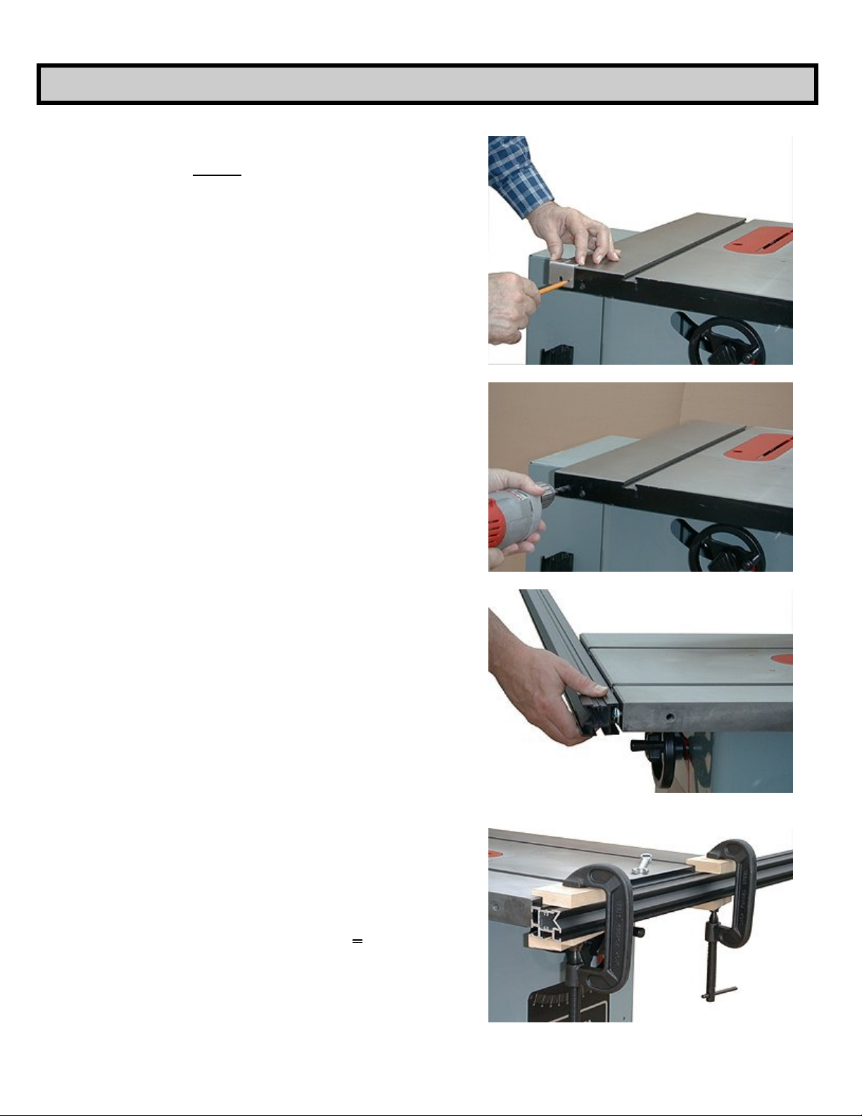
A. Drill Rail Mounting Holes.
Remove one of the angle brackets from the extension table
hardware pack. The small hole in the top surface of bracket
will be used to accurately locate position of bolt holes for
each rail. After cleaning off front and rear apron surfaces,
place bracket to overhang saw edge and mark as shown in
Figure 1. Locate near each outside edge, front and back, of
saw table. Leave enough space for access of a ½” wrench
behind apron to tighten nut. NOTE: If there is no access
behind apron to attach and tighten nuts, you must
attach rails to extension wings of saw.
Center punch and drill the four holes first using a 5/32” bit as
a pilot then follow with a 5/16” drill bit (Figure 2). Place a
rectangular flat washer on each carriage bolt, insert through
holes and loosely attach the keps nuts.
Fig. 1
B. Install Rails.
NOTE: For a custom fit of rail length to extension
tables, they may be cut off with a hacksaw, band saw or
on your table saw with a carbide-tipped saw blade.
Carefully engage carriage bolt head and washer in the large
T-slot on upper rear surface of rail. Slide forward to engage
second bolt and continue sliding to the desired position
(Figure 3). The final position will be determined by the size
of your extension table(s) and whether they will be on one or
both sides of saw.
C. Set Final Rail Position
Find the two setup gauge blocks packed with Bridge
Assembly. The gauge blocks will parallel and locate the final
rail position relative to top surface of saw. Place them on top
of rail overlapping edge of saw table as shown in Figure 4
and clamp in place. The top surface of rails should be flush
to or slightly below the bottom of the miter gauge slots.
While holding rail down so that the rabbeted end of gauge
blocks contact top surface of saw edge, securely tighten the
keps nuts with a ½” wrench. Repeat for the rear rail.
NOTE: The gauge blocks are machined to provide
correct rail position for most table saws. If your miter
gauge is deeper than the top surface of rails, it will be
necessary to lower both rails further by adding .020 .030” shims under gauge blocks.
Fig. 2
Fig. 3
-3-
Fig. 4
Page 4
2. BLADE GUARD ADJUSTMENTS
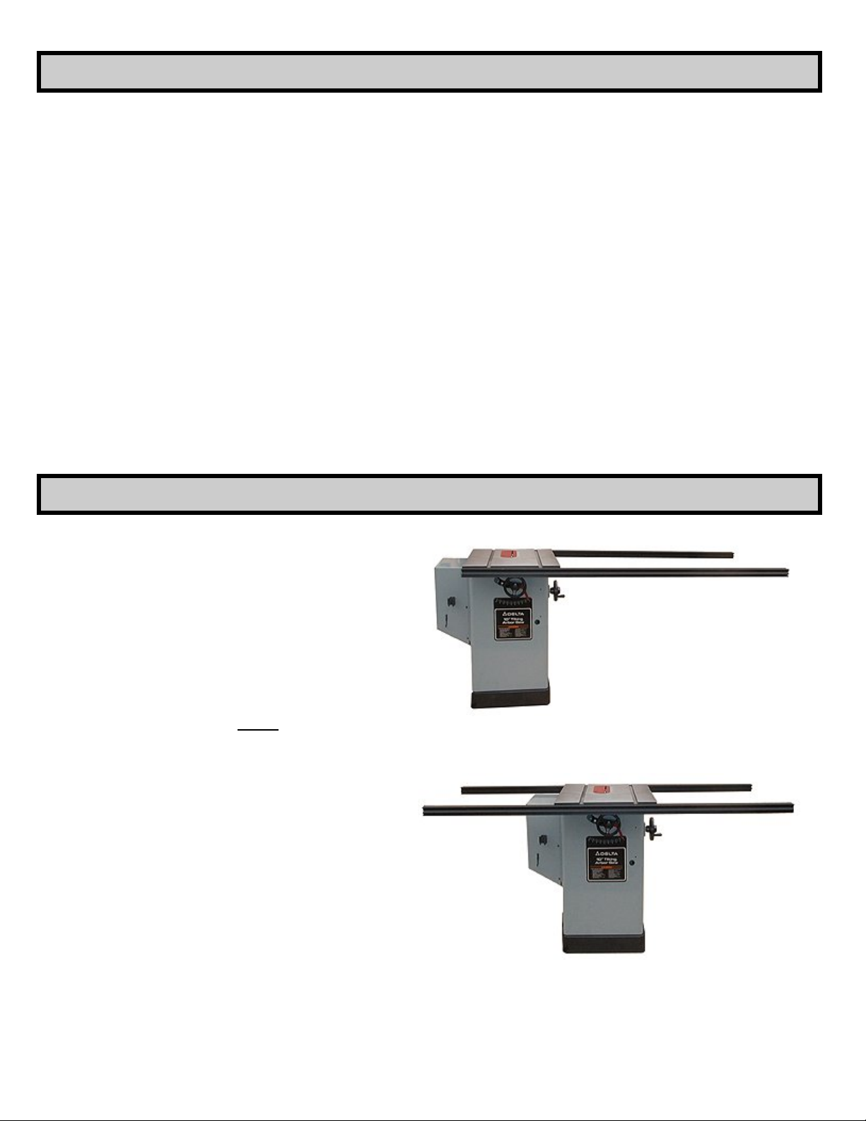
NOTE: If after reinstalling the blade guard
and tilting the motor you find that the rear rail
interferes with the blade guard, you must
either split the rear rail to provide the
necessary clearance or move the blade guard
back from interfering. If you split the rail, use
the two remaining rail mounting bolts
provided in kit.
A. Begin by removing the rear rail. Reinstall the
blade guard, and then locate the positions for the
two additional rail-mounting fasteners. They
should be placed as close as possible to the
blade guard, but before drilling the mounting
holes, make sure to check the positions for
clearance when the blade is tilted to 45º. Use
one of the angle brackets as was previously done
in Step 1-A to locate the holes.
3. EXTENSION TABLES
B. Remove blade guard and attach the extra rail-
mounting fasteners loosely in place. Use a
hacksaw to make a cut through the rear rail to
create the opening for the blade guard between
the added mounting brackets. Sand or file the cut
edges of the rails to remove any sharp edges.
C. Install the two rail sections and position them
to create an opening large enough to reinstall
blade guard. After reinstalling blade guard, again
tilt the blade to 45º to check for clearance. Refer
to Step 1-C, (Set Final Rail Position) above for
accurate repositioning of rail sections.
Extension Table mounting brackets and
fasteners can be found packed with the
rails. Tables longer than 30” in length
should be supported with 3 brackets on
each side. The lag screws supplied are
intended for 1-1/8” or thicker extension
tables. Use shorter screws for thinner tops
NOTES:
1. Extension tables must be placed
between rails over their full length
to support the Saw Train Sliding
Bridge.
2. Extension Table width should not
be wider than your saw.
Fig. 5
Fig. 6
-4-
Page 5
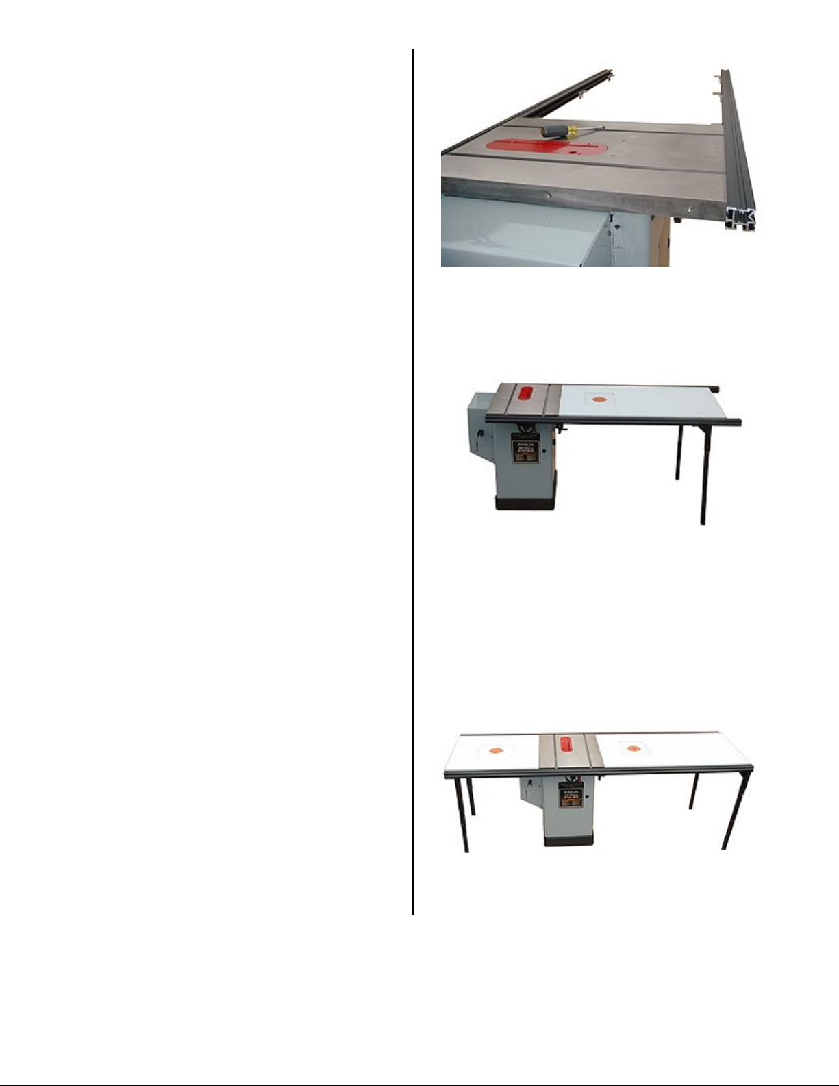
A. Installing Table
Attach a flat washer and ¼-20 hex nut to each ½”
long screw. Insert nut into lower inside T-slot on
inside face of rail and slide to positions necessary
to support your table (Figure 7). Install a bracket
onto each fastener assembly and snug in place.
(Be sure that the flat washer is under screw head
and not between rail and bracket.) Place your
extension table onto top of brackets and slide
toward saw to close gap.
NOTE: At this point you may need to attach
legs or framing to rails for support of the
added weight imbalance to your saw.
Mark the bottom of table at each bracket through
the small 1/8” hole. Remove table and drill 5/32”
pilot holes for the lag screws. Be careful not to
drill through table. This process will ensure that
each hole will be in the center of the elongated
hole that will allow rail adjustments later if
necessary. Replace tabletop, adjust brackets to
align holes and install lag screws. Snug in place
with a 3/8” nut driver, socket wrench or end
wrench. Do not tighten at this time.
B. Aligning Table
Loosen the angle bracket machine screws
attached to rail and raise table to bring flush to
saw’s top surface. Use the two setup gauge
blocks (plus shims if you used them earlier) on
front and back edges of extension table(s) to
establish parallelism and correct level of table
surfaces relative to rails over entire length of
setup. Securely tighten machine screws in place.
Fig. 7
Fig. 8
NOTE: The extension table can be mounted with the
router insert at either end. With the plate at right end,
routing operations are performed from the rear of
table saw (required with JST-4) with the Fence and
Bridge Assembly reversed. See Figure 20 on page 8.
If you wish to use table boards ¾” or thinner, the
use of wooden supports over the full length on
both sides is recommended. Obtain longer ¼”
bolts to use with the hex nuts supplied in kit to
accommodate the support board thickness. In
addition to the support boards along rails, cross
support stiffeners should also be used to
maintain a flat surface and flush fit to saw’s edge.
Screw table board to the supports.
Fig. 9
-5-
Page 6
4. SLIDING BRIDGE INSTALLATION
NOTES: The Bridge length is designed to fit
standard 27” to 28” table saws. The assembly is
factory set for a 27” saw and will need to be
adjusted to fit your particular saw. If your saw is
less than 27” you must disassemble bridge and
with a hacksaw, band saw or carbide-tipped saw
blade, cut bridge platform to the same length as
your saw.
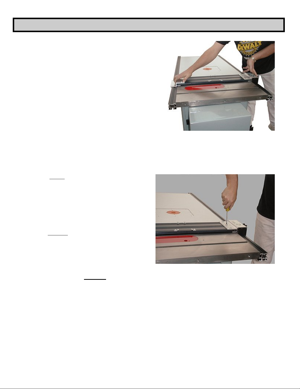
Place Bridge Assembly across your saw to engage
rear rail. Loosen the 6 top screws and pull assembly
apart as necessary to properly engage front rail while
maintaining an equal gap at each end of bridge
platform. Slide Bridge Assembly over to a miter
gauge slot on your saw for parallelism alignment
(Figure 10). Align edge of bridge to miter slot and
securely tighten the 3 screws on rear clamp. Hold the
rear bracket firm to rail and push in front bracket to
evenly snug. Securely tighten the 3 screws on front
clamp (Figure 11).
Fig. 10
Pushing at its center, slide Bridge Assembly down the
rails over your extension table. If a binding or
loosening occurs, it is necessary to adjust rails to
achieve a good sliding action over their entire length.
If a binding occurs, your table is too wide and must be
made narrower. However, an alternative to removing
and trimming your table is to place shims between the
back rail and saw table.
If too loose you must pry rails apart. After final rail
adjustments, securely tighten lag screws. If there is a
significant gap between rail and table, you should
place a shim to prevent any slippage when clamping
bridge.
NOTES:
1. Attempting to slide Bridge by pushing it
anywhere but at its CENTER will only
cause it to cock and bind against rails.
2. Leaving too much play, or gap, may affect
parallelism of fence to saw blade during
clamping of Bridge. Continue to adjust
Rails and Bridge until you achieve a close,
slip-fit all along rails. When you later
mount fence machine and fence with its
rail clamping brackets, the Bridge and
fence will be always be controlled and
maintained parallel to saw blade because
of the four points of contact to rails.
Fig. 11
-6-
Page 7
5. FENCE MACHINE INSTALLATION
NOTE: The fastening method used will
accommodate nearly any fence machine positioner
or jig. To allow full positioning range of machine,
you will want the front end of machine to overhang
bridge platform 2 to 3 inches to provide space for
the SmartFence clamping knobs and the front,
fence-clamping bracket
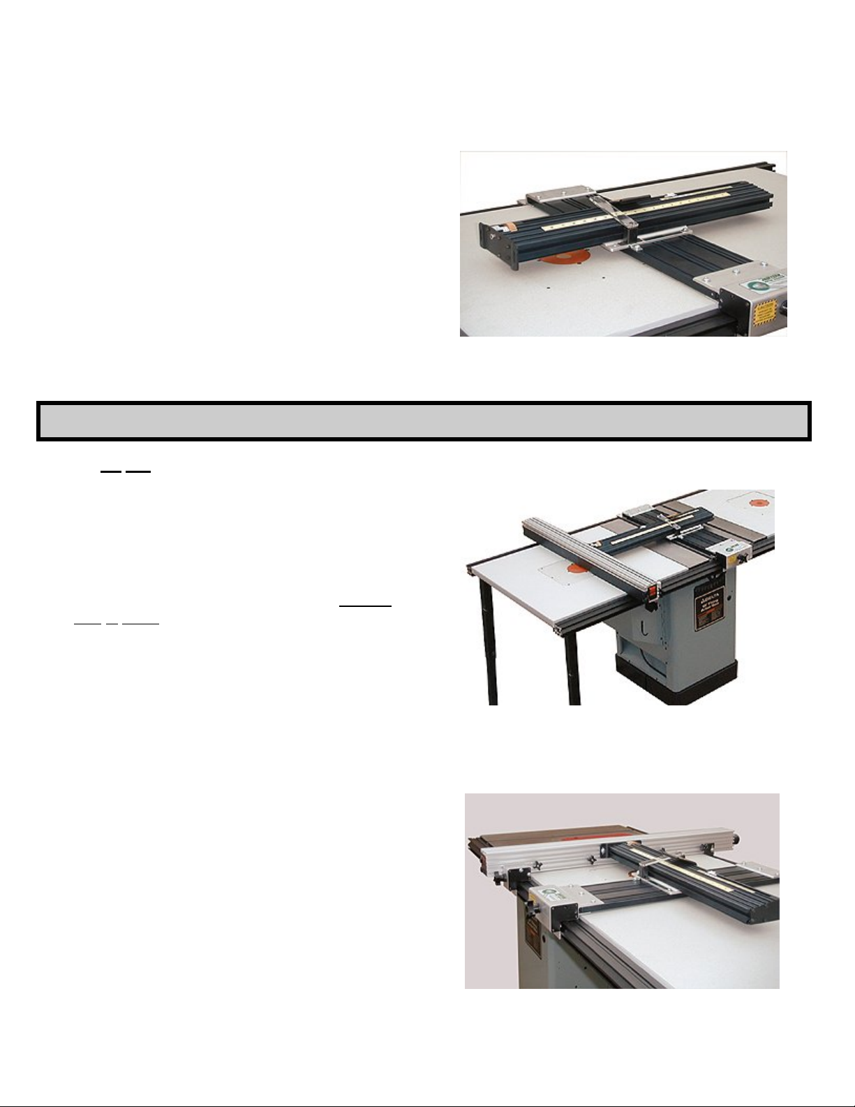
Tighten down Sliding Bridge Assembly with its front
clamping knob. Loosen the screws on bridge platform
with the pinch brackets and slide back out of the way.
Remove the 2 longer screws at the backside of platform
and insert them through both holes (or slots) at right
edge of base of your fence positioner and engage nuts
in the T-slot. Slide the pinch brackets up to overlap the
front and rear edges of machine base. Center machine
on bridge platform and leave screws somewhat loose for
centering and skew adjustments later (Figure 12).
6. FENCE INSTALLATION
NOTE: Do Not use glide tape underneath fence.
With proper installation of the rails and fence you
should achieve a gap of .010 - .020” under fence.
The only points of contact in your final setup should
be the bottom surfaces of bridge and fence clamp on
the rails.
Fig. 12
A. Attach Fence to Machine
Open carriage of your fence machine to its halfway point
and lock in place with its clamping lever or knob.
Move Sliding Bridge Assembly over onto extension table
and to the right of your router plate insert to a position
where that when your fence is placed across table and
fastened to fence machine its face can be aligned to
center of router plate (Figure 13). Center your fence’s
center to the exact center of your router plate. Slide
Bridge Assembly up to make contact of fence machine’s
fence-mounting bracket to back surface of fence.
Adjust your fence machine on bridge platform to be
centered between knobs on back of SmartFence.
Loosely fasten fence to machine with the screws
provided with fence (refer to its manual if necessary).
Place thin shims, approximately .020” (thickness of 2
business cards), under each end of fence. Now,
securely tighten the two, fence-mounting screws.
Move the bridge over to bring the face of fence to a miter
gauge slot on the saw and lock in place (Figure 14).
Adjust the base of machine on bridge to align fence
parallel to slot. Securely tighten the four, machinemounting screws on bridge. This procedure will ensure
that the fence machine is parallel to rails.
-7-
Fig. 13
Fig. 14
Page 8
NOTE: Make sure that Bridge is locked and the
fence machine is in the center of its range and
locked to prevent any lateral movement of carriage.
B. Attach Fence Brackets
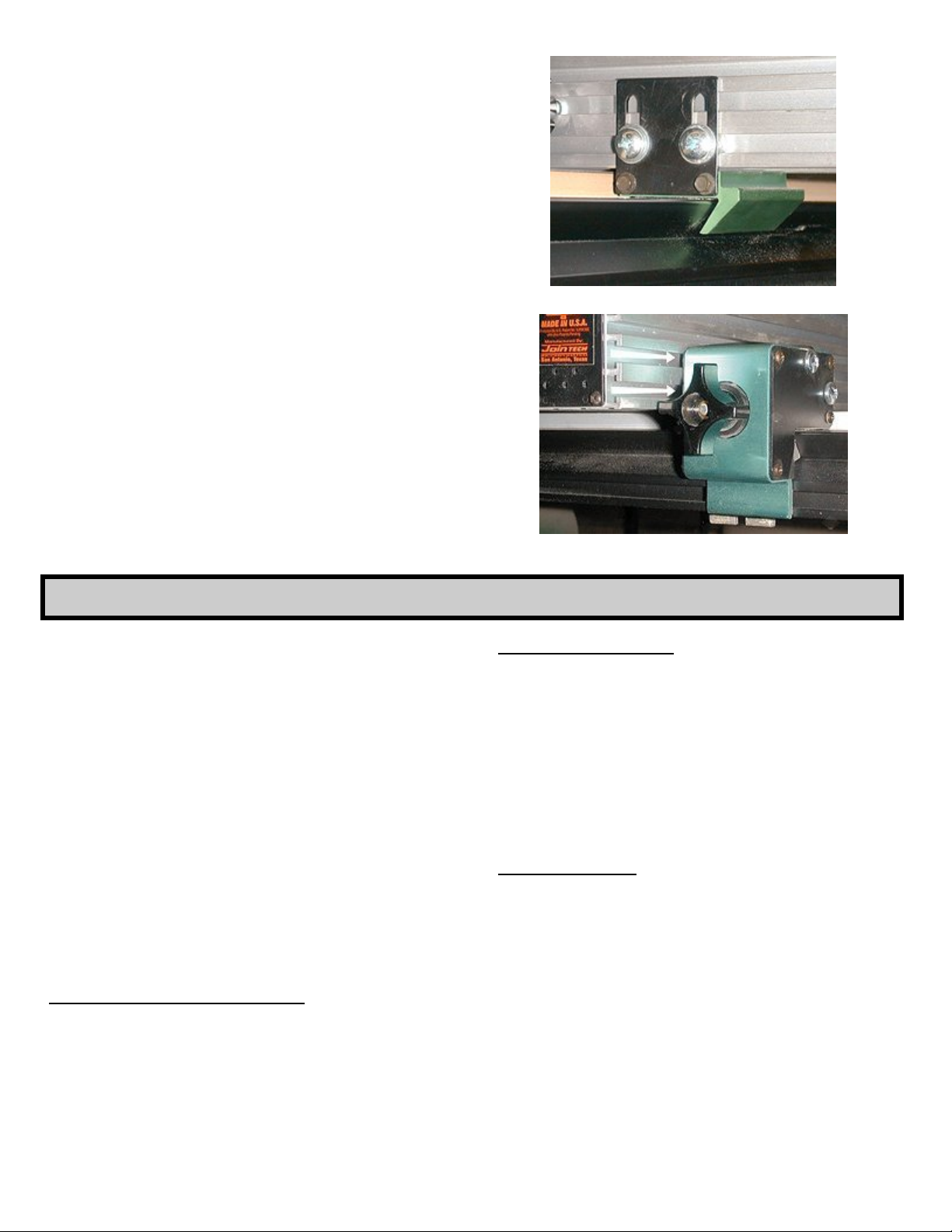
Place the shims under each end of fence again. Install
the Back Fence Clamp bracket under out feed end of
fence engaging the ¼” nuts into one or both fence Tslots. Push against rail and securely tighten screws
(Figure 15).
Install the Front Fence Clamp bracket by engaging its
two ¼” nuts into the two lower fence T-slots. Push in,
align clamp bottom surface to rail top surface and
securely tighten screws (Figure 16).
NOTE: To achieve a gap under infeed end of fence,
you may need to add another layer of UHMW tape to
the bottom surface of the front fence clamp. (An
extra strip of UHMW tape is packed with the Rail
Mounting Hardware.)
Remove shims from underneath fence. Check slip fit of
fence brackets along rails by moving fence. Do not
force so tight against rails as to cause binding nor leave
too loose as this may affect fence parallelism when
clamping bridge.
Fig. 15
Fig. 16
7. FINAL ALIGNMENT
The normal criteria for table saw fence alignment is to
skew the fence away from the trailing edge of saw blade
to prevent binding, burning and/or secondary scoring
during cutting operations. This skew should be .003” to
.005” greater than the maximum wobble of your saw
blade.
Note: If you use your dust collector during table saw
operations, you can align your fence perfectly parallel to
blade. The vacuum porting on the lower face of your
SmartFence will hold the work piece against fence and
prevent any secondary scoring (Ideal for cutting
veneer!).
Raise your saw blade. With your fence machine still in
the center of its range and locked, release the bridge
clamp and slide complete setup to touch fence to saw
blade. Clamp bridge in place.
To Set Fence Parallel To Blade:
Check contact of blade to fence. If necessary to correct
alignment (your blade may be out of parallel to the miter
gauge slot), loosen the two fence mounting screws on
back of fence and place the necessary shims (either
magic tape or masking tape work well) on one side of
bracket between fence and machine. Securely tighten
fence-mounting screws after any adjustment.
-8-
To Set a Fence Skew:
Take a dollar bill folded in half to use as a shim
between fence and trailing edge of blade. Loosen
the 2 fence mounting screws on back of fence and
place the necessary shims between one side of
bracket and back of fence until fence touches
blade at its leading edge and pinches the dollar bill
at its trailing edge. Securely tighten fencemounting screws.
Lower saw blade.
Final Adjustment
Release cam lever on fence machine and slide
positioner fully open to closed. If any binding
occurs, first check fence clamps for binding. If
binding persists, slightly loosen gib screws on
Clincher (see Clincher Handbook) until you get
smooth travel over its full range.
With the fence machine set to the center of its
range and locked in place, release bridge clamp
and slide complete unit down the rails. If any
binding occurs recheck previous setup procedures
for rails, table elevation and fit of fence and bridge
clamps to rails.
Page 9
8. OPERATION: REPOSITIONING & REVERSING BRIDGE
A. Repositioning Bridge
Normal setup of your fence for ripping is to fully open
the fence machine, lock, and then slide complete
assembly over until face of fence just touches saw
blade. Firmly clamp Bridge in place. The scale on
the machine is then adjusted to align its zero to the
cursor. Exceptionally accurate rip cuts - up to the
total range of your machine - can then be performed
by using the machine scale.
To increase the ripping capacity beyond the range of
your machine, the entire Fence/Bridge Assembly can
be repositioned further down the rails. Your rail
length then is what limits your total rip capacity unless
you attach a Jointech Extension Table to right end of
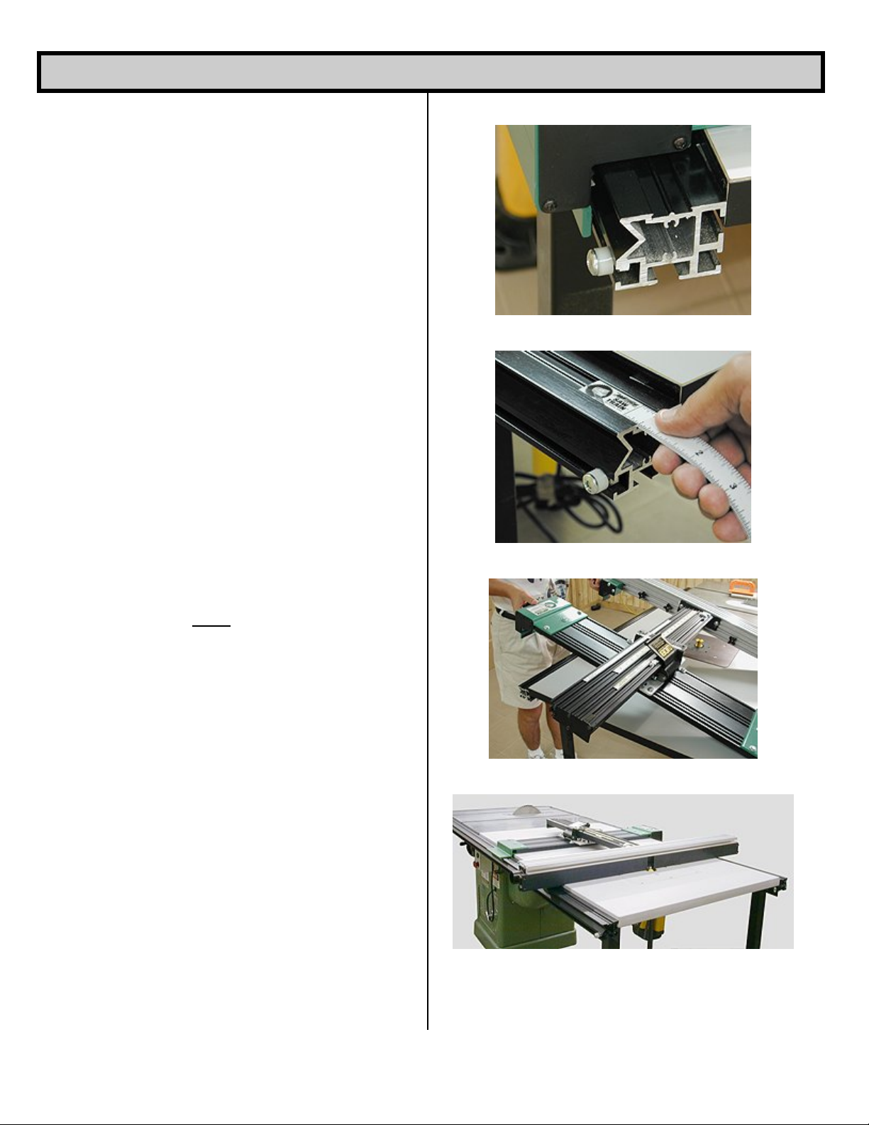
saw. You can achieve “tape measure” accuracy by
installing the 48” scale into top of front rail (see figure
18). To calibrate this scale, reference its ‘zero’ mark
to right edge of fence clamping bracket with the fence
zeroed to blade. Another method to achieve very
accurate rip cuts is as follows;
1. Zero fence to blade with machine scale set to
its zero.
2. Clamp Bridge in place and move fence back to
nearly its maximum range to an even inch
mark. For example; 18.00” for the CL-18
Clincher.
3. Firmly Clamp fence in place.
4. Unlock Bridge clamp and with fence still
locked in place, slide Bridge to right until the
machine scale reading is zero again and lock
in place.
5. Loosen Fence clamp.
You have now created an offset exactly equal to the
range of your machine. When making a cut now, just
add this offset to the machine scale reading.
Fig. 17
Fig. 18
Fig. 19
Install the Bridge Stop in the lower T-slot on front rail
as shown in figure 17. The stop can be used for the
‘offset’ described above or for a maximum setting.
B. Reversing Sliding Bridge Assembly
To remove the Fence/Bridge Assembly, simply
release both clamping knobs several turns and lift up
from front of table as shown in figure 19. Unhook
from rear rail and remove. Unless you have space
limitations, the Assembly can be reinstalled from rear
of saw table and used in the same manner as from
the front except that you will be working from the rear
of table saw.
Fig. 20
-9-
Page 10
MAINTENANCE
Your Saw Train is designed to give many years of virtually maintenance-free
operation. An occasional cleaning is all you need to do to keep the tool in top
shape. Remove the Sliding Bridge and fence from saw, invert and clean the
rubber clamping pads of any dust buildup or grime. A light application of
paste wax to the top surface of the rails from time to time will keep the rails
smooth and clean.
OPTIONAL SAW TRAIN ACCESSORIES
EXTENSION TABLES WITH ROUTER PLATE CUTOUT
27 x 28 x ¾ Solid Phenolic STT-2728P
27 x 36 x ¾ Solid Phenolic STT-2736P
27 x 48 x ¾ Solid Phenolic STT-2748P
27 x 28 x 1-1/8 Melamine MDF STT-2728M
27 x 36 x 1-1/8 Melamine MDF STT-2736M
27 x 48 x 1-1/8 Melamine MDF STT-2748M
28 x 48 x 1-1/8 Melamine MDF STT-2848M
(Solid phenolic tables include special brackets that allow
expansion to fit saws from 27” to 28”)
EXTENSION TABLES WITH NO CUTOUT (BLANK)
27 x 28 x ¾ Solid Phenolic STT-2728PB
27 x 36 x ¾ Solid Phenolic STT-2736PB
27 x 48 x ¾ Solid Phenolic STT-2748PB
27 x 28 x 1-1/8 Melamine MDF STT-2728MB
27 x 36 x 1-1/8 Melamine MDF STT-2736MB
27 x 48 x 1-1/8 Melamine MDF STT-2748MB
28 x 48 x 1-1/8 Melamine MDF STT-2848MB
(Solid phenolic tables include special brackets that allow
expansion to fit saws from 27” to 28”)
ROUTER PLATE INSERTS, 3/8” LAMINATED PHENOLIC
Blank insert RP-00
Insert with 2” hole RP-20
Insert with 3-5/8” hole RP-36
3-ring universal plate RP-60
Universal, all aluminum plate RP-99
4-pc ring set for RP-99 & RP-60 RL-4RS
27” X 28” FLOATING EXTENSION ROUTER TABLE
Complete with: SFT-2728M
STT-2728M Router Extension Table
Pair of 28” Saw Train Rails
Mounting hardware, “living” rail connector and
alignment/guide pins with clamps.
Pair of Telescoping Legs (STL-1)
Also available without router cutout: SFT-2728MB
Solid Phenolic with cutout SFT-2728P
Solid Phenolic without cutout SFT-2728PB
27” X 17-1/2” FLOATING ROUTER TABLE
Complete with: SFT-2717M
17-1/2” x 27” Extension Table
Pair of 17-1/2” Saw Train Rails
Mounting hardware, “living” rail connector and
alignment/guide pins with clamps
Pair of Telescoping Legs (STL-1)
Also available without router cutout: SFT-2717MB
Solid Phenolic with cutout SFT-2717P
Solid Phenolic without cutout SFT-2717PB
PAIR, FLOATING TABLE EXTENDER BARS
12” length w/clamping knobs SEB-12
32” length w/clamping knobs SEB-32
RAIL ALIGNMENT & GUIDE PIN SET SGA-1
CLINCHER FENCE MACHINES
12 ½“ positioning range CL-12
18 ½” positioning range CL-18
26 ½” positioning range CL-26
SMARTFENCE
®
32” length SF-32
38” length SF-38
CABINETMAKER’S SYSTEMS
CL-12 & SF-32 JCM-1232
CL-12 & SF-38 JCM-1238
CL-18 & SF-32 JCM-1832
CL-18 & SF-38 JCM-1838
CL-26 & SF-32 JCM-2632
CL-26 & SF-38 JCM-2638
TABLE FEATHER BOARD
Dual level w/2 feathers ST-FB
TELESCOPING LEGS, PAIR STL-1
-10-
Page 11

Page 12

Jointech Building Trades and Home Shop
Five Year Limited Warranty
JOINTECH will repair or replace, at its expense and at its option, any part which in normal use has
proven to be defective in workmanship or material, provided that the customer returns the product
prepaid to the Jointech factory with proof of purchase of the product within five years and provides
Jointech reasonable opportunity to verify the alleged defect by inspection. Jointech will not be
responsible for any asserted defect that has resulted from normal wear, misuse, abuse or repair or
alteration made or specifically authorized by anyone other than Jointech or authorized
representative. Under no circumstances will Jointech be liable for incidental or consequential
damages resulting from defective products. This warranty is Jointech’s sole warranty and sets
forth the customer’s exclusive remedy, with respect to defective products; all other warranties,
express or implied, whether of merchantability, fitness for purpose, or otherwise, are expressly
disclaimed by Jointech.
Made in the U.S.A by: Jointech, Inc. 11725 Warfield, San Antonio, TX 78216
(210) 377-1288 FAX (210) 377-1282 Printed in the U.S.A © 2002, Jointech, Inc. 1201
Jointech is a registered trademark of Jointech, Inc. Sat Train is a trademark of Jointech, Inc.
 Loading...