

John Wood Water Heater Installation And Operating Instructions Manual
ATMOSPHERIC VENTED WATER HEATER
WARNING:
Improper installation, adjustment, alteration, service, or maintenance can cause
injury or property damage. Refer to this
manual. For assistance or additional information, consult a qualified installer, service agency, or the gas utility.
FOR YOUR SAFETY
• Do not store or use gasoline or other
flammable vapours and liquids in the
vicinity of this or any other appliance.
• Installation and service must be performed by a qualified installer, service
agency or the gas utility.
INSTALLATION AND
OPERATING INSTRUCTIONS
Read these instructions thoroughly before starting
WARNING:
If the information in these instructions is
not followed exactly, a fire or explosion
may result causing property damage, personal injury or death.
WHAT TO DO IF YOU SMELL GAS
• Do not try to light any appliance.
• Do not touch any electrical switch; do
not use any phone in your building.
• Immediately call your gas supplier
from a neighbor’s phone. Follow the
gas supplier’s instructions.
• If you cannot reach your gas supplier,
call the fire department.
PART NO. 324331-000 Rev. 01 (13-04)

TABLE OF CONTENTS
I) INTRODUCTION . . . . . . . . . . . . . . . . . . . . . . . . . . .3
User Responsibilities 3
II) SAFETY . . . . . . . . . . . . . . . . . . . . . . . . . . . . . . . . . .3
For Installations in Canada 3
For Installations in the United States 3
Safety Warning (Flammable Vapours) 4
Safety Warning (Scalding) 4
Safety Warning (Carbon Monoxide) 4
Relief Valves (T&P) 4
Backflow Prevention 4
III) INSTALLATION . . . . . . . . . . . . . . . . . . . . . . . . . . . .5
Unpacking the Water Heater 5
Location Requirements 5
In Earthquake Zones
Clearances and Accessibility 5
Gas Supply 6
Gas Pressure
Gas line purging
Gas Leak Testing
Air Requirements 8
Confined Space Air Requirements for Canadian
Installations 8
Confined Space Air Requirements for U.S.
Installations 9
Exhaust Venting 10
Vent Pipe System
Check for proper vent size
Drafthood Installation
Water Supply 10
Piping Installation
Union Connections
Mixing Valves 11
Closed System/Thermal Expansion
Temperature and Pressure (T&P) Relief Valve 12
The Temperature And Pressure Relief Valve:
The Discharge Line:
Electrical Supply 13
24 Volt Control precautions
Installations Check 14
IV) OPERATING INSTRUCTIONS. . . . . . . . . . . . . . . .14
Water Temperature Regulation 14
Temperature Adjustment
Lighting Instructions (White-Rodgers 37C) 16
Lighting Instructions (Honeywell 24 Volt) 17
V) OPERATION . . . . . . . . . . . . . . . . . . . . . . . . . . . . . .18
Burner Flames 18
Emergency Shut Down 18
Checking the Draft 18
Operating Conditions 18
Condensation
Water Heater Sounds
Safety Shut-off
Anode/Water Odour
Water Heater Operation (24 Volt only) 19
System Error Codes for 24 Volt Controls
VI) MAINTENANCE . . . . . . . . . . . . . . . . . . . . . . . . . . .21
Periodic Cleaning of the Wrap-around Filter 21
Draining and Flushing 21
Periodic Inspection 21
External Cleaning of the Flame-arrestor 21
Temperature and Pressure Relief Valve 22
Resetting and Replacing the Safety (TCO)
Switch (NG models) 22
Replacing the Thermocouple (TCO)
Assembly (LP models) 22
24 Volt Honeywell Control Service 23
Electronic Control Module Replacement
Valve Module Replacement
Temperature Sensor and Cable Replacement
VII) COMBO HEATING . . . . . . . . . . . . . . . . . . . . . . . . . 25
System Requirements 25
VIII) TROUBLESHOOTING GUIDE . . . . . . . . . . . . . . . .26
IX) REPAIR PARTS ILLUSTRATION . . . . . . . . . . . . .28
LIMITED WARRANTY . . . . . . . . . . . . . . . . . . . . . .31
RETAIN THESE INSTRUCTIONS IN A SAFE LOCATION FOR FUTURE REFERENCE
– 2 –
Your safety and the safety of others is very important.
We have provided many important safety messages in this manual and on your appliance.
Always read and obey all safety messages.
This is the safety alert symbol.
This symbol alerts you to potential hazards that can kill or hurt you and others.
All safety messages will follow the safety alert symbol and either the word
“DANGER” or “WARNING”.
DANGER
You can be killed or seriously injured if you don’t immediately follow
instructions.
WARNING
You can be killed or seriously injured if you don’t follow instructions.
All safety messages will tell you what the potential hazard is, tell you how to reduce the
chance of injury, and tell you what can happen if the instructions are not followed.
I) INTRODUCTION
We thank you for choosing a Flammable Vapour
Resistant Water Heater. Your satisfaction with this product
is very important to us. This gas-fired water heater has been
developed to produce domestic hot water and may also be
used in combination with space heating applications but
not space heating only. The Flame GuardTM safety system
is designed to reduce the risk of flammable vapour related
fires by trapping the burning vapours within the water heater
combustion chamber using the special flame arrestor. The
burning vapours literally “burn themselves out” without
escaping back into the room.
User Responsibilities
These instructions have been written for the proper installation, safe operation and maintenance of this water heater.
It is your responsibility to ensure that your water heater is
properly installed and cared for.
FAILURE TO FOLLOW THE INSTRUCTIONS IN THIS
MANUAL MAY RESULT IN SERIOUS BODILY INJURY
AND/OR PROPERTY DAMAGE. THOROUGHLY READ
ALL INSTRUCTIONS BEFORE YOU ATTEMPT TO
INSTALL, OPERATE OR MAINTAIN THIS HEATER.
Installation and service requires trade knowledge in the area
of plumbing, electricity, venting, air supply and gas supply. If
you lack these skills or do not understand these instructions,
enlist the help of a qualified professional.
The manufacturer of this water heater cannot be held liable
for those damages caused by improper installation, sizing or
failure to comply with these instructions.
Protect your warranty: Regularly maintain your water
heater and venting system as detailed in the “Maintenance”
section of this manual.
WARNING
Service to the Flame Guard
TM
safety system
should only be performed by a qualified service technician.
II) SAFETY
This water heater is design-certified by CSA International as
a Category I, non-direct vented water heater which takes its
combustion air either from the installation area or from air
ducted to the unit from the outside.
In addition to the installation instructions found in this manual, the heater shall be installed according to all local and
provincial or state codes and with the latest edition of the
following specifications.
For Installations in Canada
"Natural Gas and Propane Installation Code" CSAB149.1 and "Canadian Electrical Code (CAN/CSA C22.1),
Part I" available from:
Canadian Standards Association,
5060 Spectrum Way,
Mississauga, Ontario, Canada
L4W 5N6
For Installations in the United States
"National Fuel Gas Code" ANSI Z223.1 (NFPA 54) and
"National Electrical Code" (NFPA 70)" available from:
American National Standards Institute,
25 West 43rd Street,
New York, NY 10036
Massachusetts code requires this water heater to be
installed in accordance with Massachusetts Plumbing and
Fuel Gas Code 248 CMR Section 2.00 and 5.00.
Check your phone listings for the local authorities having
jurisdiction over your installation.
Important: All supply equipment, installation, approvals,
permits, inspections, etc. are the responsibility of the owner
of this water heater. Consult your local authorities for regulations specific to your area.
– 3 –
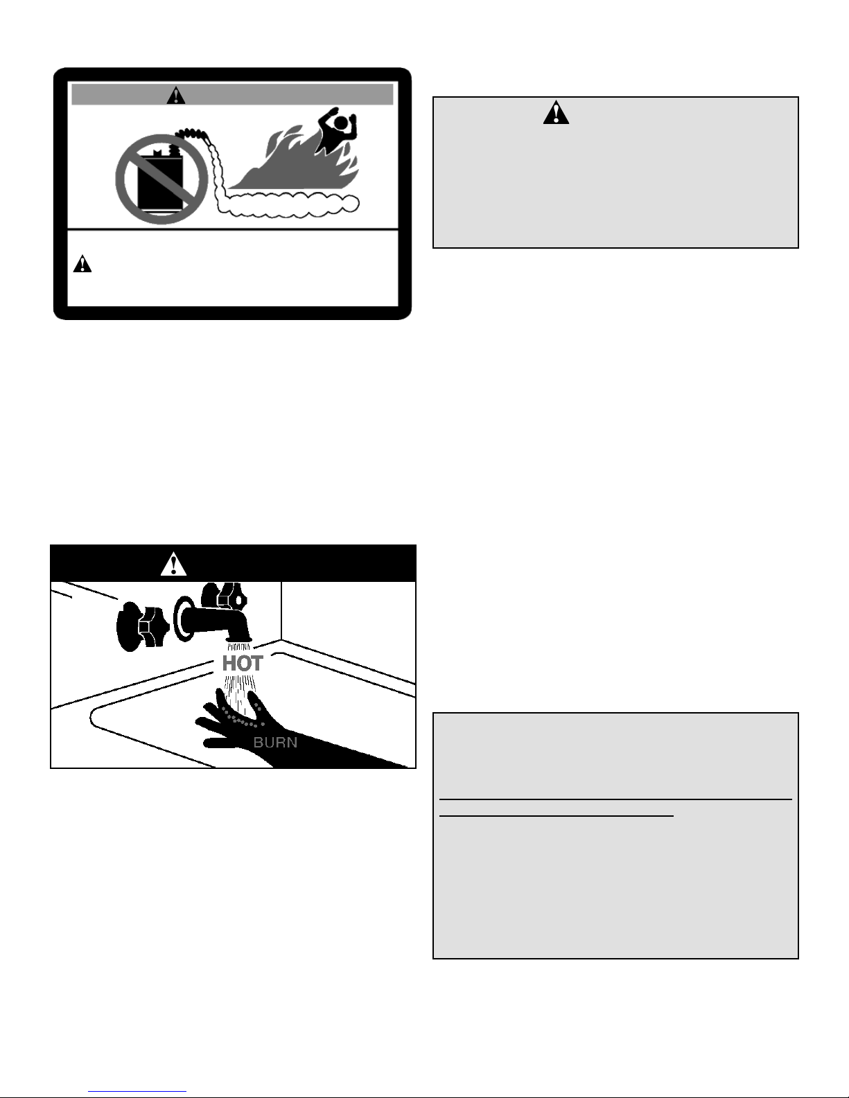
Safety Warning (Flammable Vapours)
WARNING
FLAMMABLES
FIRE AND EXPLOSION HAZARD
Can result in serious injury or death
Do not store or use gasoline or other flammable vapours and liquids
in the vicinity of this or any other appliance. Storage of or use of gasoline
or other flammable vapours or liquids in the vicinity of this or any other
appliance can result in serious injury or death.
There is a risk in using fuel-burning appliances such as
water heaters. Areas that may not be suitable for water
heater installation include those where flammable liquids,
gasoline, solvents, adhesives, etc., or engine-driven equipment or vehicles are stored, operated or repaired. Due to
the nature of air movement, flammable vapours can be carried some distance from the point of storage. The gas-fired
water heater igniter or main burner flame can ignite these
vapours causing a flashback, fire or explosion which may
result in serious personal injury or death, as well as severe
property damage.
Safety Warning (Scalding)
Flammable Vapours
DANGER
result in serious bodily harm or death from asphyxiation.
MAKE SURE THE FLOW OF COMBUSTION AND
VENTILATION AIR IS NOT RESTRICTED.
DANGER
Carbon Monoxide Warning
• Follow all vent system requirements by
the local authorities having jurisdiction
over your installation.
• Failure to do so can result in death, explosion or carbon monoxide poisoning.
Relief Valves (T&P)
All water heaters must be installed with a proper temperature and pressure relief valve. These valves must be
certified as meeting the requirements of the “Standard
for Temperature, Pressure, Temperature and Pressure
Relief and Vacuum Relief” CSA 4.4 in Canada. In the
United States “Relief Valves and Automatic Gas Shut-Off
Devices for Hot Water Supply Systems”, ANSI Z21.22 is
applicable.
If this water heater has been exposed to flooding, freezing,
fire or any unusual condition, do not put it into operation until
it has been inspected and approved by a qualified professional. THESE CONDITIONS CAN RESULT IN UNSEEN
INTERNAL DAMAGE which is not subject to warranty
coverage.
Backflow Prevention
Certain jurisdictions may require the installation of a backflow device (e.g., check valve) in the water supply line. Such
a device will require the use of a system expansion tank of
adequate size to control the thermal expansion generated
during the heating cycle. Consult your water supplier or local
plumbing authority.
Important: The supply water meter may have a built-in
check valve device. Contact your local water authority.
Hot water produced by this appliance can cause severe
burns due to scalding. The hazard is increased for young
children, the aged or the disabled where water temperatures
exceed 52°C (125°F). Use tempering valves (see Figure
11), in the hot water system to reduce the risk of scalding
at point-of-use such as lavatories, sinks and bathing facilities. Such precautions must be followed when this heater is
operated in combination with dishwashing or space heating
applications.
Safety Warning (Carbon Monoxide)
As with all fuel burning equipment, this heater requires an
adequate supply of air for combustion and ventilation. An
insufficient air supply can result in poor combustion or the
re-circulation of the exhaust flue gases. Such a condition
can cause soot build-up or present a fire hazard, and may
– 4 –
CAUTION
Hydrogen gas can be produced in a hot water system
served by this heater that has not been used for a
long period of time (generally two (2) weeks or more).
Hydrogen gas is extremely flammable and can ignite
when exposed to a spark or flame. To reduce the risk
of injury under these conditions, it is recommended that
the hot water faucet be opened for several minutes at the
kitchen sink before using any electrical appliance connected to the hot water system. Use caution in opening
faucets. If hydrogen is present, there will probably be an
unusual sound such as air escaping through the pipe as
the water begins to flow. There should be no smoking or
open flame near the faucet at the time it is open.
III) INSTALLATION
Unpacking the Water Heater
WARNING
Excessive Weight Hazard
• How and where to obtain combustion and ventilation air
• Routing and support of the vent piping.
• Position of water supply and placement of water piping
• Floor drain and service.
Use two or more people to move and install
water heater. Failure to do so can result in
back or other injury.
Important: Do not remove any permanent instructions,
labels or the rating plate from the outside of the water heater
or on the inside of panels.
1. Move the water heater to the location of installation
before removing the exterior packaging.
2. Remove exterior packaging and place installation components aside.
3. Inspect all parts for damage prior to installation and
start-up.
4. Completely read and understand all instructions before
attempting to assemble and install this product.
If you observe damage to the water heater or any of its components, DO NOT ASSEMBLE OR INSTALL IT OR MAKE
ANY ATTEMPT TO FIX THE DAMAGED PART(S). Contact
the place of purchase for further instructions.
5. After installation, dispose of packaging material in the
proper manner.
Location Requirements
IMPORTANT:
This water heater must be installed strictly in accordance
with the instructions enclosed, and local electrical, fuel
and building codes. It is possible that connections to the
water heater, or the water heater itself, may develop leaks.
IT IS THEREFORE IMPERATIVE that the water heater be
installed so that any leakage of the tank or related water
piping is directed to an adequate drain in such a manner
that it cannot damage the building, furniture, floor covering, adjacent areas, lower floors of the structure or other
property subject to water damage. This is particularly
important if the water heater is installed in a multi-story
building, on finished flooring or carpeted surfaces. THE
MANUFACTURER WILL NOT ASSUME ANY LIABILITY
for damage caused by water leaking from the water heater,
pressure relief valve, or related fittings. Select a location
as centralized within the piping system as possible. In any
location selected, it is recommended that a suitable drain
pan be installed under the water heater. This pan must
limit the water level to a MAXIMUM depth of 45mm (1 3/4
in.) and have a diameter that is a minimum of 50mm (2
in.) greater than the diameter of the water heater. Suitable
piping shall connect the drain pan to a properly operating
floor drain. When used with a fuel-fired heater, this drain
pan must not restrict combustion air flow.
Note: Before installing this water heater, consideration and
planning must be given to the following details:
In Earthquake Zones
Note: The water heater must be braced, anchored, or
strapped to avoid moving during an earthquake. Contact
local utilities for code requirements in your area.
Note: REVIEW SAFETY WARNINGS FOUND IN THE
FRONT OF THIS MANUAL BEFORE PROCEEDING
Clearances and Accessibility
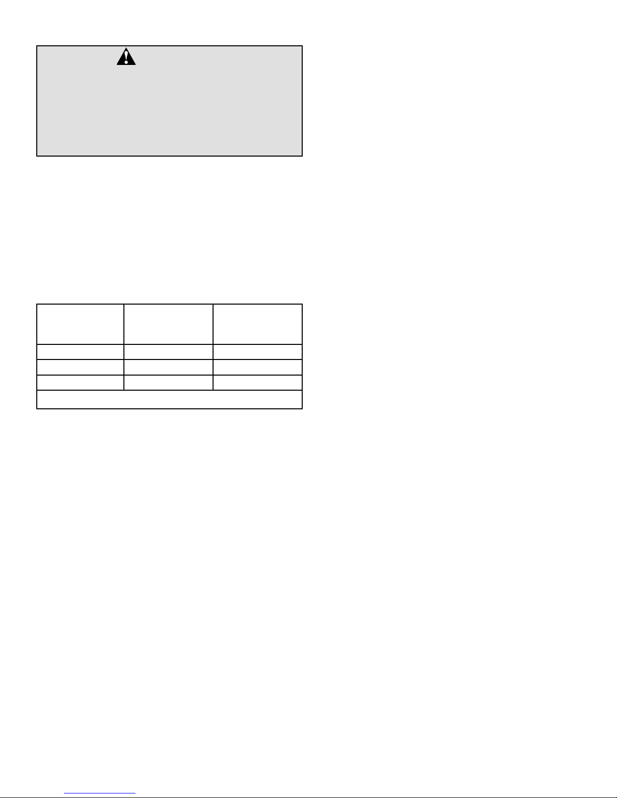
Specific clearance locations are shown in Figure 3. A minimum of 600mm (24 in.) of front clearance shall be provided
for inspection and service. We recommend that 0.9m (36 in.)
above be maintained for serviceability.
Locate the water heater such that all controls are easily
accessible, and the rating plate is visible.
Clearance to combustibles varies by model. Refer to rating
plate to confirm clearances.
Heaters with a volume of 19 gallons through 50 gallons and
60 gallon (standard input) must have the following minimum
clearances to combustibles:
Front 102mm (4 in.)
Sides and Rear 25mm (1 in.)
Top 203mm (8 in.)
Flue 152mm (6 in.)
JW6058 and G6058 (high input) series heaters must have
the following minimum clearances to combustibles:
Front 127mm (5 in.)
Sides and Rear 25mm (1 in.)
Top 203mm (8 in.)
Flue 152mm (6 in.)
• Location and Clearances.
• Access for gas supply; See “Gas Supply”.
– 5 –
supply; See “Air Requirements”.
for hot and cold water; See “Water Supply”.
45mm
(1 3/4 in.)
MAX
AT LEAST 50mm (2 in.)
GREATER THAN THE
DIAMETER OF THE
WATER HEATER.
Figure 1 Typical Drain Pan Installation
PIPE TO
ADEQUATE
DRAIN
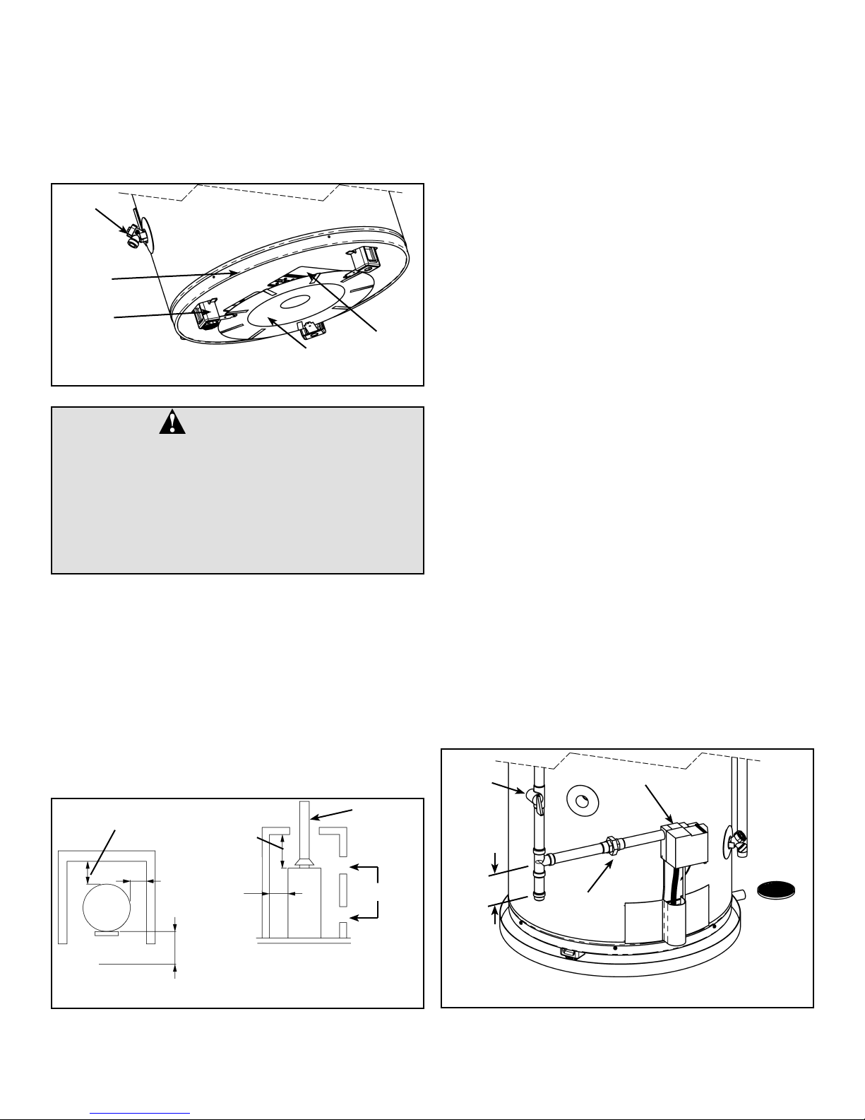
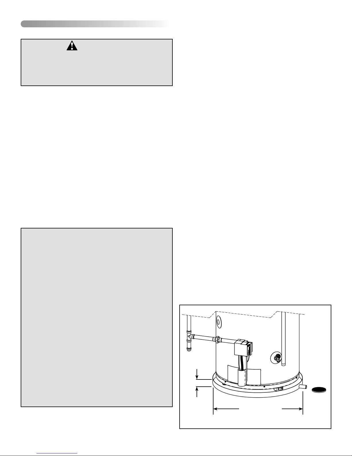
The 60 gallon heater is equipped with a Heat Reflector
Shield (see Figure 2). This Shield reflects heat from the
High-input heaters to prevent damage to combustible floors.
The Shield is held in place by three (3) tabs that rest on the
inside of the legs of the water heater. Ensure the Shield is
positioned horizontally (parallel to the bottom of the heater)
and in the designated position of 38mm (1.5 in.) below the
flame-arrestor.
DRAIN
VALV E
BOTTOM
PAN
LEG
FLAME
HEAT SHIELD
ARRESTOR
Figure 2 Heat Shield Installation (60 gallon only)
WARNING
Do not install directly on carpet. Instead, place the
water heater on a metal or wood panel extending a
minimum of 75mm (3 in.) from all sides. In alcoves
or closets, cover the carpet completely. Ensure this
panel is capable of supporting the weight of this
heater when filled with water.
FAILURE TO PROPERLY INSTALL THIS HEATER MAY
RESULT IN A FIRE HAZARD.
The water heater shall be located in an area not subject
to freezing temperatures. Water heaters located in unconditioned spaces (e.g., attics, basements, etc.) may require
insulation of the water and drain piping to protect against
freezing. Proper ventilation needs to be provided for water
heaters installed in unconditioned spaces (e.g., attics, basements, etc.) in order to avoid an event where air temperature exceeds 42°C (108°F). The drain and controls must be
easily accessible for operation and service. Maintain proper
clearances as specified on the data plate.
Ensure that the water heater is level. This heater may be
installed in a closet or alcove and is certified for operation
on a combustible floor.
VENT
BACK 25mm (1 in.)
TOP TO CEILING
200mm (8 in.)
affect the proper operation of the water heater. Special
attention must be given to conditions these devices may
create. Flow reversal of flue gases may cause an increase
of carbon monoxide inside of the dwelling, as shown in
Figure 7.
If the water heater is located in an area that is subject to
an excessive amount of lint, dirt or oil, it may be necessary
to clean the flame arrestor periodically (see “Maintenance”
section).
Important: It is always recommended that a suitable drain
pan be installed under the water heater to protect the area
from water damage resulting from normal condensation, a
leaking tank or piping connections. Refer to Figure 1. Under
no circumstances is the manufacturer to be held responsible
for any water damage in connection with this water heater.
Gas Supply
Install the gas piping as shown in Figure 4. Use only new
pipe and fittings with clean-cut threads. Sealing compounds
used on the pipe threads shall be approved for use with
natural and propane gas.
Use gas piping of adequate sizing to ensure gas input.
Gas piping material must be approved for use with natural gas and propane fuels. All piping must comply with all
local codes and with the latest edition of “Natural Gas
and Propane Installation Code” CSA-B149.1 in Canada,
“National Fuel Gas Code” ANSI Z223.1 (NFPA 54) in the
U.S.A. The final connection to the water heater is made
using 1/2” NPT.
Before connecting to the gas service, check that a properly
sized gas meter and regulator are available to service the
water heater. If other appliances are using the same meter
and regulator, ensure that the capacity of the meter and
regulator matches that of the combined input of all appliances connected to it.
DO NOT tamper with the gas control/thermostat, igniter,
thermocouple, or temperature and pressure relief valve.
Tampering voids all warranties. Only a qualified service
technician should service these components.
MANUAL
GAS
SHUT-OFF
GAS CONTROL/THERMOSTAT
SIDES
25mm
(1 in.)
SIDES
AND BACK
25mm (1 in.)
FRONT 600mm
(24 in.) MIN.
FOR SERVICE
Figure 3 Minimum Clearance Locations
Do not locate the water heater near an air-moving device.
The operation of air-moving devices such as exhaust fans,
ventilation systems, clothes dryers, fireplaces, etc., can
– 6 –
AIR INTAKE
75mm (3 in.)
GROUND-
JOINT UNION
Figure 4 Recommended Gas Piping
Gas Pressure
WARNING
Exposure to a higher gas supply pressure
may cause damage to the control, resulting
in explosion or fire. Consult your local gas
supplier and gas authorities. DO NOT PUT
INTO SERVICE IF OVER-PRESSURIZATION
HAS OCCURRED.
The Manufacturer recommends that the gas supply pressure, as measured on the inlet side of the water heater
control, be set at 7.0 in. w.c. (1.7 kPa) for natural gas and
11.0 in. w.c. (2.7 kPa) for propane gas. The above pressures
must be measured during water heater operation.
The gas control supplied with this water heater is designed
for a maximum inlet pressure of 0.5 psi (14 in. w.c.). Do
not exceed this limit. The Flame GuardTM safety system is
designed to operate within the pressure ranges shown in
Table 1. Rated manifold pressures are indicated on the rating plate of the water heater.
Rated Manifold
Pressure.
in. w.c. (kPa)
10 (2.48) 9.2 (2.28) 10.2 (2.53)
5 (1.24) 4.5 (1.11) 5.1 (1.26)
4 (0.99) 3.6 (0.89) 4.4 (1.09)
Min. Manifold
Pressure.
in. w.c. (kPa)
Max. Manifold
Pressure.
in. w.c. (kPa)
Gas line purging
Gas line purging is required to eliminate air from the piping
system. Purging should be performed by persons experienced in this type of gas service in compliance with the code
having jurisdiction. Do not purge in confined areas or space
where ignition may occur. To avoid risk of fire or explosion
ensure the area is well ventilated and all sources of ignition
are de-activated. Contact your local gas authority for local
requirements.
Gas Leak Testing
Important: This water heater and its gas connection must
be tested for leaks before placing the appliance in operation.
Perform a leak test at normal gas pressure. If the applicable
code(s) require the gas lines to be tested at a pressure of 14
in. w.c. (3.5 kPa) or greater, the water heater and its manual
shut-off valve must be disconnected from the gas supply
piping system and the line capped. Test all connections of
the gas system with a chloride-free soap and water solution
or equivalent leak test liquid. Bubbles will indicate leaks.
Never use a match or open flame to test for gas leaks. A fire
or explosion could result. If leaks exist repair as required
and retest.
DO NOT light the burner before the tank is filled with water
and you have confirmed that there are no leaks in the piping
and connections.
Table 1 Manifold Pressure
– 7 –
Air Requirements
Important: Air for combustion and ventilation must not
come from a corrosive atmosphere. Any failure due to corrosive elements in the atmosphere is excluded from warranty
coverage.
Installations in or for certain places including, but not limited
to, those listed below will require outdoor air for combustion
due to chemical exposure:
• Beauty shops
• Photo processing labs
• Buildings with indoor pools
• Water heaters installed in laundry, hobby or craft rooms
• Water heaters installed near chemical storage areas
(12 in.) equals 450mm (18 in.) as shown in Figure 5 (b).
All exterior vent openings are to be at least 300mm (12
in.) above the ground and clear of snow levels.
(a)
PERMANENT
OPENINGS
CONFINED
SPACE
UNCONFINED
SPACE
In such circumstances, outdoor combustion air may reduce,
but will not eliminate, the presence of corrosive chemicals in
the air. Combustion air must be free of acid-forming chemicals such as sulfur, fluorine and chlorine. These elements
are found in aerosol sprays, detergents, bleaches, cleaning
solvents, air fresheners, paint and varnish removers, refrigerants and many other commercial and household products.
When burned, vapours from these products form highly
corrosive acid compounds. These products should not be
stored or used near the water heater or air inlet.
The area in which the heater is located is classified as either
“an unconfined space” or “a confined space”.
An unconfined space is defined as a space having a vol-
ume not less than 50 cubic feet per 1000 BTU/hour (4.8
cubic metres per kilowatt) of combined input rating of all
appliances using the space. Adjacent open rooms may be
included as part of the unconfined space, provided there are
no closeable doors between these rooms. An example of
this is an open basement.
A confined space is one smaller than described above.
For buildings using tight construction (newer and renovated
structures), the air supply shall be introduced from the
outdoors, regardless of whether the space is confined or
unconfined.
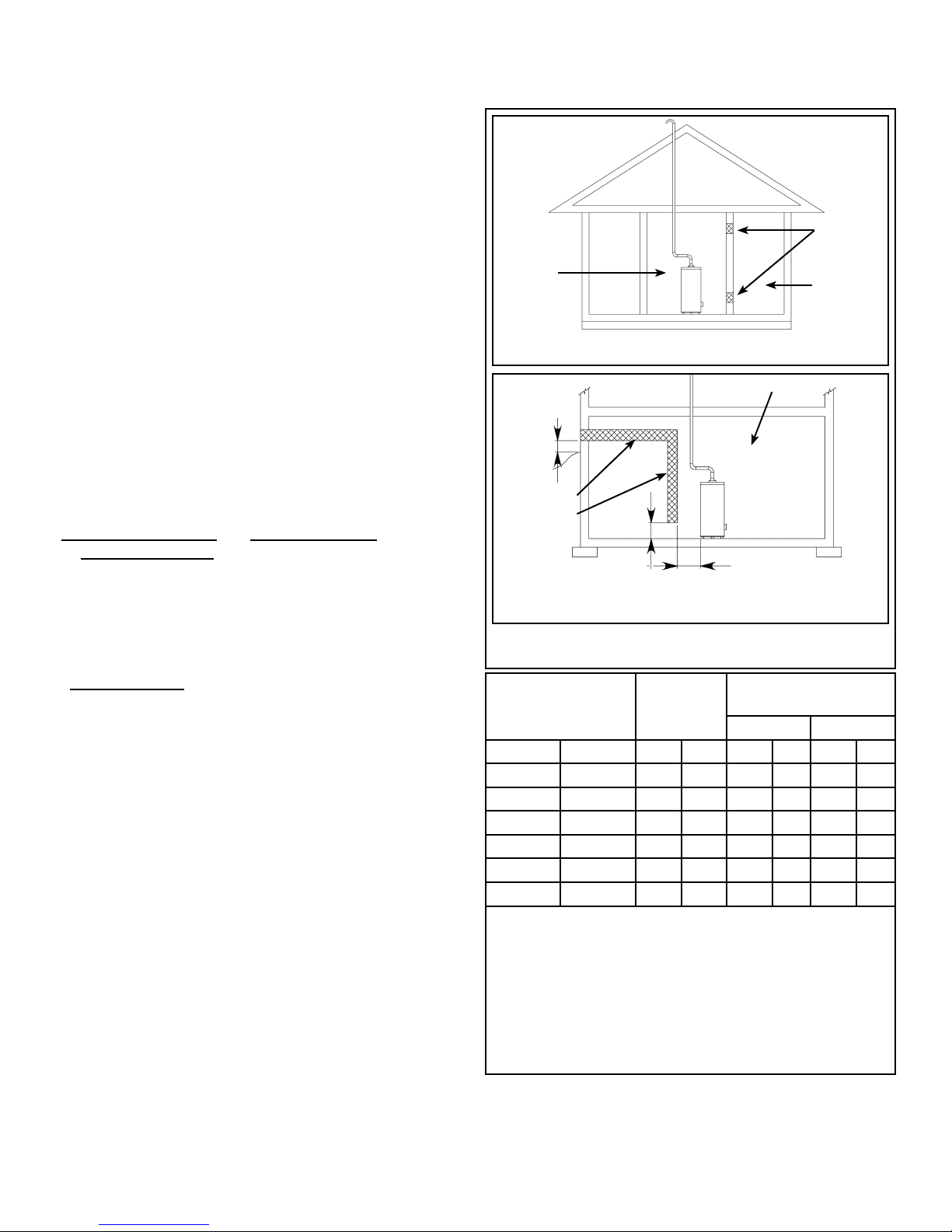
Confined Space Air Requirements for
Canadian Installations
Refer to Figure 5 (a), or (b), and Table 2 for proper sizing
and location of combustion air ducts and openings. CHECK
LOCAL CODES.
(a). Two permanent openings shall be provided connect-
ing the confined space (e.g., closet, small room) with
the unconfined space. Each opening shall have a free
area of one square inch per 1,000 BTU/hour input (22
cm²/kW) of all appliances in the confined space. The
top opening shall be located as close to the ceiling as
practical but never lower than the top of the heater (see
Figure 5 (a)). The bottom opening shall be located neither more than 450mm (18 in.), nor less than 150mm (6
in.), above floor level.
(b). When using a single air supply, the duct shall terminate
within 300mm (12 in.) above and within 600mm (24 in.)
horizontally of the burner level of the appliance having
the largest input. For example: if the water heaters’
burners are 150mm (6 in.) from the floor, plus 300mm
– 8 –
EQUIPMENT LOCATED IN CONFINED SPACES;
ALL AIR FROM INSIDE THE BUILDING.
300mm
(b)
(12 in.)
(MIN)
GRADE
COMBINATION
COMBUSTION/
VENTILATION
AIR DUCT
BASEMENT INSTALLATION, EQUIPMENT LOCATED
IN CONFINED SPACES; ALL AIR FROM OUTDOORS
450mm (18 in.)
CONFINED
SPACE
600mm (24 in.)
Figure 5 Combustion Air Supply Openings And Ducts
(Can.)
Combined Input of
All Appliances in
Confined Space*
Required
Free Area
Acceptable Round
Duct Size Diameter
A** B***
BTU/h (kW/hr) cm2in.2mm in. mm in.
25,000 8 45 7 76 3 100 4
50,000 15 45 7 76 3 100 4
75,000 23 70 11 100 4 125 5
100,000 30 90 14 100 4 125 5
125,000 37 120 18 125 5 150 6
150,000 45 140 22 125 5 150 6
* All appliances refers to, and includes, those appliances
using the same air source (e.g. water heater, furnace,
boiler, clothes dryer etc.).
** Maximum allowable length of ductwork listed in column
A is 6.1 equivalent metres (20 ft.).
*** Maximum allowable length of ductwork listed in column
B is 15.2 equivalent metres (50 ft.)
Table 2 Air Supply Sizing (Can.)
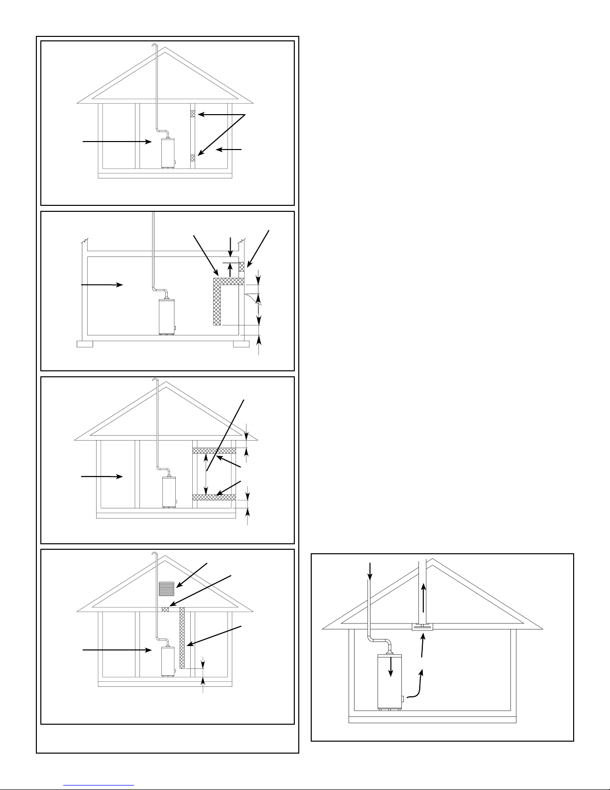
(a)
Confined Space Air Requirements for
U.S. Installations
Refer to Figure 6 (a), (b), (c) or (d) for proper sizing and
location of combustion air ducts and openings. CHECK
LOCAL CODES.
CONFINED
SPACE
(b)
CONFINED
SPACE
(c)
CONFINED
SPACE
UNCONFINED
EQUIPMENT LOCATED IN CONFINED SPACES;
ALL AIR FROM INSIDE THE BUILDING.
COMBUSTION
AIR DUCT
BASEMENT INSTALLATION, EQUIPMENT LOCATED
IN CONFINED SPACES; ALL AIR FROM OUTDOORS
EQUIPMENT LOCATED IN CONFINED
SPACES; ALL AIR FROM OUTDOORS.
300mm
(12 in.)
OUTDOORS
AIR DUCT
300mm (12 in.)
VENTILATION
COMBUSTION
300mm (12 in.)
PERMANENT
OPENINGS
SPACE
PERMANENT
VENTILATION
AIR.
300mm
(12 in.)
ABOVE
GRADE
OR
SNOW
LINE
GRADE
300mm
(12 in.)
(a) Equipment located in confined spaces; all air from
inside the building.
Two permanent openings shall be provided connect-
ing the confined space (e.g., closet, small room) with
the unconfined space. Each opening shall have a free
area of one square inch per 1,000 BTU/hour input (22
cm²/kW) of all appliances in the confined space, but not
less than 100 square inches (645 cm²). The top opening shall commence within 300mm (12 in.) of the top of
space and the bottom opening shall commence within
300mm (12 in.) of the bottom of the enclosure.
(b) Basement installation, equipment located in con-
fined spaces; all air from outdoors.
When supplying air directly from the outdoors, each
opening shall have a minimum free area of one square
inch per 4,000 BTU/hour input (5.5 cm²/kW) of total
input rating of all appliances in the confined space. The
inlets shall be a minimum of 300mm (12 in.) above the
grade (snow) line. The top opening shall commence
within 300mm (12 in.) of the top of the confined space.
(c) Equipment located in confined spaces; all air from
outdoors.
When supplying air directly from the outdoors using
horizontal ducting, each opening shall have a free
minimum area of one square inch per 2,000 BTU/hour
(11 cm²/kW) of total input rating of all appliances in the
confined space.
(d) Equipment located in confined spaces; all air from
outdoors through ventilated attic.
When supplying air directly through vertical ducting,
each opening shall have a free minimum area of one
square inch per 4,000 BTU/hour (5.5 cm²/kW) of total
input rating of all appliances in the confined space.
(d)
CONFINED
SPACE
EQUIPMENT LOCATED IN CONFINED SPACES; ALL AIR
FROM OUTDOORS THROUGH VENTILATED ATTIC.
ATTIC LOUVERS TO OUTDOORS
Figure 6 Combustion Air Supply Openings And Ducts
(U.S.A.)
– 9 –
OUTLET
AIR
INLET AIR
300mm (12 in.)
DUCT
EXHAUST
REVERSE
FLOW OF
GASES
Figure 7 Air Moving Devices
FAN
Exhaust Venting
Vent Pipe System
This water heater is a Category 1, non-direct vented appliance. The vent pipe must be sized and installed in accordance with all local and provincial or state codes and with
the latest edition of “Natural Gas and Propane Installation
Code” CSA-B149.1 in Canada, “National Fuel Gas Code”
ANSI Z223.1 (NFPA 54) in the U.S.A.
Check for proper vent size
It is possible that the existing venting system was sized, for
a previous installation, through a common vent. Such an
arrangement is appropriate for venting two appliances such
as the original water heater and a standard vent furnace.
If this is true and the second appliance has been removed
from the existing venting system (such as when the furnace
has been upgraded to a power vent type), the venting system is now supplying only one appliance. This condition is
commonly referred to as “orphaning” the water heater and
the venting system must be properly resized for a single
appliance. Improper sizing can cause a number of undesirable and potentially unsafe results including spillage of the
products of combustion into the room, poor combustion,
excessive condensation, pilot outage or delayed ignition.
The vent pipe must not be obstructed so as to prevent the
removal of exhaust gases to the outside atmosphere.
Note: The horizontal section of the vent must slope up
21mm per metre (1/4 in. per foot), (see Figure 8).
CSA/U.L. recognized fuel gas and carbon monoxide (CO)
detectors are recommended in all applications and should
be installed using the manufacturer’s instructions and local
codes, rules or regulations.
Important: If you lack the necessary skills required to properly install this venting system, you should not proceed, but
enlist the help of a qualified service technician.
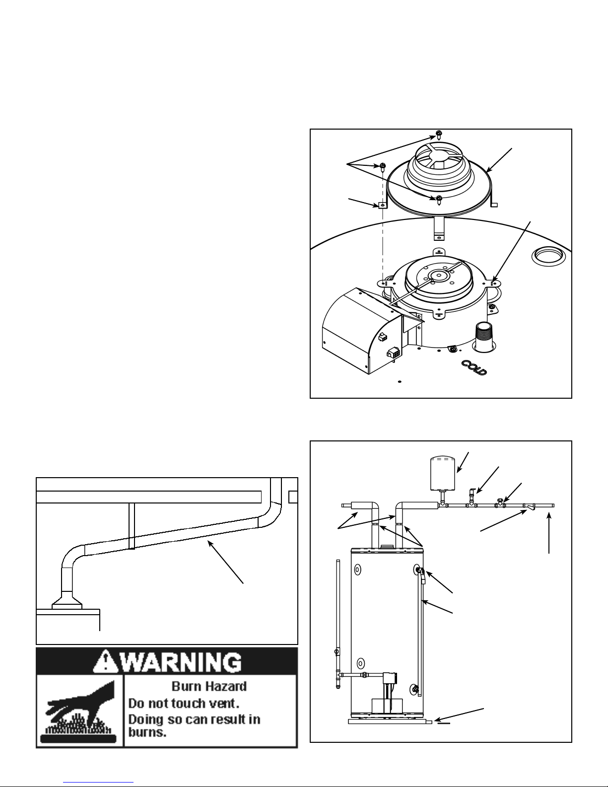
Drafthood Installation
Hook the tab leg of the drafthood into the slot in the heater’s
top or the flue damper if the heater is equipped with a flue
damper. Align the remaining legs with the hole/dimples and
secure the drafthood to the top with three screws as shown
in Figure 9. Do not alter the drafthood in any way. If you are
replacing an existing water heater be sure to use the new
drafthood supplied with the water heater.
DRAFTHOOD
SCREW
TAB LEG
SLOT
Figure 9 Drafthood Installation
Water Supply
Piping Installation
IN A CLOSED SYSTEM USE EITHER:
HOT WATER
OUTLET
1.THERMAL EXPANSION TANK
2.PRESSURE RELIEF VALVE
COLD WATER
INLET VALVE
SLOPE UP 21mm PER METRE
(1/4 in. PER ft) MIN.
Figure 8 Vent System
– 10 –
PIPE
INSULATION
UNION
PRESSURE REDUCING
VALVE WITH BYPASS
TEMPERATURE AND
PRESSURE RELIEF VALVE
DISCHARGE LINE 300mm
(12 in.) MAX (CANADA)
OR 150mm (6 in.) MAX
(U.S.A.) ABOVE DRAIN
MASSACHUSETTS:
INSTALL A VACUUM
RELIEF IN COLD WATER
LINE PER SECTION
19MGL 142
DRAIN LINE 19mm
(3/4 in.) ID MIN
Figure 10 Example Of Water Piping Installation
COLD WATER
INLET
 Loading...