

John Wood RESIDENTIAL GAS WATER HEATERS Installation And Operating Manual
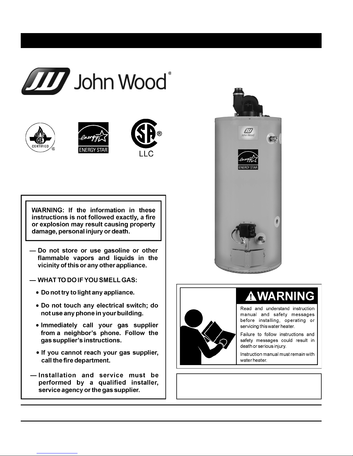
Installation and Operating Manual
RESIDENTIAL GAS WATER HEATERS
POWER DIRECT VENT GAS MODELS
WITH HOT SURFACE IGNITION
NOT FOR USE IN MANUFACTURED (MOBILE) HOMES
ALL TECHNICAL AND WARRANTY QUESTIONS: SHOULD BE DIRECTED TO THE LOCAL DEALER FROM WHOM THE WATER HEATER WAS
PURCHASED. IF YOU ARE UNSUCCESSFUL, PLEASE CONTACT THE COMPANY LISTED ON THE RATING PLATE ON THE WATER HEATER.
KEEP THIS MANUAL IN THE POCKET ON HEATER FOR FUTURE REFERENCE
WHENEVER MAINTENANCE ADJUSTMENT OR SERVICE IS REQUIRED.
1410 328126-000
• For Your Safety •
AN ODOURANT IS ADDED TO THE GAS USED
BY THIS WATER HEATER.

TABLE OF CONTENTS
SAFE INSTALLATION, USE AND SERVICE . . . . . . . . . . .3
GENERAL SAFETY . . . . . . . . . . . . . . . . . . . . . . . . . . . . . .4
INTRODUCTION . . . . . . . . . . . . . . . . . . . . . . . . . . . . . . . . 6
Qualifi ed Installer Or Service Agency . . . . . . . . . . . . 6
Preparing For The Installation. . . . . . . . . . . . . . . . . . 6
TYPICAL INSTALLATION. . . . . . . . . . . . . . . . . . . . . . . . . .7
Get To Know Your Water Heater -
Gas Models (List Referencing Figures 1-5) . . . . . . . 7
Replacement Parts And Deliming Products . . . . . . . 8
Combo Heating Inlet And Outlet Side Taps . . . . . . . . 8
Water Piping - Mixing Valve Usage . . . . . . . . . . . . . . 9
Mixing Valves
Water Heater Operation . . . . . . . . . . . . . . . . . . . . . 10
Electrical Requirements & Wiring Diagram . . . . . . . .11
SAFETY LOCKOUTS. . . . . . . . . . . . . . . . . . . . . . . . . . . . 12
High Limit Controls (Energy Cut Off). . . . . . . . . . . . 12
Thermostat/Water Temperature
Blower High Limit Switch
Blower Air Pressure SwitchEs. . . . . . . . . . . . . . . . . 12
LOCATING THE NEW WATER HEATER. . . . . . . . . . . . .13
Facts To Consider About The Location . . . . . . . . . . 13
Clearances To Combustibles
Floors With Carpeting
Clearances For Servicing
High Ambient Temperature Installations . . . . . . . . . 14
Important Notes and Warnings
Air Requirements . . . . . . . . . . . . . . . . . . . . . . . . . . 15
INSTALLING THE NEW WATER HEATER . . . . . . . . . . . 16
Water Piping . . . . . . . . . . . . . . . . . . . . . . . . . . . . . . 16
Space Heating And Potable Water Systems . . . . . . 16
Combo Heating . . . . . . . . . . . . . . . . . . . . . . . . . . . . 17
System Requirements
Installation
Closed Water Systems . . . . . . . . . . . . . . . . . . . . . . 18
Thermal Expansion . . . . . . . . . . . . . . . . . . . . . . . . . 18
Temperature-Pressure Relief Valve. . . . . . . . . . . . . 19
T&P Valve Discharge Pipe Requirements:
Temperature-Pressure Relief Valve And
Pipe Insulation
High Altitude Installation . . . . . . . . . . . . . . . . . . . . . 20
Gas Piping. . . . . . . . . . . . . . . . . . . . . . . . . . . . . . . . 20
Sediment Traps. . . . . . . . . . . . . . . . . . . . . . . . . . . . 21
Filling The Water Heater . . . . . . . . . . . . . . . . . . . . . 22
Venting . . . . . . . . . . . . . . . . . . . . . . . . . . . . . . . . . . 23
Termination Clearances (Sidewall) . . . . . . . . . . . . . 24
Side Wall Vent Terminal Installation
Roof Vent Terminal Installation
Concentric Vent Termination Kit Installation
Multiple Concentric Vent Installations
Vent Pipe Length
Vent Pipe Termination
Venting Terminations And Sizing
Vent Screen Installation
Vent Pipe Material
Vent Pipe Installation
Vent Pipe Runs
Vent Terminal Installations
Blower Assembly Installation. . . . . . . . . . . . . . . . . . 30
Vent/Intake Pipe Connections To Blower/Air Duct
Coupling Installations According To Vent Sizes
Sound Suppressor . . . . . . . . . . . . . . . . . . . . . . . . . 33
Side Wall Vent Installation
Vertical Vent Installation
Installation Checklist . . . . . . . . . . . . . . . . . . . . . . . . 34
LIGHTING INSTRUCTIONS. . . . . . . . . . . . . . . . . . . . . . .35
OPERATING THE TEMPERATURE
CONTROL SYSTEM . . . . . . . . . . . . . . . . . . . . . . . . . . . . 36
Gas Control Valve/Thermostat . . . . . . . . . . . . . . . . 37
FOR YOUR INFORMATION. . . . . . . . . . . . . . . . . . . . . . . 38
Start Up Conditions . . . . . . . . . . . . . . . . . . . . . . . . . 38
Condensate
Smoke/Odour
Strange Sounds
Operational Conditions . . . . . . . . . . . . . . . . . . . . . . 38
Smelly Water
“Air” In Hot-Water Faucets . . . . . . . . . . . . . . . . . . . 38
PERIODIC MAINTENANCE. . . . . . . . . . . . . . . . . . . . . . . 39
General Upkeep . . . . . . . . . . . . . . . . . . . . . . . . . . . 39
Venting System Inspection . . . . . . . . . . . . . . . . . . . 39
Burner Operation And Inspection . . . . . . . . . . . . . . 39
Combustion Chamber And Burner Cleaning. . . . . . 40
Housekeeping . . . . . . . . . . . . . . . . . . . . . . . . . . . . . 40
Temperature-Pressure Relief Valve Test . . . . . . . . . 40
Draining And Flushing. . . . . . . . . . . . . . . . . . . . . . . 41
To Drain The Water Heater Storage Tank:
To Flush The Water Heater Storage Tank:
Anode Rod Maintenance. . . . . . . . . . . . . . . . . . . . . 42
LEAKAGE CHECKPOINTS . . . . . . . . . . . . . . . . . . . . . . .43
Service . . . . . . . . . . . . . . . . . . . . . . . . . . . . . . . . . . 43
REFERENCE PARTS LISTING . . . . . . . . . . . . . . . . . . . .44
TROUBLESHOOTING GUIDELINES. . . . . . . . . . . . . . . .46
Lockouts . . . . . . . . . . . . . . . . . . . . . . . . . . . . . . . . . 46
Soft Lockout
Hard Lockout
Resetting The Heater Control . . . . . . . . . . . . . . . . . 46
Ignition State And Timing . . . . . . . . . . . . . . . . . . . . 46
System Status And Error Codes . . . . . . . . . . . . . . . 47
Reading The LED Flash Sequence. . . . . . . . . . . . . 47
Corrective Actions . . . . . . . . . . . . . . . . . . . . . . . . . . 48
Other Symptoms . . . . . . . . . . . . . . . . . . . . . . . . . . . 50
NOTES . . . . . . . . . . . . . . . . . . . . . . . . . . . . . . . . . . . . . . .51
2 www. johnwoodwaterheaters .com 328126-000
SAFE INSTALLATION, USE AND SERVICE
Your safety and the safety of others is extremely important in the installation, use and servicing of this water heater.
Many safety-related messages and instructions have been provided in this manual and on your own water heater to warn you
and others of a potential injury hazard. Read and obey all safety messages and instructions throughout this manual. It is very
important that the meaning of each safety message is understood by you and others who install, use or service this water heater.
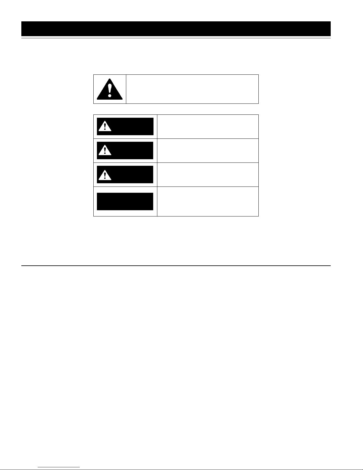
This is the safety alert symbol. It is used to alert you
to potential personal injury hazards. Obey all safety
messages that follow this symbol to avoid possible
injury or death.
DANGER indicates an imminently
DANGER
WARNING
CAUTION
CAUTION
hazardous situation which, if not avoided,
will result in death or injury.
WARNING indicates a potentially
hazardous situation which, if not avoided,
could result in death or injury.
CAUTION indicates a potentially
hazardous situation which, if not avoided,
could result in minor or moderate injury.
CAUTION used without the safety alert
symbol indicates a potentially hazardous
situation which, if not avoided, could
result in property damage
All safety messages will generally tell you about the type of hazard, what can happen if you do not follow the safety message
and how to avoid the risk of injury.
This product is certifi ed to comply with a maximum weighted average of 0.25% lead content as required in some areas.
IMPORTANT DEFINITIONS
Qualifi ed Installer: A qualifi ed installer must have ability equivalent to a licensed tradesman in the fi elds of plumbing,
air supply, venting and gas supply, including a thorough understanding of the requirements of the National Fuel Gas
Code as it relates to the installation of gas fi red water heaters. The qualifi ed installer must also be familiar with the
design features and use of fl ammable vapor ignition resistant water heaters and have a thorough understanding of this
Installation and Operating manual.
Service Agency: A service agency also must have ability equivalent to a licensed tradesman in the fi elds of plumbing, air
supply, venting and gas supply, including a thorough understanding of the requirements of the National Fuel Gas Code
as it relates to the installation of gas fi red water heaters. The service agency must also have a thorough understanding
of this Installation and Operating manual, and be able to perform repairs strictly in accordance with the service guidelines
provided by the manufacturer.
Gas Supplier: The Natural Gas or Propane Utility or service who supplies gas for utilization by the gas burning appliances
within this application. The gas supplier typically has responsibility for the inspection and code approval of gas piping
up to and including the Natural Gas meter or Propane storage tank of a building. Many gas suppliers also offer service
and inspection of appliances within the building.
328126-000 www. johnwoodwaterheaters .com 3
GENERAL SAFETY
4 www. johnwoodwaterheaters .com 328126-000
GENERAL SAFETY
WARNING
Breathing Hazard - Carbon Monoxide Gas
• Install vent system in accordance with codes.
• Do not operate water heater if flood damaged.
• For operation above 3,079 m (10,100’), a high
altitude orifice must be installed.
• Do not operate if soot buildup is present.
• Do not obstruct water heater air intake with
insulating jacket.
• Do not obstruct blower air intake.
• Do not place chemical vapour emitting products
near water heater.
• Gas and carbon monoxide detectors are
available.
• No vent damper installation is compatible with
this power vented water heater.
Breathing carbon monoxide can cause brain damage or death.
Always read and understand instruction manual.
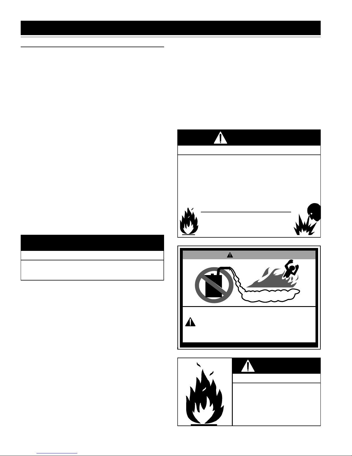
DANGER
FLAMMBLE
Vapours from flammable
liquids may explode and
catch fire causing death or
severe burns.
Do not use or store
flammable products such as
gasoline, solvents or adhesives in the same room or
area near the water heater.
Keep flammable products:
1. far away from heater,
2. in approved containers,
3. tightly closed and
4. out of children's reach.
Installation: Do not install the water heater where flammable
products will be stored or used.
Flammable Vapours
Water heater has a main
burner and hot surface igniter.
The hot surface igniter:
1. can be triggered at any
time and
2. the hot surface will ignite
flammable vapours.
Vapours:
1. cannot be seen,
2. are heavier than air,
3. go a long way on the floor
and
4. can be carried from other
rooms to the electrodes
by air currents.
328126-000 www. johnwoodwaterheaters .com 5

INTRODUCTION
Thank You for purchasing this water heater. Properly
installed and maintained, it should give you years of trouble
free service.
Abbreviations found in this Installation and Operating
manual:
• CSA - Canadian Standards Association
• ANSI - American National Standards Institute
• ASME - American Society of Mechanical Engineers
This gas-fi red water heater is design certifi ed by CSA
International, under Water Heater Standard ANSI
Z21.10.1 • CSA 4.1 or ANSI Z21.10.3 • CSA 4.3 (current
edition), as applicable.
QUALIFIED INSTALLER OR SERVICE AGENCY
Installation and service of this water heater requires ability
equivalent to that of a Qualifi ed Agency (as defi ned by
ANSI below) in the fi eld involved. Installation skills such
as plumbing, air supply, venting, gas supply and electrical
supply are required in addition to electrical testing skills
when performing service.
ANSI Z223.1 2006 Sec. 3.3.83: “Qualifi ed Agency” - “Any
individual, fi rm, corporation or company that either in
person or through a representative is engaged in and is
responsible for (a) the installation, testing or replacement
of gas piping or (b) the connection, installation, testing,
repair or servicing of appliances and equipment; that
is experienced in such work; that is familiar with all
precautions required and that has complied with all the
requirements of the authority having jurisdiction.”
If you are not qualifi ed (as defi ned by ANSI above) and
licensed or certified as required by authority having
jurisdiction to perform a given task, do not attempt to
perform any of the procedures described in this manual.
If you do not understand the instructions given in this
manual do not attempt to perform any procedures outlined
in this manual.
The installation must conform with these instructions
and local code authority having jurisdiction. In
absence of local codes, installation must comply with
current editions of the “Natural Gas and Propane
Installation Code” B149.1 and “Canadian Electrical
Code (CAN/CSA C22.1), Part I” . All documents are
available from:
Canadian Standards Association,
5060 Spectrum Way,
Mississauga, Ontario, Canada
L4W 5N6
2. The water heater, when installed, must be electrically
grounded in accordance with the local codes or in
the absence of local codes: current edition of the
“Canadian Electrical Code (CAN/CSA C22.1), Part
I” .
3. If after reading this manual you have any questions or
do not understand any portion of the instructions, call
the local gas utility or the manufacturer whose name
appears on the rating plate.
4. Carefully plan the place where you are going to put
the water heater. Correct combustion, vent action, and
vent pipe installation are very important in preventing
death from possible carbon monoxide poisoning and
fi res (see Figure 12). Examine the location to ensure
the water heater complies with the “Locating The New
Water Heater” section in this manual.
5. For installation in areas subject to earthquakes, this
water heater must be braced, anchored, or strapped to
avoid falling or moving during an earthquake. Contact
local utilities for code requirements in your area.
PREPARING FOR THE INSTALLATION
1. Read the “General Safety” section of this manual
fi rst and then entire manual carefully. If you don’t
follow safety rules, the water heater will not
operate properly. It could cause DEATH, SERIOUS
BODILY INJURY AND/OR PROPERTY DAMAGE.
This manual contains instructions for installation,
operation, and maintenance of the gas-fi red water
heater. It also contains warnings throughout the
manual that you must read and be aware of. All
warnings and instructions are essential to proper
operation of the water heater and your safety. Since
we cannot put everything on the fi rst few pages,
READ ENTIRE MANUAL BEFORE ATTEMPTING
TO INSTALL OR OPERATE THE WATER HEATER.
6 www. johnwoodwaterheaters .com 328126-000
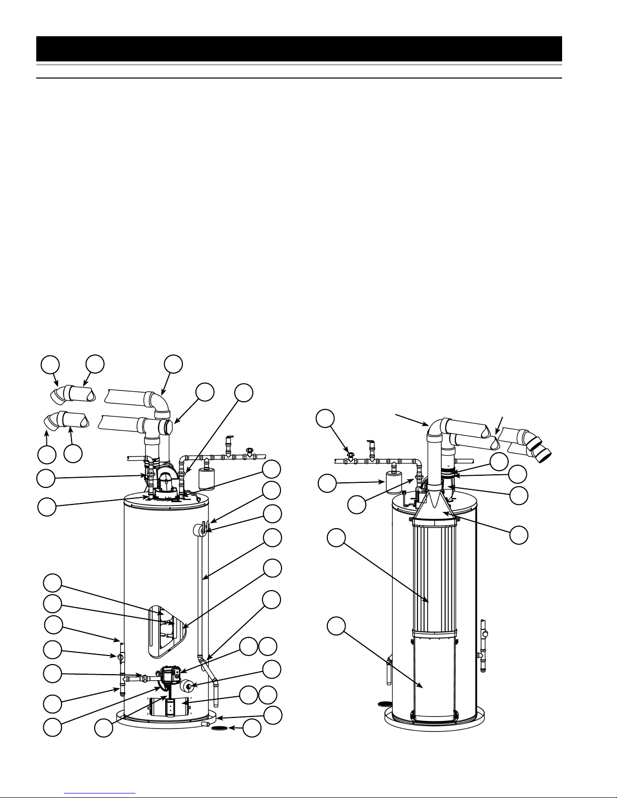
GET TO KNOW YOUR WATER HEATER - GAS MODELS (LIST REFERENCING FIGURES 1-5)
1 Termination Elbow with Rodent
Screen
2 *Vent Pipe
3 *Vent Pipe Elbow (long radius)
4 Sound Suppressor (Tee fi tting)
5 *Union (Di-electric water
connection)
6 Cold-Water Inlet Nipple/Diptube
7 **Combo Heating System Supply
Outlet (Optional)
8 T&P Valve
9 * Discharge Pipe
10 **Combo Heating System Return
Inlet (Optional)
11 Gas Control Valve/Thermostat
(Honeywell)
12 Gas Valve Electronic Control
Module And Cover (Honeywell)
13 Drain Valve
14 Outer Gas Door
15 Manifold Door Assembly (behind
outer door) (see Figure 3 &
Figure 4)
16 *Metal Drain Pan
17 *Floor Drain
1
2
TYPICAL INSTALLATION
18 Flexible Manifold Tube (see
Figure 3 & Figure 4)
19 ***Control Harness
20 *Sediment Trap
21 *Ground Joint Union (gas
connection)
22 *Main Manual Gas Shut-off Valve
23 *Gas Supply*
24 Anode (under cap)
25 Baffl e Assembly
26 Hot-Water Outlet Nipple/Anode
27 *Inlet Water Shut-off Valve
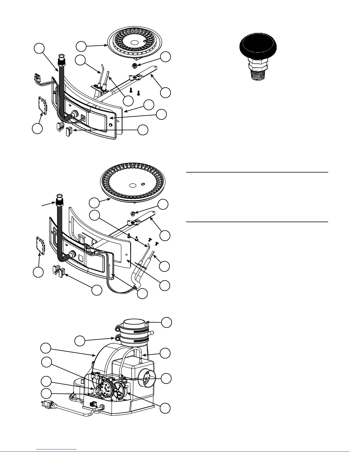
28 ****Rubber Coupling (see Figure 5)
29 Gear Clamp (see Figure 5)
30 ***Blower with Power Cord (see
Figure 5)
31 Air Duct Adapter
32 Air Inlet Snorkel
33 Air Duct
34 *Thermal Expansion Tank (see
“Closed Water Systems” and
“Thermal Expansion” sections)
35 Flame Sensor Rod (see Figure 3 &
Figure 4)
36 Sheet Metal Burner (see Figure 3 &
3
Figure 4)
37 Gas Orifi ce (see Figure 3 &
Figure 4)
38 Gas Manifold (see Figure 3 &
Figure 4)
39 Hot-Surface Igniter (see Figure 3 &
Figure 4)
Manifold Door Gasket (see Figure 3
40
& Figure 4)
41 Manifold Door (see Figure 3 &
Figure 4)
42 Two Piece Grommet With Clip (see
Figure 3 & Figure 4)
43 Viewport (see Figure 3 & Figure 4)
44 Air Tubing (Intake) (see Figure 5)
45 Blower High Limit Switch (see
Figure 5)
46 Intake Air Pressure Switch (NC)
(inside box) (see Figure 5)
47 Capacitor (see Figure 5)
48 Air Tubing (Exhaust) (see Figure 5)
49 Exhaust Air Pressure Switch (NO)
(inside box) (see Figure 5)
*, **, ***, **** see notes on following
page
1
5
26
25
24
23
22
21
4
2
5
AIR INLET
27
PIPING
6
7
34
EXHAUST OUTLET
PIPING
28
29
30
5
8
9
33
31
6
10
32
11 12
13
20
19
Front View
Figure 1 Figure 2
328126-000 www. johnwoodwaterheaters .com 7
14 15
16
1718
Rear View
Natural gas and Propane main
burner with igniter assembly for
40k and 45k Btu/hr models
18
36
35
Vacuum relief valve
install per local
codes (not supplied
with heater).
37
43
Figure 3
Natural gas and Propane
(LP) main burner with
igniter assembly for 58k,
62k, 72k and 76k Btu/hr
models
Flare
Nut
††
36
35
39
42
40
41
37
38
38
Figure 6
Notes:
* Items not supplied with the water heater.
** The side recirculation loop connections may not be
used as the primary water inlet and outlet connections.
See “Combo Heating Inlet And Outlet Side Taps”
below.
*** Caution harness has 120 VAC In operation.
**** See “Vent Pipe Installation” for more information.
REPLACEMENT PARTS AND DELIMING PRODUCTS
Replacement parts and recommended delimer may be
ordered through authorized servicers or distributors. When
ordering parts, provide complete model and serial numbers
(see rating plate), quantity and name of part desired.
Standard hardware items may be purchased locally.
COMBO HEATING INLET AND OUTLET SIDE TAPS
Models equipped with Combo Heating capabilities have
the two side plumbing taps plugged (item 7 and item 10 in
Figure 1 and see also Figure 7 & Figure 8). If the heater
is to be installed in a Combo Heating application, these
plugs must be removed.
43
Shown with
Junction Box Cover
removed for clarity.
29
30
49
48
47
42
Figure 4
Figure 5
39
40
41
28
44
45
46
8 www. johnwoodwaterheaters .com 328126-000
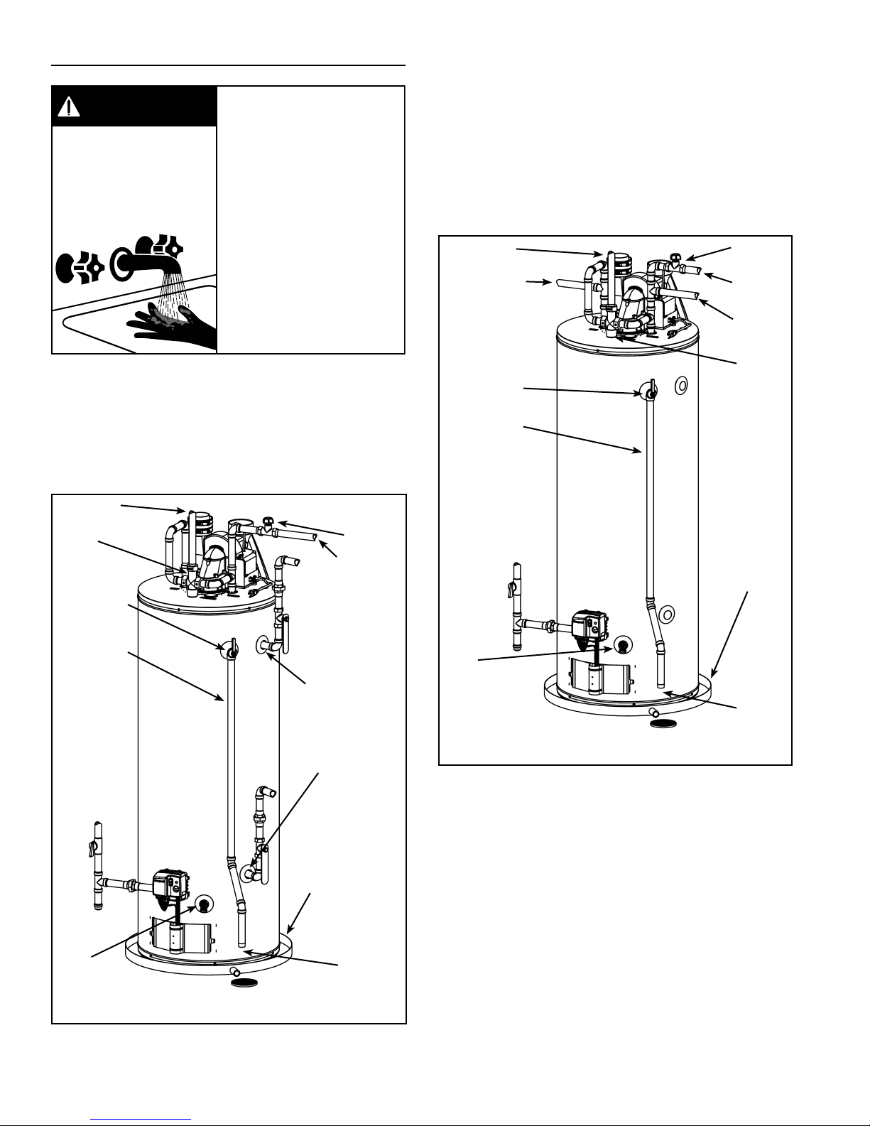
WATER PIPING - MIXING VALVE USAGE
Mixing Valves
Water temperature over
DANGER
125°F (52°C) can cause
severe burns instantly
resulting in severe injury or
death.
Children, the elderly and the
disabled and are at highest
risk of scald injury.
This appliance has been design certifi ed as complying
with CSA Standard for water heaters and are considered
suitable for combination Water (Potable) Heating and
Space Heating but not space heating only applications.
The water supply pressure should not exceed 80 psi. If this
occurs, a pressure reducing valve with a bypass should be
installed in the cold water inlet line. This should be placed
on the supply to the entire house in order to maintain equal
hot and cold water pressures.
Feel water before bathing or
showering.
HOT
HOT
Temperature limiting devices
such as mixing must be
installed when required by
BURN
codes and to ensure safe
temperatures at fixtures.
Water heated to a temperature which satisfi es space
heating, clothes washing, dish washing, and other
sanitizing needs can scald and cause permanent injury
upon contact. Short repeated heating cycles caused by
small hot-water uses can cause a temperature increase
of the hot water by 11C° (20F°) higher than the heater’s
temperature settings.
TEMPERED
POTABLE WATER
MIXING
VALV E
TEMPERATUREPRESSURE
RELIEF VALVE
DISCHARGE
PIPE (DO NOT
CAP OR PLUG)
* NOTE: THE
T&P VALVE
DISCHARGE
PIPE MUST
BE PIPED
DIRECTLY TO
THE DRAIN
OR EXTERNAL
TO THE
BUILDING
SUGGESTED PIPING ARRANGEMENT
FOR TOP CONNECTIONS
SHUT-OFF
VALV E
COLD-WATER
INLET
CERTAIN MODELS
ARE EQUIPPED WITH
SIDE PLUMBING
CONNECTIONS FOR
SPACE HEATING.
THE HOT AND
COLD FITTING
ASSEMBLIES (PART
#9001262005) CAN
BE ORDERED
THROUGH THE
MANUFACTURER
METAL DRAIN
PAN 45mm (1.75”)
MAX. DEPTH. AT
LEAST 50mm (2”)
GREATER THAN THE
DIAMETER OF THE
WATER HEATER.
TEMPERED
POTABLE WATER
NON-TEMPERED
WATER SUPPLY
SUGGESTED PIPING
ARRANGEMENT FOR
TOP CONNECTIONS
TEMPERATUREPRESSURE
RELIEF VALVE
DISCHARGE
PIPE (DO NOT
CAP OR PLUG)
* NOTE: THE
T&P VALVE
DISCHARGE PIPE
MUST BE PIPED
DIRECTLY TO
THE DRAIN OR
EXTERNAL TO
THE BUILDING
DRAIN
VALV E
SHUT-OFF
VALV E
COLD-WATER
INLET
NON-TEMPERED
WATER RETURN
MIXING VALVE
METAL DRAIN
PAN 45mm
(1.75”) MAX.
DEPTH. AT
LEAST 50mm
(2”) GREATER
THAN THE
DIAMETER OF
THE WATER
HEATER.
305mm
(12”) MAX.
AIR GAP*
Figure 8
DRAIN
VALV E
Figure 7
328126-000 www. johnwoodwaterheaters .com 9
305mm (12”)
MAX. AIR
GAP*
Some people are more likely to be permanently injured
by hot water than others. These include the elderly,
children, the infi rm and the physically/mentally disabled.
Table 1 (published by U.S. Government Memorandum,
1978) shows the approximate time-to-burn relationship
for normal adult skin. If anyone using hot water provided
by the water heater being installed fi ts into one of these
groups or if there is a local code or state law requiring a
certain water temperature at the point of use, then special
precautions must be taken.
Water
Temperature
°C (°F)
Time for 1st
Degree Burns
(Less Severe Burns)
44 (110) (normal shower temp.)
47 (116) (pain threshold)
47 (116) 35 minutes 45 minutes
50 (122) 1 minute 5 minutes
55 (131) 5 seconds 25 seconds
60 (140) 2 seconds 5 seconds
65 (149) 1 second 2 seconds
68 (154) instantaneous 1 seconds
(U.S. Government Memorandum, C.P.S.C., Peter L. Armstrong,
Sept. 15,1978)
Time for Permanent
Burns 2nd & 3rd
Degree (Most
Severe Burns)
Table 1
In addition to using lowest possible temperature setting
that satisfi es demand of application, a mixing valve should
be installed at water heater (see Figure 7 & Figure 8) or at
hot-water taps to further reduce system water temperature.
Mixing valves are available at plumbing supply stores.
Consult a Qualifi ed Installer or Service Agency. Follow
mixing valve manufacturer’s instructions for installation
of the valves. Before changing the factory setting on the
thermostat, read the “Operating The Temperature Control
System” section in this manual.
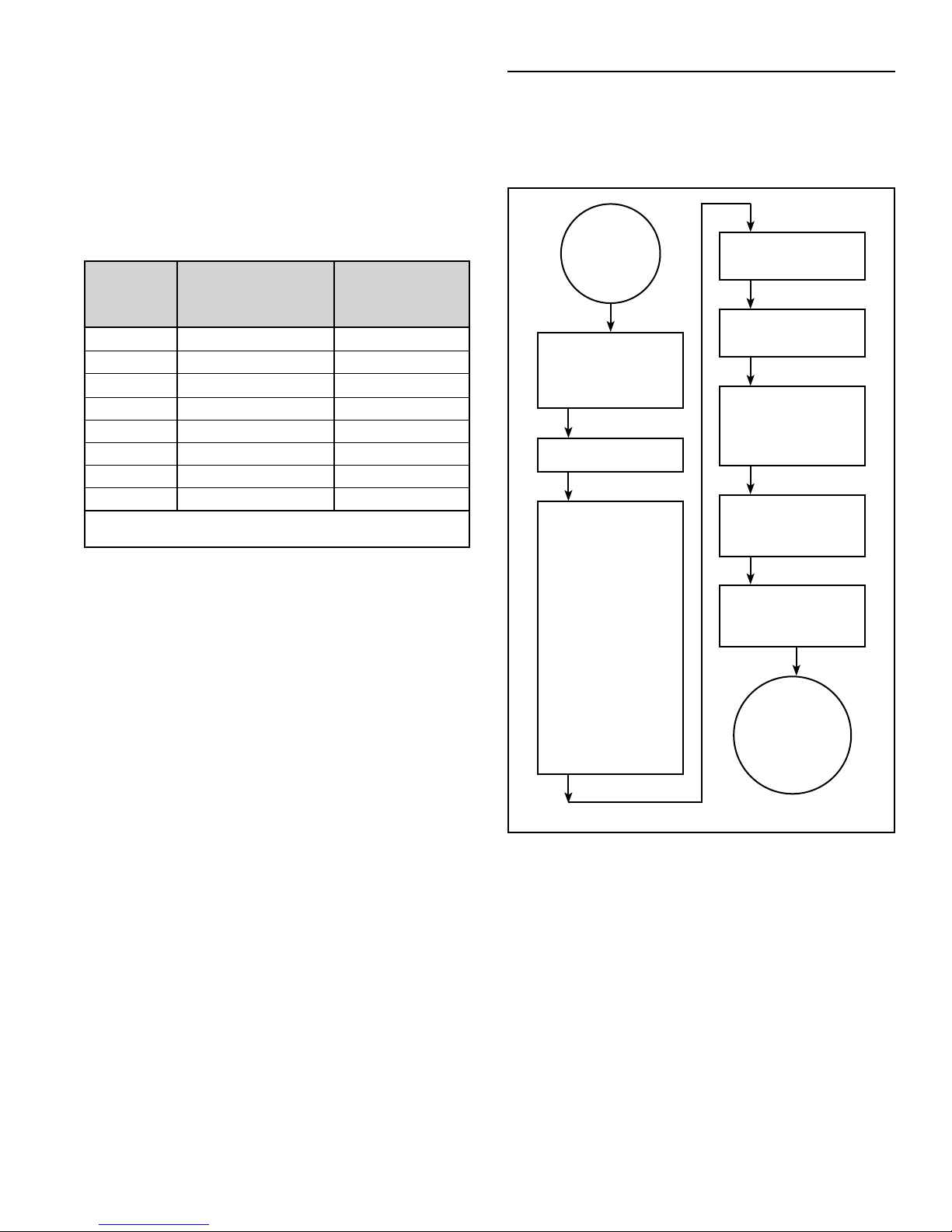
WATER HEATER OPERATION
Figure 9 shows the water heater’s sequence of operation
when a call for heat is initiated. The ignition control module
will attempt to light the burner three times. If the ignition
control does not detect ignition it will enter lockout mode
and fl ash the corresponding error code.
HEATER
THERMOSTAT
CALLS FOR
HEAT
HEATER CONTROL
CHECKS TO ENSURE
BLOWER EXHAUST
PRESSURE SWITCH IS
OPEN
BLOWER IS
ENERGIZED
CONTROL CHECKS
TO ENSURE:
EXHAUST PRESSURE
SWITCH CLOSES AND
INTAKE PRESSURE
SWITCH REMAINS
CLOSED INDICATING
BLOWER IS
OPERATING AND
THERE ARE NO
BLOCKAGES (INTAKE
OR EXHAUST)
TEMPERATURE
SWITCH REMAINS
CLOSED INDICATING
VENT TEMPARATURE IS
NOT ABOVE THE
ALLOWEBLE LIMIT
IGNITER IS ENERGIZED
AND GAS VALVE IS
OPENED
BURNER COMES ON
AND THE FLAME IS
SENSED BY CONTROL
BURNER CONTINUES
TILL THE WATER IN THE
TANK REACHES THER-
MOSTAT SETTING
GAS VALVE IS CLOSED
AND BURNER SHUTS
OFF
BLOWER CONTINUES
FOR A POST PURGE
TIME
HEATER
REMAINS ON
STANDBY UNTIL
NEXT CALL FOR
HEAT
10 www. johnwoodwaterheaters .com 328126-000
Figure 9
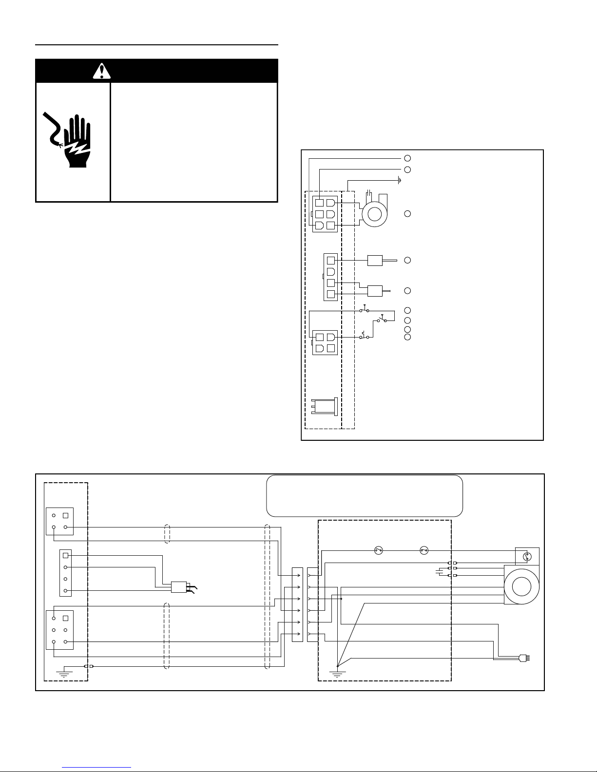
ELECTRICAL REQUIREMENTS & WIRING DIAGRAM
WARNING
Electric Shock Hazard
Disconnect power before
servicing.
Replace all parts and panels
before operating.
Failure to do so can result in
death or electrical shock.
Before plugging in the water heater, always make sure:
• The voltage and frequency correspond to that
specifi ed on the water heater wiring diagram.
• The electrical outlet has the proper overload fuse or
breaker protection.
1. The unit must be connected to a dedicated power
supply.
2. The unit must be connected to a 120VAC power
supply.
3. The water heater must be properly grounded.
4. This water heater is a polarity sensitive appliance and
will not operate if the power supply polarity is reversed.
Note: Always reference the wiring diagram for the correct
electrical connections.
CAUTION:
LABEL ALL WIRES PRIOR TO DISCONNECTION WHEN
SERVICING CONTROLS. WIRING ERRORS CAN
CAUSE IMPROPER AND DANGEROUS OPERATION.
VERIFY PROPER OPERATION AFTER SERVICING.
POWER VENT WIRING SCHEMATIC.
NOTE: REFER TO THE “INSTALLATION CHECKLIST”
BEFORE OPERATING THIS HEATER.
N
1
L1
1
EARTH GND
CAPACITOR
3
6
BLOWER
2
5
P1
4
1
4
3
P2
2
1
2
4
P3
1
3
3
FLAME SENSOR
6
5
HOT SURFACE IGNITER
4
PRESSURE SWITCH (CLOSED)
PRESSURE SWITCH (OPEN)
2
PRESSURE SWITCH (CLOSED)
4
HIGH LIMIT SWITCH (CLOSED)
4
After making all electrical connections, completely fi ll the
tank with water and check all connections for leaks. Open
the nearest hot-water faucet and let it run for 3 minutes to
purge the water lines of air and sediment and to ensure
complete fi lling of the tank. The electrical power may then
be turned on. Verify proper operation after servicing. See
also “Installation Checklist”.
IF WIRING HAS TO BE REPLACED IN THE FIELD, USE ONLY TYPE TEW 105°C WIRE.
3
1
4
2
1
2
3
4
1
4
2
5
3
6
YELLOW
YELLOW
WHITE
WHITE
WHITE
BLUE
BLUE
BLACK
GREEN
IGNITER - FLAME ROD
ASSEMBLY
P4
ELECTRICAL RATING 120V, 5A, 60 HZ.
PRESSURE
SWITCH
YELLOW
BLUE
JP
1
1
2
2
3
3
4
4
5
5
6
6
(NO)
BLACK SMOOTH - LINE
BLACK RIBBED - NEUTRAL
BLACK MIDDLE - GND
Circled numbers indicate
sequence of operation.
Figure 11
PRESSURE
SWITCH
(NC)
CAPACITOR
BLACK
BLACK
BLACK
WHITE
GREEN
120Vac/60Hz Wall Plug
HIGH LIMIT
BLOWER
SWITCH
HONEYWELL GAS VALVE
Figure 10
328126-000 www. johnwoodwaterheaters .com 11
JUNCTION BOX

SAFETY LOCKOUTS
This water heater has several lockout features designed
to prevent the heater from operating in unsafe conditions.
HIGH LIMIT CONTROLS (ENERGY CUT OFF)
Thermostat/Water Temperature
This feature is a part of the gas control valve/thermostat
(see Figure 1, item 10) and limits the maximum water
temperature. In the event of the water overheating, this
safety feature shuts off the fuel supply to the burner.
Blower High Limit Switch
This device is located on the blower (see Figure 5, item
45) and limits the maximum temperature of the blower.
If the blower temperature rises above the temperature
setting, the switch opens causing the heater to shut down.
The switch will auto reset once the temperature drops
suffi ciently.
BLOWER AIR PRESSURE SWITCHES
The blower/heater is equiped with two air pressure
switches located in the junction box (see Figure 5, item
46 and item 49). These devices are connected in series
and monitor the air pressure produced by the blower. In
the event that the exhaust venting becomes blocked or
suffi ciently restricted, the normally open (NO) air pressure
switch will shut down the heater. In the event that the
intake pipe becomes suffi ciently blocked or restricted, the
normally closed (NC) air pressure switch will shut down
the heater.
12 www. johnwoodwaterheaters .com 328126-000
LOCATING THE NEW WATER HEATER
FACTS TO CONSIDER ABOUT THE LOCATION
Carefully choose an indoor location for the new water
heater because the placement is a very important
consideration for the safety of the occupants in the building
and for the most economical use of the appliance. This
water heater is not for use in manufactured (mobile) homes
or outdoor installation.
Whether replacing an old water heater or putting the water
heater in a new location, the following critical points must
be observed:
1. Select a location indoors as close as practical to
the vent termination or location to which the water
heater vent piping is going to be connected, and as
centralized with the water piping system as possible.
2. Selected location must provide adequate clearances
for servicing and proper operation of the water heater.
3. Avoid locations that could cause the water heater to
freeze from outside air.
4. Selected location must provide access to a properly
grounded electrical branch circuit. A dedicated circuit
is preferred. Do not use a GFI outlet.
5. Avoid locations that expose the water heater to direct
sunlight.
6. Keep combustibles such as boxes, magazines,
clothes, etc., away from the water heater area.
Important: Do not use an extension cord to connect the
water heater to an electrical outlet.
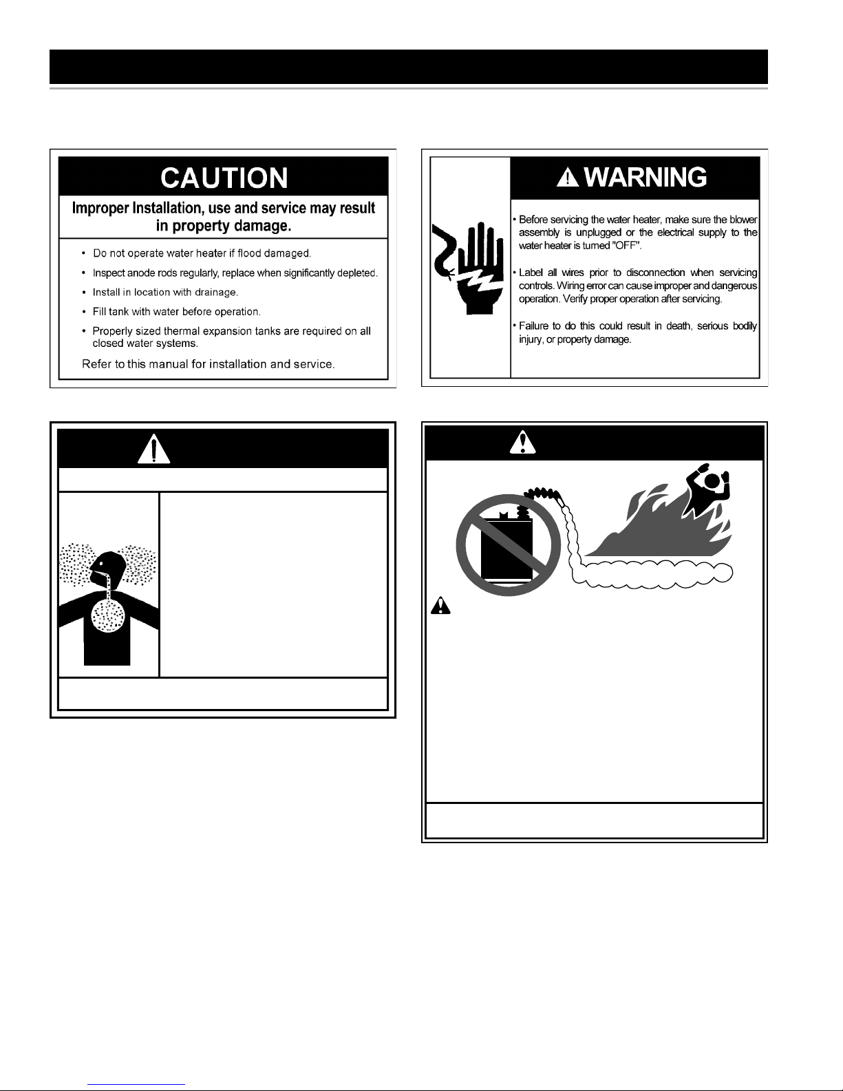
CAUTION
• Sensors mounted in the metal drain pan that trigger an
alarm or turn off the incoming water to the water heater
when leakage is detected.
• Sensors mounted in the metal drain pan that turn off
the water supply to the entire building when water is
detected in the metal drain pan.
• Water supply shut-off devices that activate based on
the water pressure differential between the cold-water
and hot-water pipes connected to the water heater.
• Devices that will turn off the gas supply to a gas water
heater while at the same time shutting off its water
supply.
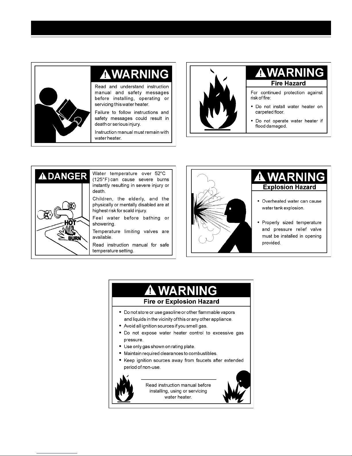
WARNING
Fire or Explosion Hazard
• Do not store or use gasoline or other flammable vapours
and liquids in the vicinity of this or any other appliance.
• Avoid all ignition sources if you smell gas.
• Do not expose water heater control to excessive gas
pressure.
• Use only gas shown on rating plate.
• Maintain required clearances to combustibles.
• Keep ignition sources away from faucets after extended
period of non-use.
Read instruction manual before
installing, using or servicing
water heater.
Property Damage Hazard
• All water heaters eventually leak.
• Do not install without adequate drainage.
Installation of the water heater must be accomplished
in such a manner that if the tank or any connections
should leak, the fl ow of water will not cause damage to
the structure. For this reason it is not advisable to install
the water heater in an attic or upper fl oor. In all cases, a
metal drain pan should be installed under the water heater.
Metal drain pans are available at your local hardware store.
Such a metal drain pan must have a clearance of at least
25mm (1”) greater than any point on the water heater’s
outer jacket and must be piped to an adequate drain. The
pan must have a maximum depth of 45mm (1.75”).
Water heater life depends upon water quality, water
pressure and the environment in which the water heater
is installed. Water heaters are sometimes installed in
locations where leakage may result in property damage,
even with the use of a metal drain pan piped to a drain.
However, unanticipated damage can be reduced or
prevented by a leak detector or water shut-off device used
in conjunction with a piped metal drain pan. These devices
are available from some plumbing supply wholesalers and
retailers, and detect and react to leakage in various ways:
WARNING
FLAMMABLES
FIRE AND EXPLOSION HAZARD
Can result in serious injury or death
Do not store or use gasoline or other flammable vapors and
liquids in the vicinity of this or any other appliance. Storage or
use of gasoline or other flammable vapors or liquids in the
vicinity of this or any other appliance can result in serious injury
or death.
Flammable Vapors
WARNING
Fire Hazard
For continued protection against
risk of fire:
• Do not install water heater on
carpeted floor.
• Do not operate water heater if
flood damaged.
328126-000 www. johnwoodwaterheaters .com 13
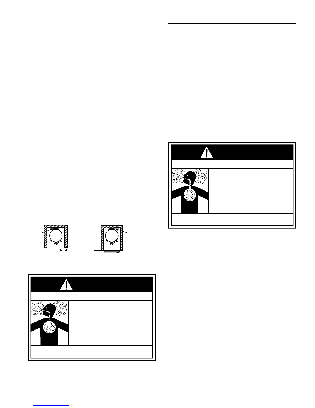
Clearances To Combustibles
Minimum clearances between water heater and
combustibles are 0mm (0”) at the sides and rear, 140mm
(5.5”) from the front and 305mm (12”) from top (standard
clearance.) If clearances stated on the heater differ from
standard clearances, install water heater according to
clearances stated on the heater (see Figure 12).
Floors With Carpeting
This water heater must not be installed directly on
carpeting. Carpeting must be protected by a metal or wood
panel beneath the appliance extending beyond the full
width and depth of the appliance by at least 76mm (3”) in
every direction, or if the appliance is installed in an alcove
or closet, the entire fl oor must be covered by the panel.
Failure to heed this warning may result in a fi re hazard.
Clearances For Servicing
When installing the heater, consideration must be given to
proper location. Location selected should be as close to
the wall as practicable and as centralized with the water
piping system as possible.
Servicing this appliance, such as changing the anodes,
etc. requires clearances for accesability and replacement
of parts. The anode could be as long as 0.89m (35”).
Refer to the current edition of the “Natural Gas and
Propane Installation Code” B149.1 for detailed
requirements.
HIGH AMBIENT TEMPERATURE INSTALLATIONS
As the room temperature rises, the water heater venting
is exposed to high temperatures from the inside and the
outside. In these situations, attention to the choice of
venting material is necessary. Establishing the ambient
temperatures where the heater and the venting are
installed is very important. Areas that can experience
high ambient environments include closets, alcoves,
areas under staircases, attics (especially in metal roofed
buildings), areas with restricted air movement, rooms with
large solar gains, metal sheds, industrial or commercial
enterprises and venting systems exposed to direct
sunlight. Water heater installations in ambient conditions
hotter than 43°C (110°F) require the installation of a high
ambient limit switch (kit number 9009024015) and use of
CPVC or polypropylene venting material. Failure to install
the proper vent material will result in a non-compliant
installation and can result in deformation/breakage
of the pipe.
WARNING
Breathing Hazard - Carbon Monoxide Gas
• Flue gases may escape if
vent pipe is deformed,
broken, or not properly
connected.
0mm
(0”) MIN.
TOP VIEW
OF CLOSET
WITHOUT DOOR
0mm
(0”) MIN.
(5.5”) MIN.
140mm
TOP VIEW OF
CLOSET WITH
Figure 12
WARNING
Breathing Hazard - Carbon Monoxide Gas
• Install water heater in accordance with the
instruction manual and B149.1.
• To avoid injury, combustion and ventilation air
must be taken from outdoors.
• Do not place chemical vapour emitting products
near water heater.
Breathing carbon monoxide can cause brain damage or death.
Always read and understand instruction manual.
14 www. johnwoodwaterheaters .com 328126-000
DOOR
0mm
(0”) MIN.
Breathing carbon monoxide can cause brain damage or death.
Always read and understand instruction manual.
Important Notes and Warnings
• This heater is certifi ed to be installed using Schedule 40
PVC or CPVC or polypropylene plastic vent material. All
jurisdictions in Canada require that the material used to
exhaust combustion products is approved to ULC S636.
Only use approved material. All venting material and
components must be joined with the approved primer/
cleaner and solvent cement.
• Do not common vent this heater with any other
appliance.
• During operation the plastic piping will expand as it
heats up and contract as it cools down. This is normal
for this type of venting. Rigidly fastening the vent piping
can cause undue stress that may result in the cracking
or fracturing the vent piping material. A fracture of the
venting pipe may pose a serious safety hazard. To
prevent stressing of the vent system, all hangers and
supports must allow the vent piping freedom to move.
• Use long sweep elbows wherever possible. Closely
coupled elbows and short radius elbows can reduce
the venting capacity.
• All power vented water heaters generate a certain
amount of operational noise. In order to minimize
noise transmission to the support structure, it is
recommended to use isolation pads between the pipe
hangers and the vent pipe.

• Most power vent installations develop some
condensation in the vent piping. When using long runs
of venting or when the venting passes through cold or
unheated areas, considerable amounts of condensate
from the fl ue gases can develop. Provision must be
made for the condensate to drain freely from the
system or to be collected in a condensate trap(s) that
can be drained. Damage or fracture of the vent piping
may occur if the condensate is allowed to collect and
freeze. Pooling of condensate can restrict airfl ow and
can cause nuisance failures of the system.
AIR REQUIREMENTS
For safe operation an adequate supply of fresh,
uncontaminated air for combustion, dilution and ventilation
must be provided.
Note: Contaminated or dusty air may cause build-up on
the blower wheel resulting in nuisance shut downs.
328126-000 www. johnwoodwaterheaters .com 15
INSTALLING THE NEW WATER HEATER
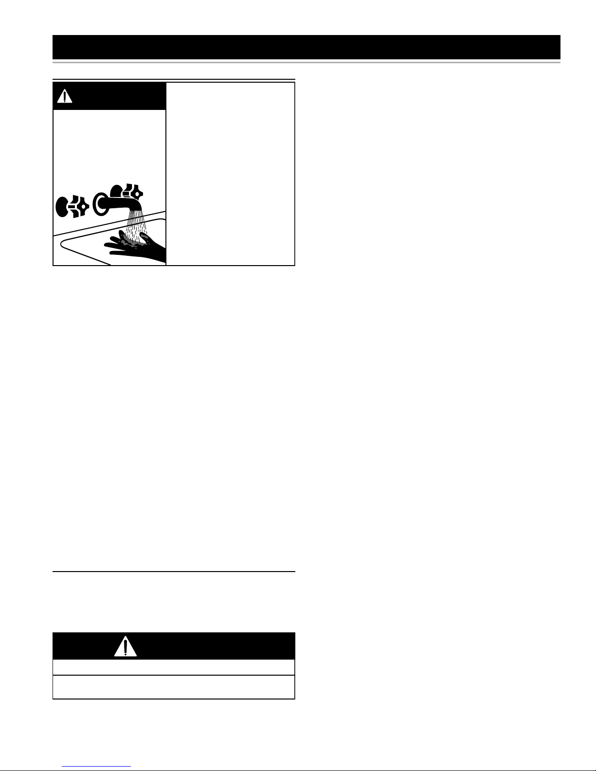
WATER PIPING
Water temperature over
DANGER
HOT
HOT
BURN
The water supply pressure should not exceed 80 psi. If this
occurs, a pressure reducing valve with a bypass should be
installed in the cold water inlet line. This should be placed
on the supply to the entire house in order to maintain equal
hot and cold water pressures.
HOT WATER CAN SCALD:
Water heaters are intended to produce hot water.
Water heated to a temperature which will satisfy space
heating, clothes washing, dish washing, cleaning and
other sanitizing needs can scald and permanently injure
you upon contact. Some people are more likely to be
permanently injured by hot water than others. These
include the elderly, children, the infi rm, or physically/
mentally handicapped. If anyone using hot water fi ts into
one of these groups you must take special precautions.
The National Plumbing Code requires certain fi xtures
to not exceed 49°C (120°F). In addition to using lowest
possible temperature setting that satisfi es your hot water
needs, a means such as a mixing valve, should be used
at hot-water taps used by these people or at the water
heater (see Figure 7 & Figure 8). Valves for reducing point
of use temperature by mixing cold and hot water are also
available.
SPACE HEATING AND POTABLE WATER SYSTEMS
This appliance has been design certifi ed as complying
with CSA Standard for water heaters and is suitable for
combination water (potable) heating and space heating
but not space heating only applications.
125°F (52°C) can cause
severe burns instantly
resulting in severe injury or
death.
Children, the elderly and the
disabled and are at highest
risk of scald injury.
Feel water before bathing or
showering.
Temperature limiting devices
such as mixing must be
installed when required by
codes and to ensure safe
temperatures at fixtures.
WARNING
Toxic Chemical Hazard
• Do not connect to non-potable water system.
Consult a Qualifi ed Installer or Service Agency. Follow
manufacturer’s instructions for installation of valves.
Before changing the factory setting on thermostat, read
“Operating The Temperature Control System” section in
this manual.
• This water heater should not be connected to any
heating systems or components previously used with
a non-potable water heating appliance.
• All piping components connected to this unit for space
heating applications should be suitable for use with
potable water.
• Toxic chemicals, such as those used for boiler treatment
shall not be introduced into the potable water used for
space heating.
• When the system requires water for space heating at
temperatures higher than required for domestic water
purposes, a mixing valve must be installed. Please
refer to Figure 7 & Figure 8 for suggested piping
arrangement.
Note: Water piping and vent piping occupy the space
above the water heater. Plan the water piping to ensure
it does not cause interference with the vent piping (see
“Planning the Vent System”).
If this water heater is to be used to supply both space
heating and potable water, the instructions listed below
must be followed:
• Be sure to follow the manual(s) shipped with the air
handler or other type heating system.
• This water heater is not to be used as a replacement
for an existing boiler installation.
• Do not use with piping that has been treated with
chromates, boiler seal or other chemicals and do not
add any chemicals to the water heater piping.
• If the space heating system requires water temperatures
in excess of 49°C (120°F), steps must be taken to limit
temperatures at fi xtures in the potable hot-water supply
for safety and regulatory requirements.
• Pumps, valves, piping and fi ttings must be compatible
with potable water.
• A properly installed fl ow control valve is required to
prevent thermosiphoning. Thermosiphoning is the
result of a continuous fl ow of water through the air
handler circuit during the off cycle. Weeping (blow off)
of the temperature-pressure relief valve (T&P) or higher
than normal water temperatures are the fi rst signs of
thermosiphoning.
• The hot-water line from the water heater should be
vertical past any mixing valve or supply line to the
heating system to remove air bubbles from the system.
• Do not connect the water heater to any system or
components previously used with non-potable water
heating appliances when used to supply potable water.
16 www. johnwoodwaterheaters .com 328126-000
COMBO HEATING
This section serves as a guide for the installation and use
of “Combo” heating systems utilizing a domestic water
heater that has been specifi cally approved for such use.
It is written for those knowledgeable in the required trades
and professionals involved in the design and installation
of Combo Heating Systems.
It is the responsibility of the installer/designer to follow all
applicable codes to ensure the effectiveness and safety
of the installation.
System Requirements
The following requirements must be met for the installation
of Combo Heating Systems:
1. All components used for the distribution of water in
the heating loop must be suitable for potable water.
These include all piping, fi ttings, solder and fl uxes,
pumps for circulation of water, valves, etc.
2. The water heater must not be connected to a hydronic
heating system that has been used previously.
3. No boiler treatment chemicals of any kind shall be
introduced into the system.
4. The Combo System components must be selected
and sized to meet and maintain the total calculated
demands for both domestic service hot water
and space heating requirement. The sizing and
installation must be performed in accordance with
good engineering practice such as “ASHRAE
Handbooks”, HRAI’s Unifi ed Combo Guidelines,
“Hydronics Institute Manuals”, ANSI Z223.1, CSA
F280, National/Provincial Building Codes, ANSI
and/or codes having jurisdiction.
5. The air handler (fan coil) and/or the circulating pump
in a baseboard hydronic loop will require a dedicated
120V circuit. This must be provided and identifi ed for
this purpose.
6. All piping between the water heater and the air handler
or hydronic baseboard loop must be adequately
insulated to reduce heat loss.
7. If the local jurisdiction requires a back-fl ow preventer
in the cold water line, an expansion tank of adequate
size must be installed.
8. “Combo” Heating Systems require higher water
temperatures than other applications. When the
system is used to supply water for Combo Heating
applications, a means, such as mixing valve, must be
installed to temper the water in order to reduce scald
hazard potential (see Figure 13 & Figure 14).
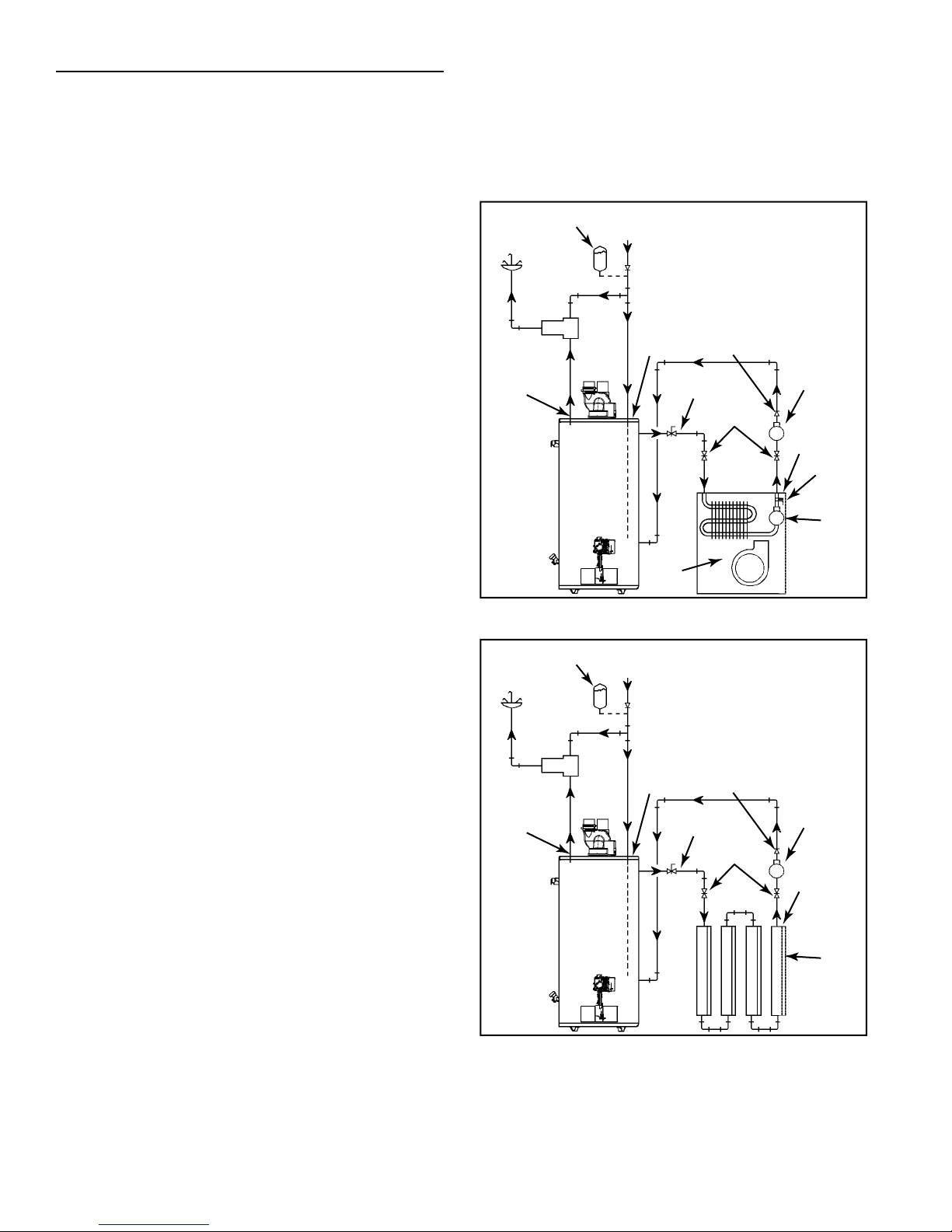
Installation
The heating mode may be one of the following options:
A. A fan coil/air handler (Figure 13).
B. A hydronic baseboard (fi nned tube) loop/In fl oor heating
(Figure 14).
The following is a list of requirements for the installation
of option A or B.
1. Install shut-off valves and unions so that the water
heater can be isolated from the heating module should
servicing of the water heater become necessary.
2. Install a drain valve at the lowest point of the heating
loop so that water can be drained from the heating
module without affecting the water heater.
3. If the air handler does not have a venting means at
the highest point of the piping arrangement, install
an air bleed at the highest point of the plumbing
arrangement.
HOT WATER
TO HOUSE
FIXTURE
MIXING
VALV E
HOT
OUTLET
EXPANSION TANK
(OPTIONAL)
C
M
H
WATER
HEATER
COLD SUPPLY
code requirements
CHECK VALVE (IF USED
REQUIRES EXPANSION TANK)
CHECK
COLD INLET
AIR
HANDLER
VALV E
FLOW
CONTROL
HOSE BIB
(OPTIONAL)
SUPPLY
(see also
Massachusetts
on pg 8)
EXTERNAL
CIRCULATOR
RETURN
DRAIN/
PURGE
VALV E
INTERNAL
CIRCULATOR
Figure 13
HOT WATER
TO HOUSE
FIXTURE
MIXING
VALV E
HOT
OUTLET
EXPANSION TANK
(OPTIONAL)
C
M
H
WATER
HEATER
COLD SUPPLY
code requirements
CHECK VALVE (IF USED
REQUIRES EXPANSION TANK)
CHECK
COLD INLET
VALV E
FLOW
CONTROL
HOSE BIB
(OPTIONAL)
SUPPLY
(see also
Massachusetts
on pg 8)
EXTERNAL
CIRCULATOR
RETURN
HYDRONIC
BASEBOARDS
(SERIES
CONNECTED
SHOWN)
Figure 14
328126-000 www. johnwoodwaterheaters .com 17
 Loading...