

POWER DIRECT VENT WATER HEATER
WARNING:
Improper installation, adjustment, alteration, service, or maintenance can cause
injury or property damage. Refer to this
manual. For assistance or additional information, consult a qualified installer, service agency, or the gas utility.
FOR YOUR SAFETY
• Do not store or use gasoline or other
flammable vapours and liquids in the
vicinity of this or any other appliance.
• Installation and service must be performed by a qualified installer, service
agency or the gas utility.
INSTALLATION AND
OPERATING INSTRUCTIONS
Read these instructions thoroughly before starting
WARNING:
If the information in these instructions is
not followed exactly, a fire or explosion
may result causing property damage, personal injury or death.
WHAT TO DO IF YOU SMELL GAS
• Do not try to light any appliance.
• Do not touch any electrical switch; do
not use any phone in your building.
• Immediately call your gas supplier from
a neighbor’s phone. Follow the gas
supplier’s instructions.
• If you cannot reach your gas supplier,
call the fire department.
PART No. 324330-001 (13-08)

This page intentionally left blank. May be used for notes or to record other installation information.
– 2 –

TABLE OF CONTENTS
I) INTRODUCTION . . . . . . . . . . . . . . . . . . . . . . . . . . .4
User Responsibilities 4
II) SAFETY . . . . . . . . . . . . . . . . . . . . . . . . . . . . . . . . . .5
For Installations in Canada: 5
For Installations in the United States: 5
Safety Warning (Flammable Vapours) 5
Safety Warning (Scalding) 5
Relief Valve Requirements (T&P) 6
III) INSTALLATION . . . . . . . . . . . . . . . . . . . . . . . . . . . .6
Unpacking the Water Heater 6
Location Requirements 6
Site Location 6
Clearances and Accessibility 7
In Earthquake Zones
Gas Supply 7
Gas Requirements
Gas Piping
Gas Pressure
Gas Pressure Testing
Venting 8
Vent Pipe Material
Vent Pipe Connection to Blower
Vent Pipe Installation
Vent Pipe Length
Vent Pipe Runs
Vent Pipe Termination
Vent Terminal Installations
Side Wall Vent Terminal Installation
Vertical Vent Terminal Installation
Concentric Vent Termination Kit Installation
Multiple Concentric Vent Installations
Water Supply 13
Piping Installation
Closed System/Thermal Expansion
Temperature and Pressure (T&P) Relief Valve 14
The Temperature and Pressure Relief Valve:
The Discharge Line:
Electrical Supply 14
Resettable Lockout 15
Installation Checklist 18
IV) LIGHTING & OPERATING INSTRUCTIONS . . . . .19
Lighting Instructions (Robertshaw) 19
First Lighting 20
Gas Control
Robertshaw 2000N WDER Operation
Temperature Adjustment
Lighting Instructions (White-Rodgers) 22
Gas Control/Thermostat
Putting the Heater into Service
Temperature Adjustment
Heater Shutdown
System Error Codes
TM
Intelli-Vent
System Error Codes
V) OPERATION . . . . . . . . . . . . . . . . . . . . . . . . . . . . . . . .26
Water Heater Operation 26
Burner Flames 26
Stacking 26
Emergency Shut Down 26
Operational Conditions 26
Condensation
Water Heater Sounds
Smoke/Odour
Anode Rod/Water Odour
VI) MAINTENANCE . . . . . . . . . . . . . . . . . . . . . . . . . . .28
Draining and Flushing 28
Routine Preventative Maintenance 28
Temperature and Pressure Relief Valve 28
Replacement Parts 28
VII) COMBO HEATING . . . . . . . . . . . . . . . . . . . . . . . . .29
System Requirements 29
Installation 30
VIII) TROUBLESHOOTING GUIDE . . . . . . . . . . . . . . . .31
Robertshaw 2000N WDER and
White-Rodgers Intelli-Vent
TM
31
IX) PARTS REFERENCE ILLUSTRATION . . . . . . . . .32
LIMITED WARRANTY . . . . . . . . . . . . . . . . . . . . . .33
RETAIN THESE INSTRUCTIONS IN A SAFE LOCATION FOR FUTURE REFERENCE
– 3 –
Your safety and the safety of others is very important.
We have provided many important safety messages in this manual and on your appliance.
Always read and obey all safety messages.
This is the safety alert symbol.
This symbol alerts you to potential hazards that can kill or hurt you and others.
All safety messages will follow the safety alert symbol and either the word
“DANGER” or “WARNING”.
DANGER
You can be killed or seriously injured if you don’t immediately follow
instructions.
WARNING
You can be killed or seriously injured if you don’t follow instructions.
All safety messages will tell you what the potential hazard is, tell you how to reduce the
chance of injury, and tell you what can happen if the instructions are not followed.
CAUTION
Hydrogen gas can be produced in a hot water system served by this heater that has not been used
for a long period of time (generally two (2) weeks or more). Hydrogen gas is extremely flammable
and can ignite when exposed to a spark or flame. To reduce the risk of injury under these conditions, it is recommended that the hot water faucet be opened for several minutes at the kitchen sink
before using any electrical appliance connected to the hot water system. Use caution in opening
faucets. If hydrogen is present, there will probably be an unusual sound such as air escaping through
the pipe as the water begins to flow. There should be no smoking or open flame near the faucet at
the time it is open.
Do not use this appliance if any part has been under water. Immediately call a qualified service technician. Water heaters subjected to flood conditions or anytime the gas controls, main burner or pilot
have been submerged in water require replacement of the entire water heater.
The California Safe Drinking Water and Toxic Enforcement Act requires the Governor of California to
publish a list of substances known to the State of California to cause cancer, birth defects, or other
reproductive harm, and requires businesses to warn of potential exposure to such substances.
WARNING: This product contains a chemical known to the State of California to cause cancer, birth
defects, or other reproductive harm.
This appliance can cause low-level exposure to some of the substances listed, including formaldehyde, carbon monoxide, and soot.
I) INTRODUCTION
Thank you for purchasing a Power Direct Vented Water
Heater. Properly installed and maintained, it will provide
years of trouble free service.
This gas-fired water heater has been developed to produce
potable hot water for normal residential demands and may
also be used in combination with space heating applications. Any deviation from these applications could affect your
warranty.
User Responsibilities
This manual has been prepared to acquaint you with the
installation, operation and maintenance of your gas water
heater and provide important safety information in these
areas. It is your responsibility to ensure that your water
heater is properly installed and cared for.
– 4 –
FAILURE TO FOLLOW THE INSTRUCTIONS IN THIS
MANUAL MAY RESULT IN SERIOUS BODILY INJURY
AND/OR PROPERTY DAMAGE. THOROUGHLY READ
AND UNDERSTAND ALL INSTRUCTIONS BEFORE YOU
ATTEMPT TO INSTALL, OPERATE OR MAINTAIN THIS
HEATER.
Installation and service requires trade knowledge in the
areas of plumbing, electricity, venting, air supply and gas
supply. If you lack these skills, or have difficulty understanding these instructions, you should not proceed. Enlist the
help of a qualified service technician to install this water
heater.
Examples of qualified service technicians include those
trained in the plumbing and heating industry, local gas utility
personnel, or an authorized service person.
Service to the Power Direct Vent System should only be
performed by a qualified service technician.
Safety Warning (Flammable Vapours)
The manufacturer and seller of this water heater will not
assume any liability for any property damage, personal
injury or death resulting from improper sizing, installation or
failure to comply with these instructions.
The warranty on this water heater is in effect only when the
water heater is installed and operated in accordance with
these instructions. A data plate identifying your water heater
can be found next to the gas control/thermostat. When referring to your water heater, always have the information listed
on the data plate readily available.
Protect your warranty: Regularly service your water heater
as directed in the "Maintenance" section of this manual.
Retain your original receipt as proof of purchase.
Do not discard this manual. You or future users of this
water heater will need it for reference.
II) SAFETY
This water heater is design-certified by CSA International as
a Category I, direct vented water heater which takes its combustion air from the outside of the structure and exhausts all
products of combustion to the outside of the structure.
In addition to the installation instructions found in this manual, the water heater must be installed in accordance with
all local and provincial or state codes or, in the absence of
such, with the latest editions of the following specifications.
For Installations in Canada:
“Natural Gas and Propane Installation Code” CSAB149.1 and
“Canadian Electrical Code (CAN/CSA C22.1), Part I”
available from:
Canadian Standards Association,
5060 Spectrum Way,
Mississauga, Ontario, Canada
L4W 5N6
For Installations in the United States:
“National Fuel Gas Code” ANSI Z223.1 (NFPA 54) and
“National Electrical Code” (NFPA 70)” available from:
American National Standards Institute,
25 West 43rd Street,
New York, NY 10036
Massachusetts code requires this water heater to be
installed in accordance with Massachusetts Plumbing and
Fuel Gas Code 248 CMR Section 2.00 and 5.00.
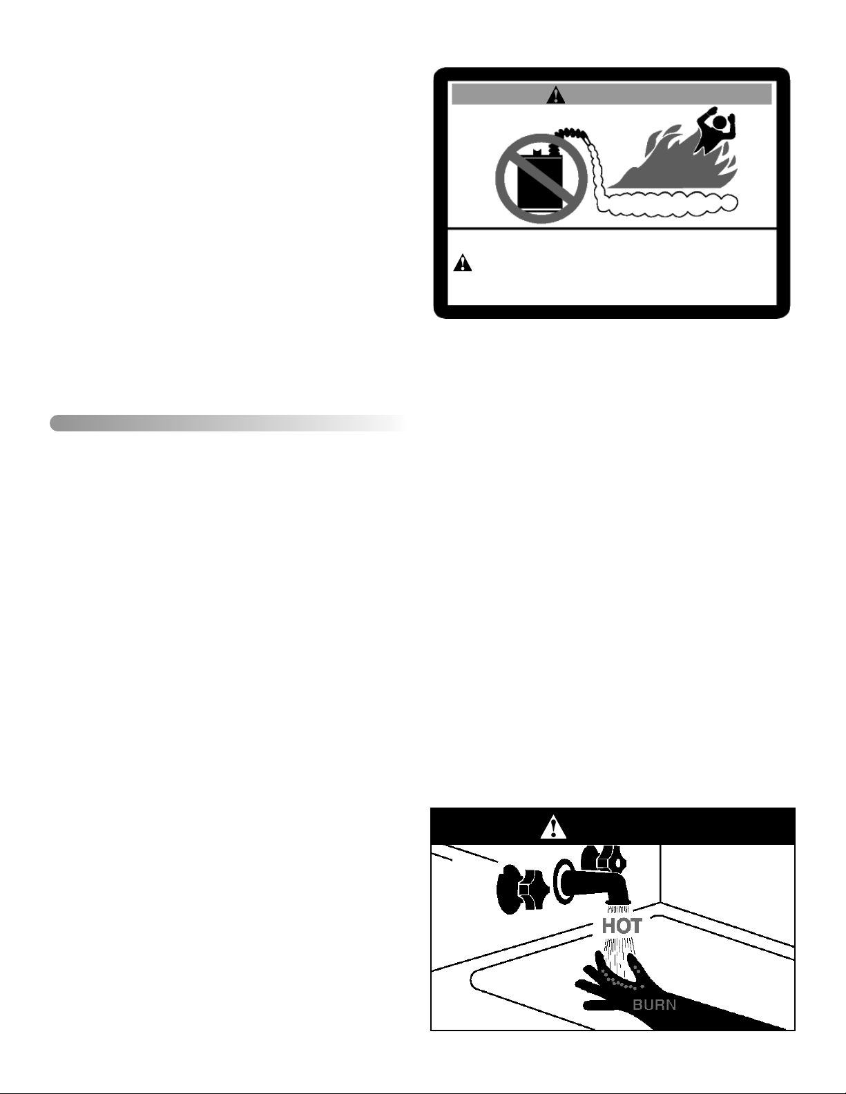
WARNING
FLAMMABLES
FIRE AND EXPLOSION HAZARD
Can result in serious injury or death
Do not store or use gasoline or other flammable vapours and liquids
in the vicinity of this or any other appliance. Storage of or use of gasoline
or other flammable vapours or liquids in the vicinity of this or any other
appliance can result in serious injury or death.
There is a risk of property damage, personal injury or death
from the by-products of combustion (e.g., flue gases), in
using fuel-burning appliances such as water heaters. Areas
that may not be suitable for water heater installation include
those where flammable liquids, gasoline, solvents, adhesives etc. are stored, or where engine-driven equipment or
vehicles are stored, operated or repaired. These, and similar
products, should not be stored or used near the water heater
or air intake. Due to the nature of air movement, flammable
vapours can be carried some distance from the point of storage. The gas-fired water heater igniter or burner flame can
ignite these vapours causing a flashback, fire or explosion,
which may result in severe property damage, serious personal injury or death. If flammable liquids or vapours have
spilled or leaked in the area of the water heater, leave the
area immediately and call the fire department from a neighbor’s home. Do not attempt to clean the spill until all ignition
sources have been extinguished.
Safety Warning (Scalding)
Hot water produced by this appliance can cause severe
burns due to scalding. The hazard is increased for young
children, the aged or the disabled when water temperatures
exceed 52°C (125°F). Use tempering valves, also known as
mixing valves, in the hot water system to reduce the risk of
scalding at point-of-use such as lavatories, sinks and bathing facilities. Such precautions must be followed when this
heater is operated in combination with dishwashing or space
heating applications.
Flammable Vapours
DANGER
Check your phone listings for the local authorities having
jurisdiction over your installation.
– 5 –
Relief Valve Requirements (T&P)
All water heaters must be fitted with a proper temperature
and pressure relief valve. These valves must be certified
as meeting the requirements of the “Standard For Relief
Valves For Hot Water Supply Systems, ANSI Z21.22/
CSA 4.4”.
MAKE SURE THE FLOW OF COMBUSTION AND
VENTILATION AIR IS NOT RESTRICTED.
If this water heater has been exposed to flooding, freezing,
fire or any unusual condition, do not put it into operation until
it has been inspected and approved by a qualified service
technician.
THESE CONDITIONS CAN RESULT IN UNSEEN
INTERNAL DAMAGE and are not subject to warranty cov-
erage.
III) INSTALLATION
Unpacking the Water Heater
WARNING
Excessive Weight Hazard
Use two or more people to move and install
water heater. Failure to do so can result in
back or other injury.
IMPORTANT:
This water heater must be installed strictly in accordance
with the instructions enclosed, and local electrical, fuel
and building codes. It is possible that connections to
the water heater, or the water heater itself, may develop
leaks. IT IS THEREFORE IMPERATIVE that the water
heater be installed so that any leakage of the tank or
related water piping is directed to an adequate drain in
such a manner that it cannot damage the building, furniture, floor covering, adjacent areas, lower floors of the
structure or other property subject to water damage. This
is particularly important if the water heater is installed in
a multi-story building, on finished flooring or carpeted
surfaces. THE MANUFACTURER WILL NOT ASSUME
ANY LIABILITY for damage caused by water leaking from
the water heater, pressure relief valve, or related fittings.
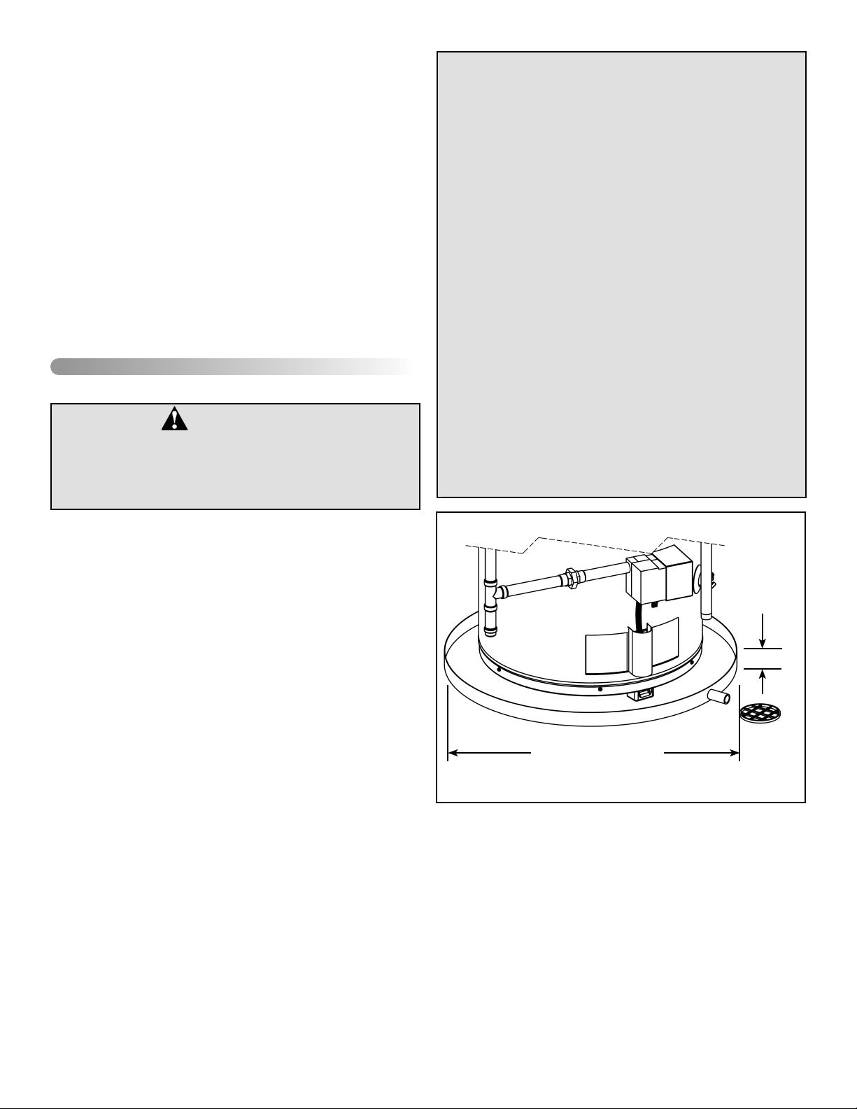
Select a location as centralized within the piping system
as possible. In any location selected, it is recommended
that a suitable drain pan be installed under the water
heater. This pan must limit the water level to a MAXIMUM
depth of 45mm (1 3/4 in.) and have a diameter that is a
minimum of 50mm (2 in.) greater than the diameter of the
water heater. Suitable piping shall connect the drain pan
to a properly operating floor drain. When used with a fuelfired heater, this drain pan must not restrict combustion
air flow.
Important: Do not remove any permanent instructions,
labels, or the data label from outside of the water heater or
on the inside of panels.
• Remove exterior packaging and place installation com-
ponents aside.
• Inspect all parts for damage prior to installation and start-
up.
• Completely read all instructions before attempting to
assemble and install this product.
If you observe damage to the water heater or any of its components, DO NOT ASSEMBLE OR INSTALL IT OR MAKE
ANY ATTEMPT TO FIX THE DAMAGED PART(S). Contact
the place of purchase for further instructions.
• After installation, dispose of packaging material in the
proper manner.
Location Requirements
Do not use or store flammable products such as gasoline,
solvents or adhesives in the same room or area near the
water heater. If such flammables must be used, all gas burning appliances in the vicinity must be shut off and their pilot
lights extinguished. Open the doors and windows for ventilation while flammable substances are in use.
Site Location
The water heater must be installed indoors and in a verti-
•
cal position on a level surface.
• Maximum ambient temperature 50°C (122°F).
Note: The water heater may be installed in a closet with
a door off a bedroom or bathroom providing the units are
installed and vented per the manufacturer’s instructions.
– 6 –
• Consider the air intake and exhaust vent system piping
• Locate the water heater near the existing gas piping. If
Note: This water heater must be installed in accordance
with all local and provincial or state codes or, in the absence
of such, the latest edition of “Natural Gas and Propane
Installation Code” CSA-B149.1 (Canada), or “National
Fuel Gas Code” ANSI Z223.1 (NFPA 54) (U.S.A.).
45mm MAX
(1 3/4 in.)
AT LEAST 50mm (2 in.)
GREATER THAN THE
WATER HEATER AND
BOTTOM AIR BOX.
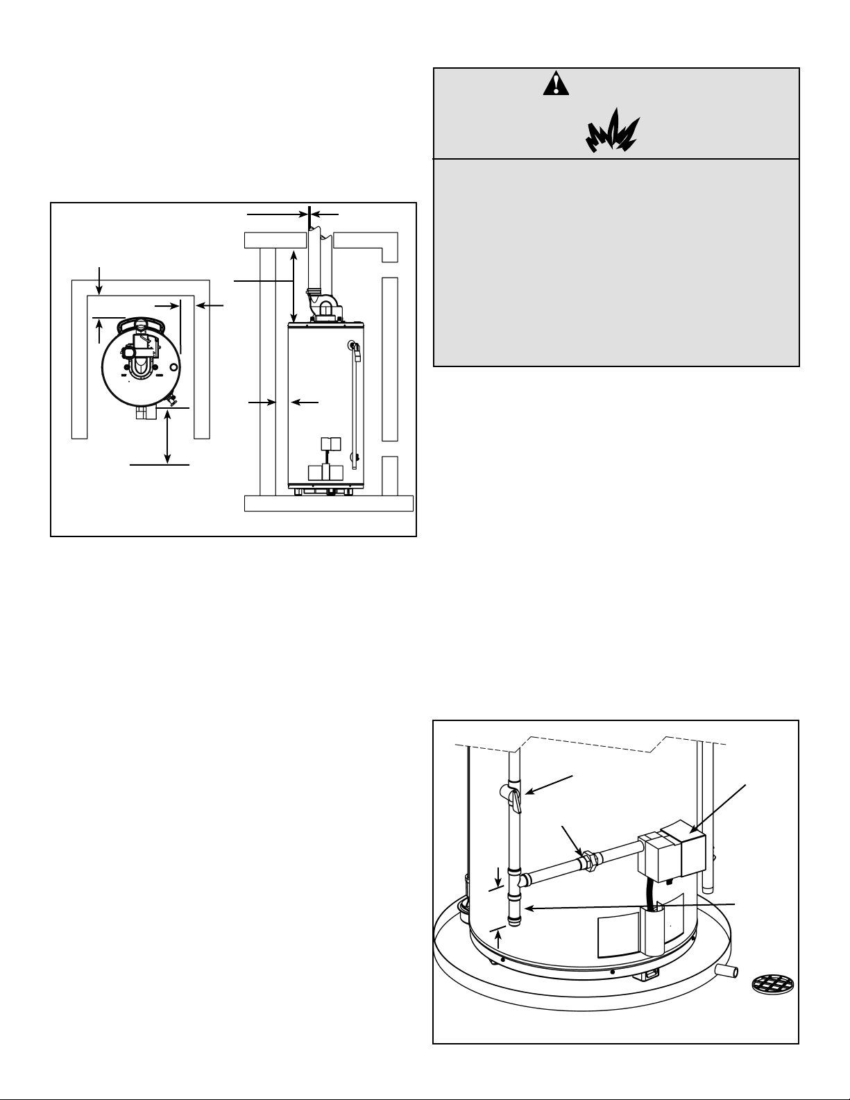
Figure 1. Drain Pan Installation
when selecting the water heater location. The venting
system must be able to run from the water heater to the
termination with a minimal length and number of elbows.
The venting system must comply with the requirements
set forth in the venting section of this manual.
installing a new gas line, locate the water heater to minimize the pipe length and elbows.
PIPE TO
ADEQUATE
DRAIN
• The water heater should be located in an area not sub-
ject to freezing temperatures. Water heaters located in
unconditioned spaces (i.e., attics, basements, etc.) may
require insulation of the water piping and drain piping
to protect against freezing. The drain and controls must
be easily accessible for operation and service. Maintain
proper clearances as specified on the data plate.
Clearances and Accessibility
VENT
BACK
TOP TO
CEILING
SIDES
Gas Supply
DANGER
Explosion Hazard
• Use a new CSA approved gas supply line.
• Install a gas supply shut-off valve.
• Do not connect a natural gas water heater
to a L.P. gas supply.
• Do not connect a L.P. gas water heater to
a natural gas supply
• Failure to follow these instructions can
result in death, an explosion or carbon
monoxide poisoning.
SIDES
FRONT 610mm
(24 in.) MIN.
FOR SERVICE
Figure 2. Minimum Clearance Locations
• The minimum clearances between the heater and com-
bustible materials are:
Top 406mm (16 in.)
Front 100mm (4 in.)
Rear and Sides 25mm (1 in.)
Vent Pipe through Wall 0mm (0 in.)
Note: These requirements are also listed on the data plate
located on the front of the water heater.
• The water heater is certified for installation on a combus-
tible floor.
Important: If installing over carpeting, the carpeting must
be protected by a metal or wood panel beneath the water
heater. The protective panel must extend beyond the full
width and depth of the water heater by at least 76mm (3 in.)
in any direction or if in an alcove or closet installation, the
entire floor must be covered by the panel.
Figure 2 may be used as a reference guide to locate the
specific clearance locations. A minimum of 610mm (24 in.)
of front clearance and 100mm (4 in.) on each side should be
provided for inspection and service.
In Earthquake Zones
Note: The water heater must be braced, anchored, or
strapped to avoid moving during an earthquake. Contact
local utilities for code requirements in your area.
Gas Requirements
Read the data plate to be sure the water heater is made
for the type of gas you will be using in your home. This
information will be found on the data plate located near the
gas control valve. If the information does not agree with the
type of gas available, do not install or light. Call your dealer.
Note: An odourant is added by the gas supplier to the gas
used by this water heater. This odourant may fade over an
extended period of time. Do not depend upon this odourant
as an indication of leaking gas.
Gas Piping
This gas piping must be installed in accordance with all local
and provincial or state codes or, in the absence of such, the
latest edition of “Natural Gas and Propane Installation
Code” CSA-B149.1 (Canada), or “National Fuel Gas
Code” ANSI Z223.1 (NFPA 54) (U.S.A.).
Note: When installing gas piping, apply sealing compounds
approved for use with natural and propane gas.
MANUAL
GAS
SHUT-OFF
GROUND-
JOINT UNION
76mm
(3 in.)
GAS
CONTROL/
THERMOSTAT
SEDIMENT
TRAP (DIRT
LEG)
– 7 –
Figure 3. Gas Piping
1. Install a readily accessible manual shut-off valve in the
gas supply line as recommended by the local utility. The
owner/operator must be shown the location of this valve
and be given instructions on how to use it to shut off the
gas to the heater.
2. Install a sediment trap (dirt leg) (if not already incorporated
as part of the water heater) as shown. The sediment trap
(dirt leg) must be no less than 76mm (3 in.) long for the
accumulation of dirt, foreign material, and water droplets.
3. Install a ground joint union between the gas control/
hermostat and the manual shut-off valve. This is to allow
easy removal of the gas control/thermostat.
4. Turn the gas supply on and check for leaks. Use a
chloride-free soap and water solution (bubbles forming
indicate a leak) or other approved method.
Gas Pressure
WARNING
Exposure to a higher gas supply pressure
may cause damage to the control, resulting
in explosion or fire. Consult your local gas
supplier and gas authorities. DO NOT PUT
INTO SERVICE IF OVER-PRESSURIZATION
HAS OCCURRED.
Important: The gas supply pressure must not exceed the
maximum supply pressure as stated on the water heater’s
data plate.
Gas Pressure Testing
Important: This water heater and its gas connection must
be leak tested before placing the appliance in operation.
• If the code requires the gas lines to be tested at a pres-
sure exceeding 14 in. w.c. (3.5 kPa), the water heater
and its manual shut-off valve must be disconnected from
the gas supply piping system and the line capped.
• If the gas lines are to be tested at a pressure less than
14 in. w.c. (3.5 kPa), the water heater must be isolated
from the gas supply piping system by closing its manual
shut-off valve.
U.L. recognized fuel gas and (CO) detectors are recommended in all applications and should be installed using
the manufacturer’s instructions and local codes, rules, or
regulations.
Note: Air may be present in the gas lines and could prevent
the burner from lighting on initial start-up. The gas lines
should be purged of air by a qualified service technician
after installation of the gas piping system.
Venting
This water heater has a direct vent system in which all air
for combustion is taken from the outside atmosphere and all
combustion products are discharged to the outdoors.
This water heater must be properly vented for removal of
exhaust gases to the outside atmosphere. Correct installation of the vent pipe system is mandatory for the safe and
efficient operation of this water heater and is an important
factor in the life of the unit.
A Vent Kit included with this water heater consists of:
1. Two (2) 45° Vent Termination Elbows,
2. Two (2) more restrictive Vent Termination Screens,
3. Two (2) less restrictive Vent Termination Screens,
4. Air intake adapter (3 in. to 2 in. ABS reducer),
5. Blower outlet adapter (rubber coupling and gear clamps).
Vent pipe must be installed in accordance with all local and
provincial or state codes or, in the absence of such, the
latest edition of “Natural Gas and Propane Installation
Code” CSA-B149.1 (Canada), or “National Fuel Gas
Code” ANSI Z223.1 (NFPA 54) (U.S.A.).
Important: Check to make sure the vent pipe is not blocked
in any way.
Note: Do not common vent this water heater with any other
appliance. Do not install in the same chase or chimney with
a metal or high-temperature plastic from another gas or fuel
burning appliance.
DANGER
Carbon Monoxide Warning
• Follow all vent system requirements by
the local authorities having jurisdiction
over your installation.
• Failure to do so can result in death, explosion or carbon monoxide poisoning.
Vent Pipe Material
The following plastic materials may be used for both the
combustion air intake and exhaust vent system subject to
local and provincial or state codes:
• This heater is certified to be installed using Schedule 40
PVC or CPVC or polypropylene plastic vent material for
the exhaust. In Canada, the exhaust vent material must
be approved to ULC S636. ULC S636 mandates that
components from different systems must not be mixed in
the same vent runs. The combustion air intake material
may be PVC, ABS, CPVC or polypropylene. Check local
codes to determine which materials are allowed in your
area and only use approved material. All venting material and components must be joined with the approved
primer/cleaner and solvent cement. Do not cement the
venting system to the heater.
Note: Use only solid (not foam core) piping. Plastic pipe
and fittings are available through most plumbing suppliers.
Always check the marking on the pipe to make sure you are
using the correct material.
– 8 –
Vent Pipe Connection to Blower
A rubber coupling and gear clamps are supplied (Vent Kit)
with the water heater to connect the exhaust vent system to
the blower.
Important: These connections must be properly sealed to
prevent the leakage of the products of combustion into the
living area.
Vent Pipe Installation
The following guidelines should be followed when installing
the air intake and exhaust vent system:
• Venting should be as direct as possible with a minimum
number of pipe fittings.
• Vent diameter must not be reduced unless specifically
noted in the installation instructions.
• Support all horizontal pipe runs every 1.2m (4 ft.) and all
vertical pipe runs every 1.5m (5 ft.) or according to local
codes.
• Vents run through unconditioned spaces where below
freezing temperatures are expected, are not recommended.
• Vents run through unconditioned spaces inside a building
may result in the condensation of flue gases during the
winter season. The rubber coupling joined to the blower
includes a nipple with a yellow cap. In installations such
as this connect a condensation trap to this nipple.
The combustion air intake and exhaust vent system and
termination may be installed in one of the following type
terminations:
1. Horizontal (2 Pipe) (air intake and exhaust vent)
2. Vertical (2 Pipe) (air intake and exhaust vent)
3. Concentric Vent Termination (using Concentric Vent Kit
side wall termination only).
All pipe, fittings, pipe cement, primers and procedures
must conform to American National Standard Institute and
American Society for Testing and Materials (ANSI/ASTM)
standards in the United States. This water heater has been
design certified by CSA International for use with the specified (CSA) listed plastic vent pipe.
CAUTION:
Use of Solvent Cement and Primer
• Use only in well-ventilated areas.
• Do not use near flame or open fire.
• Use only the Solvent Cement and Primer
appropriate for the venting material being
used.
• Solvent cements for plastic pipe are flammable liquids and must be kept away from
all sources of ignition.
Do not use solvent cement to connect the exhaust vent system to the blower. Use the rubber coupling and gear clamps
instead. This connection must be removable to service the
heater. All other joints in the air intake and exhaust vent
systems must be properly cemented. Use an appropriate
solvent cement to connect the 3 in. to 2 in adapter/reducer
to air intake on the water heater.
1. Cut the pipe end square and remove all ragged edges
and burrs. Make sure the inside of the pipe is clean and
free of cuttings and loose dirt. Chamfer the end and apply
primer to the fi tting and pipe.
2. Using a suitable grade of pipe cement, apply a moderate,
even coat inside the fi tting. Apply a liberal amount of
cement to the outside of the pipe to socket depth.
Note: It is important to select the proper pipe cement for the
type plastic pipe being used.
3. Assemble the parts quickly while the cement is still wet.
Twist the pipe 1/4 turn during insertion and hold for 30
seconds.
Vent Pipe Length
The maximum allowable pipe lengths for air intake and
exhaust are listed in Table 1. The specified maximum
lengths are for each of the intake and exhaust systems and
not for the combined lengths of both systems. In addition,
each system requires a 45° long sweep elbow termination
with a restrictive screen. Minimum pipe length is 900mm (3
ft.) with a minimum of one 90° elbow per side.
1. Determine termination type and pipe size.
2. Determine number of elbows in vent system. Do not
include termination elbow. Calculate the maximum
equivalent length of the exhaust and air intake system.
MODEL
NUMBER
4040SN-PDV
5040SN-PDV
5065SN-PDV 76mm (3 in.) 9.2m (30 ft.) 15.3m (50 ft.)
Notes:
3. Vent lengths shown do not include vent termination
elbow.
4. A horizontal vent must have a 45° vent termination
elbow to direct the vent pipe downward.
5. A vertical vent must have a 90° vent termination elbow
to direct the vent pipe horizontally followed by a 45°
elbow to direct the vent pipe downward.
6. If additional elbows are used in the vent system the
allowable vent lengths are reduced (see chart below).
7. Two 45° elbows are considered the equivalent of one
90° elbow.
Equivalent lengths of straight pipe for various elbows
using Schedule 40 PVC or CPVC or polypropylene.
SIZE TYPE
50mm (2 in.) 90° 2.44m (8 ft.) 1.52m (5 ft.)
76mm (3 in.) 90° 2.44m (8 ft.) 1.52m (5 ft.)
50mm (2 in.) 45° 1.22m (4 ft.) 0.76m (2.5 ft.)
76mm (3 in.) 45° 1.22m (4 ft.) 0.76m (2.5 ft.)
Table 1. Maximum Allowable Vent Lengths
VENT PIPE
DIAMETER
50mm (2 in.) 15.2m (50 ft.) 15.2m (50 ft.)
76mm (3 in.) 30.5m (100 ft.) 30.5m (100 ft.)
50mm (2 in.) 15.2m (50 ft.) 15.2m (50 ft.)
76mm (3 in.) 30.5m (100 ft.) 30.5m (100 ft.)
CONCENTRIC
VENT
LENGTH
SHORT
SWEEP/
RADIUS
2 PIPE VENT
LENGTH
LONG
SWEEP/
RADIUS
– 9 –
Vent Pipe Runs
WARNING
This unit includes an air intake terminal and
an exhaust vent terminal.
1. The exhaust vent system must not, under any circumstances, be run downhill then run uphill thus forming a
valley. It may leave a space to accumulate condensation
and block vent pipe.
2. Horizontal runs require a minimum 3mm (1/8 in.) rise
per 1.5m (5 ft) and a support every 1.2m (4 ft.). Ensure
there is enough height between heater and termination
to raise vent pipe runs the required distance.
3. Vertical runs require a support every 1.5m (5 ft.) that
must provide proper support to prevent stress on the
pipes.
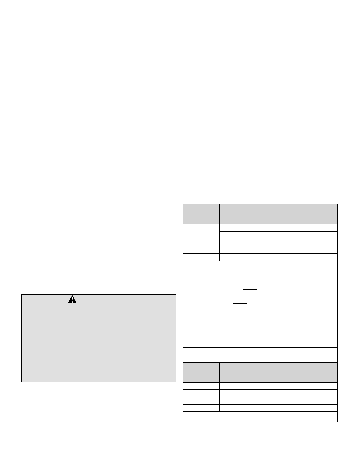
Vent Pipe Termination
This water heater includes one (1) pair of more restrictive
Vent Termination Screens and one (1) pair of less restrictive
Vent Termination Screens. For safety and optimum efficiency performance, ensure the correct Vent Termination Screen
is installed for the vent length in your installation.
Note: Before installing the Power Direct Vent Water Heater,
it is recommended that the location of the pipe terminations
(air intake and exhaust vent) be determined.
Use the more restrictive Vent Termination Screen shown
in Figure 5 when the equivalent vent length (see Table 1)
is between 2.1 and 7.6m (7 and 25 ft.). Install the Vent
Termination Screen in the Termination Elbow as shown, on
both the air intake pipe and the exhaust pipe.
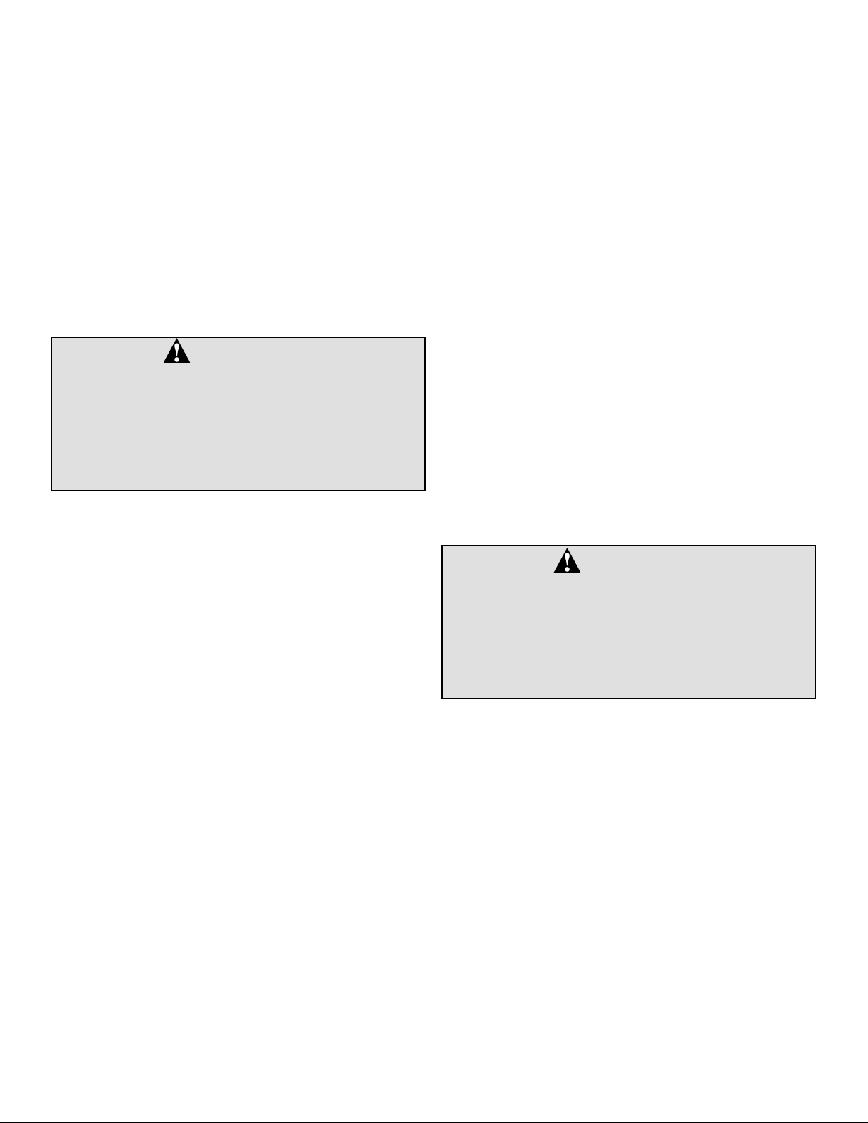
90° SHORT SWEEP ELBOW
(MORE RESTRICTIVE)
Figure 4. Correct Pipe Fittings
90° LONG SWEEP ELBOW
(LESS RESTRICTIVE)
Figure 5. Vent Termination Screen (more restrictive)
for equivalent vent lengths from 2.1 to 7.6m
(7 to 25 ft.).
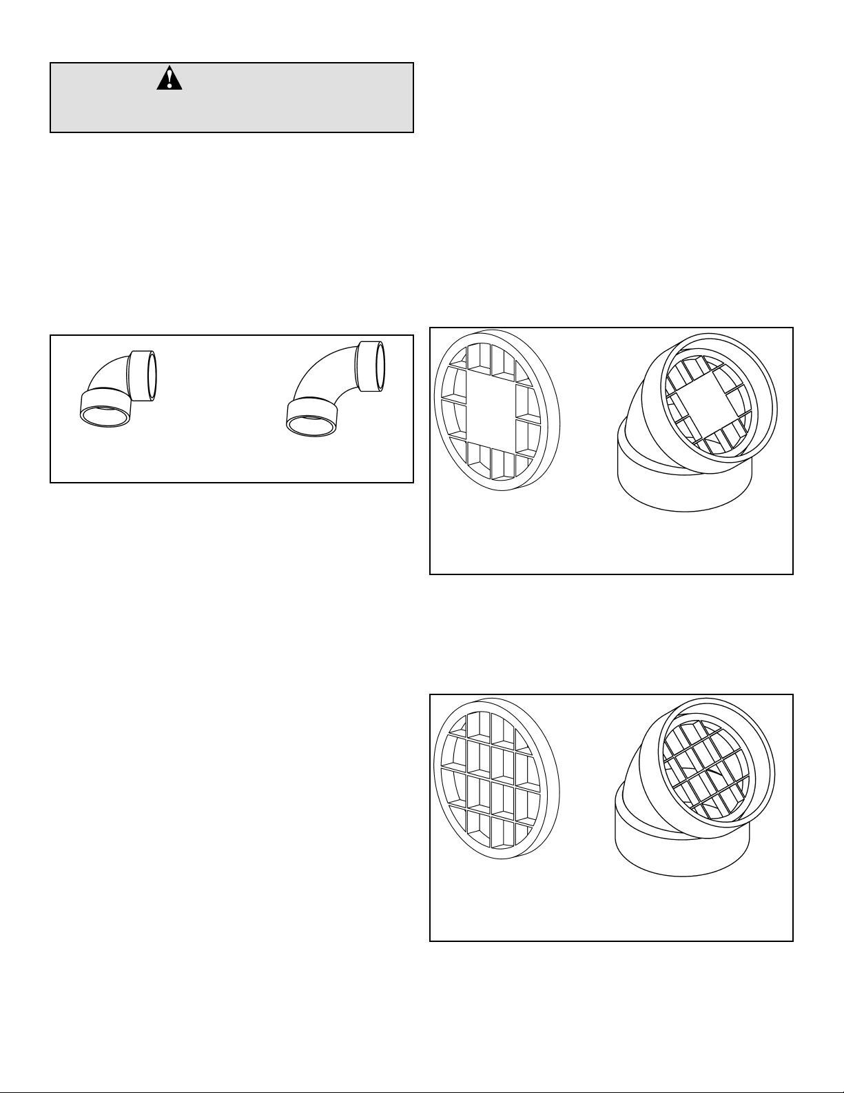
Use the less restrictive Vent Termination Screen shown
in Figure 6 when the equivalent vent length (see Table 1)
is between 7.6 and 15.2m (25 and 50 ft.). Install the Vent
Termination Screen in the Termination Elbow as shown, on
both the air intake pipe and the exhaust pipe.
– 10 –
Figure 6. Vent Termination Screen (less restrictive)
for equivalent vent lengths from 7.6 to
15.2m (25 to 50 ft.).
Vent Terminal Installations
Important: The vent system must terminate so that proper
clearances are maintained as cited in local codes or the
latest edition of “Natural Gas and Propane Installation
Code” CSA-B149.1 (Canada), or “National Fuel Gas
Code” ANSI Z223.1 (NFPA 54) (U.S.A.).
In addition, the manufacturer recommends the vent terminal
not to be installed closer than 150mm (6 in.) from an inside
or outside corner.
Plan the vent system layout so that proper clearances are
maintained from plumbing and wiring. Vent pipes serving
power vented appliances are classified by building codes as
“vent connectors”. Required clearances from combustible
materials must be provided in accordance with information
in this manual under “Location Of Heater” and with the latest
edition of “Natural Gas and Propane Installation Code”
CSA-B149.1 (Canada), or “National Fuel Gas Code” ANSI
Z223.1 (NFPA 54) (U.S.A.) and local codes.
Side Wall Vent Terminal Installation
Important: When terminating the vent on a side wall, the
following specifications pertaining to terminal location must
be followed (see Figure 7).
1. The air intake terminal and the exhaust vent terminal must
terminate on the same exterior wall.
2. The vertical centerline of the air intake terminal must be
located at a minimum of 203mm (8 in.) and not more than
610mm (24 in.) from the vertical centerline of the exhaust
vent terminal.
3. The horizontal centerline of the air intake terminal may not
be located more than 100mm (4 in.) below the horizontal
centerline of the exhaust vent terminal.
SIDE WALL
EXHAUST
VENT
TERMINAL
C
L
203mm (8 in.) MIN,
610mm (24 in.) MAX.
C
L
INTAKE
VENT
TERMINAL
C
L
C
L
100mm
(4 in.) MAX
Figure 7. Side Wall Vent Termination
Vertical Vent Terminal Installation
Important: When terminating the vents through a roof, the
following specifications pertaining to terminal location must
be followed (see Figure 8).
1. The air intake termination and the exhaust vent
termination shall extend above anticipated snow level or
at least 457mm (18 in.) above the roof.
2. Must provide proper support for all pipes protruding
through roof.
3. The vertical roof terminations should be sealed with a
plumbing roof boot or equivalent fl ashing.
4. The air intake termination and the exhaust vent termination
must penetrate the same side of roof.
5. The centerline of the air intake termination and the
centerline of the exhaust vent termination must not be
closer than 203mm (8 in.) and not farther away than
610mm (24 in.).
6. The air intake terminal and the exhaust vent terminal must
be oriented facing downward and the same direction.
– 11 –

203mm (8 in.)
“A” & “B”: ABOVE SNOW
ACCUMULATION LEVEL
OR 457mm (18 IN.) MIN.
ABOVE ROOF.
EXHAUST
VENT
TERMINAL
MIN.,610mm
(24 in.) MAX.
25mm
(1 in.)
25mm
(1 in.)
INTAKE
VENT
TERMINAL
B
A
Figure 8. Vertical Vent Installation
Concentric Vent Termination Kit Installation
A concentric Vent termination kit (see Table 2) may be used
for side wall termination installations.
VENT DIA. KIT P/N
50mm (2 in.) KGAVT0701 ULC 6911088
76mm (3 in.) KGAVT0801 ULC 6911089
Table 2. Concentric Vent Kits
Multiple Concentric Vent Installations
When two concentric vent kits are being installed, the vent
hood edges shall be either less than 50mm (2 in.) apart or
more than 915mm (36 in.) apart. Spacings between 50mm
(2 in.) and 915mm (36 in.) are not allowed due to the possibility of exhaust cross circulation (see Figure 10).
When more than 2 kits are installed only 2 of them shall be
less than 50mm (2 in.) apart. Never install 3 termination kits
together less than 50mm (2 in) apart (see Figure 11).
Figure 9 illustrates the Concentric Vent termination kit for
side wall installation. To prevent rain water from entering
the exhaust outlet, slope the vent kit at a downward pitch
of 6.5mm per 1.5m (1/4 in. per 5 ft.) away from the inside
wall. Ensure the combustion air intake location is above the
anticipated snow level.
ORIENTATION OF EXHAUST PIPING AND COMBUSTION AIR PIPING RELATIVE
TO EACH OTHER MAY BE VERTICAL (AS SHOWN) OR AT ANY OTHER ANGLE
TO SUIT THE INSTALLATION.
EXHAUST
COMBUSTION
AIR
ELBOW (FIELD
SUPPLIED)
STRAP (FIELD
SUPPLIED)
SLOPE 6.5mm OVER
1.5m (1/4 in. OVER 5 ft.)
Figure 9. Concentric Vent Termination (Side Wall Installation)
50mm (2 in.) MAX OR
915mm (36 in.) MIN
50mm
(2 in.) MAX
COMBUSTION AIR
25mm (1 in.) MAXIMUM
WALL
PIPE NIPPLE
(OPTIONAL)
90° ELBOW
(OPTIONAL)
SCREEN INSIDE
915mm
(36 in.) MIN
242mm (9.5 in.) MAX OR
1.105m (43.5 in.) MIN REF.
Figure 10. Dual Concentric Vent Terminations
– 12 –
242mm
(9.5 in.) REF.
1.105m
(43.5 in.) REF.
Figure 11. Multiple Concentric Vent Terminations

Water Supply
Piping Installation
Piping, fittings, and valves should be installed according to
the installation drawing (Figure 12). A pressure-reducing
valve and/or an expansion tank may be required for installations where the water pressure is high. The pressure-reducing valve should be located on the supply to the entire house
in order to maintain equal hot and cold water pressure.
Important: Heat cannot be applied to the water fittings on
the heater as they may contain nonmetallic parts. If solder
connections are used, solder the pipe to the adapter before
attaching the adapter to the hot and cold water fittings.
Important: Always use a proper grade of joint compound
and be certain that all fittings are drawn up tight.
1. Install the water piping and fi ttings as shown in Figure 12.
Connect the cold water supply to the fi tting (3/4” NPT)
marked “COLD” (or “C”). Connect the hot water supply
to the fi tting (3/4” NPT) marked “HOT” (or “H”).
Important: Some models may contain energy saving heat
traps to prevent the circulation of hot water within the pipes.
Do not remove the inserts within the heat traps.
2. The installation of unions in both the hot and cold water
supply lines is recommended.
3. The manufacturer of this water heater recommends
installing a tempering valve in the domestic hot water line
as shown in Figure 13. These valves reduce the pointof-use water temperature by mixing cold and hot water.
Contact a licensed plumber or the local plumbing authority.
4. If installing the water heater in a closed water system,
install an expansion tank in the cold water line as specifi ed
under “Closed System/Thermal Expansion”.
5. Install a shut-off valve in the cold water inlet line. It
should be located close to the water heater and be easily
accessible. The owner/operator must be shown the
location of this valve and be given instructions on how to
use it to shut off the water to the heater.
Please note the following:
DO NOT install this water heater with iron piping. The system should be installed only with piping that is suitable for
potable (drinkable) water such as copper, CPVC or polybutylene. DO NOT use PVC water piping.
DO NOT use any pumps, valves, or fittings that are not compatible with potable water.
DO NOT use valves that may cause excessive restriction to
water flow. Use full flow ball or gate valves only.
DO NOT use any lead based solder in potable water lines.
Use appropriate tin-antimony or other equivalent material.
DO NOT tamper with the gas control/thermostat, igniter,
thermocouple, or temperature and pressure relief valve.
Tampering voids all warranties. Only qualified service technicians should service these components.
DO NOT use with piping that has been treated with chromates, boiler seal, or other chemicals.
DO NOT add any chemicals to the system piping which will
contaminate the potable water supply.
Closed System/Thermal Expansion
HOT WATER
COLD WATER SUPPLY
OUTLET
UNION
TO FIXTURE
THERMAL
EXPANSION
TANK
COLD WATER
PRESSURE
REDUCING
VALV E
WITH
BYPASS
INLET VALVE
TEMPERATURE AND
PRESSURE RELIEF VALVE
DISCHARGE LINE 305mm
(12 in.) max (CANADA) OR
150mm (6 in.) max (U.S.)
ABOVE DRAIN
IN SOME JURISDICTIONS:
INSTALL A VACUUM RELIEF
IN COLD WATER LINE.
DRAIN PAN CONNECT TO
PROPERLY OPERATING
FLOOR DRAIN.
COLD WATER
INLET
Figure 12. Water Piping Installation
FOLLOW THE
TEMPERING VALVE
MANUFACTURER'S
INSTRUCTIONS
TEMPERING
VALVE (SET
TO 49°C
(120°F))
HOT
WATER
OUTLET
T&P VALVE
AND
DISCHARGE
LINE
TEMPERED
WATER TO
FIXTURE
COLD WATER
COLD
WATER
INLET
Figure 13. Tempering Valve Installation
Periodic discharge of the temperature and pressure relief
valve may be due to thermal expansion in a closed water
supply system. The water utility supply meter may contain a
check valve, backflow preventer or water pressure-reducing
valve. This will create a closed water system. During the
heating cycle of the water heater, the water expands causing pressure inside the water heater to increase. This may
cause the temperature and pressure relief valve to discharge small quantities of hot water. To prevent this, it is
recommended that a diaphragm-type expansion tank (suitable for potable water) be installed on the cold water supply
line. The expansion tank must have a minimum capacity of
– 13 –

5.6 litres (1.5 US gallons) for every 190 litres (50 US gallons)
of stored water and be rated at the working pressure of the
water heater. Contact the local water supplier or plumbing
inspector for information on other methods to control this
situation.
Important: Do not plug or remove the temperature and
pressure relief valve.
• Must terminate a maximum of 300mm (12 in.) (Canada)
or 150mm (6 in.) (U.S.A.) above the floor.
• Must be capable of withstanding 121°C (250°F) without
distortion.
• Must be installed to allow complete drainage of both the
valve and discharge line.
Temperature and Pressure (T&P) Relief
Valve
For protection against excessive pressures and temperatures, a temperature and pressure relief valve must be
installed in the opening marked “T&P RELIEF VALVE” (see
Figure 14). This valve must be design certified by a nationally recognized testing laboratory that maintains periodic
inspection of the production of listed equipment or materials
as meeting the requirements of the “Standard For Relief
Valves For Hot Water Supply Systems”, ANSI Z21.22/
CSA 4.4. The function of the temperature and pressure relief
valve is to discharge water in large quantities in the event
of excessive temperature or pressure developing in the
water heater. The valve’s relief pressure must not exceed
the working pressure of the water heater as stated on the
data plate.
Important: Only a new temperature and pressure relief
valve should be used with your water heater. Do not use an
old or existing valve as it may be damaged or not adequate
for the working pressure of the new water heater. Do not
place any valve between the relief valve and the tank.
The Temperature and Pressure Relief Valve:
• Must not be in contact with any electrical part.
• Must be connected to an adequate discharge line.
• Must not be rated higher than the working pressure
shown on the data plate of the water heater.
TEMPERATURE AND
PRESSURE RELIEF
VALV E
DISCHARGE LINE 19mm (3/4 in.)
MIN. DO NOT CAP OR PLUG.
DRAIN PAN. CONNECT TO
PROPERLY OPERATING
FLOOR DRAIN.
Figure 14. Temperature & Pressure Relief Valve
Installation
Electrical Supply
WARNING
Electrical Shock Hazard
• Disconnect power before servicing.
• Replace all parts and panels
before operating.
• Failure to do so can result in
death or electrical shock.
The Discharge Line:
• Must not be smaller than the pipe size of the relief valve
or have any reducing coupling installed in the discharge
line.
• Must not be capped, blocked, plugged or contain any
valve between the relief valve and the end of the discharge line.
WARNING
Explosion Hazard
• If the temperature and pressure relief valve
Important: The electrical controls used inside the gas con-
trol/thermostat mounted on this water heater are polarity
sensitive. Ensure the electrical supply is connected cor-
rectly in the receptacle box. Failure to connect correctly will
prevent the unit from functioning properly (see Figure 15 &
Figure 17). Before performing any electrical service work,
label all wires to avoid connection errors. If wiring has to
be replaced, use only TYPE TEW 105C wire, except igniter
wires. If there is a problem with igniter wires, replace igniter
assembly in its entirety. In locations where a sump pump
failure, flooding or exposure to water may be present, a
ground fault receptacle is recommended.
Important: Do not use an extension cord to connect the
water heater to an electrical outlet.
• Ensure that the water heater and the outlet are properly
is dripping or leaking, have a licensed
plumber repair it.
• Ensure that the water heater is installed in accor-
• Do not plug valve.
• Do not remove valve.
• Failure to follow these instructions can
result in death or an explosion.
– 14 –
grounded.
dance with prevailing provisions of local codes, or, in
the absence of such, the latest edition of “Canadian
Electrical Code (CAN/CSA C22.1), Part I” (Canada) or
“National Electrical Code” (NFPA 70) (U.S.A.).

Before plugging in the water heater, always make sure:
• The voltage and frequency correspond to that specified
on the water heater wiring diagram.
• The electrical outlet has the proper overload fuse or
breaker protection.
• Fill the tank with water and check all connections for
leaks. Open the nearest hot water faucet and let it run
for 3 minutes to purge the water lines of air and sediment
and to ensure complete filling of the tank. The electrical
power may then be turned on. Verify proper operation
after servicing.
Note: Always reference the wiring diagram for the correct
electrical connections.
Resettable Lockout
The gas control/thermostat can be reset by unplugging the
power cord to remove power and then reinserting the plug
to restore the power. Robertshaw controls will automatically attempt to reset after a 20 minute wait period. WhiteRodgers Intelli-VentTM controls will automatically reset after
a 60 minute wait period. Also see "Troubleshooting Guide".
Figure 15. Robertshaw Wiring Diagram - (Typical)
– 15 –
Figure 16. Wiring Diagram - White-Rodgers Control

WARNING
When the unit is plugged in, 120VAC is present at the electric connections of the gas
control/thermostat.
E5
E4
E3
E2
E1
EXTERNAL MONITOR LIGHT
HIGH LIMIT SWITCH
GAS VALVE
Figure 17. Wiring Diagram - Control (Robertshaw 2000N WDER Control)
PRESSURE SWITCH
BLOWER
L1
IGNITER
FLAME SENSOR
N GND
GAS CONTROL
SWITCH
GAS CONTROL/THERMOSTAT - VIEW
OF ELECTRICAL CONNECTIONS, WITH
COVER REMOVED
GAS VALVE
CONNECTOR
QUICK CONNECTORS
MAIN AND IGNITER
PRESSURE SWITCH
AND INDUCER
GAS VALVE
CONNECTOR
GND
60°C (140°F) MAX. DIAL
70°C (160°F) MAX. DIAL
Figure 18. Gas Control/Thermostat Details
– 16 –
INLET PRESSURE
PORT
GAS INLET
1/2” NPT
GAS CONTROL/THERMOSTAT - VIEWED
FROM GAS INLET WITH TEMPERATURE
DIAL REMOVED
SAFETY COVER
MANIFOLD PRESSURE
ADJUSTMENT (REMOVE
DIAL FOR ACCESS)
INCREASE
PRESSURE
DECREASE
PRESSURE

WARNING
When the unit is plugged in, 120VAC is present at the electric connections of the gas
control/thermostat.
GROUND
CONNECTION
GAS CONTROL
SIDE VIEW
INTELLI-VENT
CONTROL
BOTTOM VIEW
3/4” NPT. WRAP
WITH TEFLON TAPE
(2 WRAPS MIN.)
MANIFOLD PRESSURE
ADJUSTMENT (REMOVE
CAP FOR ACCESS)
OUTLET
PRESSURE
PORT
QUICK CONNECTS FOR
POWER SUPPLY AND IGNITER
LOCATED ON UNDERSIDE
TM
TEMPERATURE
INDICATORS
TEMPERATURE
ADJUSTMENT
BUTTONS
GAS INLET
1/2” NPT
GAS CONTROL
FRONT VIEW
HIGH
LIMIT
SWITCH
PRESSURE
SWITCH
AIR
BLACK
WHITE
GREEN
GAS OUTLET
TO BURNER
IGNITER AND FLAME
PROBE ASSEMBLY
TO POWER SUPPLY
DISCONNECT AND
OVERLOAD
PROTECTION
GREEN
CONNECTOR
Figure 19. Gas Control/Thermostat Details and Wiring Diagram (White-Rodgers)
– 17 –
COMBUSTION
BLOWER

Installation Checklist
Water Heater Location
Centrally located with the water piping system. Located
as close to gas piping and vent pipe system as possible.
Located indoors and in a vertical position. Protected
from freezing temperatures.
Proper clearances from combustible surfaces main-
tained and not installed directly on a carpeted floor.
Provisions made to protect the area from water damage.
Drain pan installed and piped to an adequate drain.
Installation area free of corrosive elements and flam-
mable material.
Sufficient room to service the water heater.
Gas Supply and Piping
Gas supply is the same type as listed on the water
heater data plate.
Gas line equipped with shut-off valve, union and sedi-
ment trap (dirt leg)
Approved pipe joint compound used.
Adequate pipe size and of approved material.
Chloride-free soap and water solution or other approved
means used to check all connections and fittings for
possible gas leaks.
Vent Pipe System
Vent pipe and fittings of approved material.
Acceptable size, length and number of elbows on air
intake system.
Acceptable size, length and number of elbows on
exhaust vent system.
Installed in accordance with prevailing provisions of
local codes, or in the absence of such, the latest edition of “Natural Gas and Propane Installation Code”
CSA-B149.1 (Canada), or “National Fuel Gas Code”
ANSI Z223.1 (NFPA 54) (U.S.A.).
Horizontal piping slopes at an upward pitch of 3mm (1/8
in.) rise per 1.5m (5 ft). away from the water heater.
Not obstructed in any way.
Vent Termination
Horizontal
Correct relationship - air intake to exhaust vent.
305mm (12 in.) min. above grade/snow level.
Away from corners, other vents, windows etc.
Vertical
Air intake and exhaust vent terminations 457mm (18 in.)
min. above roof/snow level.
Correct relationship - air intake to exhaust vent.
Air intake and exhaust vent terminations on the same
side of roof and facing same direction.
Water System Piping
Temperature and Pressure relief valve properly installed
with a discharge line run to an open drain and protected
from freezing.
All piping properly installed and free of leaks.
Heater completely filled with water.
Closed system pressure build-up precautions installed.
Electrical Connections
Unit connected to a dedicated power supply.
Unit connected to a 120V electrical supply.
Proper polarity.
Water heater properly grounded.
Installed in accordance with prevailing provisions of
local codes, or in the absence of such, the latest edition
of “Canadian Electrical Code (CAN/CSA C22.1), Part
I” (Canada) or “National Electrical Code” (NFPA 70)”
(U.S.A.).
If the answer to all of the questions above is “Yes”,
proceed with lighting the heater.
– 18 –

IV) LIGHTING & OPERATING INSTRUCTIONS
Lighting Instructions (Robertshaw)
FOR YOUR SAFETY READ BEFORE
OPERATING
WARNING:
exactly, a fire or explosion may result causing property
damage, personal injury or loss of life.
A. This appliance does not have a pilot. It is equipped
with an ignition device which automatically lights the
burner. Do not try to light the burner by hand.
B. BEFORE OPERATING smell all around the appliance
area for gas. Be sure to smell next to the floor because
some gas is heavier than air and will settle on the
floor.
WHAT TO DO IF YOU SMELL GAS
• Do not try to light any appliance.
• Do not touch any electric switch; do not use any
• Immediately call your gas supplier from a neigh-
• If you cannot reach your gas supplier, call the fire
C. Use only your hand to push in or turn the gas control
switch. Never use tools. If the switch will not push in
or turn by hand, do not try to repair it, call a qualified
service technician. Force or attempted repair may
result in a fire or explosion.
D. Do not use this appliance if any part has been under
water. Immediately call a qualified service technician
to inspect the appliance and to replace any part of the
control system and any gas control which has been
under water.
If you do not follow these instructions
phone in your building.
bor's phone. Follow the gas supplier's instructions.
department.
POUR VOTRE SÉCURITÉ, LISEZ AVANT
DE METTRE EN MARCHE
ATTENTION:
instructions dans la présente notice risque de
déclencher un incendie ou une explosion entraînant des
dommages, des blessures ou la mort.
A. Cet appareil ne comporte pas de veilleuse. Il est muni
d'un dispositif d'allumage qui allume automatiquement la brûleur. Ne tentez pas d'allumer le brûleur
manuellement.
B. AVANT DE FAIRE FONCTIONNER, reniflez tout autour
de l'appareil pour déceler une odeur de gaz. Reniflez
près du plancher, car certains gaz sont plus lourds
que l'air et peuvent s’accumuler au niveau du sol.
QUE FAIRE SI VOUS SENTEZ UNE ODEUR DE GAZ:
• Ne pas tenter d’allumer d’appareil.
• Ne touchez à aucun interrupteur; ne pas vous servir
des téléphones se trouvant dans le bâtiment.
• Appelez immédiatement votre fournisseur de gaz
depuis un voisin. Suivez les instructions du fournisseur.
• Si vous ne pouvez rejoindre le fournisseur, appelez
le service des incendies.
C. Ne poussez ou tournez le manette d’admission du gaz
qu’à la main; ne jamais utiliser d'outil. Si la manette
reste coincée, ne pas tenter de le réparer; appelez un
technicien qualifié. Le fait de forcer la manette ou de la
réparer peut déclencher une explosion ou un incendie.
D. N’utilisez pas cet appareil s’il a été plongé dans l’eau,
même partiellement. Faites inspecter l’appareil p
technicien qualifié et remplacez toute partie du système de contrôle et toute commande qui ont été de
plongés dans l’eau.
Quiconque ne respecte pas à la lettre les
ar un
OPERATING INSTRUCTIONS INSTRUCTIONS DE MISE EN MARCHE
1. STOP! Read the safety information above (to the left)
on this label.
2. Set the thermostat to the lowest setting.
3. Turn off all electric power to the appliance.
4. This appliance is equipped with an ignition device
which automatically lights the burner. Do not try to
light the burner by hand.
5. Press gas control switch. It will automatically turn to
"OFF."
6. Wait five (5) minutes to clear out any gas. Then smell
for gas, including near the floor. If you then smell
gas, STOP! Follow "B" in the safety information
above (to the left) on this label. If you do not smell
gas, proceed to the next step.
7. Turn gas control switch counterclockwise to "ON".
8. Turn on all electric power to the appliance.
9. Set thermostat dial
to desired setting.
10. If the appliance will
not operate, follow
the instructions “To
Turn Off Gas To
Appliance” and call
your service technician or gas supplier.
TEMPERATURE
DIAL. CADRAN DE
TEMPERATURE
1. ARRÊTEZ! Lisez les instructions de sécurité sur la
portion supérieure (à gauche) de cette étiquette.
2. Réglez le thermostat à la température la plus basse.
3. Coupez l’alimentation électrique de l'appareil.
4. Le present
qui allume automatiquement la brûleur. NE PAS
TENTEZ D'ALLUMER LA BRÛLEUR MANUELLEMENT.
5. Tourner le bouton du regulateur de gaz vers la droite
jusqu'a la position "OFF".
6. Attendre cinq (5) minutes pour laisser échapper tout
le gaz. Reniflez tout autour de l’appareil, y compris
près du plancher, pour déceler une odeur de gaz. Si
vous sentez une odeur du gaz, ARRÊTEZ! Passez à
l’étape “B” des instructions de sécurité sur la portion supérieure (à gauche) de cette étiquette. S’il n’y
a pas d’odeur de gaz, passez à l'étape suivante.
7. Tourner le bouton du regulateur de gaz
GAS CONTROL
SWITCH SHOWN
IN "ON"
POSITION.
BOUTON DU
REGULATEUR
DE GAZ. EN
POSITION "ON"
8. Mettez l'appereil sous tension.
9. Réglez le thermostat à la température
10. Si l'appareil ne se met pas en marche,
appareil est muni dispositif d'allumage
vers la gauche jusqu'a la position "ON".
désirée.
suivez les instructions intitulées
“Comment Couper L’admission De Gaz
De L’appareil” et appelez un technicien
qualifié ou le fournisseur de gaz.
TO TURN OFF GAS TO APPLIANCE COMMENT COUPER L'ADMISSION DE
GAZ DE L'APPAREIL
1. Set the thermostat dial to lowest setting.
2. Turn off all electric power to the appliance if service
is to be performed.
3. Press gas control switch. It will automatically turn
to "OFF."
1. Réglez le thermostat à la température la plus bas.
2. Coupez l’alimentation électrique de l'appareil s’il
faut procéder à l’entretien.
3. Tourner le bouton du regulateur de gaz vers la
droite a la position "OFF".
– 19 –

First Lighting
CAUTION:
Read before proceeding. If you do not follow
these instructions exactly, a fire or explosion may result, causing property damage,
personal injury or loss of life.
This appliance is equipped with an ignition device, which
automatically lights the pilot. Do not try to light manually
with a match.
The temperature dial is adjusted to its lowest temperature
position when shipped from factory.
Gas Control
This heater is equipped with a combination gas control/
igniter. It will perform these functions:
1. Upon call for hot water, the gas control will energize the
igniter, which lights the main burner.
2. When the main burner is lit, the gas control will monitor
electronically the presence of a fl ame.
3. When the water temperature has been reached, the gas
control will turn off gas supply to the burner.
Robertshaw 2000N WDER Operation
A green LED on the front of the control is used to flash a
system status code indicating the operational state of the
control (see Table 3). When initially energized, with the temperature dial set at vacation, the control will:
1. Perform a self-diagnostic check. The LED will fl ash a
system status code to indicate that it is in vacation mode.
2. On a call for heat, check to ensure the air pressure
switch on the blower is in the open position. If closed the
sequence pauses and the blower is not energized.
3. With the air pressure switch proven open, the control
energizes the blower.
4. With the blower energized the control checks to ensure the
air pressure switch closes. At this point the air pressure
switch must close or the blower will run continuously.
5. The high limit switch on the blower is wired in series with
the air pressure switch, so both switches must be closed
or the blower will run continuously. With proven airfl ow
and the high limit switch closed, a fl ame safety check
is undertaken to ensure a fl ame is not present prior to
ignition.
6. Providing a fl ame present signal is not detected, the hot
surface ignitor is energized and a warm up period of
approximately 17 seconds is initiated.
7. Following the ignitor warm up period, the control allows
gas to fl ow to the burner initiating a 4 second trial for
ignition period.
8. If a fl ame cannot be established within the trial for ignition
period, is extinguished or the fl ame signal drops below
0.7 microamps, the control will stop the fl ow of gas to
the burner.
9. The blower continues to be energized and a 30 second
inter-purge is undertaken.
10. The control will attempt for ignition again. If a fl ame cannot
be established after three attempts, it will go into a soft
lockout state.
– 20 –
11. The LED on the control will fl ash a system status code
12. Unplugging the power cord then reinserting it into the
13. The control will normally establish a fl ame and maintain
14. After the burner is lit, the gas control/thermostat will
15. When the desired water temperature has been reached,
Temperature Adjustment
The temperature dial is adjusted to its lowest temperature position when shipped from factory.
The temperature of the water can be selected by setting
of the temperature dial on the front of the gas control (see
Figure 18). The large arrow position on the thermostat is the
preferred starting point for setting the temperature control.
Each division on the thermostat dial represents a 5.5°C
(10°F) water temperature change. Energy conservation is a
consideration when selecting the water temperature setting.
For most economical operation, select a water temperature
that is adequate for your needs. There is a hot water scald
potential if the thermostat is set too high.
FLASH SEQUENCE SYSTEM STATUS
Slow Flash
Fast Flash
Steady ON System Error; Cycle Power
1 flash
3 flashes 1 flash
3 flashes 3 flashes
4 flashes 1 flash Line/Neutral Polarity Failure.
4 flashes 2 flashes ECO Failure.
4 flashes 3 flashes False Flame.
5 flashes N/A Vacation Mode Active.
Table 3. System Status Codes
indicating the lockout state due to ignition failure (see
Table 3).
electrical receptacle will reset the control. Alternatively,
the control will automatically reset itself approximately 20
minutes after entering the soft lockout state.
the fl ame until the call for heat is satisfi ed.
electronically monitor the presence of a fl ame.
the gas control/thermostat will stop the fl ow of gas to the
burner.
1 flash
Pause for 1 second
Water Heater is in Stand-by
Mode.
Water Heater is in Heat
Mode.
Ignition Failure.
Pause for 3 seconds
Pressure Switch Fails to
Open.
Pressure Switch Fails to
Close.
WARNING
Risk of scalding
Hot water can produce third degree burns
in 6 seconds at 60°C (140°F)
in 30 seconds at 54°C (130°F)
in 5 minutes at 49°C (120°F)

In households with children, disabled or the elderly, select a
lower temperature setting. Valves for reducing point–of–use
temperature by mixing hot and cold water are available.
Consult a licensed plumber or the local plumbing authority.
Should overheating occur or the gas supply fail to shut off,
turn off the manual gas valve to the appliance.
– 21 –

Lighting Instructions (White-Rodgers)
– 22 –

CAUTION:
Read before proceeding. If you do not follow
these instructions exactly, a fire or explosion may result, causing property damage,
personal injury or loss of life.
Gas Control/Thermostat
Alternatively, this heater may be equipped with the WhiteRodgers Intelli-VentTM gas control/thermostat and a hotsurface igniter. This control is a combination gas valve,
thermostat and ignition controller for use on this power
vented water heater. The valve contains a microcomputer
that supervises the ignition sequence and monitors the temperature settings and operation of the heater. The computer
also monitors the flammable vapour safety features of this
heater.
This heater is equipped with a White-Rodgers Silicon
Nitride Igniter system that automatically ignites the
burner. Do not attempt to light this heater manually with
a match or flame-producing device.
Putting the Heater into Service
1. Turn the manual gas shut-off valve for the heater to the
“ON” position.
2. Follow the Lighting Instructions (White-Rodgers) given
on the side of the water heater and also depicted in this
manual. See also "Gas Supply", "Water Heater Operation"
and “Sequence of Operation”.
3. Upon start up all the indicator lights on the front of the
control will come on and then turn off. This indicates that
the control has completed a self-diagnostic test and is
ready for operation.
Note: If any of the indicator lights remain on, this indicates
a system fault that needs correcting. See the “System Error
Codes” and “Troubleshooting Guide (White-Rodgers)” for
corrective action.
The temperature of the water can be selected by using the
temperature adjustment buttons on the front of the gas control (see Figure 20) as follows:
1. “Wake up” the temperature indicators by holding down
both the “COOLER” and “HOTTER” temperature
adjustment buttons at the same time for one second. One
or two of the temperature indicators will light up. After
30 seconds, if no other buttons are pushed, the control
will go back to “Sleep” mode and both buttons will again
have to be pressed to see the water temperature setting.
2. Release both of the temperature adjustment buttons.
3. The current water temperature setting will be indicated.
See Table 4 for an explanation of the temperature
indicators.
a. To decrease the temperature press and release the
“COOLER” button once. The temperature indicators
will now display the new temperature setting. Press
and release the “COOLER” button until you have
reached the desired setting.
b. To increase the temperature press and release the
“HOTTER” button once. The temperature indicators will
now display the new temperature setting. Press and
release the “HOTTER” button until you have reached
the desired setting.
Note: Holding down the button will not continue to lower the
setting. The button must be pressed and released for each
temperature change desired.
Note: To avoid scald injury, set the control to the lowest setting that will supply the hot water for your needs. Refer to
Table 4 to determine the approximate temperature setting,
and the approximate time for scald injury at that temperature.
4. When you have completed setting the control wait 30
seconds for the temperature indicators go off and the
control to enter “Sleep” mode.
DISPLAY
APPROXIMATE
TEMPERATURE °C (°F)
21°C (70°F)
(VACATION)
Temperature Adjustment
The control is adjusted to its lowest temperature setting
(approximately 21°C (70°F)) when shipped from factory.
TEMPERATURE
INDICATORS
TEMPERATURE
ADJUSTMENT
BUTTONS
Figure 20. Temperature Indicators and Adjustment
– 23 –
43°C (110°F)
46°C (115°F)
49°C (120°F)
52°C (125°F)
54°C (130°F)
57°C (135°F)
60°C (140°F)
63°C (145°F)*
65°C (150°F)*
71°C (160°F)*
FLASHING
* These settings are not available on Hi-input models.
Table 4. Temperature Settings

WARNING
Scald burns occur in under one second with
71°C (160°F) water, which this thermostat
will deliver if the temperature is set at “VERY
HOT”. Lower settings of the temperature will
reduce the risk of scald and will reduce your
fuel bill.
Note: All the temperature indicators will be off during normal
operation. If any time you see the indicators on, there may be
a system error and you should consult the “Troubleshooting
Guide” section of this document, or contact a trained service
professional.
There is a hot-water scald potential if the thermostat is set
too high. In households with children, disabled or the elderly,
select a lower temperature setting. Valves for reducing
point-of-use temperature by mixing hot and cold water are
available. Consult a licensed plumber or the local plumbing
authority.
Intelli-VentTM System Error Codes
SYMPTOM POSSIBLE CAUSE(S) CORRECTIVE ACTION
Error 1
Error 2
Error 3
Error 4
Error 5
Error 6
Table 5. Intelli-VentTM System Error Codes.
– 24 –
An open earth ground circuit
to the ignition system.
The self diagnostic test
detected a wiring error,
reversed polarity or a high
resistance to earth ground.
The pressure switch
remained closed longer than
5 seconds after the call for
heat began. Blower does not
start.
The pressure switch
remained open longer than 5
seconds after the combustion
blower was energized.
The self diagnostic test has
detected an error in the
hotsurface igniter circuit.
The maximum number of
ignition retries or recycles
has been reached and the
system is in lockout for an
hour. Cycle the power to the
water heater off and on to
reset.
1. Check that the earth ground conductor is properly connected at
the fuse box or breaker panel and the water heater.
2. Check that the grounding conductors on the water heater are
properly connected and secure.
1. Check for proper connection of the line neutral and line hot wires.
2. Check that the appliance is securely connected to earth ground.
1. The pressure switch wiring is incorrect.
2. The pressure switch is defective and must be replaced.
1. The pressure switch wiring is incorrect.
2. The pressure switch tubing is not connected correctly.
3. Obstructions or restrictions in the water heater air intake or
exhaust flue.
4. Check the high temperature limit switch.
1. Check that all wiring is correct and secure.
2. Disconnect the igniter connector and measure the igniter
resistance with an accurate ohmmeter between pins 1 and 2.
Resistance should be between 11.5 and 18.8 ohms. If the reading
is incorrect, replace the hot-surface igniter.
3. If the above checks are good, replace the control.
1. Ensure the igniter is positioned correctly.
2. Ensure the voltage to the water heater is 115-125 VAC.
3. Clear any obstructions or restrictions in the water heater air intake
or exhaust flue.
Heater Shutdown
1. Turn off all electrical power to the heater or unplug the
power cord from the receptacle.
2. Turn the manual gas supply valve to the water heater to
the “OFF” position.
System Error Codes
The computer inside the gas control monitors the ignition
sequence, temperature settings and overall operation of the
heater. If any of these parameters does not operate properly
the computer will shut down the water heater and flash an
error code. See the “Intelli-Vent
“Troubleshooting Guide” to diagnose the problem before
attempting corrective action. See also “Resettable Lockout”.
TM
System Error Codes” and

SYMPTOM POSSIBLE CAUSE(S) CORRECTIVE ACTION
Error 7
Error 8
Error 9
Error 10
Error 11
Error 12
Error 13
Table 5. Intelli-VentTM System Error Codes.
The self-diagnostic test found
a problem with the gas valve
driver circuit.
The self-diagnostic test has
detected a problem with the
internal microcomputer.
The self-diagnostic test has
detected a problem with the
internal circuit.
Flame signal sensed out of
proper sequence.
The high temperature
thermal cutoff is open.
The self-diagnostic test
has detected one of the
temperature adjust buttons
stuck closed.
The self-diagnostic test
has detected that the water
temperature sensor is either
open or short circuited.
1. Cycle power to the water heater “OFF” for 10 seconds and then
back “ON”.
2. If the above step did not clear the error, the control must be
replaced.
1. Cycle the external power “OFF” for 10 seconds and then back
“ON”.
2. If the above step does not clear the error, the control must be
replaced
1. Cycle the external power “OFF” for 10 seconds and then back
“ON”.
2. If the above step does not clear the error, the control must be
replaced.
1. Ensure flame sensor ceramic insulator is not cracked.
2. Turn power off for 10-20 seconds, and then on again to clear the
error code.
3. Replace the control.
1. Turn the power off for 10-20 seconds then on again to clear the
error code.
2. Replace the control.
1. Make sure that there are no objects leaning against the front of
the control.
2. Lightly press and release each of the buttons once.
3. If the above actions do not clear the error, the control will continue
to regulate water temperature at the last setting, but you will not
be able to change settings unless you replace the control.
1. Turn the power off for 10-20 seconds then on again to clear this
error code.
2. If no wiring problems are found the control must be replaced.
– 25 –

V) OPERATION
Burner Flames
WARNING
Keep the area around the heater clear and
unobstructed.
Water Heater Operation
Figure 21 shows the water heater's sequence of operation
when a call for heat is initiated. The ignition control module
will attempt to light the burner three times. If the ignition
control does not detect ignition it will enter lockout mode.
The Robertshaw control will display a System Status Code
(see Table 3), the White-Rodgers control will flash the corresponding error code.
CALL FOR
HEAT
CONTROL CHECKS TO
ENSURE PRESSURE
SWITCH IS OPEN
IGNITER IS
ENERGIZED AND MAIN
VALVE IS OPENED
MAIN BURNER ON
AND THE FLAME IS
SENSED BY CONTROL
TIPS MAY HAVE
A YELLOW TINT
YELLOW INNER
CONES ARE
SATISFACTORY
CORRECT FLAME
SOFT BLUE
INCORRECT
FLAME LAZY
YELLOW
Figure 22. Flame Characteristics
Inspect the burner flames through the viewport and compare
them to the drawings in Figure 22. A properly operating
burner should produce a soft blue flame. Blue tips with yellow inner cones are satisfactory. The tips of the flame may
have a slight yellow tint. The flame should not be all yellow
or have a sharp blue-orange colour. Contaminated air may
cause an orange coloured flame. Contact a qualified service
technician if the flame is not satisfactory.
Stacking
Stacking occurs when a series of short draws of hot water
(11 litres (3 US gallons) or less) are taken from the water
heater tank. This causes increased cycling of the burner and
can result in increased water temperatures at the hot water
outlet. A tempering device is recommended in the hot water
supply line to reduce the risk of scald injury.
BLOWER IS
ENERGIZED
CONTROL CHECKS TO
ENSURE PRESSURE
SWITCH CLOSES
INDICATING BLOWER
IS OPERATING AND
THERE ARE NO
VENTING BLOCKAGES
(INLET OR OUTLET)
MAIN BURNER
CONTINUES TILL THE
WATER IN THE TANK
REACHES
THERMOSTAT
SETTING
MAIN BURNER SHUTS
OFF. BLOWER
CONTINUES FOR A
POST PURGE TIME
Emergency Shut Down
Important: Should overheating occur or the gas supply fails
to shut off, turn off the water heater’s manual gas control
valve and call a qualified service technician.
The thermostat is adjusted to its lowest temperature when it
is shipped from the factory. Water temperature can be regulated by moving the temperature dial to the preferred setting.
The preferred starting point is 49°C (120°F). Align the index
bar on the thermostat with the desired water temperature as
shown in Figure 18. There is a hot water scald potential if
the thermostat is set too high.
Figure 21. Sequence Of Operation
Note: During low demand periods when hot water is not
being used, a lower thermostat setting will reduce energy
losses and may satisfy your normal hot water needs. If hot
water use is expected to be more than normal, a higher
thermostat setting may be required to meet the increased
demand. When leaving your home for extended periods
(vacations, etc.) turn the temperature dial to its lowest setting. This will maintain the water at low temperatures with
minimum energy losses and prevent the tank from freezing
during cold weather.
Operational Conditions
Condensation
Moisture from the products of combustion condenses on the
tank surface and the outside jacket of the water heater and
forms drops of water, which may fall onto the burner or other
hot surfaces. This will produce a “sizzling” or “frying” noise.
This condensation is normal and should not be confused
with a leaking tank. Condensation may increase or decrease
at different times of the year.
– 26 –

High efficient energy saver water heaters will produce larger
amounts of condensation on initial start-up or when a large
amount of hot water is being used. Do not confuse this with
a “tank leak”. Once the water reaches a temperature of 49°C
(120°F) and the tank warms up (usually 1-2 hours), the condensation will stop.
Important: It is always recommended that a suitable drain
pan be installed under the water heater to protect the area
from water damage resulting from normal condensation
production, a leaking tank or piping connections. Refer to
“Location Requirements”. Under no circumstances is the
manufacturer to be held responsible for any water damage
in connection with this water heater.
Water Heater Sounds
During the normal operation of the water heater, sounds or
noises may be heard. These noises are common and may
result from the following:
1. Normal expansion and contraction of metal parts during
periods of heat-up and cool-down.
2. Condensation causes sizzling and popping within the
burner area and should be considered normal.
3. Sediment buildup in the tank bottom will create varying
amounts of noise and may cause premature tank failure.
Drain and fl ush the tank as directed under “Draining and
Flushing”.
2. Shut off the water supply and open a nearby hot water
faucet to depressurize the water tank.
3. Drain approximately 20 litres (5 US gallons) of water
from tank (Refer to “Draining and Flushing” for proper
procedures.) Close drain valve.
4. Remove old anode rod.
5. Use Tefl on® tape or approved pipe sealant on threads
and install new anode rod.
6. Turn on water supply and open nearby hot water faucet
to purge air from water system.
7. Restart the water heater as directed under “Operating
Your Water Heater.” See the “Repair Parts Illustration”
for anode rod location.
Smoke/Odour
The water heater may give off a small amount of smoke and
odour during the initial start-up of the unit. This is due to
the burning off of oil from metal parts of a new unit and will
disappear after a few minutes of operation.
Anode Rod/Water Odour
Each water heater contains at least one anode rod, which
will slowly deplete while protecting the glass-lined tank
from corrosion and prolonging the life of the water heater.
Once the anode is depleted, the tank will start to corrode,
eventually developing a leak. Certain water conditions will
cause a reaction between this rod and the water. The most
common complaint associated with the anode rod is a “rotten egg smell” produced from the presence of hydrogen
sulfide gas dissolved in the water. Do not remove this rod
permanently as it will void any warranties, stated or
implied. A special anode can be ordered if water odour or
discolouration occurs. This rod may reduce but not eliminate water odour problems. The water supply system may
require special filtration equipment from water conditioning
company to successfully eliminate all water odour problems.
Artificially softened water is exceedingly corrosive because
the process substitutes sodium ions for magnesium and
calcium ions. The use of a water softener may decrease the
life of the water heater tank.
The anode rod should be removed from the water heater
tank every year for inspection. If the rod is more than 50%
depleted, the anode rod should be replaced. To replace the
anode:
1. Turn off gas supply to the water heater.
– 27 –

VI) MAINTENANCE
Draining and Flushing
It is recommended that the tank be drained and flushed
every 6 months to remove sediment that may build up during operation. The water heater should be drained if being
shut down during freezing temperatures. To drain the tank,
perform the following steps:
1. Turn off the gas to the water heater at the manual gas
shut-off valve.
2. Turn off the electrical supply to the water heater.
3. Close the cold water inlet valve.
4. Open a nearby hot water faucet.
5. Connect a hose to the drain valve and terminate it to an
adequate drain.
Note: The drain hose should be rated for at least 93°C
(200°F). If the drain hose does not have this rating, open
the cold water inlet valve and a nearby hot faucet until the
water is no longer hot.
6. Open the water heater drain valve and allow all the water
to drain from the tank. Flush the tank with water as needed
to remove sediment.
7. Close the drain valve, refi ll the tank, and restart the heater
as directed under “Water Heater Operation”.
If the water heater is going to be shut down for an extended
period, the drain valve should be left open.
Important: Condensation may occur when refilling the tank
and should not be confused with a tank leak.
Routine Preventative Maintenance
At least annually, a visual inspection should be made of the
venting and air supply system, piping systems and main
burner. Check the water heater for the following:
• Obstructions, damage or deterioration in the venting
system. Make sure the ventilation and combustion air
supplies are not obstructed.
• Build up of soot and carbon on the main burner. Check
for a soft blue flame.
• Leaking or damaged water and gas piping.
• Presence of flammable or corrosive materials in the
installation area.
• Presence of combustible materials near the water heater.
• Verify proper operation after servicing this water heater.
Important: If you lack the necessary skills required to properly perform this visual inspection, you should not proceed,
but get help from a qualified service technician.
Temperature and Pressure Relief Valve
WARNING
Explosion Hazard
• If the temperature and pressure relief valve
is dripping or leaking, have a licensed
plumber repair it.
• Do not plug valve.
• Do not remove valve.
• Failure to follow these instructions can
result in death or an explosion.
Manually operate the temperature and pressure relief valve
at least once a year to make sure it is working properly (see
Figure 23). To prevent water damage, the valve must be
properly connected to a discharge line that terminates at
an adequate drain. Standing clear of the outlet (discharged
water may be hot), slowly lift and release the lever handle
on the temperature and pressure relief valve to allow the
valve to operate freely and return to its closed position. If
the valve fails to completely reset and continues to release
water, immediately shut off the manual gas valve and the
cold water inlet valve and call a qualified service technician.
Temperature and Pressure
Relief Valve
Manual Relief Valve
Discharge line to drain
Figure 23. T&P Valve Test
Replacement Parts
Replacement parts may be ordered through your plumber
or the local distributor. When ordering replacement parts,
always have the following information ready:
1. model, serial and product number
2. type of gas
3. item number
4. parts description
See “Replacement Parts Illustration” for a list of available
repair parts.
– 28 –

VII) COMBO HEATING
WARNING
Keep the area around the heater clear and
unobstructed.
This section serves as a guide for the installation and use of
“Combo” heating systems utilizing a domestic water heater
that has been specifically approved for such use. It is written
for those knowledgeable in the required trades and professionals involved in the design and installation of Combo
Heating Systems.
It is the responsibility of the installer/designer to follow
all applicable codes to ensure the effectiveness and
safety of the installation.
System Requirements
CAUTION:
Keep safety your first priority. Take all precautions to avoid creating a fire, health or
safety hazard.
The following requirements must be met for the installation
of Combo Heating Systems:
1. All components used for the distribution of water in the
heating loop must be suitable for potable water. These
include all piping, fi ttings, solder and fl uxes, pumps for
circulation of water, valves, etc.
2. The water heater must not be connected to a hydronic
heating system that has been used previously.
3. No boiler treatment chemicals of any kind shall be
introduced into the system.
4. The Combo System components must be selected
and sized to meet and maintain the total calculated
demands for both domestic service hot water and space
heating requirement. The sizing and installation must be
performed in accordance with good engineering practice
such as “ASHRAE Handbooks”, HRAI, “Hydronics
Institute Manuals”, CSA-B149.1, NFPA 54, ANSI
Z223.1, CSA F280, National/Provincial Building Codes,
CSA C22.1, ANSI/NFPA 70, CSA B51 and/or codes
having jurisdiction.
5. The air handler (fan coil) and/or the circulating pump
in a baseboard hydronic loop will require a dedicated
120V circuit. This must be provided and identifi ed for
this purpose.
6. All piping between the water heater and the air handler or
hydronic baseboard loop must be adequately insulated
to reduce heat loss.
7. If the local jurisdiction requires a back-fl ow preventer in
the cold water line, an expansion tank of adequate size
must be installed.
8. “Combo” Heating Systems require higher water
temperatures than other applications. When the system
is used to supply water for Combo Heating applications, a
means, such as mixing valve, must be installed to temper
the water in order to reduce scald hazard potential (see
Figure 24 & Figure 25).
– 29 –

Installation
The heating mode may be one of the following options:
A. A fan coil/air handler (Figure 24).
B. A hydronic baseboard (finned tube) loop/In floor heating
(Figure 25).
The following is a list of requirements for the installation of
the heating loop to the water heater.
1. Install shut-off valves and unions so that the water heater
can be isolated from the heating module should servicing
of the water heater become necessary.
2. Install a drain valve at the lowest point of the heating loop
so that water can be drained from the heating module
without affecting the water heater.
3. If the air handler does not have a venting means at the
highest point of the piping arrangement, install an air
bleed at the highest point of the plumbing arrangement.
CHECK
VALV E
EXTERNAL
CIRCULATOR
HOSE BIB
(OPTIONAL)
RETURN
DRAIN/PURGE
VALV E
INTERNAL
CIRCULATOR
AIR HANDLER
HOT WATER
TO HOUSE
FIXTURE
8in TO 12in
MAX.
FLOW
CONTROL
SUPPLY
EXPANSION TANK
(OPTIONAL)
MIXING
VALV E
M
HOT
OUTLET
C
H
WATER
HEATER
COLD
SUPPLY
Figure 24. Combo Heating - Air Handler
CHECK VALVE
(IF USED
REQUIRES
EXPANSION
TANK)
COLD
INLET
CHECK
VALV E
EXTERNAL
CIRCULATOR
HOSE BIB
(OPTIONAL)
RETURN
HYDRONIC
BASEBOARDS
(SERIES
CONNECTED
SHOWN)
HOT WATER
TO HOUSE
FIXTURE
8in TO 12in
MAX.
FLOW
CONTROL
SUPPLY
EXPANSION TANK
(OPTIONAL)
MIXING
VALV E
M
HOT
OUTLET
C
H
WATER
HEATER
COLD
SUPPLY
Figure 25. Combo Heating - Baseboard
CHECK VALVE
(IF USED
REQUIRES
EXPANSION
TANK)
COLD
INLET
– 30 –

VIII) TROUBLESHOOTING GUIDE
Robertshaw 2000N WDER and White-Rodgers Intelli-Vent
SYMPTOM POSSIBLE CAUSE(S) CORRECTIVE ACTION
BLOWER WILL NOT
START.
BLOWER RUNS
CONTINUOUSLY.
HOT SURFACE IGNITER
NOT GLOWING
FOLLOWING WARM-UP
PERIOD
CONTROL LOCKED-OUT.
CONTROL LOCKED-OUT.
*SOLID GREEN LED.
1. No Power to unit.
2. Thermostat setting too low.
3. Defective air pressure
switch (must be open at
start-up before blower is
energized).
4. Defective blower.
5. Disconnected or loose wire.
6. Control locked-out.
1. Air pressure switch not
closing due to insufficient
draft - check for:
a. vent piping blocked,
b. piping length too long,
c. frozen vent termination,
d. clogged/dirty blower.
2. Disconnected, torn or
blocked pressure sensing
tubing from air pressure
switch to blower housing.
3. Air pressure switch not
closing due to defective
switch.
4. High limit switch open
due to excessive vent
temperature or defective
switch.
1. 120VAC polarity reversed at
120VAC outlet receptacle.
2. Defective hot surface
igniter.
3. Defective Control.
1. No gas supply.
2. Gas control switch in “OFF”
position.
3. Insufficient gas supply.
4. Incorrect manifold gas
pressure.
5. Incorrect gas type.
6. Defective igniter/loose or
disconnected wire.
7. Improperly positioned, dirty,
or defective flame rod/loose
or disconnected wire.
8. Burner orifice clogged.
9. Blocked water heater flue.
10. Defective control.
1. Internal control fault.
2. ECO failure – excessive
water temperature.
3. Excessive humidity/damp
environment.
1. Plug in power cord, check fuses/supply voltage.
2. Increase thermostat temperature setting.
3. Replace air pressure switch.
4. Replace blower.
5. Repair/reconnect wires.
6. Reset – determine cause of lockout.
1. Determine cause of insufficient draft. Check draft
with manometer at pressure switch (refer to Table 3
for minimum acceptable draft settings).
a. remove blockage,
b. reduce vent length/increase vent size,
c. clear termination of snow/ice,
d. clean blower wheel.
2. Reconnect or replace pressure sensing tubing.
3. Replace defective pressure switch.
4. Determine cause of overheating check for: overfiring,
insufficient air supply, high ambient air temperature
(once activated high limit must be replaced).
1. Reverse polarity at 120VAC outlet receptacle.
2. Replace igniter (Check for 120VAC across I1 & I2,
Robertshaw only).
3. Replace control.
1. Check/turn on gas supply.
2. Turn control switch to “ON” position (Robertshaw
only).
3. Ensure correct supply pressure for gas type (Nat
Gas 7.0 in. w.c. (1.74 kPa)) (Propane 11.0 in. w.c.
(2.74 kPa)).
4. Check/adjust for correct manifold gas pressure (NG
3.5 in. w.c.(0.87 kPa)), (Propane 10.0 in. w.c. (2.49
kPa)).
5. Ensure correct gas type for water heater model.
6. *Replace defective igniter/reconnect wiring.
7. *Reposition, clean, or replace defective flame rod/
reconnect wiring.
8. Remove obstruction.
9. Remove blockage/clean flue.
10. Replace Control.
* See Figure 26.
1. Replace control.
2. Replace control.
3. Allow control to dry.
TM
– 31 –

IX) PARTS REFERENCE ILLUSTRATION
1
28
15
2
5
7
16
3 in. to 2 in.
reducer
blower-air
duct adapter
3
4
6
18
27
19
27
20
21
26
21
17
Used with White-Rodgers control
17
18
19
25
22
23
10
9
12
1. Exhaust Vent
2. Blower
3. Cold Water Inlet Nipple
4. T&P Valve
5. Baffle Assembly
6. Driptube
7. Gas Control/Thermostat
8. Drain Valve
9. Outer Gas Door
10. Inner Gas Door (behind outer door)
11. Floor Drain
12. Drain Pan (not supplied)
13. Combo Heating System Return (optional)
14. Combo Heating System Supply (optional)
15. Hot Water Outlet Nipple
8
11
26
Used with Robertshaw control
16. Air Intake
17. Flexible Manifold Tube
18. Viewport
19. Manifold Door
20. Hot Surface Igniter
21. Sheet Metal Burner
22. Gas Orifice
23. Manifold Door Gasket
24. Flame Sensor
25. Gas Manifold
26. Two Piece Grommet With Clip
27. Igniter/Flame Sensor*
28. Rubber Coupling
* W-R control combines Igniter & Flame Sensor into
one assembly.
25
24
23
22
Figure 26. Parts Reference
– 32 –

When referencing the water heater for service or warranty, please refer to the rating plate af¿ xed to the unit.
LIMITED WARRANTY
The Serial Number contains the manufacture date information for the unit as follows:
9999 F999999 Example: 1005 F001234
Year of manufacture Manufactured in week 5
Week of manufacture Manufactured in 2010
The warranty period for the unit is as follows:
Model
Inner Tank Warranty Years 8
Component Part Warranty Years 6
JW4040SN-
PDV-ES2
JW4040SP-
PDV-ES2
JW5040SN-
PDV-ES2
JW5040SP-
PDV-ES2
JW85065SN-
PDV-ES2
LIMITED WARRANTY
RESIDENTIAL STORAGE TANK TYPE WATER HEATER FOR INSTALLATION IN A SINGLE FAMILY DWELLING
A. WHO IS COVERED.
GSW WATER HEATING AND ITS SUPPLIERS, (herein collectively referred to as “Manufacturer”) warrants only to the
original consumer purchaser (hereinafter “Owner”) of the water heater, within the boundaries of the continental United
States or Canada, or their territories, so long as he or she continuously occupies the single family dwelling in which this
water heater is initially installed for the period speci¿ ed below. This Warranty is not transferable. This Warranty is reduced
to one year if the water heater is used in a commercial or industrial application, or if the water heater is used to supply
more than one dwelling unit. Consumers must retain point-of-sale proof of purchase to validate warranty entitlement.
B. WHEN IT IS COVERED.
The water heater is warranted only when it is installed, operated, and maintained in accordance with the printed instruc-
tions accompanying the water heater. The water heater shall/must be installed in such a manner that, if the tank or any
connection thereto should leak, the resulting À ow of water will not cause damage to the area in which it is installed. The
water heater’s temperature and pressure relief valve must be piped to the nearest drain to avoid damage in the event the
valve is actuated. For detailed instructions, read the manual accompanying the water heater and review drawings in the
manual.
C. WHAT THE MANUFACTURER WILL DO AND THE PERIOD OF COVERAGE.
1. The Inner Tank. If the inner tank leaks within the warranty period shown in the table above after the original installa-
tion, the Manufacturer will furnish a new water heater of the Manufacturer’s then prevailing comparable model. If industry standards, regulatory changes, product improvements, or product obsolescence prohibits the Manufacturer from
furnishing an identical model replacement water heater under this Warranty, the Owner will be furnished with a new
water heater of comparable capacity; however, the Owner will be charged for the additional value of the item(s) which
the Manufacturer has incorporated in the replacement water heater. A prior authorization number must be obtained
from the Manufacturer before replacing the water heater. This Warranty is limited to one replacement water heater at
the original installation site.
2. Component Part. If any component, part other than the inner tank, proves to the Manufacturer’s satisfaction to be
defective in material or workmanship within the warranty period shown in the table above after the original installation,
the Manufacturer will furnish the Owner with a replacement for the defective part(s). This Warranty is limited to one
replacement component part for each original part.
3. Return of Defective Water Heater and Component Parts. The Manufacturer reserves the right to examine the al-
leged defect in the water heater or component part(s). As such, it will be the Owner’s obligation (see paragraph D. 3) to
return the water heater and/or component part(s) to the Manufacturer.
a. When returning a water heater, it must include all component parts and the rating plate label.
b. When returning component part(s), they must be individually tagged and identi¿ ed with the water heater’s Model
Number, SKU, Serial Number, date of purchase, and date of installation.
c. THERE ARE NO WARRANTIES WHICH EXTEND BEYOND THE DESCRIPTION ON THE FACE HEREOF. THIS
EXPRESS WARRANTY IS, WHERE PERMITTED BY LAW, IN LIEU OF AND EXCLUDES AND REPLACES ALL
OTHER CONDITIONS, WARRANTIES, GUARANTEES, REPRESENTATIONS, OBLIGATIONS OR LIABILITIES
OF THE MANUFACTURER OF ANY NATURE OR KIND, EXPRESS OR IMPLIED, HOWEVER ARISING (WHETHER BY CONTRACT, CONDUCT, STATEMENT, STATUTE, NEGLIGENCE, PRINCIPLES OF MANUFACTURER’S
LIABILITY, OPERATION OF LAW, OR OTHERWISE) WITH RESPECT TO THE UNIT OR ITS FIRNESS FOR A
PARTICULAR PURPOSE, METCHANTABILITY, INSTALLATION, OPERATION, REPAIR, OR REPLACEMENT.
THE MANUFACTURER EXPRESSLY DISCLAIMS ANY AND ALL IMPLIED WARRANTIES. IN NO EVENT WILL
THE MANUFACTURER’S LIABILITIES EXCEED THE COST OF THE DEFECTIVE PART(S) OR UNIT.
D. WHAT THIS WARRANTY DOES NOT COVER.
1. The Unit must not be installed where water damage can result from a leak, while provision(s) shall be made for direct-
ing any water escaping from the Unit to a properly operating drainpipe. As all units of this type may eventually leak,
you must protect against any potential water damage. The Manufacturer accepts no responsibility for such damage,
nor any incidental or consequential loss, nor damage(s) related thereto, suffered by the Owner of the Unit nor by any
third party.
2. The Manufacturer shall not be liable under this Warranty and this Warranty shall be void and have no effect if the fol-
lowing events occur:
a. The water heater or any of its component parts have been subject to misuse, alteration, neglect, or accident; or
– 33 –

b. The water heater has not been installed in accordance with the applicable local plumbing and/or building code(s)
and/or regulations or, in their absence, with the latest edition of the Natural Gas and Propane Installation Code,
and/or the Canadian Electrical Code; or
c. The water heater is not installed, operated, and maintained in accordance with the Manufacturer’s instructions,
including if the water heater has any additional aftermarket equipment introduced into the sealed system not approved by the Manufacturer; or
d. The water heater or any of its component parts are damaged or fails from operation with an empty or partially empty
tank (such as, but not limited to elements burned out in a dry tank); or
e. The water heater or any part has been under water; or
f. The water heater is exposed to highly corrosive atmospheric conditions. No warranty extends, for example, and
without limitation of the foregoing, to Units exposed to: salts, chemicals, exhausts, pollutants, or contaminants; or
g. The water heater is not continuously supplied with potable water; or
h. The water heater replacement is requested for reasons of noise, taste, odour, discolouration, and/or rust; or
i. The water heater is operated at temperatures exceeding the maximum setting of the thermostat and/or high limit
control provided by the Manufacturer, or at water pressures exceeding the pressure reading stated on the Unit; or
j. The water heater is operated without an operating anode; or
k. The water heater is supplied or operated with deionized water; or
l. The water heater is removed from its original installation location; or
m. The water heater is installed outdoors (this water heater is intended only for indoor installation); or
n. The water heater is converted, or is attempted to be converted, from one voltage or wattage to another, if an electric
water heater, or from one gas type to another, if a gas water heater; or
o. The water heater has not been ¿ red at the factory rated input and fuel for which it was factory built; or
p. The water heater or any of its component parts fail due to sediment build-up; or
q. The water heater does not have installed a properly operating temperature and pressure relief valve, certi¿ ed to
ANSI Z21.22/CSA “Requirements for Relief Valves for Hot Water Supply Systems”; or
r. The water heater or any of its component parts fail because of ¿ re, À oods, lightning, or any other act of God, or any
other contingency beyond the control of the Manufacturer; or
s. The water heater is installed in a closed system without adequate provision for thermal expansion.
3. Except when speci¿ cally prohibited by the applicable law, the Owner, and not the Manufacturer, shall be liable for
and shall pay for all charges for labour or other expenses incurred in the removal, repair, or replacement of the water
heater or any component part(s) claimed to be defective or any expense incurred to remedy any defect in the product.
Such charges may include, but are not necessarily limited to:
a. All freight, shipping, handling, and delivery costs of forwarding a new water heater or replacement part(s) to the
Owner.
b. All costs necessary or incidental in removing the defective water heater or component part(s) and installing a new
water heater or component part(s).
c. Any material required to complete and/or permits required for the installation of a new water heater or replacement
part(s), and
d. All costs necessary or incidental in returning the defective water heater or component part(s) to a location desig-
nated by the Manufacturer.
4. The terms of this Limited Warranty cannot be modi¿ ed by any person, whether or not he/she claims to represent or
act on behalf of the Manufacturer.
E. HOW THE ORIGINAL OWNER CAN MAKE A WARRANTY CLAIM.
1. The Owner should submit the warranty claim direct to the Manufacturer’s Service Department, at the address or phone
number listed below, and the Manufacturer will arrange for the handling of the claim.
2. Whenever any inquiry or request is made, be sure to include the water heater’s Catalogue Number, Model Number,
Serial Number, date of purchase, date of installation, and location of installation.
This Warranty and the Manufacturer’s obligations shall be construed and determined in accordance with the laws of both the
Province of Ontario, and of Canada in force therein. This Warranty does not affect speci¿ c legal rights of a consumer under
applicable law, except to the extent that such rights may be waived or replaced, and the provisions hereof are deemed to be
amended to the extent necessary. The unenforceability of any provision, in whole or in part, of this Certi¿ cate shall not affect
the remaining provisions. Any and all repair and/or replacement of part(s) or Unit are the sole and exclusive remedy available against the Manufacturer.
John Wood Water Heaters
599 Hill Street West
Fergus, ON Canada N1M 2X1
Should you have any questions, please
Visit us online at www.johnwoodwaterheaters.com, or
E-mail us at techsupport@gsw-wh.com, or
Call our Technical Support line at 1 888 GSW TECH (479 8324)
– 34 –
 Loading...