

Owner’s Guide and
Installation Manual
Model N-069M
N-063S
WARNING: If the information in this manual is not followed exactly, a fire or
explosion may result causing property damage, personal injury or death.
- Do not store or use gasoline or other flammable vapors and liquids in the
vicinity of this or any other appliance.
- WHAT TO DO IF YOU SMELL GAS
• Do not try to light any appliance.
• Do not touch any electrical switch; do not use any phone in your building.
• Immediately call your gas supplier from a neighbor’s phone. Follow the
gas supplier’s instructions.
• If you cannot reach your gas supplier, call the fire department.
- Installation and service must be performed by a qualified installer, service
agency or the gas supplier.
Thank you for purchasing this Noritz Gas Water Heater. Before using, please:
CERTIFIED
R
Low NOx
Approved by SCAQMD
SAQ8976 e
Rev. 3/05
Read this manual completely for correct installation and operation instructions.
Completely fill out the warranty registration card (included separately) and
mail the detachable portion to Noritz America Corporation.
Keep this manual (and the remainder of the warranty registration card) where it
can be found whenever necessary.
NORITZ America Corporation
*SAQ8976 T*

Contents
Contents ........................................................................................................ 2
Owner's Guide
Important Safety Information....................................................................... 3
General Parts
Main Unit.................................................................................................... 7
Remote Controller .................................................................................... 8
Initial Operation ........................................................................................... 10
How to Use (Using the remote controller)
Muting the Remote Controller ................................................................. 11
Setting and Using the Water Heater........................................................ 12
Flow Meter Alarm ...................................................................................... 14
How to Use (Not using the remote controller)
Setting and Using the Water Heater........................................................ 16
Preventing Damage from Freezing ............................................................ 17
Regular Maintenance................................................................................... 19
Troubleshooting .......................................................................................... 21
Follow-up Service ........................................................................................ 25
Specifications .............................................................................................. 26
External outfitting ........................................................................................ 27
Combustion unit and gas route.................................................................. 29
Hot-water feed route for N-069M only ........................................................ 31
Hot-water feed route for N-063S only ........................................................ 32
Electronic control unit................................................................................. 34
Electronic control unit, Remote controller and Attached set .................. 35
Installation Manual ...................................................................................... 36
1. Included Accessories ............................................................................ 37
2. Optional Accessories ............................................................................ 37
3. Quick Connect Multi System Installaion ............................................. 38
4. Before Installation ................................................................................. 39
5. Choosing Installation Site .................................................................... 39
6. Installation Clearances ......................................................................... 41
7. Installation .............................................................................................. 44
8. Vent Pipe Installation (Indoor Installation Only) ................................. 45
9. Gas Piping .............................................................................................. 48
10. Water Piping ........................................................................................... 50
11. Plumbing Applications .......................................................................... 51
12. Electrical Wiring .................................................................................... 52
13. Maintenance ........................................................................................... 56
14. Trial Operation ....................................................................................... 56
15. Dimensions ............................................................................................ 58
Remote Controller Installation Guide ....................................................... 61
2
Important Safety Information-1
To prevent damage to property and injury to the user, the icons shown below will be used to warn of
varying levels of danger.
Every indication is critical to the safe operation of the water heater and must be understood and
observed.
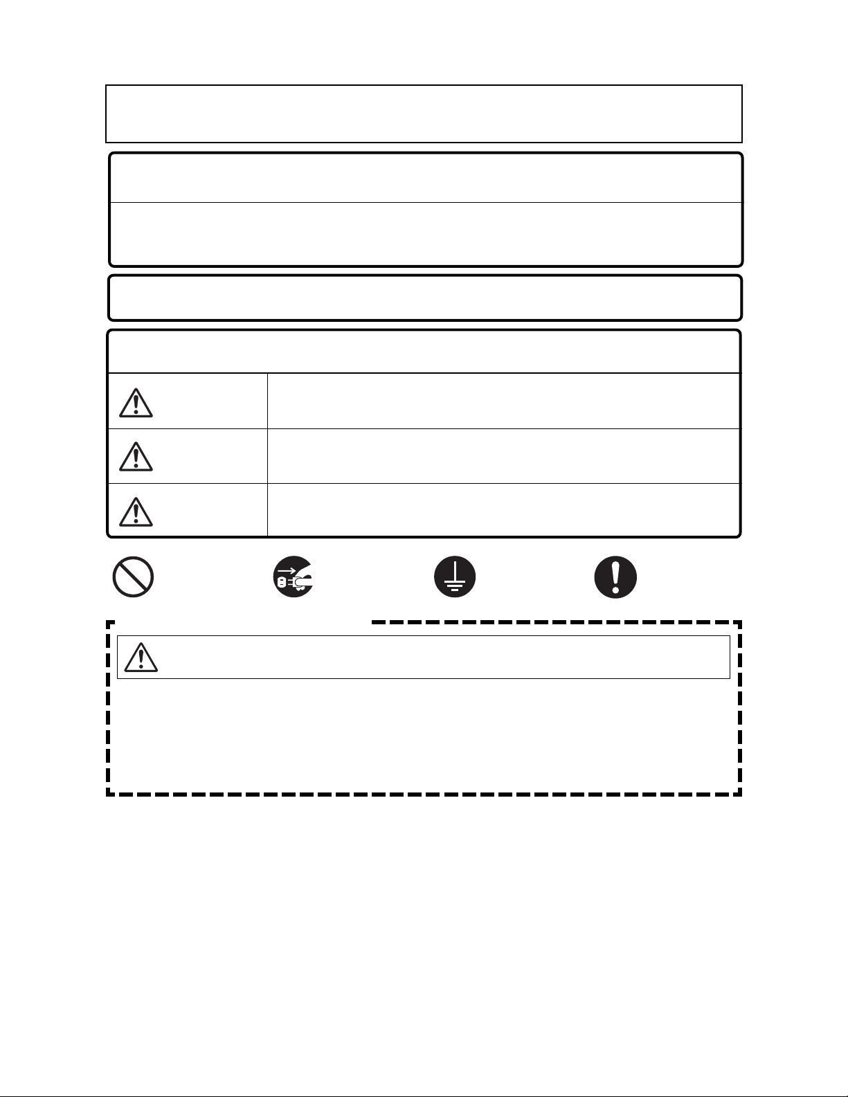
Potential dangers from accidents during installation and use are divided into the following three
categories. Closely observe these warnings; they are critical to your safety.
Icons warning of risk level
Danger
Warning
Caution
Remarks
Other icons
Electric
Shock.
Prohibited
If you detect a gas leak:
1. Do not try to light any appliance
2. Do not touch any electrical switch;
do not use any phone in your
building.
3. Immediately call your gas supplier
from a neighbor’s phone. Follow
the gas supplier’s instructions.
4. If you cannot reach your gas
supplier, call the fire department.
Denotes content that may result in instantaneous fire, serious injury
and even death when ignored.
Denotes content that may result in fire, serious injury and even
death when ignored.
Denotes content that may result in bodily injury and physical
damage when ignored.
The content following this icon is necessary to understand for safe
and easy use of this water heater.
High
Temperature.
No flame.
Be sure
to do.
Don’t
touch.
Danger
Ground.
Don’t
disassemble
the equipment.
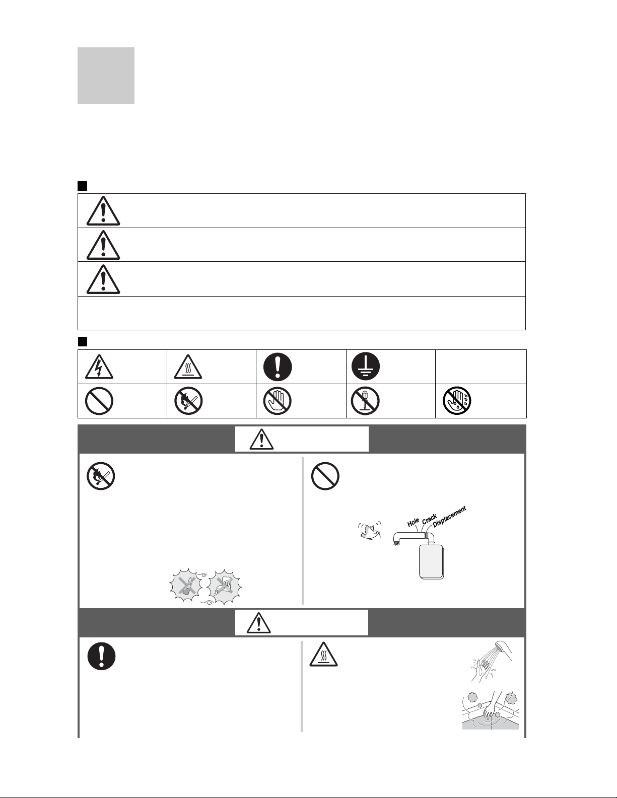
Do not use the water heater if
the exhaust pipe is displaced, has
holes, or is corroded.
Don’t touch
with a wet
hand.
Warning
If you detect abnormal combustion
or abnormal odors, or during an
earthquake, tornado or fire:
1. Turn off the hot water supply
2. Turn off the power to the water
heater
3. Turn off gas and water at the
main
4. Consult the nearest Noritz agent
Check the temperature
of the running hot water
before entering the
shower.
Check the temperature
before stepping into
the bath tub.
(Continued)
3
Important Safety Information-2
(Continued)
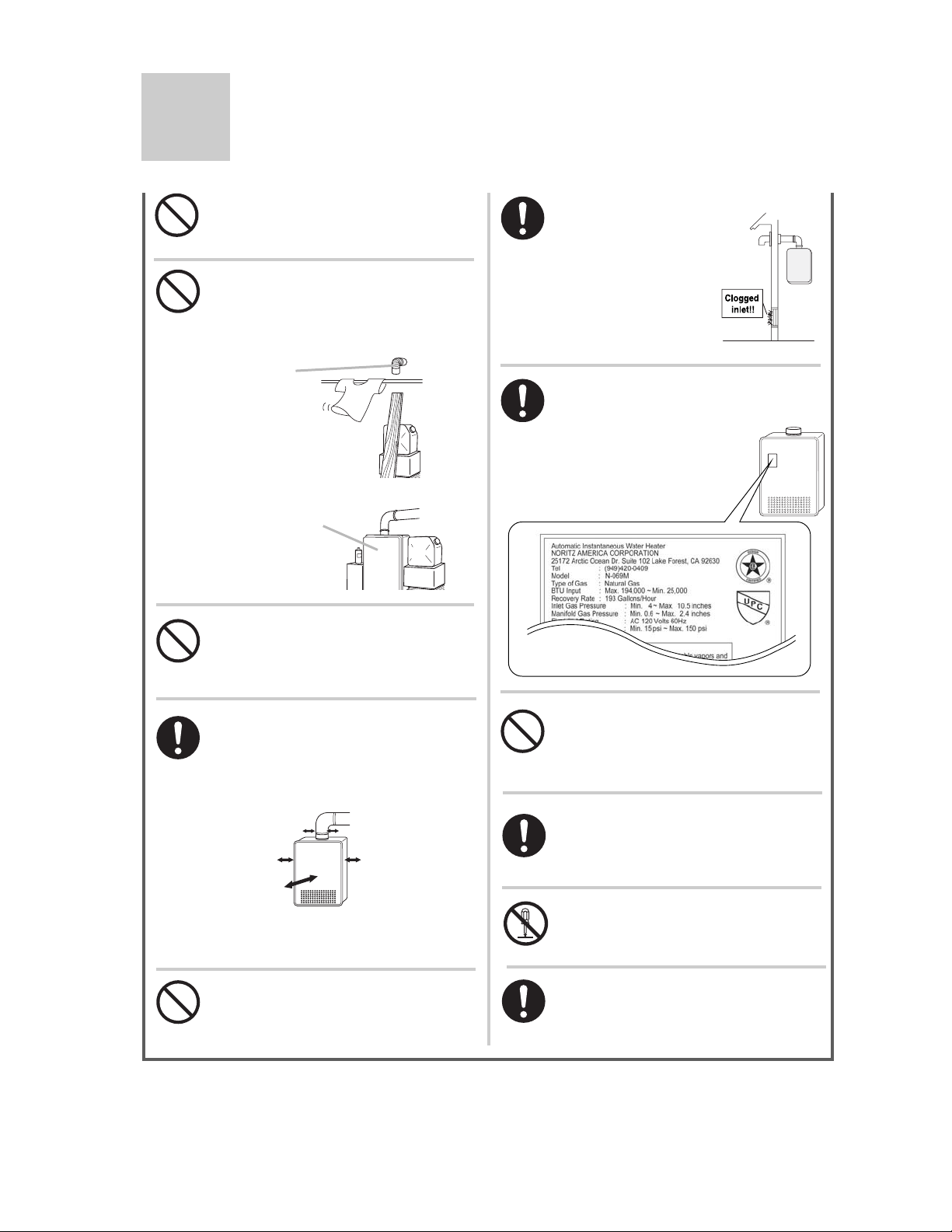
Do not turn off the water heater or
change the water temperature while
someone is bathing.
Do not place combustibles such as
laundry, newspapers, oils etc. near
the heater or the exhaust vent
terminal.
[When installing indoors]
Check the air supply
vent for dust or
obstructions.
Exhaust vent
terminal (indoor
installation)
Unit
Do not use combustible chemicals
such as oil, gasoline, benzene etc.
in the vicinity of the heater or the
exhaust vent terminal.
Leave the proper clearance between
the water heater and nearby objects
(trees, timber, boxes with flammable
materials etc.).
Min. 3" from
vent pipe
Left side:
Min. 2"
Front:
Sug. 24"
*
Indicates suggested clearances for
*
maintenance.
Right side:
Min. 2"
Be sure the gas/power supplied
matches the gas on the rating
plate.
For Natural Gas
Do not allow small children to play
unsupervised in the bathroom.
Do not allow small children to
bathe unsupervised.
Consult the nearest Noritz agent if
the water heater location needs to
be changed.
Contact a qualified service
technician for any necessary
repairs, service or maintenance.
4
Do not place or use a spray can
near the heater or the exhaust vent
terminal.
Contact Noritz before using with
a solar pre-heater.
Caution
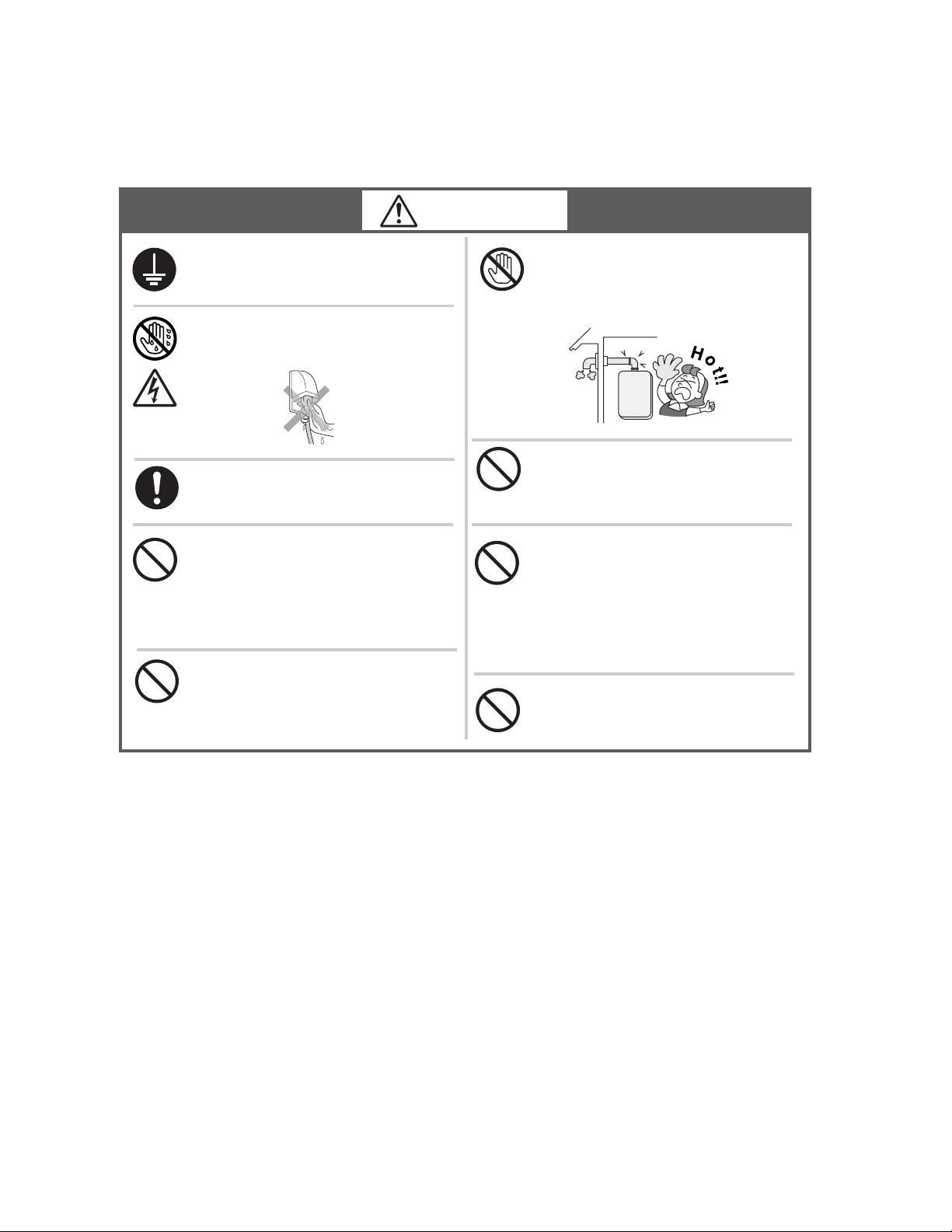
Be sure to electrically ground the
unit.
Do not touch the power cord with
wet hands.
Keep power cord free of dust.
Do not use a broken or modified
power cord. Do not bind, bend or
stretch power cords.
Do not scratch, modify, or subject
them to impact or force.
Do not use the water heater for
other than hot water supply,
shower and bath.
Do not touch the exhaust vent pipe
during or immediately after
operation of the water heater.
Do not use hair spray or spray
detergent in the vicinity of the
heater.
If this unit will be installed in a
salon or other location where hair
spray or aerosols will be used,
locate the unit in a seperate area
that is supplied with fresh air from
outdoors.
Do not install in locations where
excessive dust or debris will be
in the air.
5
Important Safety Information-3
Remark
Do not drink water that has been inside the
unit for an extended period of time. Do not
drink the first use of hot water from the
unit in the morning.
Clean the filter on the water inlet as
frequently as required by the quality of
your local water.
Keep the area around the unit clean.
If boxes, weeds, cobwebs, cockroaches etc. are in
the vicinity of the unit, damage or fire can result.
Do not install the equipment where the
exhaust will blow on walls or windows.
Treat hard, acidic or otherwise impure
supply water with approved methods to
ensure full warranty coverage.
Problems resulting from scale formation
are not covered by the warranty.
Check ignition during use and extinction
after use.
Do not run water through the unit when
unit is not on.
When discharging hot water, make sure the unit is
ON.
If water is run through the unit with the unit
OFF, water may condense inside the unit and cause
incomplete combustion or damage to the internal
electrical components.
This unit is only approved for installation
up to 4500 ft. above sea level.
For installations at higher elevations, contact Noritz
America for Instructions.
Do not disassemble the remote controller.
Do not use benzene, oil or fat detergents
to clean the remote controller.
This may cause deformation.
Do not get the remote controller wet.
Although it is water resistant, too much water can
cause damage.
Do not splash water on the remote
controller. Do not expose the remote
controller to steam.
Do not locate the remote controller near stoves or
ovens, this may cause damage or failure.
Preventing damage from freezing ( p.17)
Damage can occur from frozen water within the
device and pipes even in warm environments.
Be sure to read below for appropriate measures.
Repairs for damage caused by freezing are not
covered by the warranty.
Take necessary measures to prevent
freezing of water and leakage of gas when
leaving the unit unused for long periods of
time. (
If it is snowing, check the air inlet, exhaust
gas vent and exhaust vent terminal for
blockage.
p.18)
6
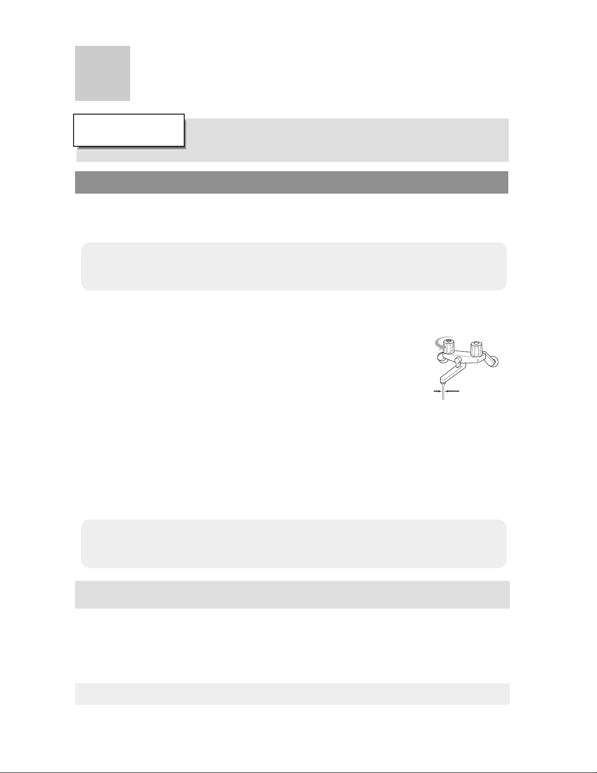
For single-handle fixtures or valves, discharge
water setting the handle completely
to the water side.
Do not use parts other than those specified
for this equipment.
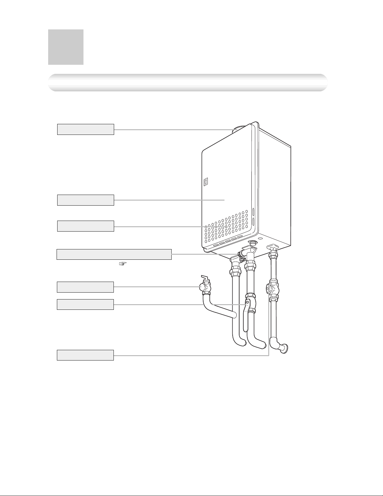
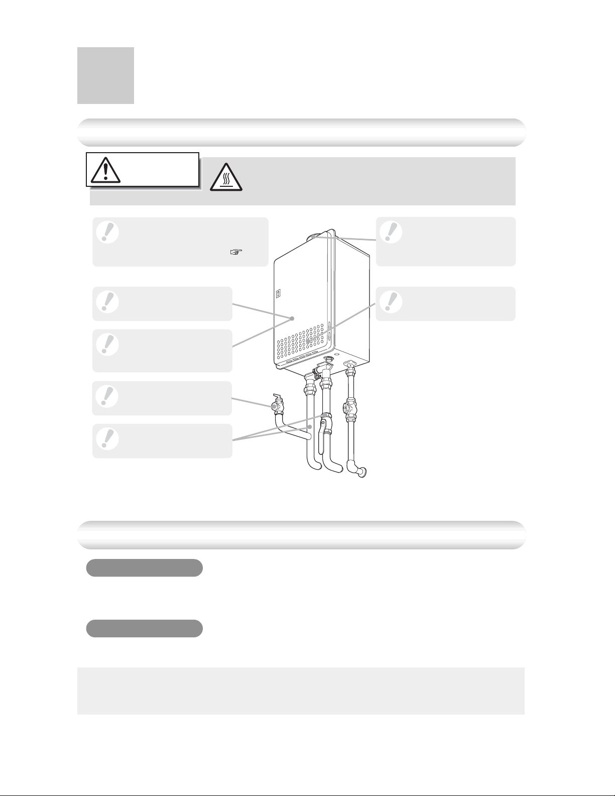
General Parts
Main Unit
Indoor/Outdoor Wall Mounted, Power Vented Model
Flue Collar
Front Cover
Air Inlet
Water Drain Valve (with Water Filter)
(Inside Water Inlet) (
Pressure Relief Valve
Water Supply Valve
Gas Supply Valve
* The above illustration shows an example of installation.
The exact installation configuration may be slightly different.
p.20)
7
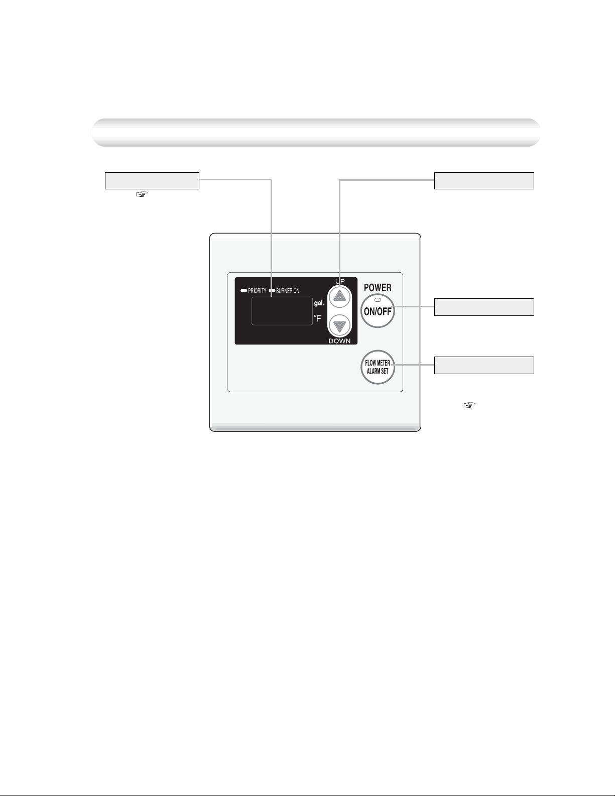
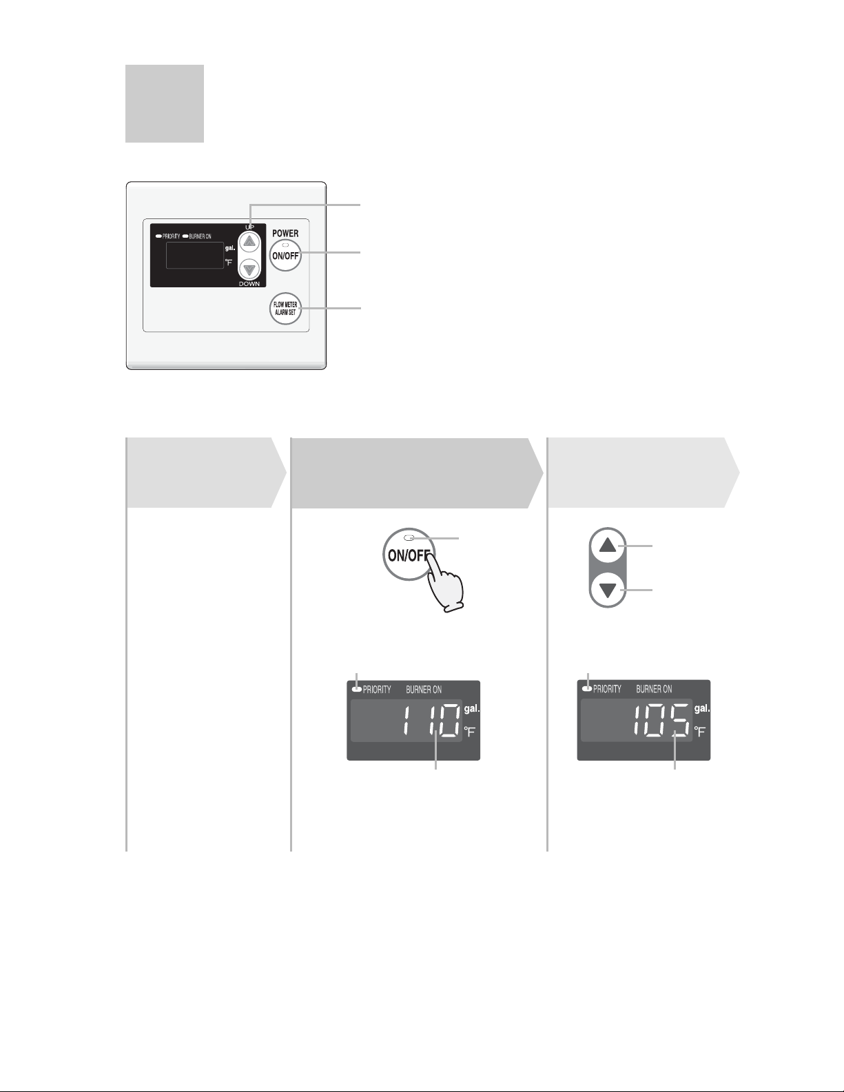
Remote Controller (RC-7646M-2)
Display
( next page)
Setting Buttons
For setting the hot
water temperature,
the flow meter alarm,
and other settings.
Power On/Off Button
For turning the
heater on and off.
Flow Meter Alarm Set Button
For setting the flow
meter alarm.
( p.14 and 15)
8
* Before use, remove the protective sheet from the remote controller surface.
* The unit has been shipped from the factory with the remote controlset at 110°F.
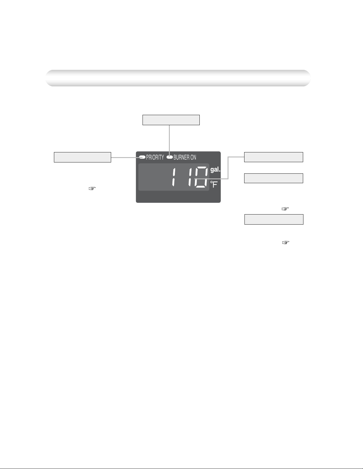
Display
The illustration below shows the remote controller display. What is actually displayed
depends on how the water heater is set.
Burner On Indicator
Priority Indicator
When this indicator
is lit, the hot water
temperature can be
set. ( p.13)
Temperature Setting
(Ex.: 110°F)
Flow Meter Setting
The display will flash
after hitting the flow
meter alarm set button.
( p.15)
Error Code
A number will flash if
a failure occurs.
( p.24)
9
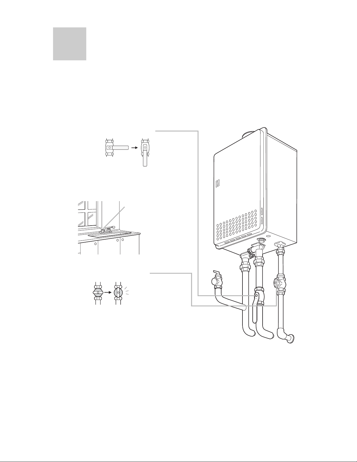
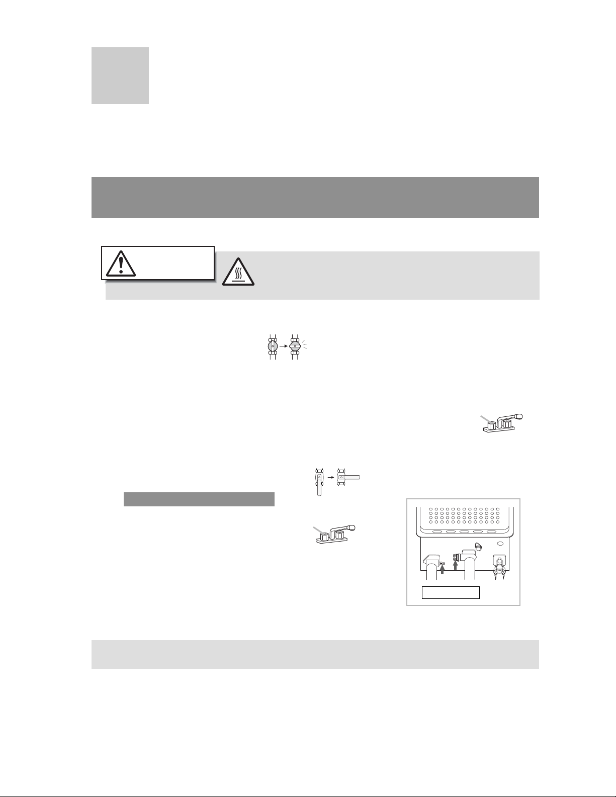
Initial Operation
Before the first use of your water heater, make the following preparations.
Follow steps
Open the water supply valve.
1
CLOSED
Open a hot water fixture to confirm that
water is available, and then close the
2
fixture again.
1 through 4.
OPEN
Hot water fixture
10
Open the gas supply valve.
3
Turn on the power.
4
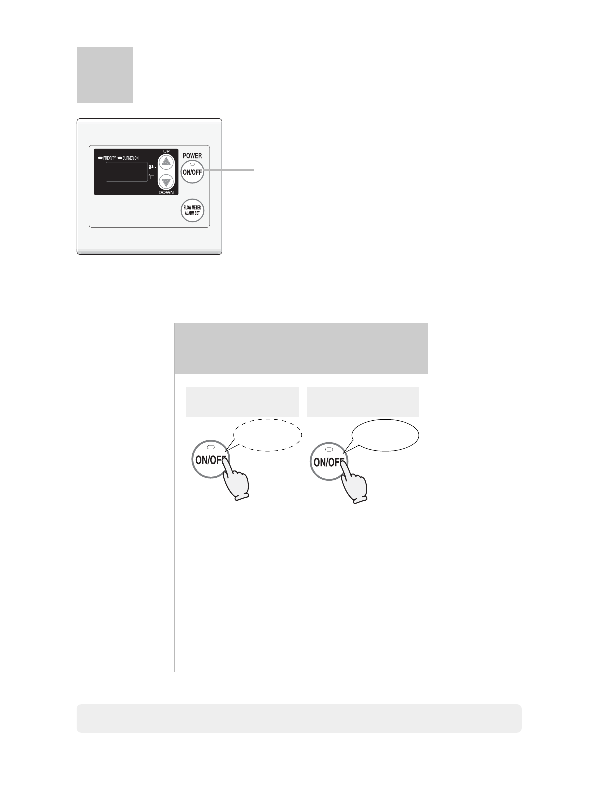
How to Use (Using the remote controller)
Muting the Remote Controller
The remote controller will emit a sound
when any button is pushed. This sound
can be muted if it is desired.
* Initial factory setting is with sound
1
With the remote controller
off, hold the Power On/Off
1
Button for five seconds.
Muted
No sound
after 5 sec.
Sound
Tone sounds
after 5 sec.
The flow meter alarm cannot be muted.
11
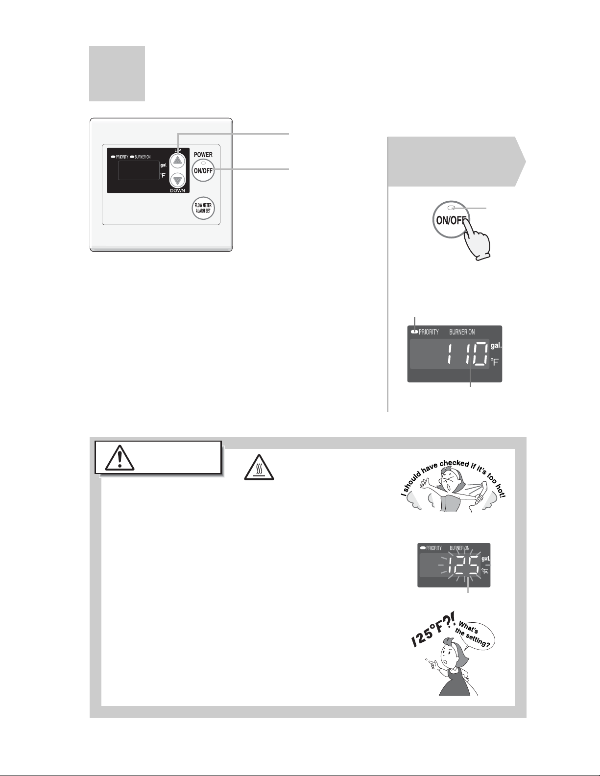
How to Use (Using the remote controller)
Setting and Using the Water Heater
(Starting with the Power Off)
2
Press the Power
On/Off Button.
1
1
The temperature will be
displayed on the remote
control thermostat.
On
On
Caution
To prevent scalding:
High Temperature
Temperatures above 125 °F can scald.
• Check the water temperature by hand before bathing or
showering.
• When setting the unit to 125°F or higher, the
temperature display will flash for 10 seconds as a high
temperature warning.
• Take caution when using the unit again after setting to
125°F or higher. Always check the set temperature
before use.
• Do not allow anyone to change the water temperature
while hot water is running.
Previous set
temperature
(Ex.: 110°F)
Remote Controller Display
Flashes for 10 sec
12
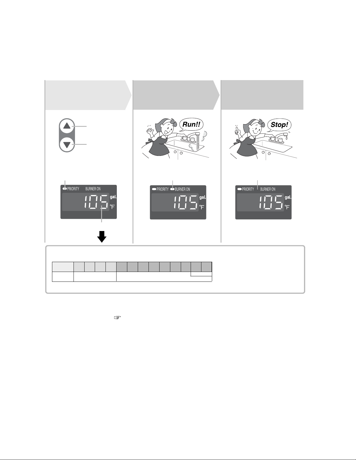
Set temperature.
Always check the
2
temperature setting
(
before use.
Hot
Cold
)
Turn on hot
water.
3
Turn off the hot
water.
4
Check the indicator lights.
Water temperature
The temperature settings below are examples. The temperature setting
:
(°F
necessary depends on the usage, the length of piping and the time of year.
100 105 110 115 120 125 130 135 140 145 150 160 170 176
Washing
dishes, etc.
* For most residential applications, the recommended setting temperature is 120°F or less.
For applications that occasionally require a higher temperature setting, locate the remote controller
in a convenient location ( p.61).
* Consult local codes for minimum operating temperatures.
Shower, hot water
supply, etc.
High temperature
*Initial factory setting is 110°F
On
)
Off
If fixtures incorporate mixing
valves, set the temperature
higher than usual.
Only N-069M
13
How to Use (Using the remote controller)
Flow Meter Alarm
2,3
1
3
(Starting with the power off)
Preparation
1. Plug the bath drain.
Press the Power
On/Off Button
1
On
The temperature will be displayed
on the remote control thermostat.
On
Previous set temperature
(example:110°F)
Set temperature.
Always check
2
temperature setting
(
before use.
Hot
Cold
Check the indicator lights.
Water temperature
)
14
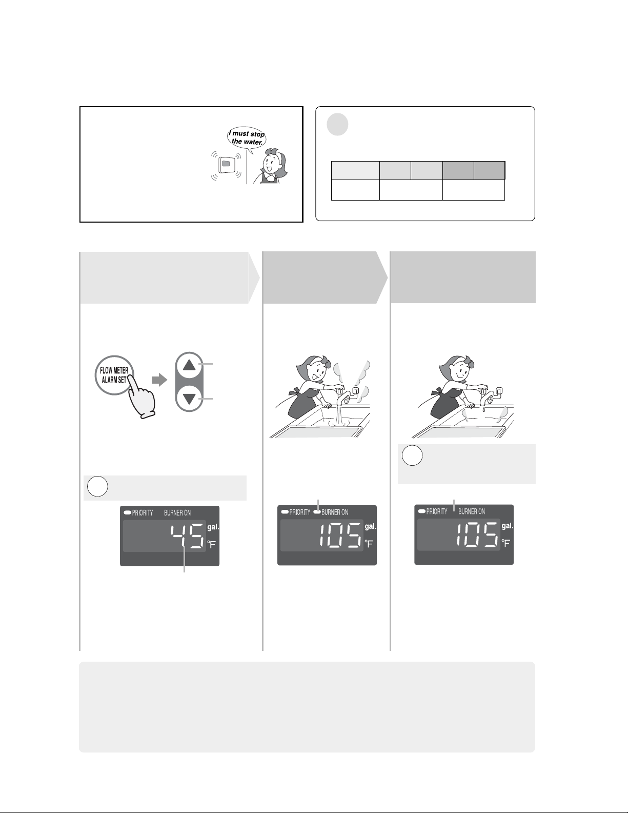
An alarm will sound for ten
seconds when the flow
reaches the set level.
Water Temperature
The temperatures settings below are only examples. The
:
temperature setting necessary will depend on the usage,
(°F
the length of piping and the time of year.
100 105 110 115 120
)
The water will continue to run unless it is
manually turned off.
To set the flow meter alarm:
Adjust flow meter
3
alarm setting.
Press the flow meter alarm set button
(the setting will flash on the display)
and adjust with the setting buttons.
Increase
Decrease
Choose the flow meter alarm setting
from the following options: 10 - 60
(In 5 gallon intervals), 70 - 100 (In
10 gallon intervals), or 990 gallons.
The alarm will not sound if
Note:
it is set for 990 gal.
4
Turn on hot
water.
On
Warmer HotWarm
* Initial factory setting: 110°F
Turn off the hot
water when the
5
alarm sounds.
The alarm will sound when
the set level has been
reached. Stop the water.
The alarm will not
Note:
sound if it is set for
990 gal.
Off
Flow meter setting will be flashing
(ex. 45 gal.)
* The level can only be adjusted
while the indicator is flashing.
* After ten seconds, the remote
will again display the temperature.
If the flow meter alarm is being used to indicate when a tub is full:
• If any hot water is being used besides what is going into the tub, the alarm will sound before
the tub is full.
• If there was water in the tub before the fill began, or if the water is not shut off manually when
the alarm sounds, the tub may overflow.
• If there was water in the tub before the fill began, the temperature in the tub after it is full may
be different from the temperature setting.
15
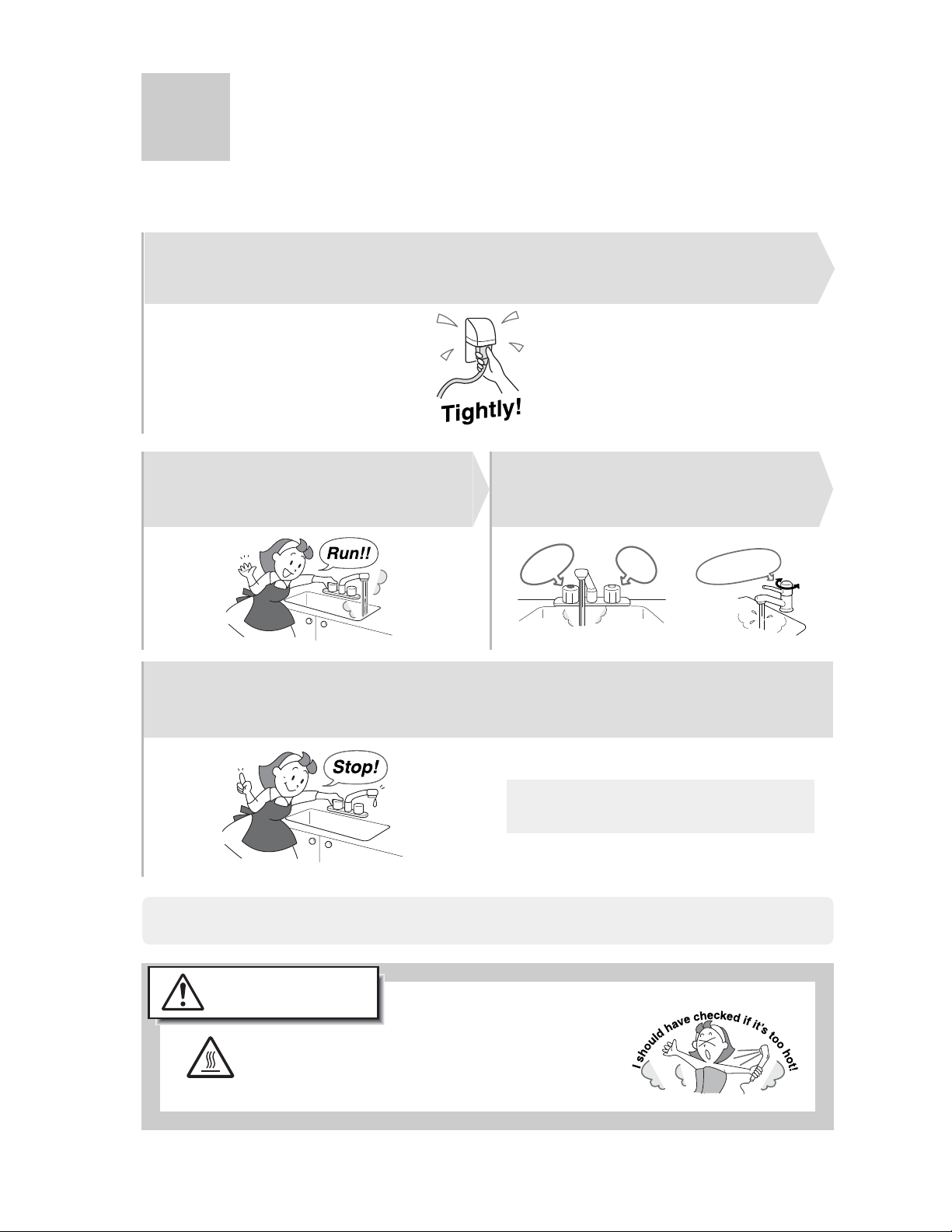
How to Use (Not using the remote controller)
Setting and Using the Water Heater
The factory temperature setting is 120°F (fixed). Mix with cold water with a mixing valve
or at the fixture for desired temperature.
Check that electrical power is connected.
1
Turn on hot water.
2
scalding.scalding.
4
Turn off the hot water.
If you want to the temperature to be changed to 130°F or 140°F, contact the installer or Noritz.
Mix for desired temperature.
3
W
a
te
Hot water
The electrical power does not need to
be disconnected between uses.
r
Te m
pe
rature
16
WARNING
High Temperature
To prevent scalding.
Check the temperature of the running hot
water before using. Temperatures above
125°F can scald instantly.
Preventing Damage from Freezing-1
Remarks
* Damage can occur from frozen water within the device and pipes even
in warm environments. Be sure to read below for appropriate measures.
* Repairs for damage caused by freezing are not covered by the warranty.
Freezing is prevented within the device automatically by the freeze-prevention heater
Freezing cannot be prevented when the power plug is unplugged. Do not remove the power
plug from the wall outlet.
(Freezing will be prevented regardless of whether the operation switch is ON or OFF.)
* The freeze prevention heaters will not prevent the plumbing external to the unit from freezing.
Protect this plumbing with insulation, heat tape or electric heaters, solenoids, or pipe covers.
If there remains a freezing danger, contact the nearest Noritz agent.
Take the measures below for extremely cold temperatures*. <Only using the remote controller>
(outside temperature including wind chill factor less than 5°F)
This method can protect not only to the heater, but also to the water supply,
water piping and mixing valves.
1. Turn off the power.
2. Close the gas supply valve.
3. Open a hot water fixture, and keep a small stream of hot water
running. (400cc/minute or about 1/4" thick.)
* If there is a mixing valve, set it to the highest level.
* When linking multiple units, discharge water equivalent to
400 cc/minute per unit.
4. The flow may become unstable from time to time. Check the flow
30 minutes later.
* In general, it is not advisable to run water through the unit when
it is OFF (see p. 6), but in this case freeze prevention is more
important.
Hot Water Fixture
1/4" thick
* Remember to set mixing valves and fixtures to their original levels before using the unit again
to prevent scalding.
* If there is still a chance that the unit will freeze, drain the unit as on the next page.
If water will not flow because it is frozen
1. Close the gas and water valves.
2. Turn off the power button.
3. Open the water supply valve from time to time to check whether water is running.
4. When the water is flowing again, check for water leaks from the equipment and piping
before using.
If the heater or the piping is frozen, do not use the heater or it may get damaged.
17
Preventing Damage from Freezing-2
If the water heater will not be used for a long period of time,
Drain the water.
Drain the water as follows:
Caution
High Temperature
Drain water into a bucket to prevent water damage.
1. Close the gas valve.
2. (1) Turn the power on. <Using the remote controller>
(2) Turn and leave open the hot-water tap for more than 1 minute and close.
* If multiple units are being used, drain one minute for each unit.
* An 11 Error Code may appear on the remote controller.
This is not a malfunction of the unit. Do not turn Power ON/OFF Button OFF.
3. Close the water supply valve, disconnect
the electrical power supplied to the unit.
Do not touch with wet hands.
4. Fully open all hot water fixtures.
To avoid burns, wait until the equipment cools down
before draining the water. The appliance will remain hot
after it is turned off.
Fixture
Fixture
18
5. Open all drain plugs and drain the water out
of the unit.
6. When the water is completely drained, replace all drain
plugs and close the hot water fixtures.
Turning the Unit Back On
1. Check that all drain plugs are inserted.
2. Check that all hot water fixtures are closed.
3. Follow the procedure on p.11 “Initial operation”, steps 1 through 4.
Drain Plugs
Regular Maintenance-1
Periodic Inspection
Caution
High Temperature
For laundry, newspaper, timber,
Check
oil, spray cans and other
combustible materials. ( p.4 )
For abnormal sounds
Check
during operation.
For abnormalities in
Check
external appearance,
discoloration or flaws.
For proper operation of
Check
pressure relief valve.
For water leaks from the
Check
equipment and piping.
To avoid burns, wait until the equipment cools down
before draining the water. The appliance will remain
hot after it is turned off.
For dust and soot in
Check
the exhaust vent or
exhaust vent terminal.
For dust or debris in
Check
the air inlet.
Periodic Maintenance
Equipment
Wipe the outside surface with a wet cloth, then dry the surface. Use a neutral detergent to
clean any stains.
Remote Controller
Wipe the surface with a wet cloth.
• Do not use benzene, oil or fatty detergents to clean the remote controller;
deformation may occur.
• The remote controller is water resistant but not water proof. Keep it as dry as possible.
19
Regular Maintenance-2
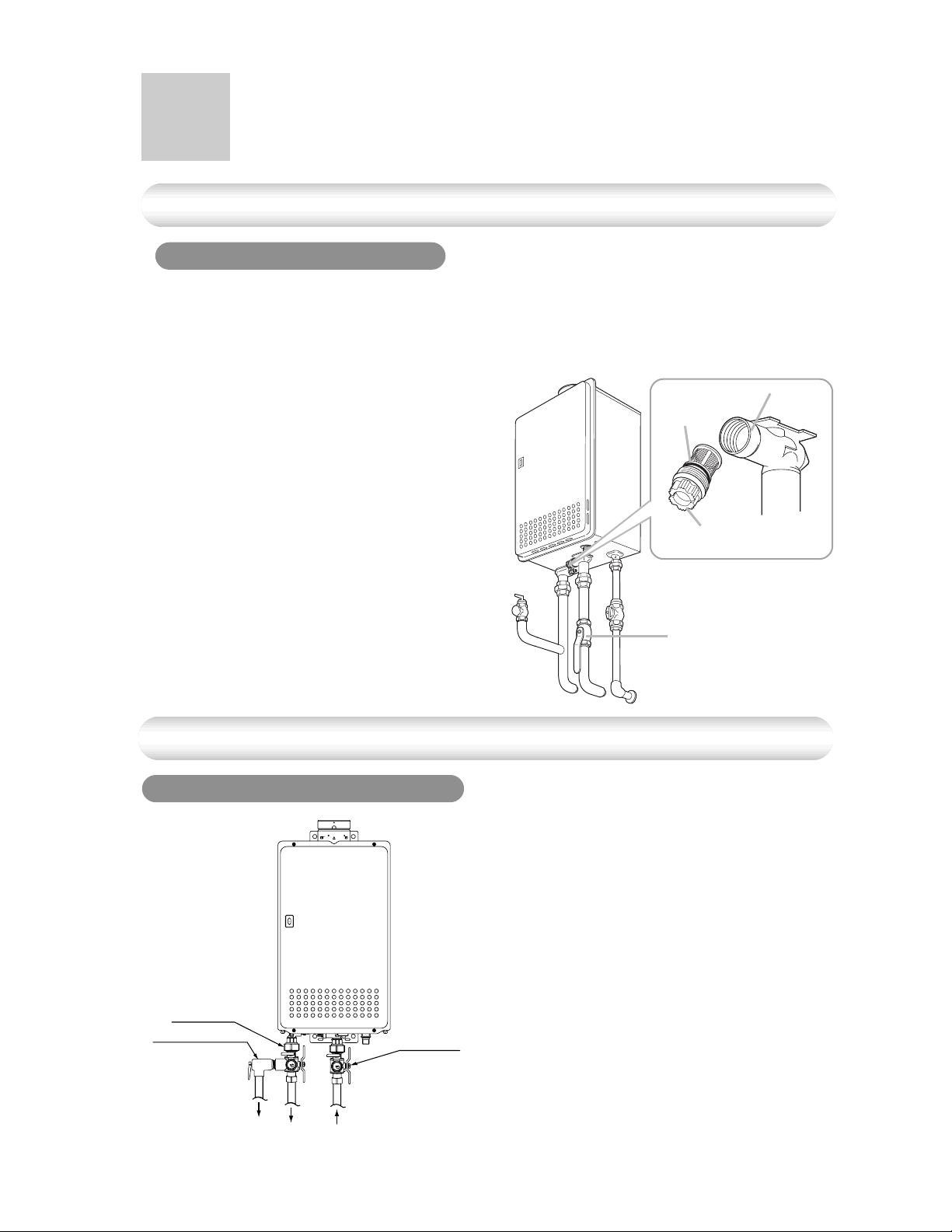
Periodic Maintenance
Water Drain Valve (with Water Filter)
If the water drain valve (with water filter) is covered with debris, the hot water may not run
smoothly, or the unit may put out cold water. Check and clean the filter as explained below.
* To avoid burns, wait until the equipment cools down before draining the water.
The appliance will remain hot after it is turned off.
1. Close the water supply valve.
2. Open all hot water fixtures.
3. With a bucket ready, remove the inlet and outlet
drain plugs (about 0.2 gal. will drain out)
4. Take the water drain valve (with water filter) out
of the inlet. (See illustration to right).
5. Clean the water drain valve (with water filter) with
a brush under running water.
6. Replace the water drain valve (with water filter)
and close the drain plugs.
(Take care not to lose the packing.)
7. Close all hot water fixtures.
8. Open the water supply valve and check that
water does not leak from the drain plugs or water
drain valve (with water filter).
Optional Maintenance
Water Heater Service Valves (IK-WV-1)
Inlet
Packing
Drain Plug
(with filter)
Water Supply
Valve
20
Hot Water
Service Valve
Pressure Relief Valve
Drain
Water Outlet
Water Intlet
Cold Water
Service Valve
* Isolator valve kits may be purchased as an
accessory from Noritz (Part #IK-WV-1).
They allow for full diagnostic testing and easy
flushing of the system.
* The kit includes two full port isolation valves
and a pressure relief valve for the hot side.
Contact Noritz for more information.

Troubleshooting-1
Initial Operation
Unit does not attempt to ignite
when water is running.
Unit attempts to ignite but fails
Hot water is not available
when a fixture is opened.
No water is available when
a fixture is opened.
The hot water is not the correct
temperature.
Water takes time to become hot
when turning the hot water fixture.
• Is water running?
• Check for reversed plumbing or crossed pipes.
• Check the water drain valve filter. ( p.20 )
• Reset unit and try again. There may be air in the gas line.
• Have a professional check the gas supply pressure.
Temperature
• Are the gas and water supply valves fully open?
• Is the water supply cut off?
• Is the hot water fixture sufficiently open?
•
Is the gas being cut off by the gas meter?
(Can other gas devices such as stoves be used?)
• (For LP) Is there enough gas in the tank?
(Can other gas devices such as stoves be used?)
• Is the water drain valve filter clogged? ( p.20)
• Is the power button turned on?
• Is the water supply cut off?
• Is the heater frozen?
• Is the hot water fixture sufficiently open?
• Have you allowed enough time for the cold water in the
pipes to drain out?
The water is too hot.
The water is not hot enough.
• Are the gas and water supply valves fully open?
• (Using the remote controller) Is the water temperature
setting appropriate? (
• If the water supply temperature is high, it is possible
for the temperature to be higher than the temperature
set on the remote controller.
• If only a small amount of hot water is demanded, it is
possible for the temperature to be higher than the
temperature set on the remote controller.
• Are the gas and water supply valves fully open?
• (Using the remote controller) Is the water temperature
setting appropriate? (
• If the amount of hot water required is very high, it is
possible for the temperature to be lower than the temp erature set on the remote controller.
Decrease the amount of hot water passing through the unit
and the temperature should stabilize.
p.12 and p.13)
p.12 and p.13)
21

Troubleshooting-2
Temperature
The water is cold when only a
single fixture is open.
Fluctuations in hot water
temperatures.
The amount of hot water at a
certain fixture is not constant.
• The unit will not heat the water if the flow rate is less than
0.5 gallons per minute.
Open the fixture more or open other fixtures so that a greater
flow passes through the unit, and the unit should begin
heating again.
• Set water temperature at 115
to use a higher flow of hot water thus meeting the minimum
flow requirement of 0.5 gpm.
• Clean the water filter of any debris (
Amount of Hot Water
• When hot water is demanded at other fixtures, the
amount available may be reduced. The maximum flow
available from this unit is a 45°F temp. rise.
for N-069M=6.9 GPM / for N-063S=6.3 GPM
• Pressure fluctuations and other plumbing conditions can
cause the temperature and pressure at a fixture to be
unstable, but it should stabilize after a short time.
• There are some types of hot water taps that discharges large
volumes of hot water at first but stabilize after time.
• To keep the temperature stable, the heater limits the
amount of water that can flow through it to a small
amount initially, but the amount increases over time.
°F to 120°F. This will allow you
p.20)
22
The amount of hot water in the tub
is less/more than the set amount.
The flow meter alarm does not
sound even when filled to the set
amount.
Amount of hot water available
has decreased over time.
• When hot water is used for other fixtures while filling the
bath tub, the tub will not fill as much.
• If there is water in the tub already, or when filling is stopped
and restarted, the tub will fill more.
• The flow meter alarm is set to sound when hot water
is continuously discharged for the set volume of water.
If mixing valves are used, or if cold water is mixed with hot
water at the fixture, the tub will fill more than the setting
of the flow meter alarm.
• Is the water filter clogged? (
p.20)

Remote Controller
The light on the power button
does not come on.
The water temperature changes
after a power failure or when the
power is disconnected.
The fan can be heard after
operation is stopped.
A motor can be heard when turning
the unit ON or OFF, when opening
or closing a fixture, or after the unit
has been running for a while.
• Has there been a power failure?
• Is the power connected properly?
• The temperature setting and the flow meter alarm setting
may both need to be reset after a power outage.
Sounds
• These noises indicate the proper operation of devices
which are designed to let the unit reignite more quickly,
and ensure the water temperature is stable.
Other
The Heater stops burning during
operation.
exhaust vent on a cold day.
The hot water is turbid.
The water appears blue
The bath tub/wash-basin has turned
blue
• Are the gas and water supply valves fully open?
• Is the water supply cut off?
• Is the hot water fixture sufficiently open?
• Is the gas being cut off by the gas meter?
(Can other gas devices such as stoves be used?)
• (For LP) Is there enough gas in the tank?
(Can other gas devices such as stoves be used?)
• This is normal. The white smoke is actually steam.White smoke comes out of the
• This is harmless. Small bubbles appear as the air in the
water is heated and depressurized rapidly to
atmospheric pressure.
• Coloration to a blue color may be noticed from small
traces of copper ion contained in the water and fat
(furring). However, there are not problems concerning
health. Coloration of the bath tub/wash-basin can be
prevented by cleaning frequently.
23

Troubleshooting-3
åÃè·ï\é¶Ç Ç®í≤Ç◊Ç≠ÇæÇ≥Ç¢åÃè·ï\é¶Ç Ç®í≤Ç◊Ç≠ÇæÇ≥Ç¢
Check for an Error Code or Flashing Light on the Unit
[Error displays on the remote controller]
If there is a problem with the unit, a numerical error code will flash on the remote controller.
If this occurs, take appropriate measures as listed below.
When an error code appears, the display and the operation light will flash
together.
Flashing
Remote Controller
Error Code Cause Action
Ignition error
Abnormal combustion,
low gas supply pressure
Check whether the gas valve is open. Press the power
button to turn the unit off, open a hot water fixture,
and turn the unit back on. If the flashing number
doesn't return the problem is solved.
Have a professional check the gas supply pressure.
Contact the nearest Noritz agent.
Contact the nearest Noritz agent.Abnormal combustion
[Error displays on the lamp]
If there is a problem with the unit, a lamp will flash on the front of the unit.
If this occurs, take appropriate measures as listed below.
Lamp Cause Action
ON
OFF
Unit abnormality
Contact our sales agent if:
• Any other error code appears.
• An error code is indicated again after the above actions were followed.
• There are any other questions.
Check whether the gas valve is open. Close
the hot water fixture, and then open it again.
If the lamp does not begin flashing again, the
problem is solved.
24

Follow-up Service
Requesting Service
First follow the instructions in the troubleshooting section (p.21 to p.24).
If the error is not corrected, contact our sales agent.
We will need to know:
The Model ................ (check the rating plate)
*See p.4 for the location of the label
Date of purchase ..... (see the warranty)
Details of problem ... (flashing error codes,
etc., in much detail as possible)
Your name, address, and telephone number
Desired date of visit
* A request for service may be rejected if the water heater is installed
in a location where working on the unit may be dangerous. Contact a
plumber.
Warranty
A warranty registration card is included separately.
Be sure that the plumber, date of purchase and other necessary items are filled in.
Read the content carefully, and keep the warranty card in a safe place.
For repairs after the warranty period, there will be a charge on any service, and service will only
be performed if the unit is deemed repairable.
Period of Time for Stocking Repair Parts
Noritz will stock repair and maintenance parts for this unit for a minimum of seven years after
production has ceased.
Reinstallation
If you want to reinstall the appliance at a different location, confirm that the gas and power
supply indicated on the rating plate are available at the new location. If you are not sure,
consult the local utility company.
If you move to a region that uses a different type of gas, conversion and adjustment of the
appliance will be necessary. This work must be performed by Noritz and will be charged for
even during the warranty period.
25

Specifications
Specifications
• Specifications may be changed without prior notice.
• The capacity may differ slightly, depending on the water
pressure, water supply, piping conditions, and water temperature.
Item
Model Name
Type
Ignition
Operating Pressure
Minimum Flow Rate
Dimensions
Weight
Water Holding Capacity
Connection Sizes
Power Supply
Materials
Safety Devices
Accessories
Installation
Air Supply/Exhaust
Water Inlet
Hot Water Outlet
Gas Inlet
Supply
Consumption
Casing
Flue Collar
Heat Exchanger
Specification
N-069M
Indoor/ Outdoor, Wall Hanging
Power Vented
Direct Ignition
15-150 PSI
0.5 GPM
23.6"(Height) x 13.8"(Width) x 9.4"(Depth)
46 lbs.
0.2 Gallon
3/4"
3/4"
3/4"
120 VAC (60Hz)
NG : 71W
LP : 71W
Freeze Prevention 125W
Zincified Steel Plate/Polyester Coating
Copper Sheeting, Copper Tubing
Flame Rod, Thermal Fuse, Lightning Protection
Device (ZNR), Electric Leakage Prevention Device
(GFCI), Overheat Prevention Device, Freezing
Prevention Device, Fan Rotation Detector
Remote Controller,
Remote Controller Cord,
Anchoring Screws
NG : 65W
LP : 65W
Freeze Prevention 125W
Stainless Steel
Anchoring Screws
N-063S
44 lbs.
26
Item
Gas Consumption
Maximum Hot Water Capacity
Capacity Range
Temperature Settings
Default Temperature Options
Performance
Maximum Performance
Minimum Performance
45°F Rise
N-069M
NG : 194,000 btuh, LP : 194,000 btuh
NG : 25,000 btuh, LP : 25,000 btuh
6.9 Gal./min.
0.5-7.9 Gal./min.
100-150°F (In 5°F intervals),
160, 170, 176°F (14 Options)
120, 130, 140, 176°F
(Original is 120°F)
6.3 Gal./min.
0.5-6.3 Gal./min.
(Using the remote controller)
100-150°F (In 5°F intervals),
160°F (12 Options)
120, 130, 140°F
(Original is 120°F)
N-063S

External outfitting
072
072
011
For N-069M only
007
001
015
012
002
013
014
037
034
074
071
016
005
004
003
015
002
035
For N-063S only
007
020
010
073
27

External outfitting
Part Nos. Part Names Order Nos. Q'ty/unit
001 N-069M Front set-AS SBP7439 1
002 Front packing1 EAA EAAL002 2
003 Caution label 1 EAU EAUK003 1
004 Caution label 2 EAU EAUK004 1
005 Connection diagram label EHU EHUK002 1
007 Case EHU EHUA002 1<N-069M>
Case EHV EHVA002 1<N-063S>
010 Grommet CXP CXPA026 1
011 Case top cover 2 EDL EDLA005 1
012 Case top cover EHU EHUA006 1
013 Case top packing EHU EHUL001 1
014 Exhaust sylinder packing EDL EDLL002 1
015 Long front packing AAP AAPL017 2
016 Lamp seal plate DEC DECK008 1
020 Wiring coupling BXK BXKA022 1
034 Junction box set EHU EHUA008 1
035 Junction box packing EHU EHUL002 1
037 Air themistor BWC BWCH003 1
071 Cross recessed truss type3 EVERTIGHT tapping screw with PW 4X12
072 Cross & straight recessed round-head collar/protrusion S TIGHT tapping screw 4X8
073 Cross recessed round-head collar type3 EVERTIGHT tapping screw 4X12
074 Cross recessed round-head collar N-tapping screw 4X8
28

Combustion unit and gas route
110
162
101
165
166
125
169
127
133
132
126
128
134
127
074
106
145
107
167
074
103
115
105
116
104
102
111
100
163
074
117
074
167
168
166
168
164
138
134
140
118
113
112
074
074
074
114
29

Combustion unit and gas route
Part Nos. Part Names Order Nos. Q'ty/unit
100 Combustion tube set EHU EHUC010 1
101 Suction air joint packing DTJ DTJL001 1
102 Ignition plug CZL & packing DLK SET-V SBC7684 1
103 Flame rod & packing DLK SET-V SBC7685 1
104 Plug packing (for B) DLK SAB2715 1
105 Plug mounting plate (for B) DLK DLKC029 1
106 Burner sensor Q & packing DWD SET-V SBF7103 1
107 Burner sensor packing DWD DWDL005 1
110 Main damper11 DTJ DTJC041 1
111 Fan packing Q DTJ DTJL004 1
112 Fan flange DTJ DTJF035 1
113 Fan motor EHU-A EHUF031 1
114 Bell-mouth o40 DTJ DTJF043 1
115 Mounting plate for igniter DTJ DTJA015 1
116 Igniter CRP CRPJ002 1
117 High-voltage cord L350 ALS ALSJ079 1
118 Conduit guard packing DTJ DTJL010 1
125 Manifold LPG EHU SET-AS SBP7440 1<LPG>
Manifold NGA EHU SET-AS SBP7441 1<NGA>
126 Manifold seal packing top DTJ DTJL005 1
127 Manifold seal packing side DTJ DTJL007 2
128 Manifold seal packing bottom DTJ DTJL006 1
132 Gas mech. S16D EDN SET-V SBE7833 1
133 O-ring P18 2110903 2
134 O-ring P28 1648306 2
138 Gas coupling EHU EHUE011 1
140 Gas fitting 20A SET EHU EHUE021 1
145 Conduit R10 EHU EHUJ004 1
30
162 Cross recessed round-head N-tapping screw 4X8
163 Cross recessed round-head collar N-tapping screw 4X12
164 Cross recessed truss machine screw with PW M4X12
165 Cross recessed round-head type3 EVERTIGHT tapping screw 5X16
166 Cross recessed hexagon head machine screw M4X8
167 Cross recessed round-head collar N-tapping screw 4X10
168 Cross recessed round-head machine screw M5X12
169 Cross recessed round-head SPAKmachine screw with guide M4X12

Hot-water feed route for N-069M only
400
416
407
409
419
402
401
423
445
429
444
446
443
402
442
461
419
432
431
404
162
402
402
415
425
465
464
418
074
426
403
429
419
417
427
444
419
417
448
410
462
073
(Thermal fuse rounding procedure)
(Left side view)
401
407 409
452
451
(Front side view)
Thermal fuse fastener
402
Freeze preventive heater
416
430
Heater fastener
415
418
402
418
(Right side view)
466
462
436
437
438
410
(Rear side view)
Thermal fuse fastenerThermal fuse fastenerThermal fuse fastener
402
Thermal fuse
435
073
403
31

Hot-water feed route for N-063S only
400
407
409
402
401
423
461
402
447
444
441
446
445
404
162
402
402
425
465
464
074
426
403
429
419
427
444
32
429
419
416
462
(Thermal fuse rounding procedure)
(Left side view)
401
407 409
419
417
410
073
(Front side view)
Thermal fuse fastener
402
Freeze preventive heater
448
452
451
Heater fastener
(Right side view)
402
462
415
436
410
418
435
437
402
417
438
(Rear side view)
Thermal fuse fastenerThermal fuse fastenerThermal fuse fastener
Thermal fuse
073
403

Hot-water feed route for N-069M only/Hot-water feed route for N-063S only
Part Nos. Part Names Order Nos. Q'ty/unit
400 Heat exchanger & Exhaust box EHU SET-AS SBP7442 1<N-069M>
Heat exchanger & Exhaust box EHV SET-AS SBP7443 1<N-063S>
401 Thermal fuse fastener CZL CZLH005 1
402 Thermal fuse fastener DTJ DTJH002 5
403 Thermal fuse Q DTJ SET-V SBC7703 1
404 Remaining flame safety device 96 EHU EHUH001 1
407 Freeze preventive heater CRP SET-V SAQ7745 1
409 Heater fastener EHK EHKH001 1
410 Freeze preventive heater 3 BGD BGDH002 2
415 Quick fastener 13-22 SAD6537 2<N-069M>
Quick fastener 13-22 SAD6537 1<N-063S>
416 Quick fastener 16-25 SAD6593 2<N-069M>
Quick fastener 16-25 SAD6593 1<N-063S>
417 Quick fastener 16A 6340300 2
418 O-ring P12.5C 3359808 3<N-069M>
O-ring P12.5C 3359808 1<N-063S>
419 O-ring P16C 3223302 4<N-069M>
O-ring P16C 3223302 3<N-063S>
423 Thermostat BVU BVUH002 1
425 Water flow sensor set 3 DUV DUVD019 1
426 Water outlet magnetic sensor BWC BWCD090 1
427 Water inlet thermistor BWC BWCD097 1
429 Thermistor holding plate ALS ALSD088 2
430 Bypass pipe EHU EHUD005 1<N-069M>
431 Water valve set EHU EHUD007 1<N-069M>
432 Conduit 23 EHU EHUJ006 1<N-069M>
435 Water inlet fitting 20A set EHU EHUD001 1<N-069M>
Water inlet fitting 20A set EHV EHVD001 1<N-063S>
436 Water filter DTJ DTJD006 1
437 O-ring P16D FN7032 BRQL008 1
438 Water filter (SUS) EGB EGBD032 1
441 Water flow servo set HKP HKPD005 1<N-063S>
442 Water flow servo set2 DZT DZTD011 1<N-069M>
443 Heat exchanger thermister BWC BWCD098 1<N-069M>
444 O-ring P4C 1323709 2
445 Waterproof cover CZL CZLD041 1
446 Conduit 86 DZT DZTJ008 1
447 Hot-water thermistor BWC BWCD096 1<N-063S>
448 Hot-water outlet fitting 20A EHU EHUD004 1
451 Drain cock CRU CRUD003 1
452 Hot-water resistant O-ring P3 SAD6633 1
461 Cross recessed round-head P TIGHT screw 4X14
462 Cross & straight recessed truss type3 S TIGHT tapping screw 4X6
464 Cross recessed truss P TIGHT screw 4X10
465 Cross recessed round-head P TIGHT screw 4X14
466 Cross recessed round-head machine screw M4X8 <N-069M>
33

Electronic control unit
714
074
716
732
707
163
731
731
For N-069M only
074
708
712
074
711
For N-069M only
705
For N-069M only
074
704
700
706
074
703
163
074
Remote controller
kitchen remote controller
(RC-7646M-2-USA)
For N-069M only
Attached set
801
751
752
For N-069M only
802
For N-063S only
753
755
163
754
<Special part>
Special part Special part no.
instruction manual
888
34

Electronic control unit, Remote controller and Attached set
Part Nos. Part Names Order Nos. Q'ty/unit
700 Relay case EHU-A SET-AS SHA7530 1
703 Mounting plate for relay case EHU EHUA007 1
704 Relay case cover EHU EHUA013 1
705 Harness EHU EHUJ002 1<N-069M>
Harness EHV EHVJ002 1<N-063S>
706 Lamp cable conduit CRP CRPJ014 1
707 Current leakage safety device DTJ DTJJ015 1
708 Mounting plate for terminal block DZT DZTA006 1
711 Transformer EDN EDNJ006 1
712 Transformer cover DJP DJPA054 1
714 Nylon clamp HP-4N (NK-4N) 7287909 1
716 Terminal block CRP CRPJ017 1
731 Cross recessed bind machine screw M3.5X6
732 Cross recessed round-head N-tapping screw 4X12
751 RC-7646M-2 body USA QME QMEJ005 1<N-069M>
752 Drssed frame body QME QMEA003 1<N-069M>
753 Wall packing QHU QHUA115 1<N-069M>
754 Oar plug 6X25 <N-069M>
755 Cross recessed round wood screw 4.1X25 <N-069M>
800 N-069M packing set V SBP7444 1
801 Cross recessed round-head type 1 tapping screw 5X35
802 Remote controller cord S set EAU EAUM001 1<N-069M>
888 Instruction manual N-132M SAQ8976 1
35
NORITZ AMERICA
Installation Manual
CORPORATION
GAS WATER HEATER
N-069M (remote controller included) (Indoor/Outdoor Installation)
N-063S (remote controller not included) (Indoor/Outdoor Installation)
WARNING: If the information in this manual is not followed exactly, a fire or explosion may result
causing property damage, personal injury or death.
Potential dangers from accidents during installation and use are divided into the following three
categories. Closely observe these warnings, they are critical to your safety.
Danger of serious injury or even death as well as danger of fire when the
Danger
Warning
Caution
product is misused by ignoring this symbol.
Possibility of serious injury or even death as well as possibility of fire when
the product is misused by ignoring this symbol.
Possibility of bodily injury or damage to property when the product is
misused by ignoring this symbol.
Prohibited
Disconnect
Power
Ground
Be sure to do
Requests to Installers
Caution
• Failures and damage caused by erroneous work or work not as instructed in this manual are not
covered by the warranty.
• Check that the installation was done properly in accordance with this Installation Manual upon
completion.
• After completion of installation, be sure to hand the Operation Manual (with warranty) to the
customer upon filling in all of the required items.
Installation must conform with local codes, or in the absence of local codes, the National Fuel Gas
Code, ANSI Z223.1/NFPA 54.
• In order to use the water heater safely, read this installation manual carefully,
and follow the installation instructions.
36

1.
Included Accessories
The following accessories are included with the unit.
Check for any missing items before starting installation.
Part Shape Q’ty
Tapping Screw
Remote Controller
(N-069M only)
(See p. 53)
2.
Optional Accessories
VC4 Outdoor
Vent Cap
Remote Controller
Cord (26ft)
Outdoor Remote
Control
Junction Box
5
1
1
1
1
Installation Manual
(this document)
Remote Controller
Cord (10ft)
(N-069M only)
The accessories listed below are not
included with the units, but may be necessary
for installation.
Quick Connect Cord
PC-63S-69M
Pipe Cover
Q’tyShapePart
1
1
Q’tyShapePartPart Shape Q’ty
1
1
Isolator Valves
(includes pressure
relief valve)
Remote Controller
(N-063S only)
Recess Box
and
1
1
Installation Kit
Remote Controller
Cord (10ft)
(N-063S only)
1
1
37

3.
Quick Connect Multi System Installation
• The Quick Connect Multi System allows the installation of two units together utilizing only the Quick
Connect Cord.
The Quick Connect Cord is 6 ft. long. Install the units 2-18" apart from each other to ensure the
cord will be able to reach between the units. (See Typical Plumbing diagram).
(If the distance between the two units is too great, not only will the cord not be able to reach,
but the water temperature may also become unstable because of the difference in pipe length
between the two units).
System Diagram
Quick Connect
Cord
Cord
Connector
Typical Plumbing
Cord
Connector
Terminal Block
Remote Controller
Remote Controller Cord
G
Distance at center: 16-32 in.
Distance on sides
2-18 in.
* When connecting two units, use only a
single remote controller.
Note: Connect the remote
controller to only one
of the units.
Gas Supply Piping
Cold Water Supply
Hot Water
Union
Union
Quick Connect
cord
Make this distance as short as possible.
* The hot water temperature will
become unstable as the pipe
length increases.
Pressure
Relief
Valve
Shutoff
Valve
Leave enough clearance around the plumbing to
apply insulation. It will be necessary to add
bends to the piping to ensure that this clearance
is available.
Union
Gas Valve
Shutoff Valve
Shutoff
Valve
Size the piping to allow for the maximum
flow rates of the units.
• Insulate the hot water piping to prevent heat loss. Insulate and apply heating materials to the cold
water supply piping to prevent heat loss and freezing of pipes when exposed to excessively cold
temperatures.
38
Hot Water
Cold Water

Before Installation
4.
Check the Gas
• Check that the rating plate indicates the correct type of gas.
Check that the gas supply line is sized
for 194,000 Btuh for this unit.
Check the Power
• The power supply required is 120V AC,
at 60Hz. Using the incorrect voltage
may result in fire or electric shock.
Do Not Use Equipment for Purposes Other Than Those Specified
• Do not use for other than increasing the temperature of the water supply,
as unexpected accidents may occur as a result.
Check Water Supply Quality
• If the water supply is hard, acidic or otherwise impure, treat the water with approved methods in
order to ensure full warranty coverage.
Use Extreme Caution if Using With a Solar Pre-Heater
• Using this unit with a solar pre-heater can lead to unpredictable output temperatures and
possibly scalding. If absolutely necessary, use mixing valves to ensure output temperatures do
not get to scalding levels. Do not use a solar pre-heater with the quick-connect multi-system.
Caution
Checkup
• Check the fixing brackets and vent pipe yearly for damage or wear. Replace if necessary.
Choosing Installation Site
5.
* Locate the appliance in an area where leakage from the unit or connections will not result in damage
to the area adjacent to the appliance or to the lower floors of the structure. When such locations
cannot be avoided, it is recommended that a suitable drain pan, adequately drained, be installed
under the appliance. The pan must not restrict combustion air flow.
Caution
• Install the water heater in a location where it is free from obstacles and
stagnant air.
• Consult with the customer concerning the location of installation.
• Do not install the water heater near staircases or emergency exits.
• Avoid places where fires are common, such as those where gasoline,
benzene and adhesives are handled, or places in which corrosive
gases (ammonia, chlorine, sulfur, ethylene compounds, acids) are
present.
Using the incorrect voltage may result in fire or cracking.
39

• Install the exhaust vent so that there are no obstacles around the
termination and so that exhaust can't accumulate. Do not enclose
the termination with corrugated metal or other materials.
• Do not install the water heater where the exhaust will blow on
outer walls or material not resistant to heat. Also consider the
surrounding trees and animals.
The heat and moisture from the water heater may cause discoloration of walls and resinous materials, or corrosion of aluminum
materials.
• Do not locate the vent termination directed towards a window
or any other structure which has glass or wired glass
facing the termination.
• Avoid installation above gas ranges or stoves.
• Avoid installation between the kitchen fan and stove. If oily
fumes or a large amount of steam are present in the installation
location, take measures to prevent the fumes and steam from
entering in the equipment.
• Avoid installation in places where dust or debris will accumulate.
Dust may block the air-supply opening, causing the performance of the device fan to drop and incomplete combustion to
occur as a result.
• Install in a location where the exhaust gas flow will not be
affected by fans or range hoods.
• Take care that noise and exhaust gas will not affect neighbors.
• Make sure that the location allows installation of the exhaust
vent as specified.
• Avoid installation in places where special chemical agents
(e.g., hair spray or spray detergent) are used.
Ignition failures and malfunction may occur as a result.
• For outdoor installation, use the VC4 outdoor vent cap.
If it is necessary to vent above the roof line in an outdoor installation,
also use the base of the VC4 vent cap for rain protection.
• Avoid installation where the unit will be exposed to excessive
winds.
• Before installing, make sure that the vent termination (or the vent
cap in an outdoor installation) will have the proper clearances
according to the National Fuel Gas Code (ANSI Z223.1).
40

6. Installation Clearances
Caution
Before installing, check for the following:
Install in accordance with relevant building and mechanical codes, as well as any local, state
or national regulations.
Item
• Maintain the following clearance from
both combustible and non-combustible
materials.
From Heater
Required Clearances
• If the unit will be installed in the vicinity of a
permanent kitchen range or stove that has
the possibility of generating steam that
contains fats or oils, use a dividing plate or
other measure to ensure that the unit is not
exposed to air containing such impurities.
* The dividing plate should be of noncombust-
ible material of a width greater than the
water heater.
Cooking Equipment
Check Illustration
Exhaust hood
Dividing plate
Range
12" Indoor
36" Outdoor
24" Outdoor
4" Indoor
2" Indoor
24" Outdoor
Water
heater
• If possible, leave 8" or more on either
side of the unit to facilitate inspection.
• If possible, leave 24" or more in front of
the unit to facilitate maintenance
and service if necessary.
repair/inspection
Securing of space for
8" or
more
24" or
more
Min: 3"
Min: 3"
8" or
more
(unit: inch)
41

Clearance Requirements from Vent Terminations to Building Openings
* All clearance requirements are in accordance with ANSI Z21.10.3a-2003 and the National Fuel Gas
Code, ANSI Z223.1.
A=
B=
C=
D=
E=
F=
G=
H=
I=
J=
K=
L=
M=
Clearance
Above grade, veranda, porch, deck,
or balcony
Window or door that may be opened
Permanently closed window
Vertical clearance to ventilated soffit
located above the terminal within a
horizontal distance of 2 feet from the
center of the terminal
Unventilated soffit
Outside corner
Inside corner
Each side of center line extended
above meter/regulator assembly
Service regulator vent outlet
Nonmechanical air supply inlet or
combustion air inlet to any other
appliance
Mechanical air supply inlet
Above paved sidewalk or paved
driveway located on public property
Under veranda, porch, deck, or
balcony
Vent Terminal
Air Supply Inlet
Indoor Installation
(See p.43)
12" (12")
4' below or to the side of
opening, or 1' above opening
(36")
*
*
*
*
*
3' within a height 15' above
meter/regulator assembly
3'
4' below or to the side of
opening, or 1' above opening
(36")
3' above if within 10' (6')
(7' ***)
* (12"- Canada Only****)
Area Where Terminal
is Not Permitted
Outdoor Installation
(See p.43)
12" (12")
12" (36")
*
*
*
*
*
3' within a height 15' above
meter/regulator assembly
3'
12" (36")
3' above if within 10' (6')
(7' ***)
* (12"- Canada Only****)
()= indicates clearances required in Canada
*Maintain clearances in accordance with local installation codes and the requirements of the gas supplier
***A vent shall not terminate directly above a sidewalk or paved driveway that is located between two
single family dwellings and serves both dwellings.
****Permitted only if veranda,porch,deck,or balcony is fully open on a minimum of two sides beneath the floor.
42

Clearance Requirements from Vent Terminations to Building Openings
* All clearance requirements are in accordance with ANSI Z21.10.3a-2003 and the National Fuel Gas
Code, ANSI Z223.1.
Maintain the following clearances to any
opening in any building:
• 4' below, 4' horizontally from, or 1' above
any door, operable window, or gravity air
inlet into any building.
3' above any forced air inlet within 10'.
stalled Indoors
Vent Clearances When Heater is In-
• 1' below, 1' horizontally from, or 1' above
any door, operable window, or gravity air
inlet into any building.
3' above any forced air inlet within 10'.
Illustration
4’
4’
1’
3’
1’
1’
1’
3’
stalled Outdoors With a Vent Cap
Vent Clearances When Heater is In-
• 1' below, 1' horizontally from, or 1' above
any door, operable window, or gravity air
inlet into any building.
3' above any forced air inlet within 10'.
(Noritz vent cap)
1'
1'
1'
3'
Installed in a Recess Box
Vent Clearances When Heater is
(recess box installation with cover removed)
* For Installations in Canada, clearances are as follows: To windows, doors, & gravity air inlets: 36".
To forced air inlets: 6'. These clearance requirements hold true for all of the above situations: Indoor,
Outdoor w/vent cap, & Recess Box.
43
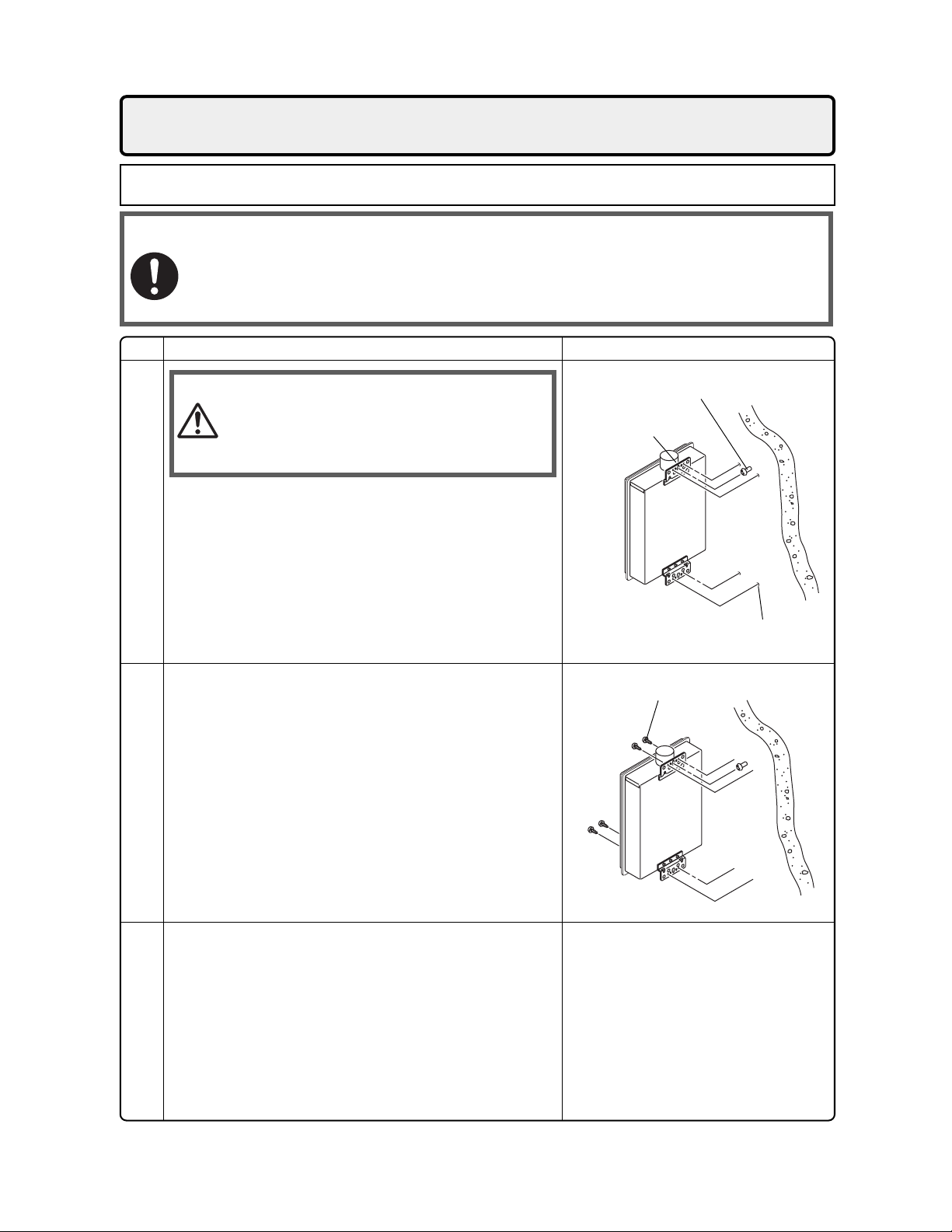
7. Installation
Securing to the wall
• The weight of the device will be applied to the wall. If the strength of the wall is not sufficient, reinforcement must be done to prevent the transfer of vibration.
• Do not drop or apply unnecessary force to the device when installing. Internal parts may
be damaged and may become highly dangerous.
• Install the unit on a vertical wall and ensure that it is level.
Item
Caution
1. Drill a single screw hole, making sure to hit a stud.
2. Insert and tighten the screw and hang the unit by
the upper wall mounting bracket.
Locating Screw Holes
3. Determine the positions for the remaining four screws
(two for the top bracket and two for the bottom), and
remove the unit.
4. Drill holes for the remaining four screws.
5. Hang the unit again by the first screw, and then
insert and tighten the remaining four screws.
6. Take waterproofing measures so that water does
not enter the building from screws mounting the
device.
Mounting
Check
• When installing with bare hands,
take caution to not inflict injury.
• Be careful not to hit electrical
wiring, gas, or water piping while
drilling holes.
Illustration
Location of Screw Hole
Mounting Bracket
(upper)
Locating Screw Holes
Tapping Screw
44
• Make sure the unit is installed securely so that it will
not fall or move due to vibrations or earthquakes.
Structure

8.
Vent Pipe Installation
(Indoor Installation Only)
Vent Piping
• Use only listed category III vent materials.
• Follow the vent pipe manufacturer's installation
instructions.
Pipe diameter 4"
No. of Elbows Max. Straight Vent Length
3 15'
2 27'
1 39'
• Make the vertical section of the exhaust vent
as short as possible.
• Maintain the same vent pipe diameter from the
heater flue to the vent termination.
Clearances
Manufacturer and Enclosed Unenclosed
Product Hor. Vert. Hor. Vert.
Noritz N-Vent 4" 3" 3"
Protech FasNSeal 4" 3" 3"
Protech FasNSeal W2 6" 4" 3" 3"
HeatFab SafTVent 6" 6" 2" 2"
Z-Flex Z-Vent 8" 4" 1" 1"
Flex-L StaR-34 8" 4" 1" 1"
These clearances are subject to change.
Refer to the UL listing for the proper clearances.
10" (sides)
15"(top)
6"(bottom)
8" (sides)
12"(top)
4"(bottom)
• The first vertical run from the top of the heater
should be no longer than 3'.
• Make sure vent pipe is gas tight and will not
leak. Use silicon sealant wherever necessary.
• Do not common vent or connect more than
one appliance to this venting system.
• The total vent length including horizontal &
vertical vent runs should be no less than 3'.
• Do not place any dangerous objects at the end
of the exhaust vent.
• Steam (smoke) or water drops may come out
from the end of the exhaust pipe. Select the
location for the end of the vent so that steam is
not visible, and the vent is not wet with dripping water.
• If snow is expected to accumulate, take care
the end of the pipe is not covered with snow or
hit by falling lumps of snow.
• Consult the vent pipe manufacturer's installation instructions for chimney connections.
Appliance Adapters
• Use the following adapters to connect the
unit to the venting system.
Manufacturer and
Product
Protech FasNSeal FSAA4
HeatFab SafTVent 9401RYPK
Z-Flex Z-Vent 2SVWA04
Flex-L Star-34 SRASPSA4
Part No.
Horizontal Vent Termination
Hanger
Elbow
Slope vent
Downwards
3'
Max.
Appliance
Adapter
Straps
Wall
Thimble
Termination
• Terminate at least 12" above
grade or above snow line.
• Terminate at least 7' above a
public walkway, 6' from the
combustion air intake of any
appliance, and 3' from any
other building opening, gas
utility meter, service regulator
etc.
• Terminate at least 3' above any
forced air inlet within 10', 4'
below, 4' horizontally from or
1' above any door, window, or
gravity air inlet into any building
per National Fuel Gas Code
ANSI Z223.1/NFPA 54.
• Slope the horizontal vent 1/4"
downwards for every 12".
• Use a condensation drain if
necessary.
45

Vertical Vent Termination
Elbow
Condensation
3'
Max.
Local Codes)
Hanger
Strap
Drain (Install
According to
Rain
Cap
Flashing
Firestop/
Support
Firestop
Roof
• Terminate at least 6' from the
combustion air intake of any
appliance, and 3' from any
other building opening, gas
utility meter, service regulator
etc.
• Enclose exterior vent systems
below the roof line to limit
condensation and protect
against mechanical failure.
• When the vent penetrates a
floor or ceiling and is not
running in a fire rated shaft, a
firestop and support is required.
• Terminate the vent system at
least 3' above, but not more
than 6' above the roof line, or
according to the vent pipe
manufacturer's instructions.
• Provide vertical support every
12' or as required by the vent
pipe manufacturer's instructions.
• Slope the horizontal vent 1/4"
downwards for every 12".
• Do not vent straight upwards.
Always have a horizontal section
of venting.
• Install a condensation drain in
the horizontal section of the
venting.
46
Appliance
Adapter

Combustion Air
• Provide two permanent openings to allow
circulation of combustion air.
• Make each opening 194 square inches if they
provide indoor air, and 100 square inches for
outdoor air.
• If the unit is installed in a mechanical closet,
provide a 24" clearance in front of the unit to
the door.
• If combustion air will be provided through a
duct, size the duct to provide 60 cubic feet of
fresh air per minute.
Supply combustion air to the units as per the National Fuel Gas Code, ANSI Z223.1.
10"
20"
20"
10"
Openings supplying indoor air
47

9.
Gas Piping
Follow the instructions from the gas supplier.
The appliance and its individual shutoff valve must be disconnected from the gas supply piping system
during any pressure testing of that system at test pressures in excess of
1
⁄2 psig (3.5 kPa).
The Appliance must be isolated from the gas supply piping system by closing its individual manual shutoff
valve during any pressure testing of the gas supply piping system at test pressures equal to or less than
psig (3.5 kPa).
The appliance and its gas connections must be leak tested before placing the appliance in operation.
The inlet gas pressure must be within the range specified. This is for the purposes of input adjustment.
In order to choose the proper size for the gas line, consult local codes or the National Fuel Gas Code ANSI
Z223.1.
Gas Pressure
Size the gas line according to total btuh demand
of the building and length from the meter or
Gas Meter
Select a gas meter capable of supplying the entire
btuh demand of all gas appliances in the building.
regulator so that the following supply pressures
are available even at maximum demand:
Natural Gas Supply Pressure
Min. 4" WC
Max. 10.5" WC
LP Gas Supply Pressure
Min. 8" WC
Max. 14" WC
Gas Connection
• Do not use piping with a diameter smaller than
the inlet diameter of the water heater.
• Gas flex lines are not recommended unless they
are rated for 194,000 btuh.
• Install a gas shutoff valve on the supply line.
• Use only approved gas piping materials.
Measuring Gas Pressure
In order to check the gas supply pressure to the unit, a
tap is provided on the gas inlet. Remove the hex head
philips screw from the tap, and connect a manometer
using a silicon tube.
1
⁄2
In order to check the gas manifold pressure, a pair of
taps are provided on the gas valve inside the unit.
The pressure can be checked either by removing the hex
head philips screw and connecting a manometer with a
silicon tube, or by removing the 1/8" NPT screw with an
allen wrench and connecting the appropriate pressure
gauge.
Sample Gas Line
Noritz N-063S or N-069M
(194,000 Btuh)
Outlet E
Section 4
5'
10'
Natural Gas
Meter
**See next page for the pipe capacity charts.
10'
Section 3 Section 2
Outlet D
Outlet C
5' 5'
5'
Gas Fireplace
(25,000 Btuh)
Clothes Dryer
(35,000 Btuh)
5'
Outlet A
Section 1
10'
Outlet B
Barbecue
(50,000 Btuh)
Gas Range Stove
(65,000 Btuh)
48
Instructions
1. Size each outlet branch starting from the furthest
using the Btuh required and the length from the
meter.
2. Size each section of the main line using the
length to the furthest outlet and the Btuh
10'
5'
required by everything after that section.
Sample Calculation
Outlet A: 45' (Use 50'), 50,000 Btuh requires 1/2"
Outlet B: 40', 65,000 Btuh requires 1/2"
Section 1: 45' (Use 50'), 115,000 Btuh requires 3/4"
Outlet C: 30', 35,000 Btuh requires 1/2"
Section 2: 45' (Use 50'), 150,000 Btuh requires 3/4"
Outlet D: 25' (Use 30'), 25,000 Btuh requires 1/2"
Section 3: 45' (Use 50'), 175,000 Btuh requires 1"
Outlet E: 25' (Use 30'), 194,000 Btuh requires 3/4"
Section 4: 45' (Use 50'), 369,000 Btuh requires 1 1/4"

Natur
al Gas
Liquified P
etroleum
Gas Line Sizing for a Noritz N-063S or N-069M
Maximum Natur
Pipe
10' 20' 30' 40' 50' 60' 70' 80' 90' 100' 125'
Size
174
1/2"
363
3/4"
684
1"
1404
1 1/4"
2103
1 1/2"
4050
2"
2 1/2"
6455
3"
11,412
16,709
3 1/2"
4"
23,277
Contact the Gas Supplier for Btu/Cubic Ft. of the Supplied Gas. 1000 BTU/Cubic Ft. is a Typical Value
Adapted from UPC 1997
al Gas
Delivery Capacity in Cubic Feet per Hour (0.60 Specific Gravity, 0.5" WC Pressure Drop)
Length in Feet
119
249
470
965
1445
2784
4437
7843
11,484
15,998
96
200
377
775
1161
2235
3563
6299
9222
12,847
82
171
323
663
993
1913
3049
5391
7893
10,995
73
152
286
588
880
1696
2703
4778
6995
9745
66
138
259
532
798
1536
2449
4329
6338
8830
61
127
239
490
734
1413
2253
3983
5831
8123
56 53 50 44
118 111 104 93
222 208 197 174
456
683
1315
2096
3705
5425
7557
428
641
1234
1966
3476
5090
7091
404
605
1165
1857
3284
4808
6698
1033
1646
2910
4261
5936
358
536
Maximum Liquified P
Pipe
10' 20' 30' 40' 50' 60' 70' 80' 90' 100' 125' 150' 200'
Size
1/2"
275
3/4"
567
1071
1"
2205
1 1/4"
3307
1 1/2"
2"
6221
** For reference only. Please consult gas pipe manufacturer for actual pipe capacities.
Maximum Capacity of Flex TracPipe in Cubic Feet per Hour of Natural Gas
Pipe
Size
10' 20' 30' 40' 50' 60' 70' 80' 90' 100' 150' 200'
206
3/4"
1"
383
1 1/4"
614
1 1/2"
1261
2"
2934
Maximum Capacity of Flex TracPipe in Thousands of Btuh Liquified Petroleum
Pipe
Size
10' 20' 30' 40' 50' 60' 70' 80' 90' 100' 150' 200'
325
3/4"
1"
605
1 1/4"
971
1 1/2"
1993
2"
4638
** For reference only. Please consult gas pipe manufacturer for actual pipe capacities.
TracPipe® is a registered trademark of Omega Flex.
189
393
732
1496
2299
4331
147
269
418
888
2078
232
425
661
1404
3285
etroleum
152
315
590
1212
1858
3465
121
218
334
723
1698
191
344
528
1143
2684
(Undiluted) Delivery Capacity in Thousands of Btuh (0.5" WC Pressure Drop)
Length in Feet
129
114
103
96
89
267
504
1039
1559
2992
105
188
284
625
1472
166
297
449
988
2327
237
217
409
834
1275
2394
Length in Feet
86
153
227
509
1203
Length in Feet
136
241
359
805
1902
196
378
771
1181
2205
80
141
209
471
1114
126
222
330
745
1761
448
913
1417
2646
R
94
168
251
559
1317
R
149
265
397
884
2082
185
346
724
1086
2047
83
173
322
677
1023
1921
75
132
194
440
1042
118
208
307
696
1647
78
162
307
630
976
1606
1811
(0.60 Specific Gravity, 0.5" WC Pressure Drop)
71
125
181
415
983
112
197
286
656
1554
67
118
171
393
933
106
186
270
621
1475
63
69
146
275
567
866
137
320
762
( 0.5" WC Pressure Drop)
143
217
506
1205
132
252
511
787
1496
55
94
87
55
112
213
440
675
1260
48
82
116
277
661
76
129
183
438
1045
Maximum Capacity for Gas Flex Connectors in Cubic Feet per Hour of Natural Gas
Pipe
Size
1/2"
3/4"
1"
1 1/4"
12" 24" 36" 48" 60" 72"
180 150
290
581
1470
Length in Inches
125
255
512
1200
106
215
442
1130
(0.60 Specific Gravity, 0.5" WC Pressure Drop)
197
397
960
Maximum Capacity for Gas Flex Connectors in Thousands of Btuh Liquified Petroleum
Pipe
Size
1/2"
3/4"
1"
1 1/4"
** For reference only. Please consult gas pipe manufacturer for actual pipe capacities.
12" 24" 36" 48" 60" 72"
288 240
465
930
2352
Length in Inches
200
409
825
1920
169
344
708
1808
149
315
638
1536
93
173
347
930
( 0.5" WC Pressure Drop)
137
278
556
1488
86
49

Ask a qualified plumber to perform the installation
10. Water Piping
This appliance suitable for potable water and space heating applications. Do not use this appliance if any part has
been underwater. Immediately call a qualified service technician to inspect the appliance and replace any part of the
control system and gas control which has been under water.
If the water heater is installed in a closed water supply system, such as one having a backflow preventer in the cold
water supply line, means shall be provided to control thermal expansion. Contact the water supplier or a local plumbing inspector on how to control this situation.
A pressure relief valve must be installed near the hot water outlet that is rated in accordance with and complying with
either The Standard for Relief Valves and Automatic Shutoff Devices for Hot Water Supply Systems, ANSI Z21.22, or
The ANSI/ASME Boiler and Pressure Vessel Code, Section IV ( Heating Boilers ). This pressure relief valve must
be capable of an hourly Btu rated temperature steam discharge of 194,000 Btuh. Multiple valves may be used. The
pressure relief capacity must not exceed 150 psig. No valve shall be placed between the relief valve and the water
heater. The relief valve must be installed such that the discharge will be conducted to a suitable place for disposal
when relief occurs. No reducing coupling or other restriction may be installed in the discharge line. The discharge line
must be installed to allow complete drainage of both the valve and the line. If this unit is installed with a separate
storage vessel, the separate vessel must have its own temperature and pressure relief valve. This valve must also
comply with The Standard for Relief Valves and Automatic Gas Shutoff Devices for Hot Water Supply Systems, ANSI
Z21.22. (in the U.S. only). A temperature relief valve is not required, but if one is used, do not install the valve with the
probe directly in the flow of water. This may cause unwarranted discharge of the valve.
Piping and components connected to the water heater shall be suitable for use with potable water.
Toxic chemicals, such as those used for boiler treatment, shall not be introduced into the potable water.
A water heater used to supply potable water may not be connected to any heating system or components previously
used with a nonpotable water heating appliance.
When water is required in one part of the system at a higher temperature than in the rest of the system, means such
as a mixing valve shall be installed to temper the water to reduce the scald hazard.
• Flush water through the pipe to clean out metal powder, sand and dirt before connecting it.
• Take appropriate heat insulation measures (e.g., wrapping with heat insulation materials, using electric heaters)
according to the climate of the region to prevent the pipe from freezing.
•
Use a union coupling or flexible pipe for connecting the pipes to reduce the force applied to the piping.
• Do not use piping with a diameter smaller than the coupling.
• When feed water pressure is too high, insert a depressurizing valve, or take
• Avoid using joints as much as possible to keep the piping simple.
• Avoid piping in which an air holdup can occur.
• If installing the unit on a roof:
• About lower-level hot water supply
If the unit is installed on a roof to supply water to the levels below, make sure that the water pressure supplied to
the unit does not drop below 29 psi. It may be necessary to install a pump system to ensure that the water pressure
is maintained at this level.
Check the pressure before putting the unit into operation.
Failure to supply the proper pressure to the unit may result in noisy operation, shorter lifetime of the unit, and may
cause the unit to shut down frequently.
of the plumbing. Observe all applicable codes.
water hammer prevention measure.
Supply water piping
• Do not use PVC piping.
• Mount a check valve and a shut off valve (near
the inlet).
• In order for the client to use the water heater
comfortably, 98.1 to 491 kPa (14 to 70 PSI) of
pressure is needed from the water supply.
Be sure to check the water pressure. If the water
pressure is low, the water heater cannot perform
to its full capability, and may become a source of
trouble for the client.
Drain piping
• Expansion water may drop from the pressure
prevention device and wet the floor. If necessary, provide drain piping or use a drain hose to
remove the water.
50
Hot water piping
• Do not use lead or PVC piping.
• The longer the piping, the greater the heat loss.
Try to make the piping as short as possible.
• Use mixing valves with low water resistance.
Use shower heads with low pressure loss.
• If necessary, use a pump or other means to ensure that the supply water pressure to the inlet
of the heater does not fall below 29 PSI when
the maximum amount of water is being demanded. Also install a pressure meter on the inlet. If this is not done, local boiling will occur inside the water heater causing abnormal sounds
and decreasing the durability of the heat exchanger.

11. Plumbing Applications
Recirculation System
Hot Water Return
Pump
(See notes for Sizing)
8-10 Gal.
Storage Tank
(To Alleviate Cold
Water Sandwich)
Backflow
Preventer
(Optional)
Pressure
Reducing
Val ve
(Optional)
Pump Control signal
((N-069M) See p. 55)
Check Valve
Aquastat
(Use Aquastat if
Unit Isn't Controlling
Pump)
Press. Gauge
(Optional)
* Size the pump to provide at least 1.58 GPM through the system at 10 Ft of Head plus
piping losses. Check the maintenance monitors on the unit to make sure the pump
is providing that much flow.
** Adjust the flow using a gate valve and verify the flow rate with the maintenance monitors.
Fixtures
* Size the pump to provide at least 1.58 GPM through the system at 10 Ft of Head plus
piping losses. Check the maintenance monitors on the unit to make sure the pump
is providing that much flow.
** Adjust the flow using a gate valve and verify the flow rate with the maintenance monitors.
Pump
(See notes for Sizing)
Air Scoop
(Optional)
Heating
Controls
Temp. &
Pressure
Relief
Val ve
Drain
Cold Water Supply
NORITZ
N-069M
N-063S
Shutoff Valve
Pressure
Relief Valve
Drain
(N-069M
Relay for
Pump
> 85 W)
(See p. 55)
Hot Water
Cold Water Supply
NORITZ
N-069M
N-063S
Shutoff Valve
Shutoff
Val ve
Check
Val ve
Expansion Tank
(Install According
to Local Codes)
Pump Control Signal
((N-069M) See p. 55)
Check Valve
Aquastat (N-063S)
(For N-069M, Use Aquastat
if Unit Isn't Controlling Pump)
(N-069M
Relay for
Pump
> 85 W)
(See p. 55)
Expansion
Tank
(Install According
to Local Codes)
Hot Water
Boiler Drain Valve
Heating System
Check
Val ve
Aquastat Wiring
Use Honeywell Aquastat
(Model L6006A or L6006C)
Pump
AC120
Neutral
Ground
Live
Hot Water Return
105
R
B
5
W
Hydronic Heat
Exchanger or
Radiant Heat
Piping
For Baseboard
Applications:
Please contact
Noritz for
compatibility.
N-069M
N-063S
Mixing Valve
Cold Water Supply
Tempered Potable Hot Water
Hot Water for Heating
For Space Heating Purposes:
If the system requires water
for space heating at a higher
temperature than for other
uses, means such as a mixing
valve shall be provided to
temper the water for the other
uses to help prevent scalding.
51

Consult a qualified electrician
12.
This appliance must be electrically grounded in accordance with local codes, or in the absence of local codes,
with the National Electrical Code, ANSI/NFPA 70. In Canada, the latest CSA C22.1 Electrical Code.
Caution: Label all wires prior to disconnection when servicing controls. Wiring errors can cause improper
and dangerous operation.
Verify proper operation after servicing.
Field wiring to be performed at time of appliance installation.
Electrical Wiring
Do not connect electrical power to the unit until all electrical wiring has been completed.
for the electrical work.
Caution
• The electrical supply required by the water
heater is 120V AC at 60 Hz.
The power consumption may be up to 125W or
higher if using optional accessories.
Use an appropriate circuit.
• Do not disconnect the power supply when not in
use. When the power is off, the freeze prevention in the water heater will not activate,
resulting in possible freezing damage.
Ground
• To prevent electrical shock, provide a ground
with resistance less than 100 . An electrician
should do this work.
• A grounding screw is provided on the back of
the junction box lid.
Do not connect the ground to the city water
or gas piping. Do not tie the ground to a telephone line.
Breaker Installation
• Mount a device which shuts off the electrical
path automatically (leakage breaker) when
electrical leakage is detected.
Do not turn on the power until the electrical wiring is finished.
This may cause electrical shock or damage to the equipment to occur.
• Do not let the power cord contact the gas piping.
Tie the redundant power cord outside the
water heater. Putting the redundant length
of cord inside the water heater may cause
electrical interference and faulty operation.
Junction Box
Junction Box Lid
Power Cord
1.Unscrew the junction box lid and open.
2.Push the power cord through the bottom of the unit.
3.Connecct the live and neutral wires to the black and
white wire in the junction box.
4.Screw the ground wire to the ground screw on the
back of the junction box lid and close junction box.
(back)
Ground
52

Remote Controller
• Applicable Model
N-069M, N-063S (option)
Remote controller
Install the remote controller according to the instructions in the Installation Guide (p. 61).
• The N-069M can be programmed so that it will default to one of four temperatures if the remote
controller is removed (176, 140, 130, 120°F). To change the default temperature, the remote controller must be initially installed, and removed after programming.
* Changing the default temperature setting:
1. Within the first ten minutes of connecting electrical power to the unit, but before pressing the
Power On/Off button, hit the up [ ] or down [ ] button on the remote controller. This will put
the unit into maintenance writer mode. If pressing either of these buttons does not put the unit
into maintenance writer mode, unplug the unit for sixty seconds and try again.
2. The maintenance monitor item number will flash on the display. (the initial item number will be “99”).
3. The up [ ] and down [ ] buttons can be used to change the maintenance writer item number.
4. Choose a temperature from the chart below and set the 14 and 15 maintenance writers according to
the chart. Pressing the Flow Meter Alarm Set button for 0.5 seconds will switch the indicated item
number from “OFF” to “ON” or “ON” to “OFF”. If the Priority lamp is flashing when an item number
is displayed, this indicates an “ON” setting for that item number, and if the Priority lamp is off, the
item number is off.
*Do not change the other item numbers. This may cause a fault in the water heater.
5. After setting the 14 and 15 item numbers for the desired temperature, press and hold the up [ ]
and down [ ] buttons together for five seconds to confirm the new settings. The remote controller will emit a tone when the settings are confirmed. If this is not done, the unit will not put the
setting changes into effect. After confirming the setting, remove the remote controller to initiate
the default temperature setting.
Note:The setting changes can be cancelled by pressing the Power On/Off button before confirming the
settings, or if the unit is left alone for ten minutes without confirming the settings. If the default
setting needs to be changed again, disconnect the electrical power to the unit, reconnect it and
follow this procedure again.
RC-7646M-2
Temp.
176°F
140°F
130°F
120°F*
Item No.
14
ON
OFF
ON
OFF
15
ON
ON
OFF
OFF
* Factory Default Setting
53

Connecting Remote Controller Cord to Unit
• Keep the remote controller cord away from the freeze prevention heaters in the unit.
• Tie the redundant cord outside the water heater. Do not put the extra length inside the equipment.
• The remote controller cord can be extended up to 300' with 18AWG wire.
• Use a Y type terminal with a resin sleeve. (Without the sleeve, the copper wire may corrode and
cause problems).
• Be sure to hand tighten when screwing to the terminal block. Power tools may cause damage to the
terminal block.
Remote controller cord
• For extensions, a 26' cord can be purchased (Part # RC-CORD26) or use 18AWG wire.
• Install according to the National Electrical Code and all applicable local codes.
1. Leave enough slack so that the remote controller
cord will not be damaged if the unit is removed from
the wall.
2. Remove the front cover of the heater (4 screws).
3. Pass the remote controller cord through the wiring
throughway and into the unit.
4. Connect the Y terminals at the end of the remote
controller cord to the terminal block.
5. Secure the remote controller cord with a clamp.
6. Replace the front cover.
Wiring
Throughways
18AWG Wire
Terminal
Block
Clamp
Changing Set Temperature (Not using the remote controller for N-063S).
1. Disconnect power to the heater.
2. Remove the front cover of the heater (4 screws).
• To set the temperature to 130°F
130°F tag
Remove the connector with 130°F tag.
• To set the temperature to 140°F
Remove the connector with 140°F tag.
3. Replace the front cover of the heater (4 screws).
4. Reconnect power to the heater.
140°F tag
54
r
o
t
c
e
n
n
o
r
o
C
t
c
F
e
°
n
0
n
3
o
1
C
F
°
0
4
1
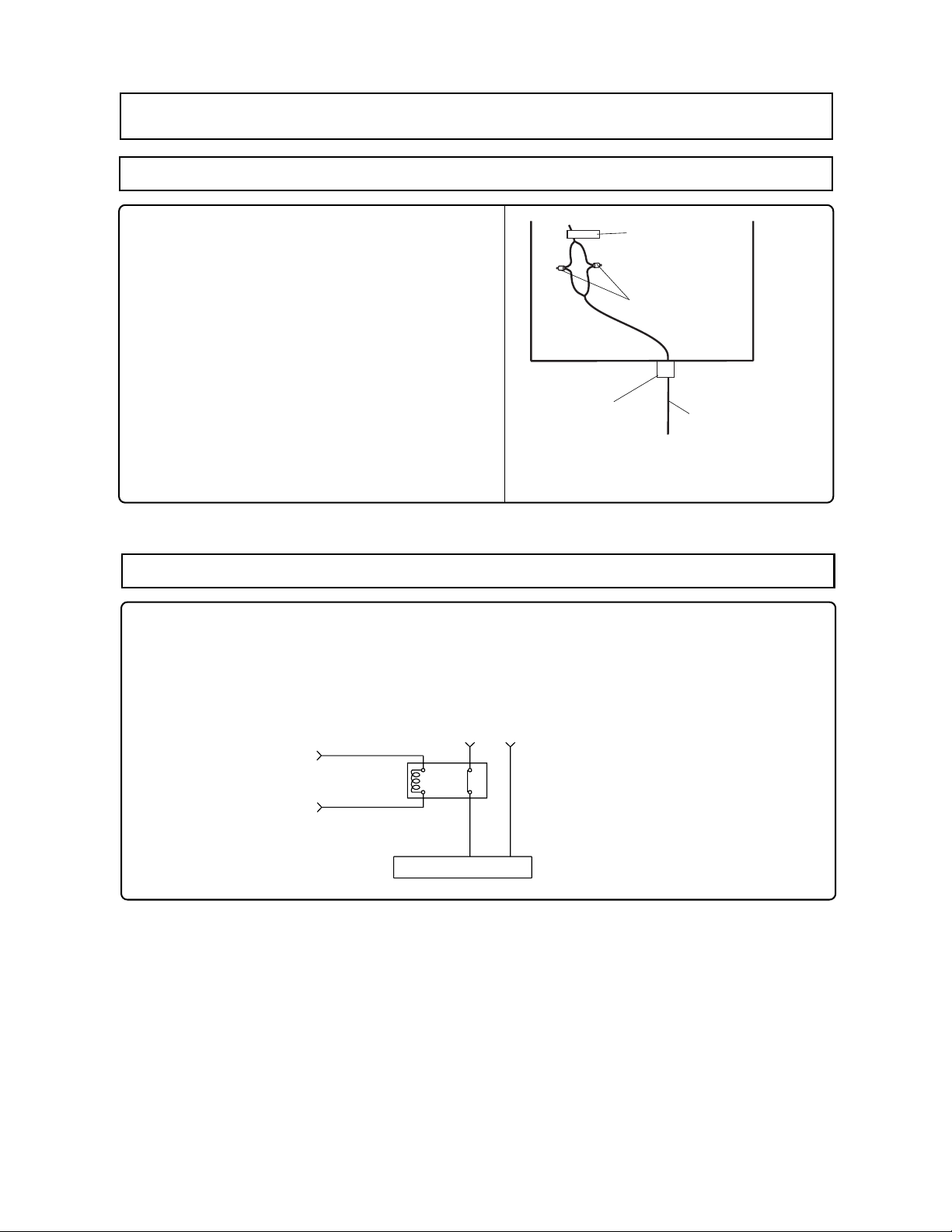
Pump Wiring
Connecting the pump control wire
* For model N-069M only. This feature is not available
when using the Quick Connect Multi System feature.
1. Leave enough slack so that the pump control
wires will stay connected if the unit is removed
from the wall.
PUMP
Pump Control
Wire Tag
2. Remove the front cover of the heater (4 screws).
3. Cut off the connector at the end of the pump
Crimping Terminal
control wires.
4. Wire the pump control wires through the wiring
throughway and connect them to the wiring inside
the pump (this will be the power supply for the pump,
do not also connect 120 V to the pump).
If a large pump is being used (greater than 85W)
use the voltage from these wires as the signal to
close a normally open relay through which 120 V will
be supplied directly from a wall circuit to the pump.
Wiring
Throughway
Supplies Power for
Circulating Pump
(Use a Relay for
Larger Pumps)
5. Replace the front cover.
Relay connection with larger pumps (>85 W)
1. Locate and prepare the pump control wires as described above.
2. Choose a suitable installation location for the relay where it will be protected from moisture.
3. Connect the pump control wires from the heater to the signal input on the relay.
4. Cut one of the electrical supply leads and wire it across the open terminals of the relay.
5. Secure all connections and replace the front cover of the heater.
Connect to Pump Control
Wires in Unit
AC120V
4
012
Circulation Pump
Relay (ex. Omron G7L2ABUBJCBAC120)
55

Periodically check the following to ensure proper
13.
• The venting system must be examined periodically by a qualified service technician to check for
any leaks or corrosion.
• The burner flame must be checked periodically for a proper blue color and consistency.
• If the flame does not appear normal, the burner may need to be cleaned.
• If the burner needs to be cleaned, it must be performed by a qualified service technician.
• Do not obstruct the flow of combustion and ventilation air.
• The pressure relief valve must be operated once a year to ensure that it is functioning properly
and there is no obstruction. Turn the power off to the unit before opening the relief valve, and
make sure that water draining out of the valve will not cause any damage.
• If the relief valve discharges periodically, it may be due to thermal expansion in a closed water
system. Contact the water supplier or a local plumbing inspector on how to correct this situation.
Do not plug the relief valve.
• See Operation Manual for further maintenance.
Warning:
14.
Maintenance
There is a scald potential if the output temperature is set too high.
Should overheating occur, or the gas supply fail to shut off, turn off the manual gas control valve to the appliance.
Do not use this appliance if any part has been under water. Immediately call a qualified service
technician to inspect the appliance and to replace any part of the control system and any gas control
which has been under water.
Periodically check and clean the filter inside the cold water inlet of the unit.
Trial Operation
operation of the water heater.
The installer should test operate the unit, explain to
the customer how to use the unit, and give the owner
this manual before leaving the installation.
• Preparation ........... (1) Open a hot water fixture to confirm that water is available, and then close
the fixture.
(2) Open the gas supply valve.
(3) Turn on the power supply. Using the remote controller, turn on the Power
On/Off button (the Operation lamp will turn on).
(1) Open a hot water fixture and confirm that the Burner On lamp comes on, and that hot water is
being produced. (If necessary, repeat until the air in the gas piping is bled out).
* White smoke may be noticed from the exhaust vent during cold weather. However, this is not a
malfunction of the unit.
* If an “11” error code appears or a Burner On indicator flashes on the remote controller, turn the
unit off and then back on again, and then open a hot water fixture again.
(2) Change the temperature setting on the remote controller and check that the water temperature changes.
• If the water heater does not operate normally, refer to “Troubleshooting” in the Operation Manual.
* After the trial operation, clean the filter in the cold water inlet.
<If installed with a quick connect multi-system>
• Turn the system power ON with the remote controller.
• Slowly open a hot water fixture and check that the units ignite sequentially. Check to see that the
hot water temperature is the same as the temperature displayed on the remote controller (*1)
* If both units do not ignite, switch which unit will ignite first by pressing the Max. or Min. Mani-fold
Pressure Set Button on the circuit board (see p. 59). (*2)
Unit A Ignites
Unit B Doesn't Ignite
Press Max. or Min. Manifold
Pressure Set Button on Unit B
Unit A Doesn't Ignite
Unit B Ignites
* If an 11 or F11 error code flashes on the remote controller, hit the Power Button on the remote
controller off and on 2 -3 times.
* If (*1) and (*2) cannot be done, the Quick Connect Cord may not be properly connected.
Check that the cord is properly connected.
56
Caution
Handling after trial operation
• If the unit will not be used immediately, close off all gas and water shutoff valves, drain all of
the water out of the unit and the plumbing system to prevent the unit and system from freezing,
and bleed the gas out of the gas line.
Freezing is not covered by the warranty.
Lighting Instructions
This water heater does not have a pilot. It is equipped with an ignition device that automatically lights
the burner.
Do not try to light the burner by hand.
1. Read the safety information in the installation manual or on the front of the water heater.
2. Turn off all electrical power to the unit.
3. Do not attempt to light the burner by hand.
4. Turn the gas control manual valve (external to the unit) clockwise to the off position.
5. Wait five minutes to clear out any gas. If the smell of gas remains, stop, and follow the instructions
on page 3 of this manual.
6. Turn the gas control manual valve counterclockwise to the on position.
7. Turn on electric power to the unit.
8. The unit will now operate whenever hot water is called for. If the unit will not operate, follow the
shutdown instructions and call a service technician.
Shutdown Instructions
1. Stop any water demand.
2. Turn off electric power.
3. Turn the gas control manual valve clockwise to the off position.
Should overheating occur, or the gas supply fail to shut off, turn off the manual control valve to the appliance.
57

15.
N-069M
Dimensions
(VIEW FROM TOP)
10.8"
10.5"
7.7"
7"
1.5"
1.8"
4.3"
HOT WATER OUTLET(3/4")
COLD WATER INLET(3/4")
UPPER WALL MOUNT BRACKETS
WIRING THROUGHWAYS
4.7"
0.4"
6.1"
1.8"
GAS INLET (3/4")
0.4"
3.2"
1.2"
6.3"
81.5
9.5"
13.3"
13.8"
13.1"
3"
FLUE COLLAR
4"
N-063S
LOWER WALL MOUNT BRACKETS
HOT WATER OUTLET(3/4")
COLD WATER INLET(3/4")
UPPER WALL MOUNT BRACKETS
4.3"
(VIEW FROM TOP)
10.5"
7.7"
7"
2.5"
10.8"
1.5"
4.7"
2.4"
4.7"
24.5"
22.3"
0.4"
0.4"
3.3"
6.1"
6.3"
1.8"
GAS INLET (3/4")
WIRING THROUGHWAYS
0.4" 9.5"
0.4"
3.2"
1.2"
3"
AIR INLET
COLD WATER INLET
WATER DRAIN VALVE
(WATER FILTER)
HOT WATER OUTLET
WATER DRAIN VALVE
23.6"
LED
BOTTOM OF CASE
1.9"
1.7"
13.3"
13.8"
13.1"
AIR INLET
BOTTOM OF CASE
1.9"
WIRING THROUGHWAYS
GAS INLET
FLUE COLLAR
4"
58
LOWER WALL MOUNT BRACKETS
4.7"
2.4"
3.3"
24.5"
0.4"
22.3"
0.4"
23.6"
AIR INLET
COLD WATER INLET
WATER DRAIN VALVE
(WATER FILTER)
HOT WATER OUTLET
WATER DRAIN VALVE
LED
BOTTOM OF CASE
1.9"
1.7"
AIR INLET
BOTTOM OF CASE
1.9"
WIRING THROUGHWAYS
GAS INLET
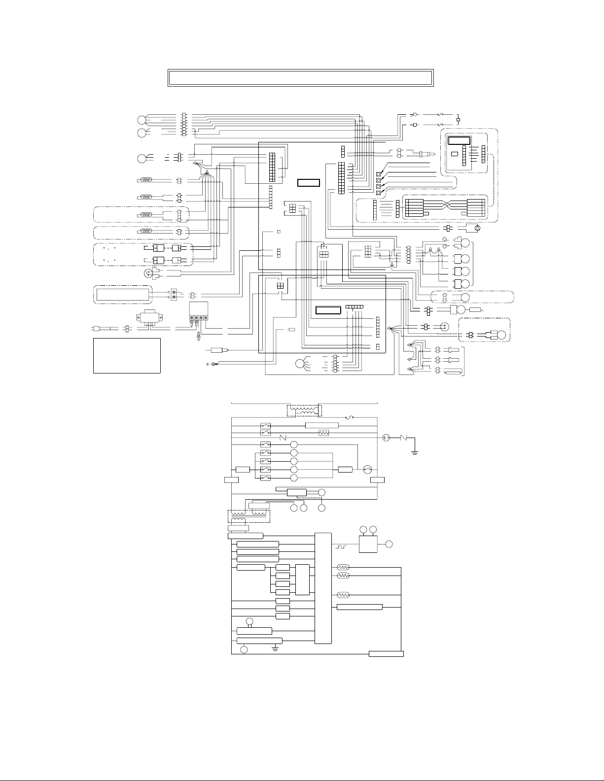
WIRING DIAGRAM (MODEL : N-069M,N-063S)
HEAT EXCHANGER
FLOW CONTROL
VALVE
HEAT EXCHANGER
FLOW SENSOR
AIR INLET
THERMISTOR
WATER INLET
THERMISTOR
WATER OUTLET
THERMISTOR
WATER OUTLET
THERMISTOR
140 F 60 C
130 F 50 C
FROST SENSING
SWITCH
<N-069M (-CA) Model Only>
REMOTE CONTROLLER
RC-7646M-2, RC-7647M
TRANSFORMER
<AC120V>
COLOR CODING
W : White
R : Red
BK : Black
V : Violet
O : Orange
SM
LS
QS
<N-069M (-CA) Model Only>
<N-063S (-CA) Model Only>
<N-063S (-CA) Model Only>
2
WBKW
1
BK
BL : Blue
GY : Gray
G : Green
BR : Brown
Y : Yellow
(VCC)
(VCC)
(Fully open)
(GND)
R
Y
(Pulse)
(VCC)
(GND)
1
2
1
2
W
W
BK
V
W
G
O
W
BR
BL
3
Y
2
1
BL BL
2
BK
1
3
2
1
4
3
2
1
2
1
1
2
1
2
BL
W
FLAME ROD
8
BK
7
V
6
W
5
G
4
O
3
W
2
BR
1
BL
Y
RR
BK
BKBK
WW
WW
WW
WW
WW
WW
R
R
BR
Y
BL
BL BL
GROUND
2
1
GROUND
BL
G
CURRENT LEAKAGE
SAFETY DEVICE
(GFCI)
BK
W
<CN59>
1
Y
3
W
5 6
7
R
9
11
13 14
15 16
17
19
8
7
6
5
4
3
2
1
<CN63>
<CN78>
<CN89>
<CN92>
2
4
BR
8
10
12
R
18
W
20
BK
W
W
1
BL
3
BL
2
1
BL
BK BK
3 4
1 2
WW
<CN100>
G
FAN MOTOR
<CN102>
3 6
OWRBK
2 5
Y
1
4
MAIN CIRCUIT
BOARD
FM
POWER CIRCUIT
BOARD
W (Vs)
BL(GND)
R (Vcc)
Y (FG)
O (Vsp)
<CN75>
GWWWBKW
2 5 1 4 3
6
<CN1>
W
BL
R
Y
O
1 2
R
3
5
7
9
11
13 14
15 16
17
19
W
21
BK
<CN38>
6
W
5
4
BL
3
R
2
Y
1
O
1
2
3
4
4
6
8
10
12
18
20
22
R
W
BL
W
O
BK
V
G
BL
BR
Y
BL
<CN27>
W
3 2 1 6 5 4
RYO
BL
<CN184>
<CN10>
BL
<CN102>
<CN103>
BURNER THRMISTOR
1
RR
2
3
WW
Manifold Gas Pressure
Increase Button
Manifold Gas Pressure
Decrease Button
Minimum Manifold Pressure Set Button
Maximum Manifold Pressure Set Button
1
1
R
R
2
2
BKBK
3
3
W
W
4
4
G
G
5
5
BL
BL
6
6
BL
BL
7
2 1
4 3
BKBKR
65
W
8 7
GY
BK
R
BL BL
GY
R
W
BK
7
O
6
5
Y
4
3
2
1
W
1
2
THERMAL FUSE
1
BL
W
THERMAL FUSE
1
BL
BL
(For Quick Connect Multi System Only)
1
R (W)
2
BK (G)
3
W (R)
4
G (BK)
5
BL
6
6
5
GY
4
BLBL
3
R
2
W
1
BK
1
BK
2
WW
3
HIGH-LIMIT SWITCH
1
WWWW
2
W
W
W
W
W
BLBL
1
BL
<N-069M (-CA) Model Only>
Other Unit in Quick Connect Multi System
MAIN CIRCUIT
BOARD
1
R
2
BK BK
3
W
184
4
G
5
BL
6
BL
7
<CN184>
Quick Connect Cord(Optional)
2
BKWWBK
1
−
BL
DU
R
+
BK
SV
11
Q1
BK
GY
SV
12
Q2
GY
W
SV
10
0
W
3
R R
SV
2
0
1
R R
BK
IG
CIRCULATION PUMP
(OPTIONAL)
W
1
W
2
W
1
W
ANTI-FROST HEATER
2
W
1
2
WWW
1
R
2
3
W
4
G
5
BL
6
BL
1
W (R)
2
(BK) G
3
(W) R
4
(G) BK
5
BL
6
BLBL
BURNING LED
GAS VALVE UNIT
<N-069M (-CA) Model Only>
WATER VALVE
FOR BY-PASS
ELECTRODE
<N-069M (-CA) Model Only>
1
2
WWW
P
HOT
DC90V
DC140V
DC15V(1)
15V POWER CIRCUIT
WATER FLOW SENSOR
WATER FLOW SERVO
FROST SENSING SWITCH
THERMAL FUSE
GAS PROPORTION VALVE
POWER CONTROL CIRCUIT
FLAME DETECTING CIRCUIT
FR FLAME ROD
10A(FUSE)
HIGH LIMIT
SWITCH
NEUTRAL
VARISTORARRESTER
GND
DC140V
DC15V(2)
RELAY 7
RELAY 8
RELAY 9
RELAY 3
RELAY 2
RELAY 4
RELAY 5
PRIMARY
VARISTOR
IG
SV0
SV1
SV2
WV
POWER
CONTROLLER
AC120V
AC100V
(N-069M
(-CA)
CIRCULATION PUMP
IGNITER
SOLENOID VALVE 0
SOLENOID VALVE 1
SOLENOID VALVE 2
WATER VALVE FOR
BY-PASS
(-CA)
ONLY)
(N-069M
FAN
BA
PRIMARY
SECONDARY
ONLY)
ANTI-FROST HEATER
COMBUTION FAN
C
DC90V
SECONDARY
B
A
INPUT AND
FAN
OUTPUT PULSE
PULSE
C
CONTROL
CIRCUIT
RELAY 2
RELAY
RELAY 3
DRIVING
CPU
CIRCUIT
RELAY 4
RELAY 5
RELAY 7
RELAY 8
RELAY 9
DU
CENTRAL
PROCESSING
UNIT
GND
WATER OUTLET THERMISTOR
WATER INLET THERMISTOR
AIR INLET THERMISTOR
BURNER SENSOR
5V POWER CIRCUIT
59

Connecting Quick Connect Cord
Caution
The wire coloring on the Quick Connect Cord will
not be the same as the wire coloring of the
connection plug inside the unit.
* The remote controller can be connected to either
unit A or B.
For Quick Connect Multi System Installation
usa a Quick Connect Cord (sold separately).
1.Red
2.Black
3.White
4.Green
5.Blue
6.Blue
1.Red
2.Black
3.White
4.Green
5.Blue
6.Blue
1.White
2.Green
3.Red
4.Black
5.Blue
6.Blue
1.Red
2.Black
3.White
4.Green
5.Blue
6.Blue
Quick Connect
Cord
Connecting the Quick Connect Cord to the two
units.
1. Turn off the power.
2. Remove the front cover of the heater (4 screws).
3. Pass the Quick Connect Cord through the wiring
throughway and into the unit.
4. Plug the connector on the Quick Connect Cord to
the receptacle inside the unit.
5. Attach the ground wire of the Quick Connect
Cord to the terminal block fixing plate.
(If the ground wire is not attached, electrical nois
may cause problems).
6. Secure the Quick Connect Cord with a clamp.
7. Replace the front cover.
AB
"Quick Connect Cord" tag
Ground wire
Connector
Connector
16A
Wiring Throughway
16A
Clamp
Coupling Cord
60

For Installers:
Remote Controller RC-7646M-2
Read this installation guide
carefully before carrying out
installation.
Installation Guide
NORITZ AMERICA CORPORATION
Note
Do not connect power to the water heater before the remote controller has been properly
installed.
Included Parts List
Part Name
Remote Controller
Wall Packing
Phillips Roundhead Wood Screw
Wall Anchor
Do not disassemble the remote controller.
Quantity
1
1
2
2
Notes on the Installation Location
• The remote should be installed in an easily
accessible location.
• Avoid installing in a place where water may
splash on the controller.
• Avoid locations where special chemical
agents (e.g., benzene, fatty and oily detergents) are used.
• Avoid outdoor installation, or installation in an
indoor location where it will be exposed to
direct sunlight.
Wall Packing
Remote Controller
Connecting Wire
Phillips Roundhead
Wood Screw
Wall Anchor
Connection of Remote Controller Cord
White Connector
Y-shaped terminals To Water heater
(two-core)
* Confirm the connection with the labels at
both ends of the remote controller cord.
• A 26' cord can be purchased separately
(Part # RC-CORD26).
• The remote controller cord can be extended up to 300 ft. by splicing the cord
and using 18 gauge wire to extend the
cord to the appropriate length.
To Remote controller
61

Installation
1. Apply Wall Packing to the rear side of the
remote controller.
2. Connect the remote controller wires to the
separate remote controller cord.
Remote
Control
Wires
Wall Packing
(take off the paper)
Remote Controller Cord
Rear Side of
Remote Controller
3. Remove the cover of the remote control,
mark the location of the screw holes, and
drill holes for the wall anchors.
4. Insert the wall anchors, screw the remote
control to the wall and replace the cover.
Wall Anchor
Phillips Roundhead
Wood Screw
62

Installing the Remote Controller Outdoor Junction Box
1. Insert the remote controller wires through the
wall pipe and secure the wall pipe to the
remote controller. Locate the remote controller
wall packing, slide it over the pipe and wires,
and apply it to the rear side of the remote.
Rear side of remote controller
Wall Packing
Secure the wall pipe
firmly into the remote
controller.
Take off the
paper.
2. Drill a 1-1/4" hole in the wall where the
remote controller will be installed.
* Do not install the remote controller in a
location that is exposed to moisture, direct
sunlight, or chemical agents. These can
damage the remote controller.
5. Slide the box nut over the remote controller
wires and screw it onto the wall pipe.
Wall Pipe
Box Nut
Remote
Controller
Wires
6. Connect the remote controller wires to the
separate remote controller cord inside the box.
Wind the excess remote controller wire on the
provided hooks as illustrated below.
(Wind the
excess wire
here.)
3. Insert the wall pipe containing the remote
controller wires through the hole.
4. Slide the junction box packing and the junction
box over the remote controller wires and wall
pipe protruding from the outside wall.
Wall packing
Take off the paper.
Wall pipe
Take out the pipe about
3/4" from the wall.
Junction Box
Box Nut
Remote
Controller
Wires
Junction Box Packing
Remote Controller
Wires
Junction Box
Remote Controller
Cord
Tie the redundant length of the remote
controller cord outside the junction box.
7. Close the junction box.
63

64

65

66
 Loading...