

Page 1
COMMERCIAL
GAS WATER HEATER
INSTALLATION, OPERATING
AND MAINTENANCE INSTRUCTION MANUAL
- Do not store or use gasoline or other
flammable vapors and liquids in the
vicinity of this or any other appliance.
- WHAT TO DO IF YOU SMELL GAS
- Do not try to light any appliance.
- Do not touch any electrical switch; do
not use any phone in your building.
- Immediately call your gas supplier from
a neighbor’s phone. Follow the gas
supplier’s instructions.
- If you cannot reach your gas supplier,
call the fire department.
- Installation and service must be
performed by a qualified installer,
service agency or the gas supplier.
WARNING: If the information in these
instructions is not followed exactly, a
fire or explosion may result causing
property damage, personal injury or
death.
READ THESE INSTRUCTIONS THOROUGHLY BEFORE STARTING
AND RETAIN THESE INSTRUCTIONS IN A SAFE LOCATION
FOR FUTURE REFERENCE
71781
Page 2

IMPORTANT
FOR THE INSTALLER AND USER OF
THIS GAS FIRED WATER HEATER
These instructions have been written for the proper
installation and safe operation of this water heater. The
installation must conform with one or more of the following as applicable:
Canadian Installation:
1. The latest edition of CAN/CGA B149.
2. Public Utility and/or local Codes
U.S. Installation:
1. Public Utility and/or local Codes
2. The latest edition of the National Fuel Gas Code
ANSI Z 223.1/NFPA 54
WARNING
This water heater must be installed strictly in accordance
with the detailed instructions enclosed and local building
codes. It must be installed with a proper temperature and
pressure relief valve which may release water in normal operation. It is also possible that connections to the water heater,
or the water heater itself may develop leaks. IT IS THERE-
FORE IMPERATIVE that the water heater be installed so that
any water is directed to an adequate drain in such a way that
it cannot damage the building, furniture, carpeting or other
property subject to water damage. THE COMPANY CANNOT
BE HELD RESPONSIBLE for damage caused by water from
the water heater, pressure relief valve or related fittings where
adequate provision to drain such water has not been made.
Closets without drains and carpeted areas are examples of
unsuitable locations for any water heater.
The warranty on this water heater is in effect only when
the heater is installed and operated in accordance with
these instructions. The manufacturer of this heater will
not be liable for any damage resulting from failure to
comply with these instructions.
IMPORTANT: Before starting the installation read
the rating plate on the heater. The gas listed must be
the same as the gas supplied to the premises. A
heater designed for Natural Gas must only be
hooked up to a natural gas supply, and likewise, a
heater designed for Propane Gas must only be
hooked up to propane.
DO NOT PROCEED UNLESS GAS TYPE OF
HEATER AND GAS SUPPLY HAVE BEEN
IDENTIFIED TO BE THE SAME.
LOCATION
Location selected should be as close to the stack or chimney
as practical and as centralized with the piping system as possible. Heater should be located in an area not subject to
freezing temperatures.
The water heater should be located so that the controls and
drain are easily accessible. The heater should be located in
an area where leakage of the tank or connections will not
result in damage to the area adjacent to the water heater or
to lower floors of the structure. When such locations cannot
be provided, it is recommended that a suitable drain pan be
installed under the heater. Such pans should be a maximum
2” deep and have a minimum length and width at least two
inches greater than the diameter of the water heater and
should be piped to an adequate drain. The pan must not
restrict combustion air flow.
Under no circumstances is the manufacturer to be held liable
for any water damage in connection with this water heater.
The water heater must be level on the floor surface.
Any enclosure surrounding the installation must allow an adequate supply of ventilation and combustion air to the water
heater. Otherwise sufficient air must be drawn from outside
the enclosure. Air may be drawn into the enclosure through an
opening. The opening shall have a free area of 1 square inch
per thousand BTU’s and be located below 18 inches and
above 6 inches as measured to the floor.
Chemical vapour corrosion can occur anywhere that flue
gases are carrying cleaning solvents, refrigerants, pool chemicals, chlorine salts. The location of the water heater should
not be near any of these chemicals.
Minimum clearances from the water heater and venting
arrangement to combustible materials are: ( See also Fig. 1
and 2).
Electronic Ignition Model -G65
3 inches from sides
3 inches from back
6 inches above vent pipe
Electronic Ignition Models - (all others)
6 inches from sides
6 inches from back
6 inches above vent pipe
Standing Pilot Models
6 inches from sides
6 inches from back
6 inches above vent pipe
Page 1
CAUTION: When this heater is installed directly on
carpeting, carpeting must be protected by a metal
or wood panel beneath the appliance, extending
beyond the full width and depth of the appliance by
at least 3 inches in any direction. If the appliance is
installed in an alcove, the entire floor must be
covered by the panel. Failure to heed this warning
may result in fire hazard.
Page 3
Page 2
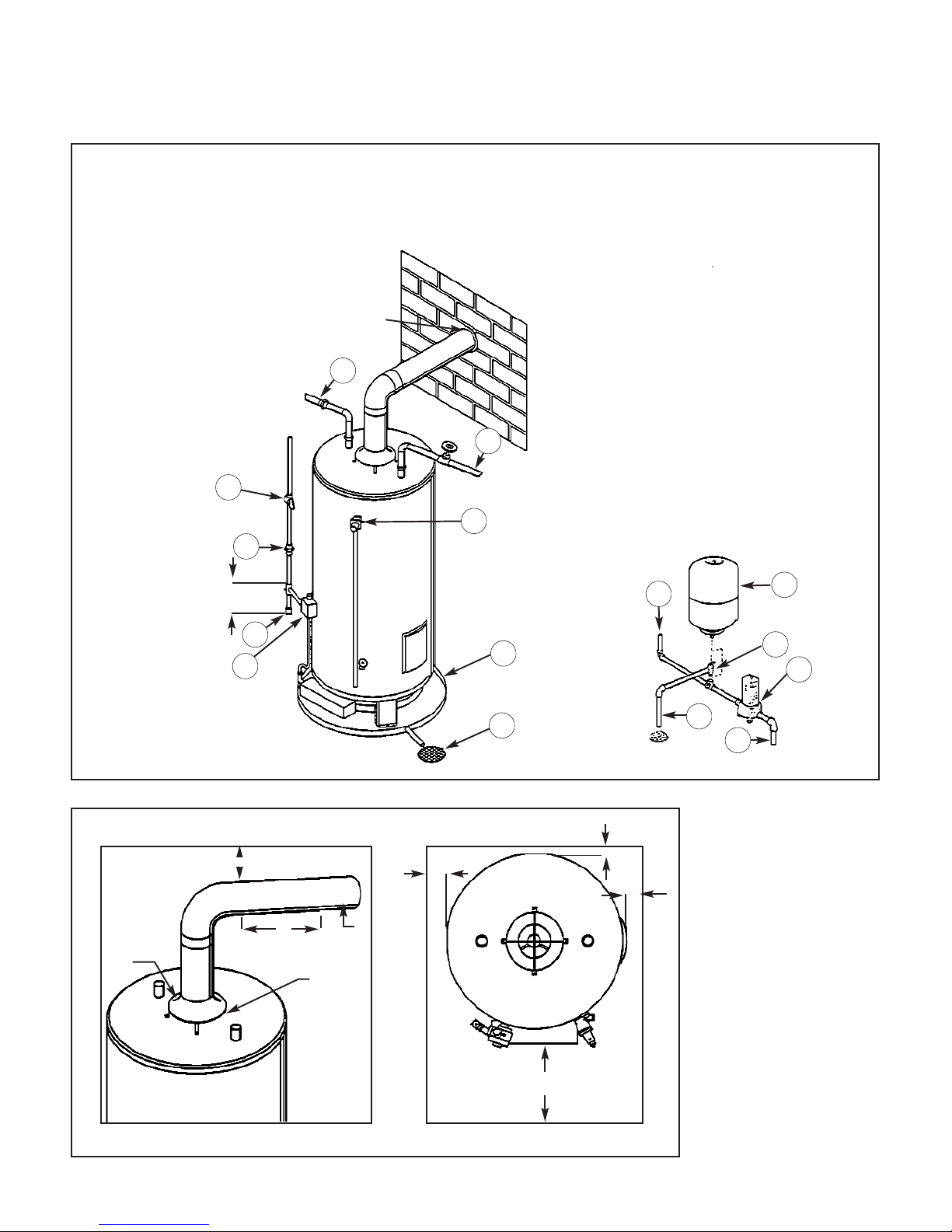
Figure 1
1. Cold water inlet
2. Hot water outlet
3. Gas supply manual shut-off valve
4. Sediment trap
5. Union - ground joint type
6. Gas control
7. Temperature & pressure relief valve
8. Floor drain
9. Drain pan (if used)
Figure 3
Location of pressure relief and/or expansion tank if a
check valve or pressure reducing valve is in the cold
water supply to the house.
Use option 1 or 2 as convenient. If pressure relief
valve is used, select one with a setting 25 psi. below
rating at tank.
10. Water supply to meter
11. Water supply to home
12. Water meter with backflow preventer
13. Overflow
14. Pressure relief valve
15. Expansion tank
seal tightly
11
15
14
12
13
10
8
9
7
1
2
3
5
4
6
6”
Figure 2
12
6
1/4
SHEET METAL
SCREWS
3”
3”
3”
MAINTAIN 26”
FOR ACCESS
Option 1
Option 2
DRAFT
HOOD
Page 4

WATER PIPING
Pipes and fittings should be installed in compliance with the
installation drawing. Makes sure the dip tube is in the cold
water fitting and water connections are made correctly.
Have the installer show you where the water shut-off valve for
the water heater has been installed so that you know where
and how to shut the water off. It is recommended that such a
valve be located in close proximity to the cold water inlet of
the water heater. (See installation drawing, Figure 3).
Connect the cold water supply to the fitting marked “COLD”
the hot water outlet to the fitting marked “HOT”. Do not apply
heat to either of these fittings. It is imperative that no heat
be applied to these fittings as they contain a non-metallic
tube. When marking these connections, always use a good
grade of pipe joint compound and be certain that all fittings
are drawn up tight.
After piping has been installed, allow tank to fill up with water
and check connections for leaks. To ensure complete filling of
the tank, allow air to exit by opening the nearest hot water
faucet until a constant flow of water is obtained.
Check your area for water hardness. Hard water conditions
can shorten tank life or cause excessive maintenance. When
hard water conditions exist water softening is the best answer
to protect both the water heater and the appliances using hot
water.
Pressure Build-up in a Water System
During the heating cycle of the water heater, the water
expands, creating a pressure build-up in the water system. The water supply meter may contain a check valve or
back-flow preventer, creating a closed water system. A
method of controlling thermal expansion would then be
required. Contact the water supplier or local plumbing
inspector for instructions to control the situation.
A temperature and pressure relief valve must be installed
on the water heater (150 p.s.i maximum pressure setting.
See Temperature and Pressure Relief Valve, below.)
Should the relief valve discharge water, a potentially
dangerous situation may be indicated and must be investigated. Have the operation of the heater checked by a
qualified service person.
Temperature and Pressure Relief Valve
For protection against excessive pressure and/or
temperatures, a temperature and pressure relief valve must
be installed in the opening marked “T&P VALVE” - a design
certified by a nationally recognized testing laboratory that
maintains periodic inspection of production of listed equipment
or materials, as meeting the requirements of Relief Valves and
Automatic Gas Shutoff Devices for Hot Water Supply
Systems, ANSI Z 21.22 - latest edition. Pressure rating of the
valve must not exceed the working pressure shown on the rating plate of the water heater. The discharge capacity must
be equal to or greater than the input to the water heater.
Water heaters intended to be shipped to Canadian
destinations may have the temperature and pressure relief
valve factory installed. Any replacement valve must meet the
latest edition of CAN 1-4.4, the Standard for “Temperature,
Pressure, Temperature and Pressure Relief Valves and
Vacuum Relief Valves.”
Relief valve piping must terminate 6 inches above a floor
drain or external to the building. Do not thread, cap or plug the
end of this discharge line. Be certain that no contact is made
with any live electrical part. Do not connect discharge line
directly to drain. See figure 3. To prevent bodily injury, hazard
to life or damage to property, the relief valve must be allowed
to discharge water in the event of excessive temperature or
pressure developing in the water heater. The function of the
temperature and pressure relief valve is to discharge water in
quantities should circumstances demand. If the discharge
pipe is not directed to a drain as shown in Figure 3 or other
suitable means, the water flow may cause property damage.
The discharge line:
1. Shall not be reduced by a coupling or any other restriction;
2. Must not be plugged, or blocked;
3. Must be of material capable of withstanding 210
o
F,
without distortion;
4. Must be installed so as to allow complete drainage of
both the temperature and pressure relief valve and discharge lines;
5. Must terminate at an adequate drain; and
6. Must not have any valve installed between the relief
valve and the water heater.
Page 3
Failure to install and maintain a new,
properly listed temperature and
pressure relief valve will release the
manufacturer from any claims which may result
from excessive temperature or water pressure.
WARNING:
Do not attempt to operate this water heater
with the cold water inlet valve close.
Manually operate temperature and pressure
relief valve at least once a year. Standing
clear of the outlet, (discharge water will be
hot), lift and release the lever handle on the
temperature and pressure relief valve to
make sure the valve operates freely.
NEVER OPERATE THE HEATER IF IT IS NOT
COMPLETELY FILLED WITH WATER. TO
MAKE SURE THE HEATER IS FILLED, OPEN
THE HOT FAUCET OF TAP UNTIL A FULL
FLOW OF WATER IS VISIBLE WITH NO AIR
ESCAPING.
Page 5
The installation of this appliance must conform to
applicable local codes and local authorities having
jurisdictions.
Install the gas piping as indicated in Figure 2. Use only new
pipe and fittings with sound, clean-cut pipe thread. Sealing
compound must conform to the applicable code for pipe
sealing compound approved for use with natural gas and
propane. It is important to have a readily accessible manual shut-off valve in the gas line supplying the heater, close
to the heater. A drip leg must be installed ahead of the gas
control valve to help trap sediments and foreign material.
A ground-joint union must be installed ahead of the gas
valve to permit easy removal of the unit.
Pipe sizing and the number of fittings used must conform to
the National Fuel Gas Code, Natural Gas Installation Code
B.149.1 or Propane Gas Installation Code B149.2.
The appliance and its gas connection must be leak tested
before placing the appliance in operation.
All leak testing must be done with soapy water solution.
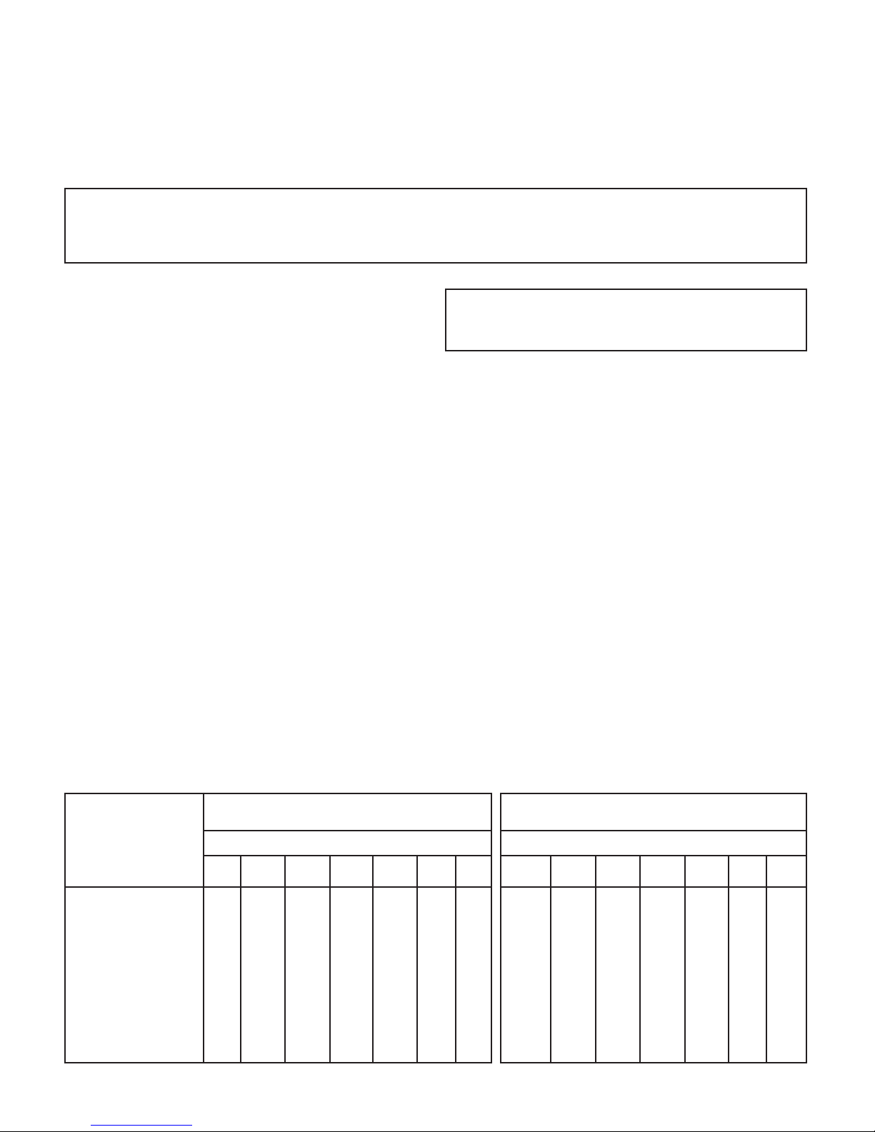
Table I
Gas Supply Line Sizes (Inches)
(Based on pressure drop of 0.3 inches water column)
Correct Gas Pipe Size for Heaters Operating on:
The maximum inlet gas pressure to the appliance must not
exceed the gas pressure marked on the rating plate: 10.5”
W.C. for natural gas and 13” W.C. for propane gas.
The minimum supply pressure for the purpose of input
adjustment is 1” above manifold pressure. The appliance
and its individual shut-off valve must be disconnected from
the gas supply piping system during any pressure testing of
that system at test pressures in excess of 1/2 psig (3.5 kPa)
The appliance must be isolated from the gas supply piping
system by closing its individual manual shut-off valve during
any pressure testing of the gas supply piping system at
least pressures equal to or, less then 1/2 psig(3.5kPA)
The input rating of the appliance should be checked against
the actual input and the manifold pressure adjusted to give
the correct input. In no case should the input exceed the
rated input. Overfiring and damage to the appliance will
result. High altitude installations require an input check
since overfiring is more likely.
Page 4
IMPORTANT: GAS SUPPLY
HAVE YOU CHECKED THE GAS SUPPLIED AND COMPARED IT WITH THE GAS MARKED
ON THE RATING PLATE? SEE ALSO WARNING ON PAGE 1.
GAS CONNECTIONS
NEVER USE A MATCH OR OPEN FLAME
TO TEST FOR GAS LEAKS.
A FIRE OR EXPLOSION COULD RESULT.
RATE
BTU
INPUT
NATURAL GAS
Specific gravity 0.6
DISTANCE TO METER IN FEET
PROPANE
Specific gravity 1.53
DISTANCE TO METER IN FEET
30
1/2
3/4
3/4
1
1
1-1/4
1-1/4
1-1/4
1-1/2
1-1/2
60
3/4
1
1
1-1/4
1-1/4
1-1/4
1-1/2
1-1/2
2
2
90
3/4
1
1
1-1/4
1-1/4
1-1/4
1-1/2
2
2
2
120
3/4
1
1-1/4
1-1/4
1-1/4
1-1/2
1-1/2
2
2
2
150
1
1-1/4
1-1/4
1-1/4
1-1/4
1-1/2
2
2
2
3
180
1
1-1/4
1-1/4
1-1/4
1-1/2
1-1/2
2
2
2
3
210
1
1-1/4
1-1/4
1-1/4
1-1/2
1-1/2
2
2
2
3
58,000
95,000
150,000
200,000
250,000
300,000
400,000
500,000
600,000
750,000
30
1/2
3/4
3/4
3/4
1
1
1-1/4
1-1/4
1-1/4
1-1/4
60
1/2
3/4
3/4
1
1
1-1/4
1-1/4
1-1/4
1-1/2
1-1/2
90
1/2
3/4
1
1
1
1-1/4
1-1/4
1-1/4
1-1/2
2
120
1/2
1
1
1-1/4
1-1/4
1-1/4
1-1/4
1-1/2
1-1/2
2
150
1/2
1
1
1-1/4
1-1/4
1-1/4
1-1/2
1-1/2
2
2
180
1/2
1
1
1-1/4
1-1/4
1-1/4
1-1/2
1-1/2
2
2
210
1/2
1
1-1/4
1-1/4
1-1/4
1-1/4
1-1/2
1-1/2
2
2
Page 6
INPUT
BTU/HR.
58,000
90,000
135,000
160,000
180,000
200,000
225,000
270,000
315,000
360,000
NATURAL GAS
1000 BTU/CU. FT.
62 SEC.
40 SEC.
27 SEC.
22 SEC.
20 SEC.
18 SEC.
16 SEC.
13 SEC.
12 SEC.
10 SEC.
PROPANE
2500 BTU/CU. FT.
155 SEC.
100 SEC.
67 SEC.
56 SEC.
50 SEC.
45 SEC.
40 SEC.
33 SEC.
29 SEC.
25 SEC.
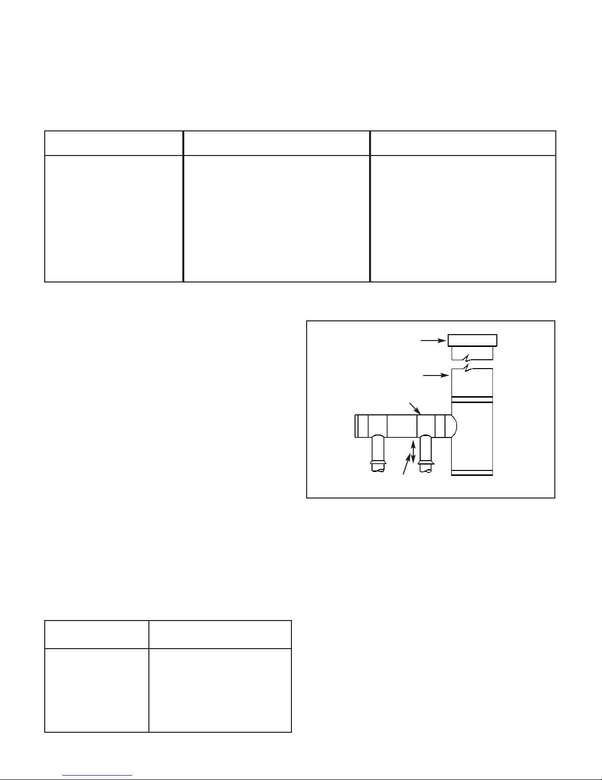
Table II
No. of seconds required to consume 1 cu. ft. of gas.
VENTING
To carry off the products of combustion, a vent pipe must be
attached to the drafthood of the heater and connected to a
chimney vent of adequate height and area. Venting
connections should be made in accordance with all codes
and ordinances which apply.
Ensure that the vent pipe is securely fastened to the draft hood
and that the draft hood is properly attached to the heater. For a
single heater installation the vent pipe must be sized no smaller than the flue size of the heater. Horizontal runs of vent pipe
should be installed with a rise of at least 1/4” per foot of length.
The vertical connector rise of vent pipe above the draft hood,
before any fittings, should be as great as possible.
When more then one heater is installed and the vents are
combined, the area of the horizontal manifold and common
vent should be at least equal to the area of the largest single
vent, plus 50% of the area of all other vents joining it (see
Vent Size Chart below) (For example, to combine two 6” vents
with a 5” vent, the area of the combined vent would be equal
to 28 + 28/2+20/2 equals 52 square inches - use a minimum
9 inch common vent and manifold). Units with larger inputs
must be vented below others. When using a common vent
connector, it shall be at the highest practical level.
The chimney vent must be extended at least two feet higher
than any obstruction located within 10 feet.
Where a back draft exists, the cause must be determined and
corrected. A flue cap on the chimney vent may correct the situation. However, if the back draft cannot be corrected, if long
horizontal vent pipe runs are necessary, or if a suitable flue
cannot be obtained, a mechanical exhaust may be required to
ensure proper venting and combustion.
Some local codes prohibit connecting a gas heater to a flue or
chimney with coal or oil fired equipment. Therefore, these
connections should be avoided. However, where a separate
chimney is not available, the flue pipe from the water heater
should enter the common flue or chimney at a point ABOVE
the flue pipe from the coal or oil fired equipment.
Improper venting may result in poor combustion, sooting and
serious damage to the heater.
DIA.
IN.
5
6
7
8
9
AREA
SQ. IN.
20
28
38
50
64
DIA.
IN.
10
12
14
16
AREA
SQ. IN.
79
113
154
201
VENT TOP
OR CAP
COMMON
CHIMNEY VENT
MANIFOLD
CONNECTOR
RISE
VENT
CONNECTOR
TEE
CAPPED
Page 5
Page 7
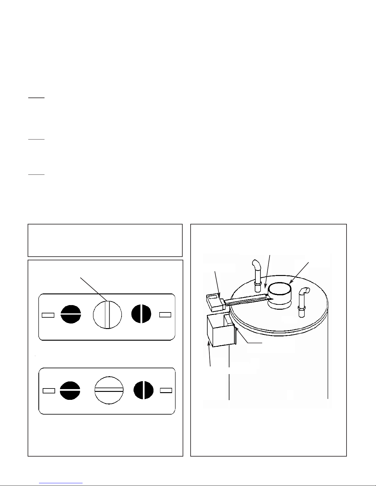
FLUE DAMPER
Flue Damper Installation
For Models equipped with a flue damper, the following instructions
must be followed. It is recommended to leave a minimum 24”
clearance from the actuator side of the flue damper for service
access.
S
tep 1:
Place flue damper on top pan into flue collector. The rail support
must be screwed to the top pan. The three pre-drilled holes on the
casing top must align with the three holes on the rail support. The
rail support must fit flush with the casing top.
S
tep 2:
Install the draft hood which is supplied with the heater in the carton
to the heater top. Fasten the draft hood with the four sheet metal
screws supplied.
S
tep 3:
Remove junction box cover plugs. Remove flue damper cover. The
wiring harness provided plugs into the four plug female molex connector (use strain relief connector provided). Molex plugs mate
together one way only.
To manually set the damper in the open position, see diagram below.
Flue Damper Venting
The vent pipe (flue pipe) must be installed without restriction
or reduction in size. Slope the horizontal run upwards to the
chimney at least 1/4” per foot. Fasten all joints with sheet
metal screws. (See Figure 4)
Venting must be inspected every three months for blockage
and problems due to age of the vent piping.
Damper Position Indicator
The damper position indicator can be found on the flue collar
of the flue damper. (See Figure 4).
Heater Wiring
Follow local codes for all electrical work. To reduce risk of
shock or possible electrocution, the heater must be electrically grounded in accordance with local codes or, in the absence
of local codes, with the National Electrical Code, ANSI /
NFPA 70.
If any of the original wiring must be replaced use only type
105
o
C thermoplastic or equivalent.
NOTE: THE FLUE DAMPER MUST BE IN THE OPEN
POSITION WHEN APPLIANCE, PILOT AND OR MAIN
BURNERS ARE ON. THIS SHOULD BE CHECKED BY
THE INSTALLER BEFORE LEAVING.
DAMPER SHAFT POSITION
“OPEN” POSITION
“CLOSED” POSITION
CLOSED
OPEN
CLOSED
OPEN
Figure 4
COLD
HOT
MOUNTING SCREWS (4)
DAMPER
POSITION
INDICATOR
JUNCTION BOX
JUNCTION BOX COVER
VENT DAMPER
Page 6
Page 8

Connection Diagram
Appliance in Standby Condition
The motor is energized during appliance thermostat “off” cycle.
The flue damper is the “closed” position.
Circuit diagram is as shown.
SL VENT DAMPER
128 VAC
24 V
R1 (N.C.)
R2 (N.O.)
SS2 (N.O.)
E.S. (N.O.)
(N.O.)
SS1
E.C.O.
TH.ST
VALV E
GNO
2
M
1
3
4
Schematic - Valve and Ignition Module
VALVE AND IGNITION MODULE
SL VENT DAMPER
R2 (N.O.)
SS2 (N.O.)
E.S. (N.O.)
128V
NEUTRAL
H
24V
E.C.O
TH.ST
(N.O.)
R1 (N.C.)
HV PV
N.S.I.
ONO
N.S.I.
RELAY
DRIVE
PLANE
SENSOR
TRIAC
24 DC
POWER
SUPPLY
DUAL VALVE
OUT
PILOT
ONO
HSI
FLAME SENSING
PILOT BURNER
BURNER
2
M
3
4
X
X
Page 7
Page 9
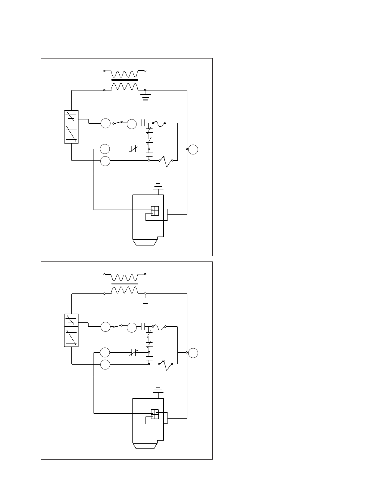
20 VAC
24 VAC
E.C.O.
TH.
R1 (N.C.)
FUSE
R2 (N.O.)
SS2 (N.O.)
E.S.(N.O.)
VENT DAMPER
VALV E
GND.
2
M
3
4
1
20 VAC
24 VAC
E.C.O.
TH.
R1 (N.C.)
FUSE
R2 (N.O.)
SS2 (N.O.)
E.S.(N.O.)
VENT DAMPER
VALV E
GND.
2
M
3
4
1
On Appliance Call for Heat - Stage 1
The thermostat contacts close and they relay coil
is energized.
Relay contacts R1 (N.C.) now open, and the
motor is de-energized.
Relay contacts R2 (N.O.) now close.
On Appliance Call for Heat - Stage 2
The flue damper spring begins to operate to
return the damper blade to the open position to
permit operation of the appliance.
During this damper blade movement, the
mechanically operated switches (SS1, SS2, and
E.S.) change their operating positions, which
results in the following:
When the switch SS2 opens, it causes the SS1
switch to close. When the damper blade reaches
the full open position, the switch contacts ES
close and the electrical circuit energizes the ignition system.
Page 8
Page 10

ELECTRONIC IGNITION MODELS:
ROBERTSHAW IGNITION MODULE AND VALVE
SCHEMA
TIC DIAGRAM
L1 (HOT)
120 VAC
L2 (NEU.) L3 (GND)
24 VOLT TRANSFORMER
MOTOR
SERV.
SWITCH
R1(N.C.)
NORMAL
POSITION
S.S.1
(N.O.)
ECO
TH.ST
2
3
4
1
DAMPER
DRIVE
FLAIR-SL
QUICK
CONNECT
RELAY
COIL
CHASSIS
GROUND
GAS VALVE
TR TH
ROBERTSHAW CONTROL MODULE
SP745
MV
TH
PV/MV
TR
GND
PV
ING
HIGH VOLTAGE
LEAD
SPARK
ELECTRODE
NOTE: IF ANY OF THE ORIGINAL WIRE AS SUPPLIED MUST BE
REPLACED. USE ONLY TYPE 105
O
C THERMOPLASTIC OR EQUIVALENT.
EXCEPT THE SPARK IGNITION CABLE WHICH MUST BE HIGH VOLTAGE 450
O
C
FACTORY INSTALLED WIRES
BY INSTALLER
Page 9
R2 (N.O)
S.S.2 (N.C)
E.S. (N.O.)
Page 11
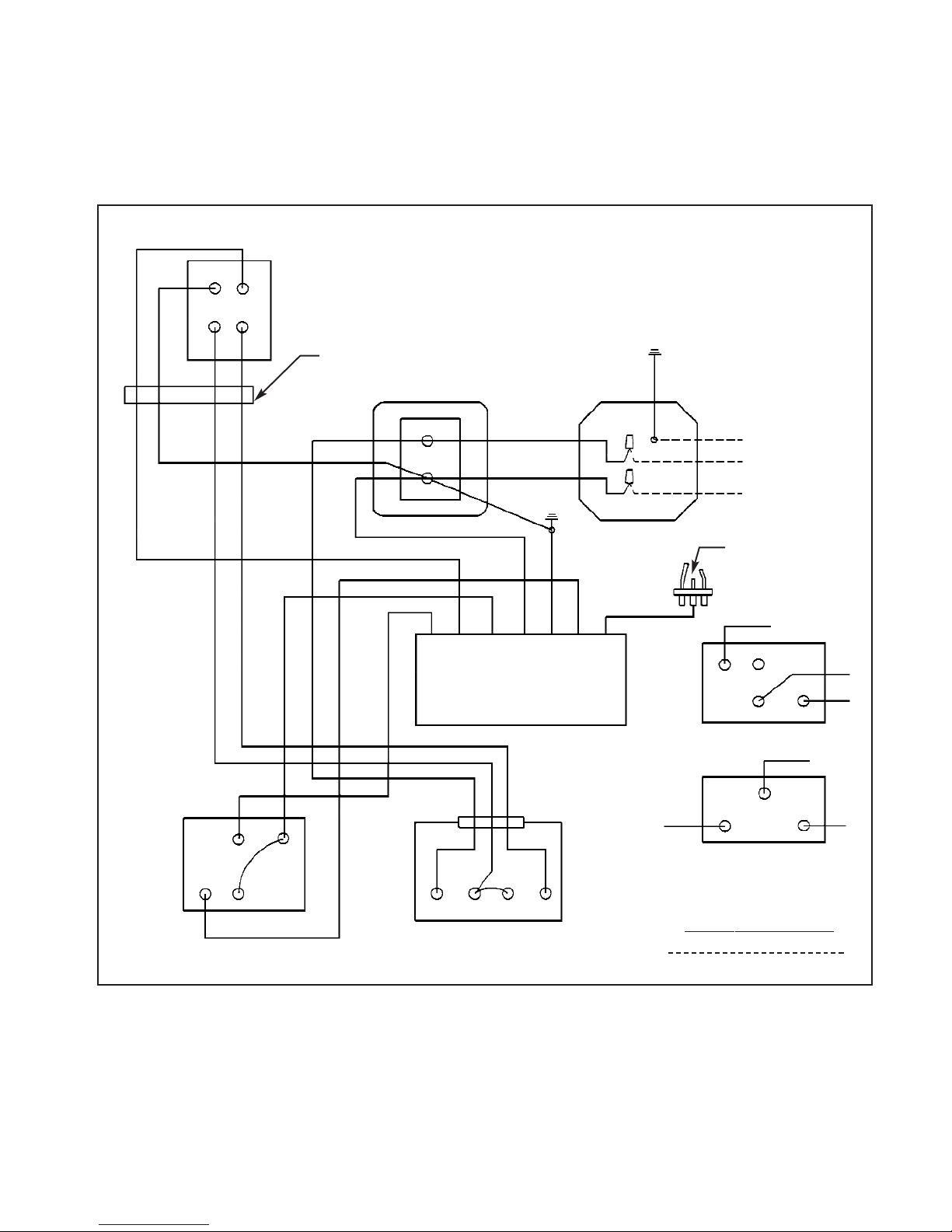
Page 10
ROBERTSHAW CONTROL MODULE
SP745
MV
TH
PV/MV
TR
GND
PV
ING
ROBERTSHAW VALVE
TEMPERATURE CONTROL
TH TR
D
D
O
ECO
TH
O
ST
YELLOW
MV
TH
TR
TH
TR
PV
PV/MV
WHITE RODGERS VALVE
PV
PV
TH
TR
MV
PV/MV
MV
SPARK
ELECTRODE
L3 (GND.)
L1 120 VAC.
L2 NEUTRAL
JUNCTION BOX
24 V TRANS
YELLOW
QUICK CONNECT
1
3
2
4
FLAIR
DAMPER
DRIVE
CONNECTION DIAGRAM
FACTORY INSTALLED WIRES
BY INSTALLER
ALL WIRES ARE BLUE, WITH LABELING.
EXCEPT WHERE OTHERWISE SHOWN.
HONEYWELL VALVE
Page 12
Page11
AIR SUPPLY
Ensure that adequate ventilation is available to supply
make-up air for proper combustion. Openings sufficient to
provide one square inch of free area for each 1,000 BTU/hr.
input rating of all appliances must be provided for this
purpose. Where heaters are installed in a confined space,
two openings - one near the top of the enclosure and one
near the bottom each having a free area of one square inch
for each 1,000 BTU/hr. input - shall be provided. Refer to
standard CAN 1-B.149-1 or .2 or local codes for complete
ventilation and combustion air requirements.
If an exhaust fan is in the same room as a heater, adequate
air openings must be provided in the walls, otherwise, air
may be drawn into the room through the chimney or flue
causing poor combustion.
MECHANICAL POWER VENTING OPTION
Power venting is an option on your water heater. A power
venter kit is available for every model. Please consult with
the company for more details.
FOR YOUR SAFETY
READ BEFORE LIGHTING
IMPORTANT
STANDING PILOT INSTRUCTIONS
A. This appliance has a pilot which must be lighted by hand.
When lighting the pilot, follow these instructions exactly.
B. BEFORE LIGHTING smell all around the appliance area
for gas. Be sure to smell next to the floor because some
gas is heavier than air and will settle to the floor.
What To Do if You Smell Gas
- Do not try to light any appliance.
- If you cannot reach your gas supplier, call
the fire department.
- Do not touch any electric switch; do not use
any phone in your building.
- Immediately call your gas supplier from a
neighbour’s phone. Follow the gas supplier’s
instructions.
C. Use only your hand to push in or turn the gas control knob.
Never use tools. If the knob will not push in or turn by
hand, don’t try to repair it, call a qualified service
technician. Force or attempted repair may result in a fire or
explosion.
D. Do not use this appliance if any part has been under water.
Immediately call a qualified service technician to inspect the
appliance and to replace any part of the control system and
any gas control which has been under water.
INSTALLATION CHECK LIST
check here
1. Has the gas piping been leak tested?
2. Is there at least a 3 inch clearance
between the water heater and
combustible material, 6” at the flue
and sufficient access for servicing at
the front?
3. Have you taken steps to prevent
water damage in case of leaks?
4. Does the area around the heater
have adequate ventilation?
5. Is the dip tube installed in the cold
water inlet connection where
applicable?
6. Is the water heater completely filled
with water?
7. Does the gas piping conform with the
recommendations for your Gas Utility
Company?
8. Is the draft hood and vent pipe
installed properly?
9. Is the draft hood relief opening
unobstructed?
10. Is the temperature and pressure relief
valve installed?
11. Is the drain pipe from the T&P valve
unobstructed?
WARNING: TO AVOID POSSIBLE INJURY, FIRE
AND EXPLOSION, READ THESE PRECAUTIONS
BEFORE ATTEMPTING TO LIGHT OR
RELIGHT THE PILOT.
WARNING:
If you do not follow these instructions exactly
, a fire
or explosion may result, causing property damage,
personal injury or loss of life.
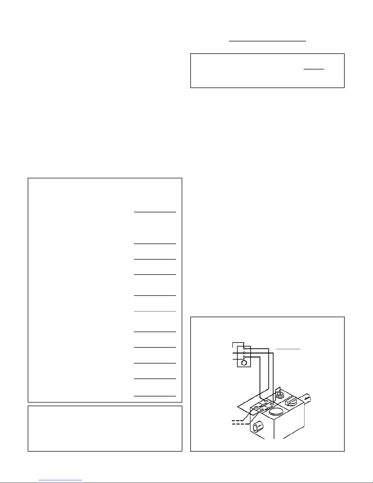
WIRING DIAGRAM, THERMOSTAT TO MAIN GAS VALVE
ECO.
THERM
BLACK
WHITE
RED
IMPORTANT
DO NOT REMOVE
THERMOSTAT FROM
THE WELL WHEN
INSTALLING.
THERMOSTAT WITH
BUILT IN ENERGY
CUT-OFF
TO POWERPILE
GENERATOR
OUTLET
MAIN GAS VALVE
YS-S90 A.C
INLET
80239
Page 13
Page 12
LIGHTING INSTRUCTIONS
WHITE - RODGERS GAS CONTROLS
1. STOP! Read the safety information at the head of this
section.
2. Set the thermostat to lowest setting. (Rotate dial
clock-wise).
3. Depress gas control slightly and turn clock-wise to
“OFF”. If knob is in “ON” position, turn clock-wise to
“PILOT” then depress knob slightly and turn
clock-wise to “OFF”.
4. Wait five (5) minutes to clear out any gas. If you smell
gas, STOP! Follow “B” in the safety information at the
head of this section. If you don’t smell gas, go to the next
step.
5. Remove burner access cover located below the gas
control unit.
6. Find pilot - follow small metal tubes from gas control. The
pilot is located between the two centre burners.
7. Turn knob on gas control knob counter-clock-wise
to “PILOT”
8. Depress control knob all the way and hold in. Immediately
light the pilot with a match. Continue to hold the control
knob down for about 1 minute after the pilot is lit. Release
knob and it will pop back up. Pilot should remain lit. If it
goes out, repeat steps 3,4,7 and 8.
If knob does not pop up when released, turn clock-wise to
“OFF”, stop and immediately call your service
technician or gas supplier.
If the pilot will not stay lit after several tries, turn the gas
control knob “OFF” and call your service technician or gas
supplier.
9. Replace burner access cover.
10.Turn gas control knob counter-clock-wise to “ON”
position.
Set the thermostat to desired setting clock-wise.
To Turn Off Gas To Appliance
1. Set the thermostat to lowest setting.
2. Turn the gas control knob clock-wise to
“PILOT”
3. Depress gas control knob slightly and turn clock-wise to
“OFF”. Do not use tools or excessive force.
BEFORE LIGHTING, SNIFF AT FLOOR LEVEL. IF
YOU SMELL GAS, FOLLOW THESE RULES:
1. Get all people out of the building.
2. DO NOT light matches.
3. DO NOT TOUCH electrical switches (on or off)
4. DO NOT use an electric fan to remove gas from
area.
5. SHUT OFF GAS at the LP tank outside of the
building.
6. IMMEDIATELY call the LP Gas Company or the fire
department from a neighbour’s telephone. Ask for
instructions, before hanging up, give your name,
address and telephone number.
7. DO NOT go back into the building. If help is coming, wait
for it outside of the building.
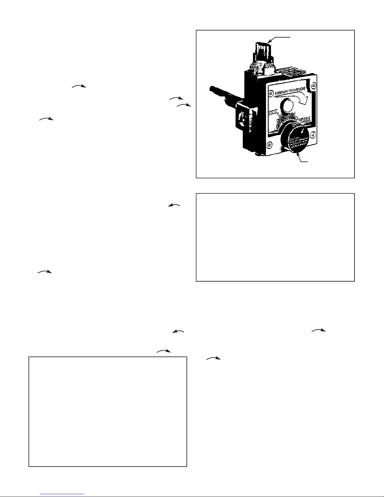
GAS CONTROL KNOB
(OFF-PILOT-ON)
TEMPERATURE
DIAL
WARNING:
Should overheating occur, or the gas supply
fail to shut off, turn the manual gas control to the
appliance to “OFF”.
WARNING:
HOTTER WATER INCREASES THE RISK
OF SCALD
Page 14

Page 13
LIGHTING INSTRUCTIONS
FOR
ELECTRONIC IGNITION GAS MODELS
FOR YOUR SAFETY READ BEFORE LIGHTING
A. This appliance is equipped with an ignition device
which automatically lights the pilot, DO NOT TRY TO
LIGHT MANUALLY.
B. BEFORE LIGHTING, smell around the appliance area
for gas. Be sure to smell next to the floor because
some gas is heavier than air and will settle on the floor.
What Do You Do If You Smell Gas?
- Do not try to light any appliance.
- Do not touch any electrical switch: do not use any phone
in the building.
- Immediately call your gas supplier from a neighbour’s
phone. Follow the gas supplier’s instructions.
- If you cannot reach your gas supplier, call the fire
department.
C. Use only your hand to turn the gas control knob. Never
use tools. If the knob will not turn by hand, don’t try to
repair it, call a qualified service technician. Forcing or
attempting to repair may result in fire or explosion.
D. Do not use this appliance if any part has been under
water. Immediately call a qualified service technician to
inspect the appliance and to replace any part of the
control system, and any gas control which has been
under water.
Operating Instructions
1. Stop! Read the safety information above.
2. Turn off all electric power to appliance.
3. Remove thermostat access door.
4. Set thermostat to lowest setting.
5. This appliance is equipped with an ignition device which
automatically lights the pilot. DO NOT TRY TO LIGHT
THE PILOT MANUALLY.
6. Turn gas control know clock-wise to
“OFF”
7. Wait (5) five minutes to clear out any gas. If you then smell
gas, STOP. Follow section “B” in the safety information at
the head of this section. If you don’t smell gas, go to next
steps.
8. Turn gas control knob counter-clock-wise to
“ON”
9. Set thermostat to desired setting.
10. Replace insulation and thermostat access door.
11. Turn on all electric power to the appliance.
12. If the appliance will not operate, follow the instructions “TO
TURN OFF GAS TO THE APPLIANCE”, and call your service
technician or gas supplier.
To Turn Off Gas To Appliance
1. Turn off all power to appliance.
2. Remove thermostat access door.
3. Set the thermostat to lowest setting.
4. Turn gas control knob clock-wise to
“OFF”. Do not force.
5. Replace control access panel.
WARNING: IF YOU DO NOT FOLLOW THESE
INSTRUCTIONS EXACTLY, A FIRE OR EXPLOSION
MAY RESULT, CAUSING PROPERTY DAMAGE, PERSONAL INJURY OR LOSS OF LIFE.
GAS INLET
GAS OUTLET
GAS CONTROL
KNOB
(IN OFF
POSITION
IGNITES
CONNECTION
PILOT TUBE
CONNECTION
Page 15

Page 14
COMMERCIAL GAS E.I. TROUBLESHOOTING SEQUENCE
For Honeywell Valve
NOTE:
Troubleshooting should be done by qualified service personnel familiar with the start-up and checkout procedure.
TURN GAS SUPPLY OFF
SET THERMOSTAT
TO CALL FOR HEAT
VALVE IS POWERED
(24 VAC NOMINAL)
IS FLUE DAMPER POWERED
ACROSS TERMINALS 3 & 7
IGNITES WARMS UP AND
GLOWS RED
PILOT VALVE OPENS
TURN GAS ON,
PILOT BURNER LIGHTS?
MAIN VALVE OPENS?
SYSTEM ON
CHECK
- LINE VOLTAGE POWER
- LOW VOLTAGE TRANSFORMER
- AQUASTAT (E.C.O.)
- WIRING
CHECK
- SWITCH CONTACT SS
OR ES NOT MADE
- DAMPER FUSE
- BINDING OR DAMAGED
DAMPER
UNPLUG IGNITER
MEASURE VOLTAGE AT VALVE
TERMINALS. (SEE INSET)
REPLACE IGNITER -
FLAMEROD ASSEMBLY
REPLACE VALVE
MEASURE VOLTAGE TO
VALVE, VOLTAGE MUST BE AT
LEAST 19.5 VAC.
REPLACE IGNITER -
FLAMEROD ASSEMBLY
REPLACE IGNITER SENSOR
AND RETAIN.
RESTART
TROUBLESHOOTING SEQUENCE.
DOES MAIN VALVE OPEN?
DISCARD OLD IGNITER
SENSOR
ELECTRONIC
IGNITION
TERMINALS
REPLACE ENTIRE
DAMPER ASSEMBLY
REPLACE VALVE
CHECK
TRANSFORMER LINE
VOLT SUPPLY
REPLACE VALVE,
SAVE OLD IGNITER
SENSOR FOR
SERVICE
SENSING ROD.
MINIMUM:
.3 MICRO-AMPS
VOLTAGE 24
INSET
NOTE: DO NOT ATTEMPT TO REPAIR THE FLUE DAMPER DRIVE / DEVICE OR MECHANISM.
IF THE UNIT IS DEFECTIVE REPLACE ENTIRE ASSEMBLY.
YES
YES
YES
YES
YES
NO
NO
NO
NO
NO
NO
NO
NO
NO
NO
YES
YES
YES
Page 16
Page 15
LP (PROPANE) GAS MODELS
LP. GAS IS HEAVIER THAN AIR.
Should there be a leak in the system, the gas will settle
at FLOOR LEVEL. Basements, crawl spaces, closets and
areas below ground level will serve as pockets for the
accumulation of the gas.
Out Of Fuel
When your LP tank runs out of fuel, turn off gas at all gas
appliances. After LP tank is refilled, all appliances must be
re-lit according to the manufactures’ instructions.
MAINTENANCE INSTRUCTIONS
Venting System Inspection
Every three months, when inspecting the burner flame, an
inspection of the venting system should be made.
Check these points:
1. Are the draft hood relief openings free of obstruction?
2. Is the flue pipe securely attached?
3. Is the flue pipe cemented into the chimney or are
cracks and loose cement visible?
CORRECT ANY DEFECTS IMMEDIATELY
Burner Maintenance
At least every three months, check the burner and pilot
flames. The burner flames must be a soft blue flame with no
yellow tips. Yellow tips indicate a carbonizing flame which
can, depending on severity, deposit carbon (soot) on the
combustion chamber and flue passages.
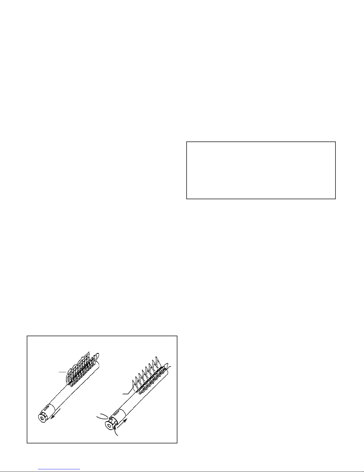
1. The burner air openings (primary air) may need clean
ing. Observe if lint and dust have accumulated.
2. With a small brush, clear away lint and dust which may
have accumulated. Observe if any debris has fallen on
the burner which obstructs the burner ports. See Figure
5 for a view of a comparison of a good flame. If in
doubt, consult a competent serviceman or your local
gas company.
3. Turn thermostat dial up to turn burner “ON”
4. Loosen the air shutter retaining screw.
5. With a screw driver, lightly tap the air shutter and move
it in the more open direction (Figure 5)
6. If yellow flame disappears, tighten the screws, taking
care not to move air shutter again.
7. When flames appear normal (Figure 5) replace burner
access cover.
8. Turn thermostat down to the previous setting.
Tank Clean-Out
A) A clean-out opening is provided for periodic cleaning of
the tank. Gas must be shut off and the heater drained
before opening the clean-out.
B) To clean heater through the clean-out opening, proceed
as follows:
- remove outer door from side of the side of the casing.
- peel back the insulation covering the clean-out flange.
- remove the six (6) hex head screws securing the tank
clean-out plate and remove the plate.
- remove lime, scale or sediment using care not to
damage the glass lining of the tank.
- inspect the clean-out gasket, if it shows sign of wear a
new gasket is required.
- install the clean-out plate. Be sure to draw plate up
tight by tightening screws securely.
- position the insulation, and replace outer door.
NOTE:
In some areas where there is a lot of lime in the
water, the tank should be cleaned more frequently,
otherwise the heater will develop excess scale on the
bottom and cause a banging, rumbling or boiling
noise and will affect the recovery, operation and life of
the heater.
Figure 5
TOO LITTLE AIR.
YELLOW FLAME.
LIKE A CANDLE.
SHARP, CLEARLY DEFINED
INNER CONE, BLUE TIPS
CLOSED
INSUFFICIENT AIR
PRIMARY AIR
OPEN
ADJUST AIR SHUTTER
FOR GOOD FLAME
NOTE:
While moving the air shutter dust particles will be disturbed and drawn into the burner causing a bright, luminous flame. This is temporary and must not be confused
with a yellow tipped, carbonizing flame. Carbonizing
flames are often called “candling” flames because they
look like flames from a burning candle
.
Page 17

Page 16
GENERAL HOUSEKEEPING
As a precaution against fire, and to maintain an adequate flow
of combustion air to the heater:
- Keep the appliance area clear and free from combustible material, gasoline and other flammable
vapours and liquids.
- Keep any ventilation and combustion air openings
unobstructed.
- do not pile cartons, papers or combustible materials on
top or around the heater. Maintain clearances to
combustible construction unobstructed.
TEMPERATURE AND
PRESSURE RELIEF VALVE
The temperature and pressure relief valve (T&P valve) is a
part of the safety equipment on the water heater. In order to
keep the T&P valve functioning properly, operate the valve at
least once a year by lifting the manual lever until water discharges from the overflow pipe.
CAUTION: The water flowing from the valve will be HOT.
Keep hands and feet away from the stream of water.
Take care that discharging water does not damage any
flooring, carpeting or other parts of the building which
may be damaged by water.
See also section on T & P valve in the “installation Section”
WATER TEMPERATURE REGULATION
The thermostat is adjusted to its lowest temperature position
when shipped from the factory. The temperature of the water
can be selected by setting of the temperature dial on the front
of the gas control. The normal setting corresponds to approximately 130
o
F.
GAS CONTROL
The gas control is equipped with an energy cutoff switch,
E.C.O., which functions as a high limit safety switch. When
the water temperature exceeds the fixed cutout temperature,
the switch will cycle open. This will interrupt the pilot valve circuit and stop all gas flow through the control.
Two types of E.C.O. limits are manufactured:
1. Recycling
2. Non recycling.
The recycling E.C.O. switch will open when water temperature
exceeds fixed cutoff temperature. When the temperature in
the tank cools sufficiently (approximately 120
o
F) the switch will
close. This will re-establish the electrical circuit and permit the
pilot to function through E.C.O. If recycling of the E.C.O.
occurs, it indicates that a problem exists in the heater or
installation which must be corrected.
The non-recycling E.C.O. switch will open when water temperature exceeds fixed cutoff temperature. It will not close circuit
again when the water temperature cools. When this contact
opens, it indicates that a problem exists in the heater which
must be corrected before a new control is used in the water
heater. If single cycle energy cutoff switch opens contact, the
control must be replaced.
For gas control replacement, contact your local gas utility, or
a qualified service person. The replacement control must be
an identical model to the control which has been removed.
CAUTION: Label all wires prior to disconnection
when servicing controls. Wiring errors can cause
improper and dangerous operation.
TEMPERATURE
Set temperature as low as possible to provide an adequate
supply of hot water. This will reduce heat loss and extend the
life of the glass lining. Every “notch” on the dial of the gas control corresponds to approximately a 10oincrement in water
temperature.
HIGHER SETTING INCREASES
THE RISK OF SCALD INJURY
In households with children or invalids and elderly, select a
lower temperature setting. To reduce the risk of scalding,
valves for reducing point of use temperature by mixing cold
and hot water are available. Consult a licensed plumber or the
local plumbing authority.
EXPOSURE TO WATER
TAMPERING
Tampering with the thermostat, gas valve, igniter control or
temperature and pressure relief valve is DANGEROUS and
voids all warranties. Only qualified personnel should service
these components.
IMPORTANT
Should the water heater be subjected to flooding,
fire or other unusual condition, turn off gas at the
manual gas shut-off valve and water at the inlet
valve to the heater. Do not put the heater in
operation until a qualified gas technician has
inspected and replaced any part of the gas control
system that has been underwater.
Page 18

Page 17
CATHODIC PROTECTION
Depending on the model, two or three magnesium anodes are
factory installed inside the tank to provide corrosion protection
and to extend tank life. Permanent removal of the anode(s) for
any purpose will void the warranty.
Read the warranty attached to this water heater for a full
explanation of the time period that parts and the heater are
warranted.
It is advisable to inspect the condition of the anode(s) at
certain intervals. A two year period may be a guide to begin
with. The life of the anode depends on many factors and can
differ greatly from one location to another.
To remove and anode, proceed as follows:
1. Turn the gas off at the inlet to the heater.
2. Turn water off at the cold water inlet valve.
3. Open a nearby HOT water tap.
4. Drain approximately two pails full of water from the
heater.
5. Remove the vent pipe and the draft hood. Remove the
hot and cold water connections.
6. Lift up the other casing top and the insulation under it.
7. Lift up the inner flue collector. NOTE: the flue collector
has a lip extending out on the circumference which can
be used for lifting.
8. With a 1-1/6” hex socket wrench, loosen the anode from
the fitting in the tank top.
NOTE: The anodes have been factory installed using a
power tool. It will be necessary for a second person to
restrain the heater. A few sharp blows on the handle of
the socket wrench will loosen the anode adapter.
If an impact wrench (power driven) is available, this is an
easy way to remove an anode.
9. Lift the anode up and inspect. There should be at least
3/8” to 1/2” of anode diameter left. The surface may be
rough, full of pits and crevices, but this is normal.
If there is less than approximately 3/8” diameter left, the
anode needs to be replaced.
10. Apply a good grade of pipe dope to the threads of the
anode adaptor and screw securely into the tank top.
11. Replace the flue collector. Make sure it seals all around
the circumference.
12. Replace the insulation and the casing top.
13. Re-connect hot and cold water lines.
14. Replace the draft hood and the vent pipe. NOTE: If the
vent pipe shows signs of corrosion or damage, replace it
with new material. See section on “Venting”
15. Open the cold water inlet valve and fill the tank.
16. Check for leaks.
17. To relight burners, follow “Lighting Instructions”
DISHWASHING MACHINE REQUIREMENTS
The heater may be operated to supply the 180oF sanitizing
rinse water required by the public health code for dishwashing
machines. In such installations, the heater should be located
as close as possible to the dishwasher. If the distance between
the dishwasher and heater is greater than 5 ft. the pipes
should be insulated and recirculation of the 180
o
F water should
be provided. The circulation flow rate should be enough to
provided 180oF to the dishwasher, however, the rate should be
low to minimize turbulence inside the water heater.
Flow pressures to the dishwasher above 25 or below 15
pounds per square inch will not produce a proper rinse spray.
If flow pressure to the dishwasher is high a pressure reducing
valve should be used in the 180
o
F line to deliver water at 20
pounds per square inch for the rinse cycle. If the flow is too low
a pressure booster should be installed.
MULTIPLE HEATERS IN SINGLE SYSTEM
When two or more water heaters are installed into a single system, the following precautions must be taken to ensure that
each heater is able to deliver it’s full rated capacity of hot water
for maximum system efficiency.
1. Gas supply piping must be large enough (see table 1)
2. The combined flue pipe must be large enough. see
local codes.
3. The water connections must be properly manifolded.
WATER ODOR PROBLEMS
When the area water trace mineral content is high. The odor of
the water may be strong. Replacing the water by draining it
completely and flushing then refilling it may help. Chlorination
and replacement of magnesium anode with aluminum anode
may help if the problem persists.
CAUTION
Hydrogen gas can be produced in a hot water system served by this heater that has not been used
for a long period of time (generally two weeks or
more). Hydrogen gas is extremely flammable. To
reduce the risk of injury under these conditions, it is
recommended that a hot water faucet be opened
for several minutes at the kitchen sink before using
any electrical appliances connected to the hot
water system. If hydrogen is present, there will
probably be an unusual sound such as air escaping
through the pipe as the water begins to flow. There
should be no smoking or open flame near the
faucet at the time it is opened.
Page 19
Page 18
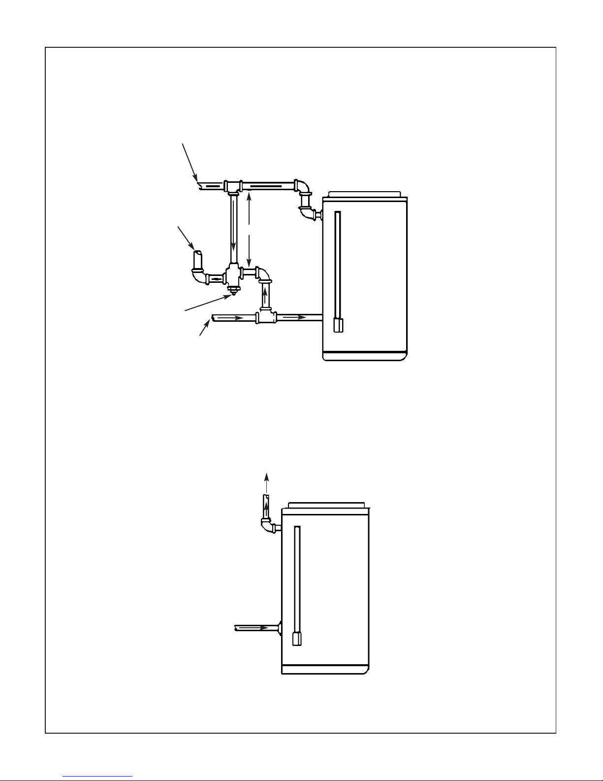
INSTALLATION DIAGRAMS
TWO TEMPERATURE
COLD WATER
INLET
MIXING VALVE
TEMPERED
OUTLET
6” MIN.
SINGLE TEMPERATURE OR BOOSTER
HOT WATER
OUTLET
COLD WATER
INLET OR
TEMPERED
WATER INLET
180
0
TO
DISHWASHER
Page 20
Page 19
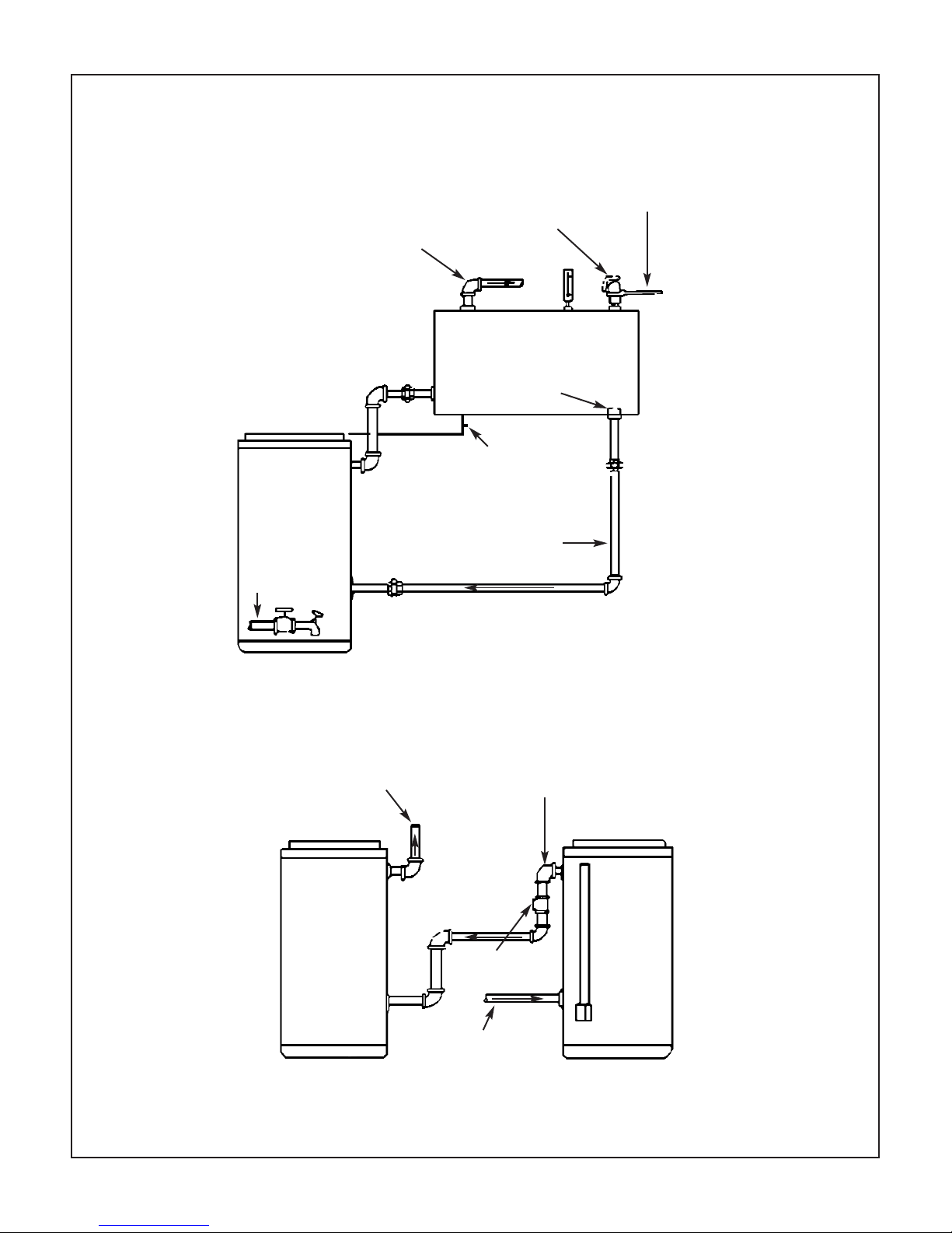
SINGLE TEMPERATURE GRAVITY CIRCULATION
WITH HORIZONTAL STORAGE TANK
STORAGE TANK
(INSULATED)
2” RISER
5” MIN.
1 1/2 MIN.
COLD
WATER
INLET
HOT WATER
OUTLET
T&P RELIEF
VALV E
PIPE TO
OPEN DRAIN
PRE-HEATER
BOOSTER
PRE-HEATER
180
0
TO
DISHWASHER
PRE-HEATER
WATER TO
BOOSTER
HOT WATER
TO FIXTURE
COLD WATER
INLET
Page 21

Page 20
(1) WITH HORIZONTAL STORAGE TANK
STORAGE TANK
(INSULATED)
2” RISER
TEMPERATURE &
PRESSURE RELIEF
VALV E
TANK
TEMPERATURE
CONTROL
PLUG COCK
(1) CHECK
VALV E
(2) COLD
WATER
INLET
3/4” .75
ALL BRONZE
CIRCULATING
PUMP
THERMOMETER
HOT WATER OUTLET
ITEMS 1&2 MUST
BE INSTALLED IN
ORDER SHOWN
(2) WITH VERTICAL STORAGE TANK
T&P
RELIEF
VALV E
PIPE TO
OPEN DRAIN
STORAGE
TANK
(INSULATED)
PLUG COCK
(1) CHECK VALVE
(2) COLD WATER
INLET
3/4” .75
ALL BRONZE
CIRCULATING
PUMP
Page 22
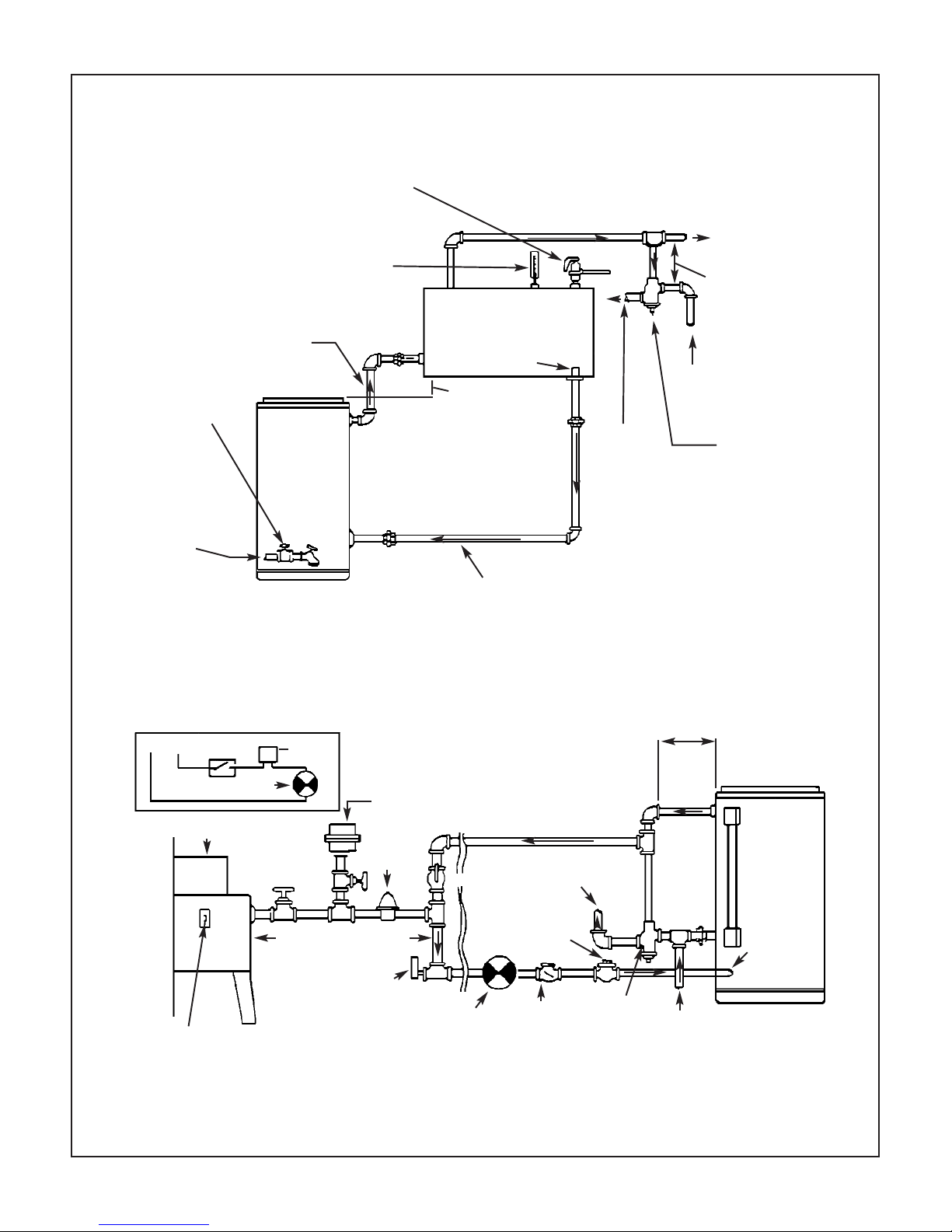
Page 21
TWO TEMPERATURE GRAVITY CIRCULATION
WITH HORIZONTAL STORAGE TANK AND MIXING VALVE
TEMPERATURE &
PRESSURE RELIEF VALVE
THERMOMETER
1-1/2” MIN.
INSULATED
GATE
VALV E
COLD WATER
SUPPLY
1-1/2” MIN.
5” MIN.
TEMPERED
WATER
OUTLET
MIXING VALVE
COLD WATER
SUPPLY
6” MIN.
180
0
TO
DISHWASHER
2” RISER
STORAGE TANK
(INSULATED)
TWO TEMPERATURE FORCED CIRCULATION
WITH 180
O
CIRCULATING LOOP
TOGGLE
SWITCH
+
-
CIRCULATING PUMP
DISHWASHER
WATER HAMMER
ARRESTOR
PRESSURE
REDUCING
VALV E
AS SHORT AS POSSIBLE
WATER TEMPERATURE
CONTROL NOTE 2
3/4 #75
ALL BRONZE
CIRCULATING
PUMP
CHECK VALVE
MIXING
VALV E
COLD
WATER
SUPPLY
DRAIN VALVE
NOTE 4
TEMPERED
WATER OUTLET
PLUG COCK
NOTE 3
AS
SHORT
AS
POSSIBLE
TOGGLE SWITCH NOTE 1
Note 1: Toggle switch controls 180owater circulation.
Install on or close to dishwasher. Close switch when starting
dishwasher. Open switch when dishwasher is not operating.
Note 2: Install water temperature control in an uninsulated
tee in the circulating line ahead of the dishwashing machine
takeoff. Control should be set at 185
0
Note 3: Adjust plug cock so the circulating line flow rates
does not cause unnecessary turbulation in the tank.
Note 4: Return circulating line connection is made through
the water heater drain opening.
WATER
TEMP
CONTROL
Page 23
Page 22
INSTALLATION RECORD
This water heater is protected by a multi-year warranty against
leaks, plus a one year warranty on parts. Record key data here
for future reference and prompt service.
GSW Water Heating Company
599 Hill Street West
Fergus, Ontario, Canada
N1M 2X1
Telephone: (519) 843-1610
Fax: (519) 843-6121
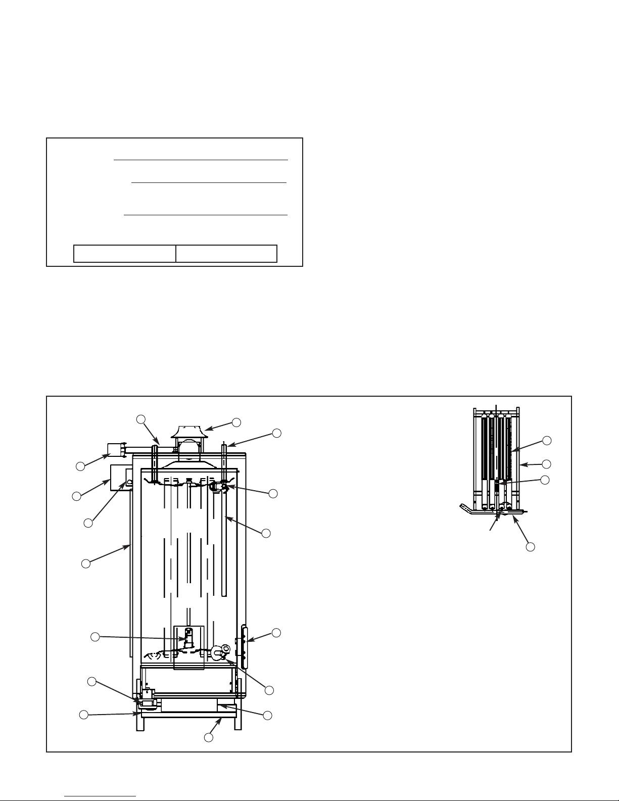
REPAIR PARTS ILLUSTRATION
& SCHEDULE
The following parts may be ordered through your plumber, a
local plumbing supply company, or direct from the factory.
Parts will be shipped at prevailing prices and will be billed
accordingly. Refer to warranty for company address.
WHEN ORDERING REPAIR PARTS, always give the
following information:
(1) Parts description
(2) Model and serial number
(3) Type of gas
(4) Item Number
Please give the complete serial number, consisting of a ten
(10) digit number.
EXAMPLE: Model G10 40 TN Ser. 8901123456
It is imperative that replacement main burner orifices, pilot
burners and thermostats be ordered for the proper gas type.
Natural gas thermostats will be marked with a 3.5 pressure
setting. Propane gas thermostats will be marked with a 10.0
pressure rating.
Installed by
Installation date
Location of Gas
Shut-off Valve
Model Number Serial Number
6
28
18
19
21
22
1
3
11
16
9
12
5
8
4
7
13
16
14
15
ORIFICE AND AIR
SHUTTER DETAIL
PARTS IDENTIFICATION
1. Gas Control
2. Gas Supply tube
3. Burner Tray and manifold ( for details see
items 13 to 16)
4. Cold water supply nipple
5. Dip tube
6. Hot outlet nipple
7. Draft hood
8. T&P valve
9. Drain valve
10. Burner access cover
11. Drip tray
12. Cleanout cover
13. Gas manifold
14. Burner tray
15. Gas burner
16. Pilot & thermocouple assembly (E.I. ModelHot Surface Pilot)
17. Burner orifice
18. Junction box cover
19. Junction box assembly
20. Vent damper
21. Plastic channel
22. Thermostat
23. Wire harness (not shown)
24. Transformer (not shown)
E.I. MODEL
Page 24
Page 23
*THREE YEAR WARRANTY
IMPORTANT: Fill out this Warranty and keep for future reference.
MODEL NO. SERIAL NO. DATE INSTALLED
Owner:
INSTALLATION ADDRESS:
GSW WATER PRODUCTS COMPANY warrants that:
If within one year after original installation of a GSW water heater, any part or portion becomes defective in material or workmanship, GSW at its option, will repair
or replace such part.
If the glass lined steel tank in the heater leaks due to rust or corrosion within the first *three years after the original installation, GSW will supply a complete new
water heater of equivalent size and rating, and the then current model.
The replacement heater will carry a warranty equal to the unexpired portion of the original heater warranty.
A water heater should not be installed in a location where water damage can result if the water heater develops a leak. This is particularly important if the water heater
is installed in a multi-story building.
In such cases, provision should be made in the installation for a means of directing to a drain pipe, any water escaping from the water heater.
The Company accepts no responsibility for damage caused by a leaking water heater.
This warranty shall only be effective while the heater remains installed in its original location in accordance with applicable plumbing and building codes, ordinances
and regulations, and company instructions, and if and when:
(a) written notice is given to the Company promptly following discovery of any defect in the heater.
(b) all information which may be reasonably requested by the Company relating to the purchase, transportation, operation and installation of the heater is supplied
when so requested.
(c) the defective part or heater is returned, when so requested by the Company, transportation prepaid to an address designated by the Company complete
with all components properly and securely packed and if inspection by the Company proves the part or heater to be defective in workmanship or material.
(d) the heater has been subjected only to normal hot water supply conditions, that is at temperatures not exceeding the maximum setting of the thermostat
and/or automatic gas shut-off control; at water pressures not exceeding the pressure rating shown on the heater, in non-corrosive atmospheres with fresh
water or non-corrosive chemicals, circulating through, or stored in , the heater, when completely full of liquid and with tank free of excessive scale or lime
deposits.
(e) the heater has been used only with a properly operating temperature and pressure relief valve as supplied with the heater or installed in conformity with
Company instructions applicable to the specific heater model.
All repairs and replacements of parts or heaters shall be f.o.b. point of distribution and the Company shall not be liable for shipping, labour, or installation costs.
Any accident to the water heater, misuse, abuse (including freezing), alteration, modified operation or faulty repair will void this warranty.
NO OTHER WARRANTY, EXPRESSED OR IMPLIED, HAS BEEN OR WILL BE MADE ON BEHALF OF THE COMPANY WITH RESPECT TO THE HEATER
OR THE INSTALLATION, OPERATION, REPAIR OR REPLACEMENT OF THE HEATER. THE COMPANY SHALL NOT BE LIABLE BY VIRTUE OF THIS
WARRANTY OR OTHERWISE FOR ANY CONTINGENT DAMAGES OR OTHER CHARGES ALLEGED TO HAVE ARISEN IN CONNECTION WITH HEATERS
OR PARTS CLAIMED TO BE DEFECTIVE. THE COMPANY’S WARRANTY IS A LIABILITY ONLY OF THE COMPANY AND SHALL NOT BE CONSTRUED
A LIABILITY OF ANY PERSON DEALING WITH THE HEATER. SPECIFICALLY IT SHALL NOT BE CONSTRUED AS AN IMPLIED TERM OF ANY CONTRACT
OF PURCHASE AND SALE OF THE HEATER.
*TWO YEARS FOR INSTALLATION IN THE PROVINCE OF SASKATCHEWAN.
Any notice or other communication to the Company, under the terms hereof, shall be in writing and delivered personally or mailed to the Company at the following
address:
COMMERCIAL
WATER HEATER WARRANTY
599 Hill Street West
WARRANTY
GLASS-LINED
GAS FIRED
COMMERCIAL
WATER HEATER
 Loading...