

GSW WATER HEATING
599 Hill Street West
Fergus, ON, Canada N1M 2X1
To obtain technical, warranty or service assistance during
or after the installation of this water heater, call toll free:
1-888-479-8324
When calling for assistance, please have the following
information ready:
1. Model number
2. 5 digit product number
3. Serial number
4. Date of installation
5. Place of purchase
Table of Contents . . . . . . . . . . . . . . . . . . . . . . . . . . . . 2
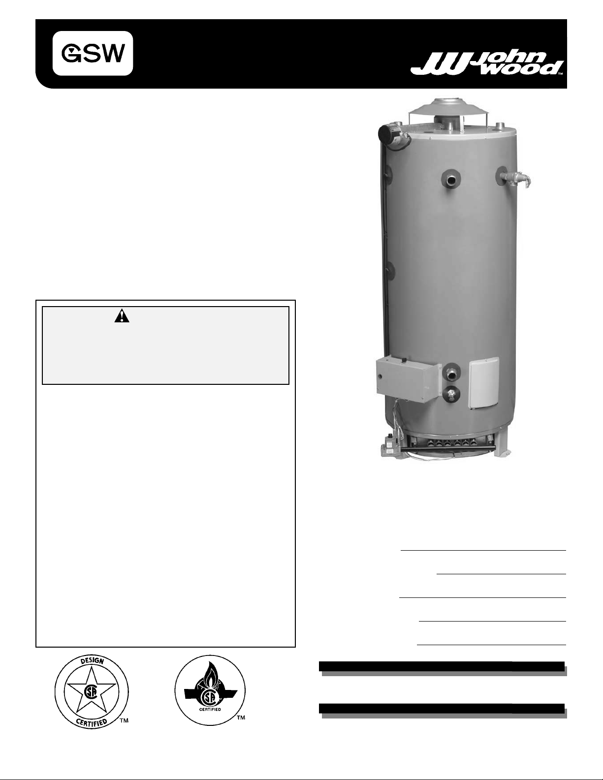
Commercial Gas
Water Heater
Installation
Instructions and
Use & Care Guide
for Signature Series models with prefix JWS and AJWS
70305 REV.C (06-01)
WARNING:
If the information in these instructions is
not followed exactly, a fire or explosion
may result causing property damage, personal injury or death.
Do not store or use gasoline or other flammable vapours and liquids in the vicinity of
this or any other appliance.
WHAT TO DO IF YOU SMELL GAS
• Do not try to light any appliance.
• Do not touch any electrical switch; do
not use any phone in your building.
• Immediately call your gas supplier from
a neighbor’s phone. Follow the gas supplier’s instructions.
• If you cannot reach your gas supplier,
call the fire department.
Installation and service must be performed
by a qualified installer, service agency or
the gas supplier.
GSW Water Heating is a division of GSW Water Products Inc.
2
Your safety and the safety of others is very important.
We have provided many important safety messages in this manual and on your appliance.
Always read and obey all safety messages.
All safety messages will tell you what the potential hazard is, tell you how to reduce the
chance of injury, and tell you what can happen if the instructions are not followed.
This is the safety alert symbol.
This symbol alerts you to potential hazards that can kill or hurt you and others.
All safety messages will follow the safety alert symbol and either the word
“DANGER” or “WARNING”.
DANGER
WARNING
You can be killed or seriously injured if you don’t immediately follow
instructions.
You can be killed or seriously injured if you don’t follow instructions.
Important Instructions
• Do not use this appliance if any part has been under water. Immediately call a qualified service technician. Water
heaters subjected to flood conditions or anytime the gas controls, main burner or electrical components have been
submerged in water require replacement of the entire water heater.
• Hydrogen gas can be produced in a hot water system served by this heater that has not been used for a long period of time (generally two (2) weeks or more). Hydrogen gas is extremely flammable
and can ignite when
exposed to a spark or flame. To reduce the risk of injury under these conditions, it is recommended that the hot
water faucet be opened for several minutes at the kitchen sink before using any electrical appliance connected to
the hot water system. Use caution in opening faucets. When hydrogen is present, there will probably be an unusual
sound such as air escaping through the pipe as the water begins to flow. There should be no smoking or open
flame near the faucet at the time it is open.
The California Safe Drinking Water and Toxic Enforcement Act requires the Governor of California to publish a list of substances known to the State of California to cause Cancer, birth defects, or other reproductive harm, and requires businesses to warn of potential exposure to such substances.
WARNING: This product contains a chemical known to the State of California to cause cancer, birth defects, or other
reproductive harm.
This appliance can cause low-level exposure to some of the substances listed, including formaldehyde, carbon monoxide, and soot.
Table of Contents
Water Heater Safety . . . . . . . . . . . . . . . . . . . . . . . . . . . . . . . . . . . . . 1-2
Installation Instructions . . . . . . . . . . . . . . . . . . . . . . . . . . . . . . . . . . . 3-5
Combustion Air Supply and Ventilation . . . . . . . . . . . . . . . . . . . . . . 5-8
Water System Piping . . . . . . . . . . . . . . . . . . . . . . . . . . . . . . . . . . . 8-12
Gas Supply and Piping . . . . . . . . . . . . . . . . . . . . . . . . . . . . . . . . . 12-14
Electrical Connections . . . . . . . . . . . . . . . . . . . . . . . . . . . . . . . . . . . . 15
Wiring Diagram . . . . . . . . . . . . . . . . . . . . . . . . . . . . . . . . . . . . . . . . . 16
Installation Checklist . . . . . . . . . . . . . . . . . . . . . . . . . . . . . . . . . . . . . 17
Operating Your Water Heater . . . . . . . . . . . . . . . . . . . . . . . . . . . . 17-19
Maintenance of Your Water Heater . . . . . . . . . . . . . . . . . . . . . . . 20-21
Trouble Shooting Chart . . . . . . . . . . . . . . . . . . . . . . . . . . . . . . . . 22-23
Repair Parts Illustration . . . . . . . . . . . . . . . . . . . . . . . . . . . . . . . . . . . 24
Warranty . . . . . . . . . . . . . . . . . . . . . . . . . . . . . . . . . . . . . . . . . . . . . . 25
INSTALLATION INSTRUCTIONS
Consumer Information
This water heater is design-certified by CSAInternational as
a Category I, non-direct vented water heater which takes its
combustion air either from the installation area or from air
ducted to the unit from the outside.
This water heater must be installed according to all local
and state codes, or in the absence of local and state codes,
with the “National Fuel Gas Code”, ANSI Z223.1(NFPA 54)latest edition. Canadian installations must be performed in
accordance with CAN/CSA-B149.1. This is available from
the following:
American Gas Association
1515 Wilson Boulevard
Arlington, VA 22209
National Fire Protection Agency
1 Batterymarch Park
Quincy, MA 02269
Canadian Standards Association
5060 Spectrum Way
Mississauga, ON
L4W 5N6
Check the phone listings for the local authorities having
jurisdiction over this installation.
Installer and Owner Responsibilities
This manual has been prepared to acquaint you with the
installation, operation and maintenance of this gas water
heater and provide important safety information in these
areas.
Read all of the instructions thoroughly before attempting the
installation or operation of this water heater . Keep this manual for future reference.
Do not discard this manual. You or future users of this water
heater will need it for future reference.
The manufacturer and seller of this water heater will not be
liable for any damages, injuries or deaths caused by failure
to comply with the inst
allation and operating instructions
outlined in this manual.
The manufacturer of this water heater recommends that
it be professionally installed by qualified service technicians. Examples of qualified service technicians
include: those trained in the plumbing and heating
industry, local gas utility personnel or an authorized
service person.
Massachusetts code requires this water heater to be
installed in accordance with Massachusetts Plumbing and
Fuel Gas Code 248 CMR Sections 2.00 and 5.00.
A data plate identifying this water heater can be found on
the front of the water heater. When referring to this water
heater always have the information listed on the data plate
readily available.
Retain your original receipt as proof of purchase.
Unpacking the Water Heater
Removing Packaging Materials
Important: Do not remove any permanent instructions,
labels, or the data label from outside of the water heater or
on the inside of panels.
• Remove exterior packaging and place installation components aside.
• Inspect all parts for damage prior to installation and startup.
• Completely read all instructions before attempting to
assemble and install this product.
• After installation, dispose of packaging material in the
proper manner.
Installation Requirements
The water heater must be installed according to all local and
state codes, or in the absence of local and state codes, the
"National Fuel Gas Code”, ANSI Z223.1 (NFPA 54)-latest
edition. Canadian installations must be performed in accordance with CAN/CSA-B149.1.
Note: In the State of California, the water heater must be
braced, anchored, or strapped to avoid moving during an
earthquake. Contact local utilities for code requirements in
your area or call 1-888-479-8324 and request instructions.
Site Location
• Select a location near the center of the water piping system. The water heater must be installed indoors and in a
vertical position on a level surface. DO NOT install in
bathrooms, bedrooms, or any occupied room normally
kept closed.
• Locate the water heater as close to the gas vent as practical. Consider the vent system piping and combustion air
supply requirements when selecting the water heater
location. The venting system must be able to run from the
water heater to termination with minimal length and
elbows.
• Locate the water heater near the existing gas piping. If
installing a new gas line, locate the water heater to minimize the pipe length and elbows.
• The water heater should be located in an area not subject
to freezing temperatures. Water heaters located in
unconditioned spaces (i.e. attics, basements, etc.) may
3
Excessive Weight Hazard
Use two or more people to move and install
water heater. Failure to do so can result in
back or other injury.
WARNING
require insulation of the water piping and drain piping to
protect against freezing. The drain and controls must be
easily accessible for operation and service. Maintain
proper clearances as specified on the data plate.
• The operation of air-moving devices such as exhaust
fans, ventilation systems, clothes-dryers, fire-places, etc.,
can affect the proper operation of the water heater. Note:
Special attention must be given to the location of these
devices and the conditions they may create. Flow reversal of flue gases may cause an increase of carbon
monoxide inside of the dwelling.
Important: Air for combustion and ventilation must not
come from a corrosive atmosphere. Any failure due to corrosive elements in the atmosphere is excluded from warranty coverage.
The following types of installation (but not limited to the following) will require outdoor air for combustion due to chemical exposure, and may reduce but not eliminate the presence of corrosive chemicals in the air:
• Beauty shops
• Photo processing labs
• Buildings with indoor pools
• Water heaters installed in laundry, hobby or craft rooms
• Water heaters installed near chemical storage areas
Clearances and Accessibility
Notice: Minimum clearances from combustible materials
are stated on the data plate located on the front of the water
heater.
• If the water heater is installed in a restaurant or food service location where the floor is cleaned frequently, NSF
International requires the water heater to maintain
152mm (6 in) of clearance above the floor. To comply with
the NSF International requirement, install leg extension
kit. For availability contact 1-888-479-8324
• The water heater is certified for installation on a combustible floor.
4
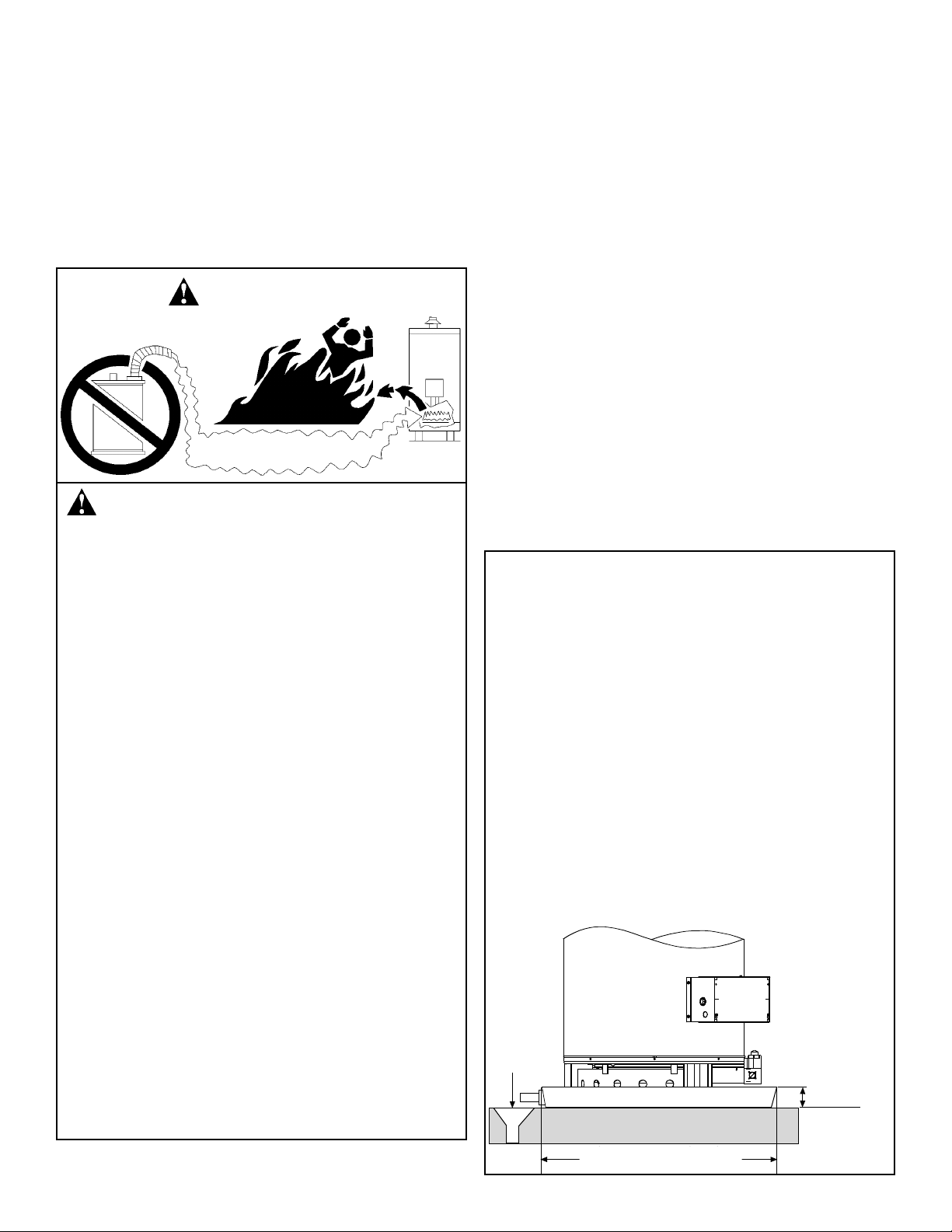
Vapours from flammable liquids will
explode and catch fire causing death or
severe burns.
Do not use or store flammable products
such as gasoline, solvents or adhesives in
the same room or area near the water heater.
Keep flammable products:
1. far away from heater;
2. in approved containers;
3. tightly closed; and
4. out of children’s reach.
This water heater has a main burner and an
automatic ignition system. The ignition system:
1. can come on at any time; and
2. will ignite flammable vapours.
Vapours:
1. cannot be seen;
2. are heavier than air;
3. go a long way on the floor; and
4. can be carried from other rooms to the
water heater by air currents.
Do not install this water heater where flammable products will be stored.
WARNING
FLAMMABLE VAPOURS
Important:
The water heater should be located in an area where leakage of the tank or connections will not result in damage to
the area adjacent to the water heater or to lower floors of
the structure. Due to the normal corrosive action of the
water, the tank will eventually leak after an extended
period of time. A suitable metal drain pan should be
installed under the water heater as shown below, to help
protect the property from damage which may occur from
leaks in the piping connections or tank. The pan must limit
the water level to a maximum depth of 45mm (1 3/4 in) and
be 50mm (2 in) wider than the water heater and piped to an
adequate drain. The pan must not restrict combustion
airflow. Locate the water heater near a suitable indoor
drain. Outside drains are subject to freezing temperatures
which can obstruct the drain line. The piping should be at
least 19mm (3/4 in) ID and pitched for proper drainage.
Under no circumstances will the manufacturer or seller of
this water heater be held liable for any water damage which
is caused by your failure to follow these instructions.
FLAMMABLES
1 3/4” Max
Pipe to
adequate
drain
At least 2” greater than the
diameter of the w ater heater
Pipe to
adequate
drain
45mm max.
(1¾ in)
At least 50mm (2 in) greater than
the diameter of the water heater.
Important: If installing over carpeting, the carpeting must
be protected by a metal or wood panel beneath the water
heater. The protective panel must extend beyond the full
width and depth of the water heater by at least 76mm (3 in)
in any direction, or if in an alcove the entire floor must be
covered by the panel. The panel must be strong enough to
carry the weight of the water heater when full of water.
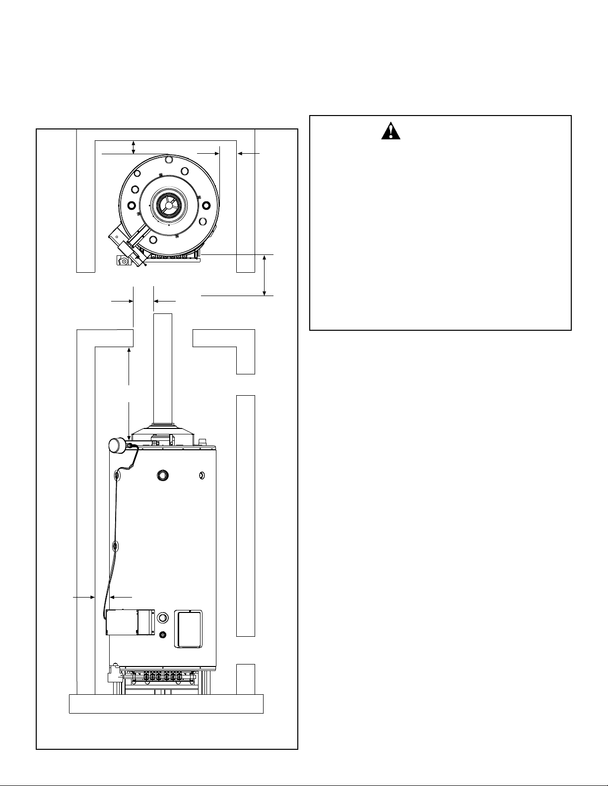
Figure 1 may be used as a reference guide to locate the
specific clearance locations. Aminimum of 610mm (24 in) of
front clearance and 102mm (4 in) on each side should be
provided for inspection and service.
COMBUSTION/VENT PIPE SYSTEM
Combustion
Combustion air must be free of acid-forming chemicals.
These chemicals are found in aerosol sprays, detergents,
bleaches, cleaning solvents, air freshener , paint and varnish
removers, refrigerant, and many other commercial products. When burned, vapours from these products form highly corrosive acid compounds. These products should not be
stored or used near the water heater or air inlet.
Venting
Vent pipe inst allation must be installed according to all state
and local codes, or in the absence of local and state codes,
the National Fuel Gas Code, NFPA 54, ANSI Z223.1-latest
edition. Canadian installations must be performed in accordance with CAN/CSA-B149.1.
It is the responsibility of the installing contractor to provide a
vent adequate in capacity and in good usable condition.
Btu/hr capacity limitations are governed by the style and
height of the vent/chimney. For installations in the United
States, capacity tables are available in the National Fuel
Gas Code (ANSI Z223.1- latest edition). Canadian installation information can be found in CAN/CSA-B149.1
U.L. recognized fuel gas and carbon monoxide (CO) detectors are recommended in all applications and should be
installed using the manufacturer’s instructions and local
codes, rules, or regulations.
Important: Check to make sure the vent pipe is not blocked
in any way.
• Venting should be as direct as possible with a minimum
number of pipe fittings.
5
Vent
Top to
ceiling
Sides
Front 24” min.
for service
Sides
Back
Top View
Front View
Figure 1: Minimum Clearance Locations
Carbon Monoxide Hazard
Follow all instructions to locate and install
the vent pipe system.
Instructions can be found in this manual, in
state or local codes (or authority having
jurisdiction), or in the absence of such, the
National Fuel Gas Code, ANSI Z223.1, NFPA
54, latest edition. Canadian installations
must be performed in accordance with
CAN/CSA-B149.1
Failure to properly locate and install the vent
pipe system can result in death, explosion,
or carbon monoxide poisoning.
WARNING
Front 610mm (24 in)
min. for service
• Exhaust gas vents must be installed with U.L.listed type
B vent pipe according to the vent manufacturer’s instructions and the terms of its listing.
• Single wall vent connectors must have 152mm (6 in) of
clearance from unprotected combustible surfaces.
• If sidewall venting is necessary, a power vent kit is
required. For availability contact 1-888-479-8324.
• Vents that run through unconditioned spaces where
below freezing temperatures are expected should be
properly insulated to prevent freezing.
• Existing vent systems must be inspected for obstructions,
corrosion and proper installation.
• Vents must be connected to the water heater’s drafthood
by a certified vent connector or by directly originating at
the drafthood opening.
• Some models are shipped with a vent reducer. The vent
reducer can be installed directly to the drafthood if the
existing vent system is adequately sized to support the
exhaust gases.
• Vertical gas vents must terminate with a listed cap or
other roof assembly and be installed according to their
manufacturer’s instructions.
• Horizontal vent connections must have an upward slope
of at least 21mm per metre (1/4 in per foot).
• Gas vents must be supported to prevent damage, joint
separation, and maintain clearances to combustible
materials.
• Vent connection joints should be fastened by sheet metal
screws or by other approved methods.
• Vent and vent connectors should have adequate support
to keep weight off the drafthood.
All pipe, fittings, and procedures must conform to American
National Standard Institute and American Society for Testing
and Materials (ANSI/ASTM) standards in the United States.
Important: If you lack the necessary skills required to properly install this venting system, you should not proceed, but
get help from a qualified service technician.
Air Requirements
General
Where an exhaust fan or any other air consuming appliance
(Eg. Clothes dryer, furnace, etc.) is installed in the same
space as the water heater, sufficient air openings must be
available to provide fresh air when all appliances are oper-
ating simultaneously.
The area in which the heater is located is classified as either
“an unconfined space” or “a confined space”.
An unconfined sp
ace is defined as a sp ace having a volume
not less than 50 cubic feet per 1000 BTU/hour (4.8 cubic
meters per kilowatt) of combined input rating of all appliances using the space. Adjacent open rooms may be included as part of the unconfined space. There shall be no
closeable doors between these rooms. An example of
this is an open basement.
A confined sp
ace is one smaller than described above. Air
shall be supplied through permanent openings as described
in Figure 2. At no time shall an air opening have a dimen-
sion of less than 76mm (3 in) and at no time shall any top
opening be lower than the top of the water heater.
For buildings that are not well sealed (do not have tight fitting doors and windows) natural air infiltration may provide
sufficient air required for combustion and ventilation. For
buildings using tight construction (newer and renovated
structures), the air supply shall be introduced from the outdoors, regardless of whether the space is confined or
unconfined.
Combustion Air “Supply” Ducts
Air supply ducts shall be of galvanized steel or equivalent
corrosion resistant material. A single air duct may not be
substituted when required for upper and lower air openings.
Horizontal upper combustion air ducts shall not slope
downward toward the air inlet.
Louvers and Grills
Openings for air supply ducts must provide free unobstructed air movement. Louver and grill openings must be sized
to ensure that the FREE OPEN AREAis never less than the
area of the air duct.
LOCATION:
The location for top and bottom openings are as follows;
For U.S. installations: The top opening shall commence
within 305mm (12 in) of the top of space and the bottom
opening shall commence within 305mm (12 in) of the bottom of the enclosure.
For Canadian installations: The top opening shall be
located as close to the ceiling as practical but never lower
than the relief opening of the lowest draft control device.
The bottom opening shall be located neither more than
457mm (18 in), nor less than 152mm (6 in), above floor
level.
6
An adequate air supply shall be provided for
combustion and ventilation of this water
heater.
An insufficient supply can result in poor
combustion and possible sooting of the
burner, combustion chamber, or flue passageway. This may present a potential fire
hazard or create a serious health hazard by
producing carbon monoxide.
WARNING
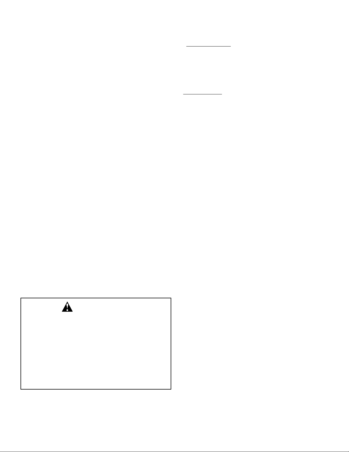
Air Opening Requirements
(a) EQUIPMENT LOCATED IN CONFINED SPACES; ALL AIR FROM
INSIDE THE BUILDING.
Two permanent openings (top and bottom) shall be provided connecting
the confined space (e.g., closet/small room) with the unconfined space.
Each opening shall have a free area of one square inch per 1,000
BTU/hour (22 cm²/kW) input of all appliances in the confined space, but not
less than 100 square inches (645 cm²).
(b) BASEMENT INST ALLATION, EQUIPMENT LOCATED IN CONFINED
SPACES; ALL AIR FROM OUTDOORS.
Outside air inlets shall be a minimum of 305mm (12 in) above the grade
(snow) line. When supplying air directly from the outdoors:
For American installations: Two openings (top and bottom) shall be provided with each opening having a minimum free area of one square inch
per 4,000 BTU/hour input (5.5 cm²/kW) of total input rating of all appliances
in the confined space.
For Canadian installations: Canadian codes specify single air supply
source. Canadian customers and authorities having jurisdiction may use
the sizing listed in Table 1. When using a single air supply, the duct shall
terminate within 305mm (12 in) above and within 610mm (24 in) horizontally from the burner level of the appliance having the largest input.
(c) EQUIPMENT LOCATED IN CONFINED SPACES; ALL AIR FROM
OUTDOORS.
For American installations: When supplying air directly from the out-
doors using horizontal ducting, each opening shall have a free minimum
area of one square inch per 2,000 BTU/hour (11 cm²/kW) of total input rating of all appliances in the confined space.
For Canadian installations: Refer to Table 1 of part (b).
(d) EQUIPMENT LOCATED IN CONFINED SPACES; ALL AIR FROM
OUTDOORS THROUGH VENTILATED ATTIC.
For American installations: When supplying air directly through vertical
ducting, each opening shall have a free minimum area of one square inch
per 4,000 BTU/hour (5.5 cm²/kW) of total input rating of all appliances in
the confined space.
7
Combustion
Air Duct
Permanent
Ventilation
Air
12” Grade
12”
Outdoor
Air Ducts
Venting
Combustion
Inlet
Air Ducts
Outlet Air
(a)
(b)
(d)
(c)
Figure 2: Equipment Location and
Combustion/Ventilation Air
Requirements
*U.S. installations require a dual duct system.
A
1
B
2
BTU/h (kW) mm2 (in2) mm (in) mm (in)
75,000 (23) 7,000 (11) 100 (4) 125 (5)
100,000 (30) 9,000 (14) 100 (4) 125 (5)
125,000 (37) 12,000 (18) 125 (5) 150 (6)
150,000 (45) 14,000 (22) 125 (5) 150 (6)
175,000 (53) 16,000 (25) 150 (6) 175 (7)
200,000 (60) 19,000 (29) 150 (6) 175 (7)
225,000 (68) 21,000 (32) 150 (6) 175 (7)
250,000 (75) 23,000 (36) 175 (7) 200 (8)
275,000 (83) 26,000 (40) 175 (7) 200 (8)
300,000 (90) 28,000 (43) 175 (7) 200 (8)
325,000 (98) 30,000 (47) 200 (8) 225 (9)
350,000 (105) 32,000 (50) 200 (8) 225 (9)
375,000 (113) 35,000 (54) 200 (8) 225 (9)
400,000 (120) 37,000 (58) 225 (9) 250 (10)
Combined input of
all appliances in
conf ined space
Required free
area of duct
Acceptable equivalent
duct diameter
Table 1
Notes:
1. Maximum length of ducts in column Ais 6.1 equivalent metres (20 ft).
2. Maximum length of ducts in column B is 15.2 equivalent metres (50 ft).
305mm
(12 in)
305mm
(12 in)
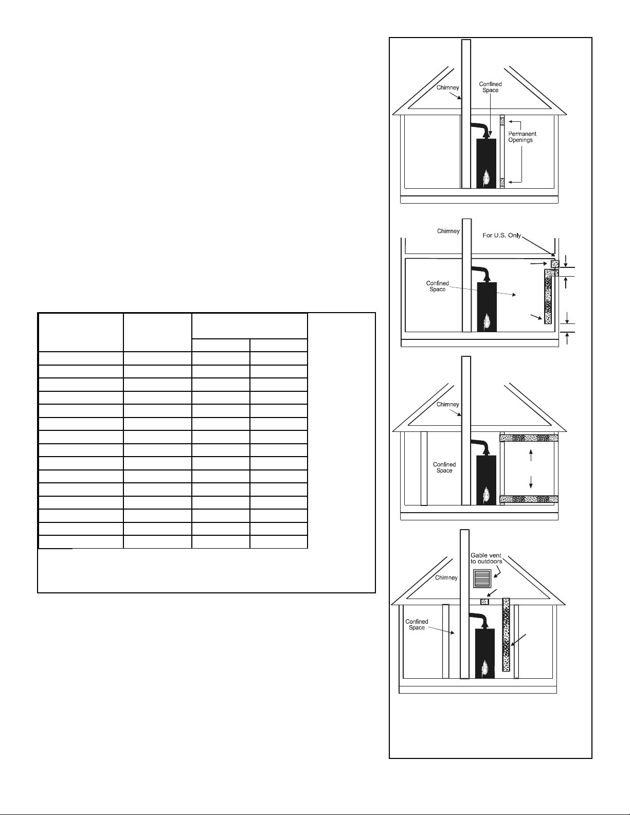
Drafthood/Damper Installation
Install the supplied drafthood and damper on the flue outlet
collar. Use only the supplied drafthood and damper, DO
NOT use any substitute or alter the components in any way.
Place the damper on the water heater (see figure 3A). Align
the four pilot holes on top of the water heater with the 4 corresponding holes on the damper bracket and secure with
the supplied screws. Next, align the drafthood legs with the
4 corresponding pilot holes on top of the water heater and
attach securely with the supplied screws. Locate the wiring
from the ECO, and attach it to the wiring harness on the
damper (see Figure 3A). Once damper is installed, ensure
that the damper position indicator is visible (See figure 3A).
Flue Outlet Reducer
Some units are shipped with a flue outlet reducer (See
Figure 3B). Use only the flue outlet reducer supplied with
this unit. The flue outlet reducer should be connected to the
top of the flue damper and sealed by high temperature silicon. The vent pipe must be installed according to all local
and state codes or, in the absence of local and state codes,
the “National Fuel Gas Code”, ANSI Z223.1(NFPA54)-latest
edition. Canadian installations must be performed in accordance with CAN/CSA-B149.1.
WATER SYSTEM PIPING
Piping Installation
Piping, fittings, and valves should be installed according to
the installation drawing (Figure 4). If the indoor installation
area is subject to freezing temperatures, the water piping
must be protected by insulation. Water supply pressure
should not exceed 80% of the working pressure of the water
heater. The working pressure is stated on the water heater’s
data plate. If this occurs, a pressure reducing valve with a
bypass should be installed in the cold water inlet line to the
entire system. This should be placed on the supply to the
entire structure in order to maintain equal hot and cold water
pressures.
Note: Water supplied to the unit that exceeds 12 grains
(205 mg/l) total hardness may reduce the life and performance of the water heater. Depending on the degree of hardness, it is recommended that either a water pre-treatment
system or a water softener be installed and properly maintained.
Important: Heat cannot be applied to the water fittings on
the water heater as they may contain nonmetallic parts. If
solder connections are used, solder the pipe to the adapter
before attaching the adapter to the hot and cold water fittings.
1. The water heater may have three water piping connection points. The top and front are 1 - 1/2” NPT and the
connections on the back of some heaters are 2” NPT.
When using front or back connections a combination
nipple inlet tube is required (top entry uses a dip tube).
Any one of the options listed in Table 5 may be used.
For availability contact 1-888-479-8324.
8
Do not operate heater with damper in closed
position, it must be in the open position during water heater operation. Do not negate
the action of any existing safety or operational controls.
WARNING
Bracket screws
Draft hood screws
Draft hood
Damper motor
Damper wiring harness
ECO wiring harness
Damper in OPEN position
Damper wiring harness
Damper motor
Damper position indicator
Figure 3A: Flue Damper Assembly
Damper in OPEN position
Damper wiring harness
Damper motor
Flue outlet reducer
High
temperature
silicon sealant
Figure 3B: Flue Outlet Reducer

Note: Inlet and outlet piping connections cannot be mixed.
For example, a top inlet connection must use a top outlet
connection.
2. The installation of unions in both the hot and cold water
supply lines is recommended for ease of removing the
water heater for service or replacement.
3. Since most commercial installations utilize higher temperatures, the use of a tempering valve is strongly
recommended in all domestic hot water lines (i.e.
public restroom sinks, etc).
4. If installing the water heater in a closed water system,
install an expansion tank in the cold water line as specified under “Closed System/Thermal Expansion” (Page
12).
5. Install a shut-off valve in the cold water inlet line. It
should be located close to the water heater and be easily accessible. Know the location of this valve and how
to shut off the water to the heater.
6. The water heater is shipped with a factory-installed
Temperature and Pressure Relief Valve. Install a discharge line in the opening in the T & P valve (see
instructions on Page 13).
7. After piping has been properly connected to the water
heater, remove the aerator at the nearest hot water
faucet. Open the hot water faucet and allow the tank to
completely fill with water. To purge the lines of any
excess air, keep the hot water faucet open for 3 minutes
after a constant flow of water is obtained. Close the
faucet and check all connections for leaks.
Space Heating
If this unit is to be used to supply both space heating and
domestic potable (drinking) water then the following instructions must be followed:
1. All piping and components used must be suitable for
use with domestic (potable) drinking water.
2. Do not use piping or components that have been connected to a nonpotable system or treated with chromates or other toxic chemicals. Do not add any chemicals to the water heater piping.
3. If system requires temperatures in excess of 49°C
(120°F) install a tempering valve, per the manufacturers
instructions, in the domestic (potable) hot water line to
limit the risk of scalding (See Figure 5).
4. Be sure to follow the manual(s) shipped with the heating system. Also follow any state or local codes.
Tempering Valve Installation
A Tempering Valve should be installed per the manufacturer’s instructions in the hot water line. See Figure 5 for sample tempering valve installation.
Please note the following:
DO NOT install this water heater with iron piping. The system should be installed only with piping that is suitable for
potable (drinkable) water such as copper, CPVC, or polybutylene.DO NOT use PVC water piping.
DO NOT use any pumps, valves, or fittings that are not
compatible with potable water.
DO NOT use valves that may cause excessive restriction to
water flow. Use full flow ball or gate valves only.
DO NOT use 50/50 tin-lead solder (or any lead based solder) in potable water lines. Use 95/5 tin-antimony or other
equivalent material.
DO NOT tamper with the gas valve/thermostat, igniter, or
temperature and pressure relief valve. Tampering voids all
warranties. Only qualified service technicians should service these components.
DO NOT use with piping that has been treated with chromates, boiler seal, or other chemicals.
DO NOT add any chemicals to the system piping which will
contaminate the potable water supply.
9
Follow the tempe r in g
valve manufacturer’s
instructions.
Cold
Water
Inlet
Hot
Water
Outlet
Tempered water
to fixtures
Tempering valve
(Set to 120°F)
Figure 5: Tempering Valve
Water Heater
Model B ase #
Dip Tube
Inlet Tube
(Optional F ront )
Inlet Tube
(Optional Bac k )
75-125 60238 60239 60239
80-199 60053 60057 60057
80-250 60053 60057 60057
100-199 71325 75085 75086
100-270 71325 75085 60023
75-300 60053 60057 60057
75-360 N/A 60194 60195
75-399 N/A 60194 60195
75-300NO
x N/A 60194 60195
75-350NO
x N/A 60194 60195
Table 5: Dip Tube Useage
Hot Water
Outlet
Unions
Cold Water
Inlet Valve
Discharge line
6” max. above
drain
Cold Water
Supply to Fixtures
In a closed system use a
Thermal Expa nsion Tank
Temperature and
Pressure Relief Valve
Drain line
3/4” ID min.
Drain
Metal drain
pan 1 3/4”
depth max.
Pressure Reducing
Valve with Bypass
Main Water
Supply
Figure 4: Water Piping Installation
Massachusetts:
Install a vacuum relief
in cold water line per
section 19MGL 142
Drain line
19mm (3/4 in)
ID min.
Discharge line
152mm (6 in)
max. above
drain
Metal drain
pan 45mm
(1-3/4 in.)
depth max.

10
Thermometer
Temperature and
Pressure Relief Valve
Hot Water
to Fixtures
Temperature and
Pressure Relief Valve
Typical
Booster
Heater
Pre-Heater
Pre-Heated
Water to
the Booster
Outlet
Boosted
Temperature
1 1/2” Cold
water supply
Thermal
Expansion
Tank
Pressure
Reducing
Valve
Thermometer
Shut-off valve
Shut-off valve
Check Valve
Shut-off valve
Shut-off valve
Figure 6: Commercial Unit with Auxiliary Booster Heater - Two Temperature (With or Without Building Recirculation)
Note:Install a vacuum
relief valve if required
by local codes.
Thermometer
Temperature and
Pressure Relief Valve
Temperature
and Pressure
Relief Valve
Storage Tank
Heater
1 1/2” Cold
water supply
Hot Water
Outlet
Thermal
Expansion
Tank
Pressure
Reducing
Valve
Check
Valve
Circulating
Pump
Plug
Cock
Shut-off valve
Shut-off valve
Shut-off valve
Figure 7: Commercial Unit with Auxiliary Storage Heater - Forced Circulation With or Without Building Recirculation
- Front Inlet/Outlet Connections
Note:Install a vacuum
relief valve if required
by local codes.
45mm (1 1/2 in)
Cold water supply
45mm (1 1/2 in)
Cold water supply

Closed System/Ther mal Expansion
Periodic discharge of the temperature and pressure relief
valve may be due to thermal expansion in a closed water
supply system. The water utility supply meter may contain a
check valve, backflow preventer or water pressure reducing
valve. This will create a closed water system. During the
heating cycle of the water heater, the water expands causing pressure inside the water heater to increase. This may
cause the temperature and pressure relief valve to discharge small quantities of hot water. To prevent this, it is
recommended that a diaphragm-type expansion tank (suitable for potable water) be installed on the cold water supply
line. The expansion tank must be properly sized for the
application. Contact the local water supplier or plumbing
inspector for information on other methods to control this situation.
Important: Do not plug or remove the temperature and
pressure relief valve.
11
1 1/2” Cold
water supply
Pressure
Reducing
Valve
Thermometer
Temperature and
Pressure Relief Valve
Hot Water
to Fixtures
Pre-Heater
Pre-Heated
Water to
the Booster
Outlet
Boosted
Temperature
Temperature and
Pressure Relief V alve
Typical
Booster
Heater
Shut-off valve
Thermometer
Thermal
Expansion
Tank
Shut-off
valve
Check valve
Figure 8: Commercial Unit with Auxiliary Storage Heater - Forced Circulation With or Without Building Recirculation
- Top Inlet/Outlet Connections
Note:Install a vacuum
relief valve if required
by local codes.
45mm (1 1/2
in) Cold water
supply

Temper ature and Pressur e Relief Valve
For protection against excessive pressures and temperatures, a temperature and pressure relief valve must be
installed in the opening marked “T & P RELIEF VALVE”
(See Figure 9). This valve must be design certified by a
nationally recognized testing laboratory that maintains periodic inspection of the production of listed equipment or
materials as meeting the requirements for Relief Valves and
Automatic Shut-off Devices for Hot Water Supply Systems,
ANSI Z21.22. (CSA4.4, Temperature, Pressure,
Temperature and Pressure Relief Valves and Vacuum Relief
Valves in Canada). The function of the temperature and
pressure relief valve is to discharge water in large quantities
in the event of excessive temperature or pressure developing in the water heater. The valve's relief pressure must not
exceed the working pressure of the water heater as stated
on the data plate.
Important: Only a new temperature and pressure relief
valve should be used with this water heater. Do not use an
old or existing valve as it may be damaged or not adequate
for the working pressure of the new water heater. Do not
place any valve or piping between the relief valve and the
tank.
The Temperature & Pressure Relief Valve:
• Must not be in contact with any electrical part.
• Must be connected to an adequate discharge line.
• Must not be rated higher than the working pressure
shown on the data plate of the water heater.
• The BTUH rating of the T & P valve must be greater than,
or equal to, the input rating of the water heater.
The Discharge Line:
• Must not be smaller than the pipe size of the relief valve
or have any reducing coupling installed in the discharge
line.
• Must not be capped, blocked, plugged or contain any
valve between the relief valve and the end of the discharge line.
• Must terminate a maximum of 152mm (6 in) above a floor
drain or external to the building.
• Must be capable of withstanding 121°C (250°F) without
distortion.
• Must be installed to allow complete drainage of both the
valve and discharge line.
GAS SUPPLY AND PIPING
Gas Requirements
Read the data plate to be sure the water heater is made for
the type of gas being used. This information will be found on
the data plate located on the front of the water heater. If the
information does not agree with the type of gas available, do
not install or operate the water heater. Call your dealer.
Note: An odourant may be added by the gas supplier to the
gas used by this water heater. This odourant may fade over
an extended period of time. Do not depend upon this
odourant as an indication of leaking gas.
Gas Piping
The gas piping must be installed according to all local and
state codes, or in absence of local and state codes, with the
“National Fuel Gas Code”, ANSI Z223.1 (NFPA 54)-latest
edition. Canadian installations must be performed in accordance with CAN/CSA-B149.1.
Note: If using a flexible gas connector, make sure its rating
tag matches or exceeds the input of the water heater.
Tables 2, 3A, and 3B on page 15 provide a sizing reference
for commonly used gas pipe materials. Consult the
12
Figure 9: T&P Relief Valve
Explosion Hazard
Use a new AGA or CSA approved gas supply line.
Install a shut-off valve.
Do not connect a natural gas water heater to a L.P.
gas supply.
Do not connect a L.P. gas water heater to a natural
gas supply.
Failure to follow these instructions can result in
death, explosion, or carbon monoxide poisoning.
WARNING
Explosion Hazard
If the temperature and pressure relief valve is dripping or leaking, have a qualified service technician
replace it.
Do not plug valve.
Do not remove valve.
Failure to follow these instructions can result in
death, or explosion.
WARNING
Discharge line
152mm (6 in)
above drain.
Drain line 19mm
(3/4 in) min.

“National Fuel Gas Code” or “Natural Gas and Propane
Installation Code” for the recommended gas pipe size of
other materials. Follow the instructions below and reference
Figure 10 for gas piping installation.
1. Install a readily accessible manual shut-off valve in the
gas supply line as recommended by the local utility.
Know the location of this valve and how to turn off the
gas to this unit.
2. Install a drip leg as shown. The drip leg must be no less
than 76mm (3 in) long for the accumulation of dirt,foreign material and water droplets.
3. Install a ground joint union between the water heater
and the manual shut-off valve. This is to allow easy
servicing.
4. Turn the gas supply on and check for leaks. Use a chloride-free soap and water solution (bubbles forming indicate a leak) or other approved method.
Gas Pressure
Important: The gas supply pressure must not exceed the
maximum supply pressure as stated on the water heater’s
data plate. Minimum supply pressure should also be maintained per the data plate.
Gas Pressure Testing
Important: This water heater and its gas connection must
be leak tested before placing the appliance in operation.
• If the code requires the gas lines to be tested at a pres-
sure of 14 inches water column or greater, the water
heater and its manual shut-off valve must be discon-
nected from the gas supply piping system and the line
capped.
• If the gas lines are to be tested at a pressure less than
14 inches water column, the water heater must be iso-
lated from the gas supply piping system by closing its
manual shut-off valve.
U.L. recognized fuel gas and carbon monoxide (CO) detectors are recommended in all applications and should be
installed using the manufacturer’s instructions and local
codes, rules, or regulations.
Note: Air may be present in the gas lines and could prevent
the burner from lighting on initial start-up. The gas lines
should be purged of air by a qualified service technician
after installation of the gas piping system.
13
Explosion Hazard
Have a qualified service technician make sure L.P.
gas pressure does not exceed 13 inches water column. Failure to do so can result in death, explosion,
or fire.
WARNING
Drip leg
Check with
local utility
for min. height
Ground
Joint
Union
Manual Gas
Shut-off Valve
Figure 10: Gas Piping
14
L.P. Ga s Capa city
Si ze, (i n ) 10 20 30 40 50 60 70 80 90 100 125 150
1/2 275 189 152 n/a n/a n/a n/a n/a n/a n/a n/a n/a
3/4 576 393 315 267 237 217 196 185 173 162 146 132
1 1071 732 590 504 448 409 378 346 322 307 275 252
1-1/4 2205 1496 1212 1039 913 834 771 724 677 630 567 511
Max i m um capac i ty of gas pipe i n thous ands of BTU per hour of undi l uted li qui fied pet rol eum gass es (at 11 i nches
water c ol um n press ure). B ased on a P res sure Drop of 0.5 Inch Wat er Col um n.
Nomina l Iron P i pe
Length of pipe , Fe et
Exampl e: Input B TU requirement s of the wat er heat er, 199,000 BTUH
Total pipe l engt h, 80 feet - 1" IPS required.
L.P. Ga s Capa city
Si ze, (i n ) 10 20 30 40 50 60 80 100 125
5/8 206 141 n/a n/a n/a n/a n/a n/a n/a
3/4 348 239 192 164 146 132 n/a n/a n/a
7/8 536 368 296 253 224 203 174 154 137
Max i m um capac i ty of gas pipe i n thous ands of BTU per hour of undi l uted li qui fied pet rol eum gass es (at 11 i nches
water c ol um n press ure). B ased on a P res sure Drop of 0.5 Inch Wat er Col um n.
Copper Tubing OD
Exampl e: Input B TU requirement s of the wat er heat er, 199,000 BTUH
Total pipe l engt h, 50 feet = 7/8" IPS required.
Length of pipe , Fe et
Na tu r al Gas Pi p e Cap acity (Cu . ft. /hr )
Si ze, i n . 10 20 30 40 50 60 70 80 90 100 125 150 175 200
1/2 132 n/a n/a n/ a n/a n/ a n/a n/ a n/a n/ a n/a n/ a n/a n/ a
3/4 278 190 152 130 115 105 96 n/ a n/a n/a n/a n/ a n/a n/ a
1 520 350 285 245 215 195 180 170 160 150 130 120 110 100
1-1/4 1050 730 590 500 440 400 370 350 320 305 275 250 225 210
1-1/2 1600 1100 890 760 670 610 560 530 490 460 410 380 350 320
Cu. Ft. P er Hr. Required =
Gas Input of W ater Heater (B TU/HR)
Heating Value of Gas (B TU/FT 3)
The gas input of the water heater i s mark ed on the wat er heat er dat a pl ate. The heati ng value of the gas (B TU/ft3) may
be determ ined by c onsulting the local nat ural gas ut ilit y.
Capaci t y of gas pi pe of different diam eters and l engt hs in cu. ft. per hr. wi t h press ure drop of 0.3 i n. and s pecific
gravity of 0. 60 (nat ural gas ).
Nomina l Iron P i pe
Length of Pipe , Fee t
After the lengt h of pipe has been det erm i ned, select t he pi pe size which will provide the maximum cubic feet per hour
required for the gas i nput rating of the water heater. By formul a:
Table 2
Table 3 - A
Table 3 - B

ELECTRICAL CONNECTIONS
If you lack the necessary skills required to properly install
the electrical wiring to this water heater, do not proceed but
have a qualified service technician perform the installation.
When making the electrical connections, always make sure:
• The voltage and frequency correspond to that specified
on the water heater data plate on the front of the water
heater.
• The electrical supply has the proper overload fuse or
breaker protection. The water heater draws less than 7
amps.
• Wire sizes and connections comply with all applicable
codes.
• Wiring is enclosed in approved conduit (if required by
local codes).
• The water heater and electrical supply are properly
grounded.
• This water heater must be “hard-wired” do not use an
extension cord to supply electrical power to this water
heater.
Note: The wiring diagram can be found on page 17. Always
reference the wiring diagram(s) for the correct electrical
connections.
Caution: Label all wires prior to disconnection when servicing controls. Wiring errors can cause improper and dangerous operation. Verify proper operation after servicing.
Electrical Installation
1. Shut off the power at the electrical service box.
2. Loosen the screws securing the access panel to the
electrical compartment. (The electrical wiring diagram
can be found on the inside of the access panel.) Set the
access panel aside.
3. Connect the electrical supply to the water heater in
accordance with local utility requirements and codes or,
in the absence of local codes, with the National
Electrical Code, ANSI/NFPA 70 and/or the CSA C22.1,
Electrical Code. Use only a dedicated electrical circuit
containing a properly sized fuse or circuit breaker.
Maximum overload protection should not exceed 15
Amperes.
4. Connect this circuit (directly from the electrical service
box) to an electrical disconnect switch.
5. Ground the water heater by connecting the electrical
service ground wire to the green ground wire (provided).
Note: The power supply to this water heater must be properly polarized, [120 volts from the hot lead (black) to ground
and 0 volts from the neutral lead (white) to ground] otherwise, the unit will not operate.
6. After making all electrical connections, completely fill
the tank with water and check all connections for leaks.
Open the nearest hot water faucet and let it run for 3
minutes to purge the water lines of air and sediment and
to ensure complete filling of the tank. The electrical
power may then be turned on.
15
Electrical Shock Hazard
WARNING
Disconnect power before servicing.
Replace all parts and panels before
operating.
Failure to do so can result in death
or electrical shock.

WIRING DIAGRAM
16

INSTALLATION CHECKLIST
Water Heater Location Requirements
• Centrally located with the water piping system. Located
as close to the gas piping and vent pipe system as possible.
• Located indoors and in a vertical position. Protected from
freezing temperatures.
• Proper clearances from combustible surfaces maintained
and not installed directly on a carpeted floor. Sufficient
room to service the water heater.
• Provisions made to protect the area from water damage.
Properly sized drain pan installed and piped to an adequate drain.
• Installation area free of corrosive elements and flammable materials.
Vent Pipe System
• Drafthood and damper properly installed.
• Vent connectors securely fastened with screws and supported properly to maintain 152mm (6 in) clearance.
• Vent pipe and fittings of approved material.
• Acceptable size, length, and number of elbows on
exhaust outlet pipe.
• Installed in accordance with prevailing provisions of local
codes, or in the absence of such, National Fuel Gas
Code, NFPA 54, ANSI Z223.1-Latest Edition. Canadian
Installations must be performed in accordance with
CAN/CSA-B149.1.
• Drafthood or vent pipe should not be obstructed in any
way.
Vent Termination
Vertical
• Vertical gas vents must terminate with a listed cap or
other roof assembly and be installed according to their
manufacturer’s instructions.
Water System Piping
• Temperature and pressure relief valve properly installed
with a discharge line run to an open drain and protected
from freezing.
• All piping properly installed and free of leaks.
• Water heater completely filled with water.
• A properly sized expansion tank must be installed on all
closed systems.
• A tempering valve should be installed per the manufacturer’s instructions.
Gas Supply and Piping
• If using a flexible gas connector, make sure its rating tag
matches or exceeds the input of the water heater.
• Adequate pipe size and of approved material.
• Gas supply is the same type as listed on the water heater
data plate.
• Gas line equipped with full opening shut-off valve, union
and drip leg.
• Approved pipe joint compound used.
• Chloride-free soap and water solution or other approved
means used to check all connections and fittings for possible gas leaks.
Electrical Connections
• Unit must be “hard-wired” to a dedicated 120V power
supply.
• Proper polarity.
• Water heater properly grounded.
• Installed in accordance with prevailing provisions of local
codes, or in the absence of such, National Electrical
Code, ANSI/NFPA 70 and/or the CSA C22.1, Electrical
Code.
OPERATING YOUR WATER HEATER
Read and understand these directions thoroughly before
attempting to operate the water heater (see Lighting
Instructions on page 20). Check the data plate on the front
of the water heater for the correct gas. Do not use this water
heater with any gas other than the one listed on the data
plate. If you have any questions or doubts, consult your gas
supplier or gas utility company.
L.P. (Propane) Models
Propane gas is heavier than air and in the occurrence of a
leak in the system, the gas will settle on the floor level.
Basements, crawl spaces, skirted areas under mobile
homes (even when ventilated), closets and areas below
ground level will serve as pockets for the accumulation of
gas. Before lighting a propane gas water heater, smell all
around the appliance at floor level. If you smell gas, follow
the instructions as given in the warning on the front page.
When your propane tank runs out of fuel, turn off the gas at
all gas appliances including pilot lights. After the tank is
refilled, all appliances must be re-lit according to their manufacturer’s instructions.
Water Heater Operation
When the thermostat calls for heat, it will signal the damper
to open. Once the damper fully opens, it will signal the igniter to light the pilot. The pilot will then ignite the main burners. The water heater will operate until the call for heat
ends. At this time the main burners and pilot will shut-of f and
the damper will close. See Figure 12 for a sequence of
operation flowchart.
17
Figure 12: Sequence of Operation
ELECTRICAL POWER
APPLIED TO UNIT
THERMOSTAT CALLS
FOR HEAT
DAMPER OPENS
PILOT IGNITES
PILOT IGNITES
BURNER
WATER HEATER
OPERATES TILL
CALL FOR HEATING
ENDS.
THERMOSTAT
SATISFIES
BURNER & PILOT
SHUT OFF
DAMPER CLOSES

Stacking
Stacking occurs when a series of short draws of hot water
are taken from the water heater tank. This causes increased
cycling of the burner and can result in increased water temperatures at the hot water outlet. A tempering valve should
be installed in the hot water supply line to reduce the risk of
scald injury.
Water Temperature Regulation
The thermostat is adjusted to its lowest temperature setting
when it is shipped from the factory. Water temperature can
be regulated by moving the temperature dial to the preferred setting. The preferred starting point is 49°C (120°F)
Important: Since most commercial installations utilize higher temperatures, the use of a tempering valve is strongly
recommended in all domestic hot water lines (i.e. public
restroom sinks, etc). Auxiliary commercial equipment (i.e.
dishwashers, laundry equipment, etc.) may require higher
temperature settings. Refer to instruction manuals supplied
with this type equipment for recommended temperature settings.
Important: Adjusting the thermostat past the 49°C (120°F)
setting on the temperature dial (see Figure 13) will increase
the risk of scald injury. Hot water can produce first degree
burns within:
49°C (120°F) more than 5 minutes
54°C (130°F) at 20 seconds
60°C (140°F) at 3 seconds
66°C (150°F) at 1-1/2 seconds
71°C (160°F) at less than 1 second
Each water heater consists of a mechanical temperature
stop set to 60°C (140°F). To set to a different setting remove
the temperature dial knob, loosen the shaft nut and re-position the mechanical temperature stop. Tighten the shaft nut
and replace the temperature dial knob.
18
1. Turn off all electric power to the appliance if service is
to be performed.
2. Set the thermostat to lowest setting.
3. Turn the gas control knob clockwise to the “OFF”
position. Do not force.
1. STOP! Read the safety information above on this label.
2. Turn off all electric power to the appliance.
3. Set the thermostat to the lowest setting.
4. This appliance is equipped with an ignition device
which automatically lights the pilot. Do not try to light
the pilot by hand.
5. Turn the gas control knob clockwise to the “OFF”
position. Do not force.
6. Wait ten (10) minutes to clear any
gas. If you then smell gas, STOP!
Follow “B” in the safety information above on this label. If you
don’t smell gas, go to the next
step.
7. Turn gas control knob counterclockwise to “ON”.
8. Set thermostat to desired setting.
9. Turn on all electric power to the appliance.
10. If the appliance will not operate after three automatic
tries, follow these instructions once more. If the appliance still refuses to light, follow the instructions "To
Turn Off Gas To Appliance" and call a qualified service
technician.
OPERATING INSTRUCTIONS
TO TURN OFF GAS TO APPLIANCE
DANGER
Water temperature over 52°C (125°F) can cause
severe burns instantly or death from scalds.
Children, disabled and elderly are at highest risk of
being scalded.
Feel water before bathing or showering.
Temperature limiting valves are recommended.
Figure 13: Tempera-
ture Dial

Emergency Shut Down
Important: If overheating occurs or the gas supply fails to
shut off, close the manual gas supply valve and turn the gas
control knob to the off position. Turn off the electrical supply
to the unit and close the cold water supply valve. Do not
operate the water heater again until it has been thoroughly
checked by a qualified service technician.
Checking the Draft
After successfully lighting the water heater, allow the unit to
operate for 15 minutes and check the drafthood relief opening for proper draft. Pass a match flame around the relief
opening of the drafthood (See Figure 14). A steady flame
drawn into the opening indicates proper draft. If the flame
flutters or is blown out, combustion products are escaping
from the relief opening. If this occurs, do not operate the
water heater until proper adjustments or repairs are made to
the vent pipe system.
Burner F lames
Inspect the burner flames through the viewport and compare them to the drawings in Figure 15. A properly operating burner should produce a soft blue flame and be about
50mm (2 in) to 64mm (2 -1/2 in) in height. Blue tips with yellow inner cones are satisfactory. The tips of the flame may
have a slight yellow tint. The flame should not be all yellow
or have a sharp blue-orange colour. Contaminated air may
cause an orange coloured flame. Contact a qualified service technician if the flame is not satisfactory.
Operational Conditions
Condensation
Moisture from the products of combustion condenses on the
tank surface and the outside jacket of the water heater and
forms drops of water which may fall onto the burner or other
hot surfaces. This will produce a “sizzling” or “frying” noise.
This condensation is normal and should not be confused with a leaking tank. Condensation may increase or
decrease at different times of the year.
High efficient energy saver water heaters will produce larger amounts of condensation on initial start up or when a
large amount of hot water is being used. Do not confuse
this with a “tank leak”. Once the water reaches a temperature of 49°C (120°F) and the tank warms up (usually 1-2
hours), the condensation will stop.
Important: It is always recommended that a suitable drain
pan be installed under the water heater to protect the area
from water damage resulting from normal condensation
production, a leaking tank or piping connections. Under no
circumstances is the manufacturer to be held responsible
for any water damage in connection with this water heater.
Water Heater Sounds
During the normal operation of the water heater sounds or
noises may be heard. These noises are common and may
result from the following:
1. Normal expansion and contraction of metal parts during
periods of heat-up and cool-down.
2. Condensation causes sizzling and popping within the
burner area and should be considered normal.
3. Sediment buildup in the tank bottom will create varying
amounts of noise and may cause premature tank failure. Drain and flush the tank as directed under
“Draining and Flushing”.
Smoke/Odour
The water heater may give off a small amount of smoke
and odour during the initial start-up of the unit. This is due
to the burning off of oil from metal parts of a new unit and
will disappear after a few minutes of operation.
Safety Shut-off
This water heater is designed to automatically shut-off in the
event of the following:
1. The pilot flame is extinguished for any reason.
2. The water temperature exceeds 96°C (205°F).
19
Burn Hazard
WARNING
Do not touch vent.
Doing so can result in burns.
Figure 14: Vent Draft Test
2 - 2 1/2”
Figure 15: Pilot/Burner Flame
50 - 64mm (2 - 2 1/2 in)

MAINTENANCE OF YOUR WATER
HEATER
Draining and Flushing
It is recommended that the tank be drained and flushed
every 6 months to remove sediment which may buildup during operation.
Note: Warranty is null and void in the event lime & scale
deposits are allowed to exceed two inches in depth.
The water heater should be drained if being shut down during freezing temperatures. To drain the tank, perform the following steps:
1. Turn off the gas to the water heater at the manual gas
shut-off valve and turn off electricity.
2. Close the cold water inlet valve.
3. Open a nearby hot water faucet.
4. Connect a hose to the drain valve and terminate it to an
adequate drain.
Note: The drain hose should be rated for at least 93°C
(200°F). If the drain hose does not have this rating, open the
cold water inlet valve and a nearby hot faucet until the water
is no longer hot.
5. Open the water heater drain valve and allow all the
water to drain from the tank.
6. Remove the screws holding the cleanout plate, then
remove the plate for access.
7. Remove any lime, sediment, or scale from the tank. Be
careful not to damage the glass lining.
8. Flush the tank with water as needed to remove any
remaining sediment.
9. Check gasket on cleanout plate, replace if necessary.
10. Replace the cleanout plate and screws, tighten sufficiently.
11. Close the drain valve, refill the tank, and restart the
water heater as directed under “Operating Your Water
Heater”.
If the water heater is going to be shut down for an extended
period, the drain valve should be left open.
Important: Condensation may occur when refilling the tank
and should not be confused with a tank leak.
Routine Preventative Maintenance
At least annually, a visual inspection should be made of the
venting and air supply system, piping systems, main burner,
and pilot burner. Check the water heater for the following:
• Obstructions, damage, or deterioration in the venting sys-
tem. Make sure the ventilation and combustion air supplies are not obstructed.
• Build-up of soot and carbon on the main burner and pilot
burner. Check for a soft blue flame.
• Leaking or damaged water and gas piping.
• Presence of flammable or corrosive materials in the
installation area.
• Presence of combustible materials near the water heater.
• Verify proper operation after servicing this water heater
Important: If you lack the necessary skills required to properly perform this visual inspection, you should not proceed,
but get help from a qualified service technician.
Temper ature and Pressur e Relief Valve
Manually operate the temperature and pressure relief valve
at least once a year to make sure it is working properly (See
Figure 16). To prevent water damage, the valve must be
properly connected to a discharge line which terminates at
an adequate drain. Standing clear of the outlet (discharged
water may be hot), slowly lift and release the lever handle
on the temperature and pressure relief valve to allow the
valve to operate freely and return to its closed position. If the
valve fails to completely reset and continues to release
water, immediately shut off the manual gas valve, electric
power and the cold water inlet valve and call a qualified
service technician.
Pilot Burner and Main Burner Assembly
Inspection
To access the pilot burner and main burner for inspection:
1. Turn off gas at main shutoff valve and turn off electrical
power.
2. Disconnect the gas supply line from the gas valve.
3. Remove the 2 screws holding the Pilot & Main Burner
Assembly in place. See Figure 17 for location of screws.
4. Carefully slide the assembly out of the water heater.
5. If needed, use a brush or vacuum to clean any soot or
debris from the burners.
6. Check for correct alignment of burners before sliding
assembly back into the water heater.
7. Carefully slide Pilot/Burner Assembly back into the
water heater.
20
Figure 16: T&P Valve Test
Temperature and Pressure
Relief Valve
Manual Relief Valve
Discharge line to drain
Explosion Hazard
If the temperature and pressure relief valve is dripping or leaking, have a qualified service technician
replace it.
Do not plug valve.
Do not remove valve.
Failure to follow these instructions can result in
death, or explosion.
WARNING

8. Replace and sufficiently tighten the two screws holding
the Pilot/Burner Assembly in place.
9. Reconnect the gas supply line to the gas valve.
10. Turn on gas at main shutoff valve.
11. Check for gas leaks and proper operation on the unit
after servicing.
Gas Valve Removal and Replacement
It is recommended that this maintenance be performed by a
qualified service technician.
1. Turn the thermostat to its lowest setting.
2. Turn off gas at manual gas shut-off valve (see figure 10
for reference) and disconnect electrical power from
water heater.
2. Unplug the 4 wires located on the gas valve. Label wire
position for correct reattachment.
3. Disconnect pilot tube from the gas valve.
4. Disconnect the main gas line from the gas valve. Use
care not to crack the gas valve housing.
5. Carefully unscrew the gas valve from the burner assembly.
Important: When removing gas control valve do not use a
pipe wrench or vise to grip the body.
6. When replacing the gas valve, use an approved Teflon®
or pipe joint compound on the pipe threads.
7. Screw the new gas valve onto the burner assembly.
8. Reconnect the pilot tube to the gas valve.
9. Reconnect the main gas line to the gas valve.
10. Turn the gas supply on and check for leaks. Use a chlorine-free soap and water solution (bubbles forming indicate a leak) or other approved method.
11. Reconnect the 4 wires to their proper location and
restore electrical power to the unit.
11. Verify proper operation after servicing this water heater.
12. If additional information is required, contact the Product
Service and Support Group at 1-888-479-8324.
Anode Rod Inspection
Each water heater contains at least one anode rod, which
will slowly deplete while protecting the glass-lined tank from
corrosion and prolonging the life of the water heater. Cert ain
water conditions will cause a reaction between the rods and
the water. Once the anodes are depleted, the tank will start
to corrode, eventually developing a leak. The most common
complaint associated with the anode rod is a "rotten egg
smell" produced from the presence of hydrogen sulfide gas
dissolved in the water. Do not remove this rod permanently
as it will void any warranties, stated or implied. A special
anode is available for this complaint. This rod may reduce
but not eliminate water odour problems. The water supply
system may require special filtration equipment from a
water conditioning company to successfully eliminate all
water odour problems. Artificially softened water is exceedingly corrosive because the process substitutes sodium ions
for magnesium and calcium ions. The use of a water softener may decrease the life of the water heater tank. The
anode rods should be removed from the water heater tank
every 3 years for inspection. If the rods are more than 50%
depleted, the anode rods should be replaced.
In replacing the anodes:
1. Turn off gas supply and electrical power to the water
heater.
2. Shut off the water supply and open a nearby hot water
faucet to depressurize the water tank.
3. Drain approximately 20l (5 gal) of water from tank
(Refer to “Draining and Flushing” for proper procedures). Close drain valve.
4. Remove old anode rods.
5. Use Teflon® tape or approved pipe sealant on threads
and install new anode rods.
6. Turn on water supply and open nearby hot water faucet
to purge air from water system.
7. Restart the water heater as directed under “Operating
Your Water Heater.” See the "Repair Parts Illustration"
for anode rod location.
21
Figure 17: Pilot/Burner Assembly Removal

TROUBLESHOOTING FLOWCHART
22
High water temp.
Will ECO light
reset once temp.
in tank cools?
Check continuity
across ECO.
Replace
ECO.
No hot water.
Power to heater?
Is ECO light “ON”?
Go to next page.
Repair
power
problem.
When thermostat
is turned up does
pilot spark?
Check for 24V
between purple &
white wires on the
ignition control
module (ICM).
Is ground good
from ICM to
incoming ground?
Check for 24V
between PV &
PV/MV terminals
on gas valve.
Does pilot light?
Repair
ground.
Replace
gas valve.
Does sparking
stop?
Check for 24V
between PV &
MV/PV terminals
on ICM
Check for 24V
between orange &
white wires on
damper harness.
Check for 24V
between PV &
MV/PV terminals
on ICM.
Clean flame
sensor - check
ground.
Replace
ICM.
Check spark wire
for damage & con-
tinuity. Check
spark ass’y for
cracks in ceramic
or wrong gap.
Bypass
damper,
orange & purple
wires. If heater
fires, then replace
damper.
Replace
ICM.
Bad
spark ass’y
or wiring
between spark
ass’y and
ICM.
Replace
faulty
parts.
Replace
ICM
Go to next page.
Check gas supply.
Repair
gas supply.
All should
be OK.
Is there 24V
between MV &
MV/PV terminals
at the ICM?
Does main burner
stay lit until ther-
mostat satisfies?
Check for block-
age in burner or
orifice. Also check
incoming gas sup-
ply.
Does main burner
fire?
Is there 24V
between PV &
PV/MV terminals
at gas valve?
Replace
ICM.
Replace
gas valve.
Check and
adjust gas
pressure.
Go to next page.
Does pilot light
shrink or go out
when main burner
fires?
Is gas flex being
used, or other
small gas pipe?
Open
Closed
All OK
Found
damage
N
N
N
NN
N
N
N
N
N
N
N
N
NN
N
N
Y
Y
Y
Y
Y
Y
Y
Y
Y
Y
Y
Y
Y
Y
OK
Y
Y Y
Y
OK
OK
N

THERMOSTAT TROUBLESHOOTING FLOWCHART
23
0123456789
0°C 32648 31026 29495 28049 26682 25389 24166 23010 21915 20879
10°C 19898 18968 18088 17253 16461 15710 14998 14322 13680 13071
20°C 12492 11942 11419 10922 10450 10000 9572 9165 8778 8409
30°C 8057 7722 7403 7099 6808 8532 6268 6016 5775 5546
40°C 5327 5117 4917 4726 4543 4368 4201 4042 3889 3742
50°C 3602 3468 3340 3217 3099 2986 2878 2774 2675 2579
60°C 2488 2400 2316 2235 2157 2083 2011 1942 1876 1813
70°C 1752 1693 1637 1582 1530 1480 1432 1385 1340 1297
80°C 1256 1216 1177 1140 1105 1070 1037 1005 974 944
90°C 916 888 861 835 810 786 763 741 719 698
40°F 26109 25400 24712 24045 23399 22771 22163 21573 21000 20445
50°F 19906 19383 18876 18383 17905 17440 16990 16553 16128 15715
70°F 11884 11592 11308 11032 10763 10502 10248 10000 9760 9526
90°F 7333 7165 7000 6839 6683 6531 6383 6238 6098 5961
100°F 5827 5697 5570 5446 5326 5208 5094 4982 4873 4767
120°F 3758 3679 3602 3527 3453 3382 3312 3244 3177 3112
140°F 2488 2439 2391 2344 2298 2253 2209 2166 2124 2083
160°F 1688 1656 1625 1595 1566 1537 1509 1481 1454 1427
180°F 1170 1150 1129 1110 1090 1071 1053 1035 1017 999
190°F 982 965 949 933 917 901 886 871 857 842
200°F 828 814 801 788 775 762 749 737 725 713
Resistance (K ohms)
Tempe rature
Sensor Resistance vs. Temperature
Table 4
Replace
set pot.
Replace
thermostat
circuit board.
Replace
bad
sensor(s).
Check
damper.
Take ohm reading
from upper and
lower sensors
and compare with
chart in Table 4.
(A temp. reading
from a water
sample taken
from T&P valve is
also needed for
this test).
Check orange
wire from ECO
board to
damper for 24V.
Check purple
wire from ther-
mostat for 24V.
Will ECO board
reset?
High water
temp.
Check ECO
and ICM.
Is ECO light
“ON”?
Replace ECO
board.
Slowly turn set
pot from low to
high. Reading
should change
smoothly with
no skips, jumps
or glitches.
With an ohmmeter
set at X1, check
orange wires on
set pot. (3,000
ohms at lowest
setting & 0 ohms
at highest setting.)
No voltage or
low voltage
from purple
wire between
thermostat
board & ECO
board.
OHMs
reading no good
OHMs show OK
Yes
No
No
No
No No
Yes Yes
Yes
OKHas bad spots
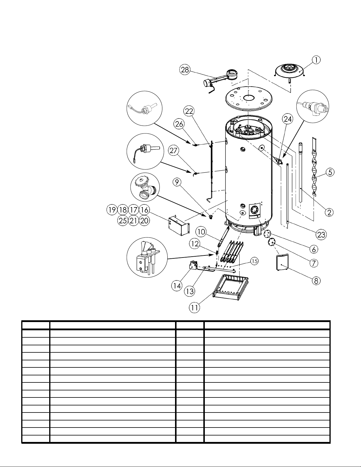
REPAIR PARTS ILLUSTRATION
When ordering repair parts always give the following information:
1. Model, serial, and product number
2. Type of gas
3. Item number
4. Parts description
Repair Parts List
24
No. Pa rt Name a nd De scri ption No. P art Name and Descri ption
1 Drafthood 16 Control B ox Cover
2 Diptube (Top) 17 Transformer
3 Diptube (F ront ) (Opt i onal not pict ured) 18 Igniti on Cont rol M odul e
4 Diptube (B ack ) (Optional not pi ct ured) 19 Thermost at board
5 Flue B affles 20 ECO Res et Board
6 Clean Out Gask et 21 Control B ox
7 Clean Out Cover 22 W i ring Harnes s
8 Clean Out Cover Jack et 23 Anode Rod(s )
9 Drain Valve 24 T&P Valve
10 Main Burner Tube(s) 25 Temp. Control P otent i om et er
11 Burner Tray 26 Upper Temperature Sensor/ECO
12 Pi lot B urner A s sem bl y 27 Lower Tem perature Sensor
13 Main Burner Manifold 28 Flue Damper
14 Gas Valve 29 Power Cord (Opti onal not pi ct ured)
15 Main Burner Orific e(s)

25
See Rating Label Serial Number prefix for
Warranty Code. Reduced warranty period
applies to Newfoundland.
Warranty Code: P R S T U V W Y
Standard Warranty Years: 3 5 6 7 8 9 10 12
Reduced Warranty Years: 233555 5 7
~ Certificate of Warranty ~
For its GSW and John Wood water heaters and storage boosters ("Unit"), GSW Water Heating ("GSW") warrants that, upon
receipt of a properly verified Warranty claim within the Warranty Period, it will, at its election, repair or replace: units which leak or parts which are defective
in material or workmanship, subject to the terms and conditions set forth in this certificate. GSW will not assume any expense or liability for unauthorized
returns, nor repairs made by a person who has not been authorized by GSW or one of its authorized dealers. GSW Units/parts must be replaced with GSW or
John Wood products to be eligible for Warranty. This W arranty is available to the original owner of a Unit installed within the boundaries of continental United
States, of Canada, or their territories. Consumers must retain point-of-sale proof of purchase to validate warranty entitlement. This Warranty does not
cover components not manufactured by GSW, such as oil burners, which carry the warranty given by the manufacturer thereof, copy of which warranty GSW
will make available, to the extent supplied by the manufacturer, without recourse to GSW.
THERE ARE NO WARRANTIES WHICH EXTEND BEYOND THE DESCRIPTION ON THE FACE HEREOF. THIS EXPRESS
WARRANTY IS, WHERE PERMITTED BY LAW, IN LIEU OF AND EXCLUDES AND REPLACES ALL OTHER CONDITIONS,
WARRANTIES, GUARANTEES, REPRESENTATIONS, OBLIGATIONS OR LIABILITIES OFGSW OFANY NATURE OR KIND,
EXPRESS OR IMPLIED, HOWEVER ARISING (WHETHER BY CONTRACT, CONDUCT, STATEMENT, STATUTE, NEGLIGENCE, PRINCIPLES OFMANUF ACTURER'S LIABILITY, OPERA TION OFLAWOR OTHERWISE) WITH RESPECTTO THE
UNIT OR ITS FITNESS FOR A PARTICULAR PURPOSE, MERCHANTABILITY, INSTALLATION, OPERATION, REPAIR OR
REPLACEMENT. GSW EXPRESSLY DISCLAIMS ANY AND ALLIMPLIED WARRANTIES. IN NO EVENT WILL GSW'S LIABILITIES EXCEED THE COST OF THE DEFECTIVE PART(S) OR UNIT. GSWWILLNOT PAY FOR ANYTRANSPORTATION,
LABOUR, INSTALLATION, OR OTHER INCIDENTAL COSTS ASSOCIATED WITH THE REPAIR OR REPLACEMENT OF A
DEFECTIVE PART OR UNIT.
This warranty and GSW's obligations shall be construed and determined in accordance with the laws of both the Province of Ontario, and of Canada in force
therein. This Warranty does not affect specific legal rights of a consumer under applicable law, except to the extent that such rights may be waived or replaced,
and the provisions hereof are deemed to be amended to the extent necessary. The unenforceability of any provision, in whole or in part, of this Certificate shall
not affect the remaining provisions. Any and all repair and/or replacement of part(s) or Unit are the sole and exclusive remedy available against GSW.
1. The Unit shall be installed in accordance with all manufacturers' instruc-
tions, all applicable equipment and building codes, ordinances and regulations (hereinafter referred to as the "standards").
2. The Unit must not be installed where water damage can result from a
leak, while provision(s) shall be made for directing any water escaping
from the Unit, to a properly operating drainpipe. As all units of this type
may eventually leak, you must protect against any potential water damage. GSW accepts no responsibility for such damage, nor any incidental
or consequential loss, nor damage(s) related thereto, suffered by the
owner of the Unit nor by any third party.
3. The Unit shall not be installed where it will be exposed to adverse or
unusual environmental or corrosive conditions. No warranty extends, for
example, and without limitation of the foregoing, to Units exposed to:
salts; chemicals; exhausts; pollutants or contaminants. Further, no warranty extends to Units affected by fire, freezing or flood, "Acts of God",
or any other contingency beyond the control of GSW.
4. The Unit shall be equipped with a properly operating temperature and
pressure relief valve as specified by GSW and applicable standards. The
Unit shall be operated at temperatures not exceeding the maximum setting of the thermostat and/or high limit control provided by GSW, and at
water pressures not exceeding the pressure reading stated on the Unit.
5. The Unit must be carefully inspected, maintained, and operated in accor-
dance with the manufacturer's instructions. No warranty extends, for
example, and without limitation of the foregoing, to any Unit operated:
without the tank being completely filled with water; without an operating
anode; with levels of sediment or lime precipitate which cause failure; in
connection to any attachment(s), energy saving device(s), or other means
of heating, except as approved by GSW for the Unit; other than with
potable water without any additives such as salts, chlorine or chemicals,
except those added for the sole purpose of rendering the water fit for
domestic use.
6. All repairs must be made by a competent and qualified person who is cer-
tified, by GSW or one of its authorized dealers, to work on the Unit, using
factory approved replacement parts, and the Unit shall not be otherwise
modified, altered or improperly repaired.
7. A properly documented claim shall be received by GSW or one of its
authorized dealers, or point of purchase, within the following Warranty
Period, except as provided otherwise below*:
a) for any defective part, within one (1) year; or
b) for any Unit that develops leaks in the inner tank due to rust, corrosion
or other chemical reactions caused by the potable domestic water supplied to your home, within the period of time shown in table at the top of
this page.
* Residential units installed and used in a commercial application carry a
warranty period of one (1) year from date of installation; and,
Any repair or replacement of any part, tank, or Unit under this Warranty
will not extend the Warranty Period beyond that calculated from the date
of first installation of the original Unit. The date of first installation will
be deemed to be the later of the date indicated by the Unit's serial number, or if supplied with the Warranty claim, the sales receipt, or installer's
receipt.
8. A claim under this Warranty must include the model and serial number of
the Unit, proof of date on which the Unit was first installed, and the identity of the defective part(s) for which a claim is being made and be submitted within 15 days following discovery of the defect(s), by personal
delivery to a GSW authorized dealer, point of purchase, or GSW itself at:
GSW Water Heating
GSW Water Heating is a division of GSW Water Products Inc.
599 Hill Street West
Fergus, ON Canada N1M 2X1
Should you have questions, please call our Technical Support Line at 1888-479-8324.
9. If requested by GSW, information relating to the purchase, transportation,
operation and installation of the Unit must be supplied. The defective
part(s) or Unit, with all components properly and securely packed, shall
be returned transportation pre-paid, to the address designated by GSW in
the written request. All claims are subject to validation by GSW.
LIABILITY OF GSW COVERED BY THIS WARRANTY IS CONDITIONAL UPON THE FOLLOWING:
 Loading...