

John Wood 324334-001 Installation And Operating Instructions Manual
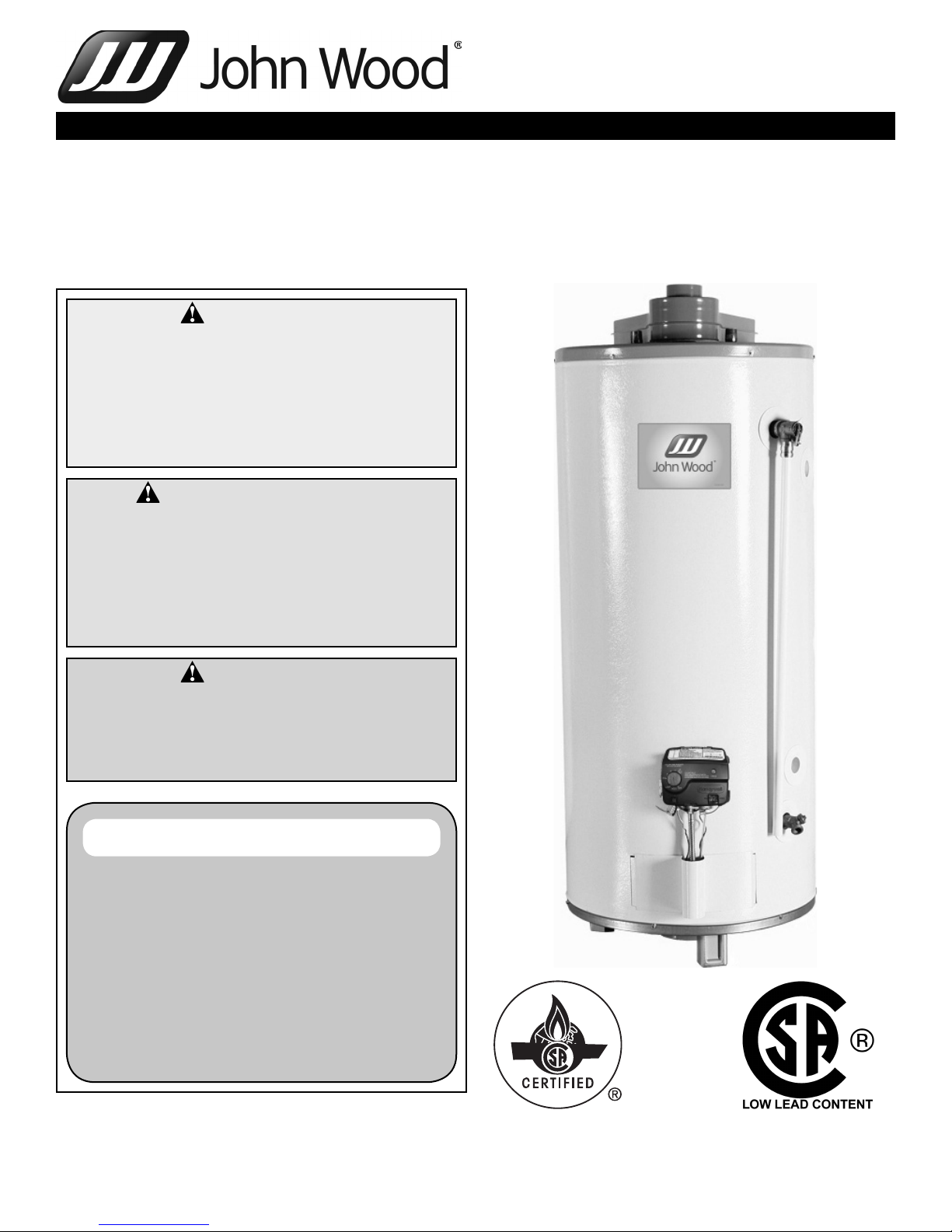
DIRECT VENT GAS FIRED WATER HEATER
WARNING:
Improper installation, adjustment, alteration, service, or maintenance can cause
injury or property damage. Refer to this
manual. For assistance or additional information, consult a qualified installer, service agency, or the gas utility.
FOR YOUR SAFETY
• Do not store or use gasoline or other
flammable vapours and liquids in the
vicinity of this or any other appliance.
• Installation and service must be performed by a qualified installer, service
agency or the gas utility.
INSTALLATION AND
OPERATING INSTRUCTIONS
Read these instructions thoroughly before starting
WARNING:
If the information in these instructions is
not followed exactly, a fire or explosion
may result causing property damage, personal injury or death.
WHAT TO DO IF YOU SMELL GAS
• Do not try to light any appliance.
• Do not touch any electrical switch; do
not use any phone in your building.
• Immediately call your gas supplier from
a neighbor’s phone. Follow the gas
supplier’s instructions.
• If you cannot reach your gas supplier,
call the fire department.
PART No. 324334-001 Rev. 00 (13-11)

TABLE OF CONTENTS
I) INTRODUCTION . . . . . . . . . . . . . . . . . . . . . . . . . . .3
Consumer Responsibilities 3
II) SAFETY . . . . . . . . . . . . . . . . . . . . . . . . . . . . . . . . . .3
Safety Warning (Flammable Vapours) 4
Safety Warning (Scalding) 4
Safety Warning (Carbon Monoxide) 4
Relief Valve Requirements (T&P) 4
III) INSTALLATION . . . . . . . . . . . . . . . . . . . . . . . . . . . . 5
Unpacking the Water Heater 5
Location 5
Venting 7
Vent connections
Offset vent pipe arrangement
High rise vent pipe arrangement
Vent Restricter Plate 9
Gas Connections 10
Gas Supply 10
Water Piping 10
Temperature & Pressure Relief Valve 10
The discharge line:
Closed system/Thermal expansion
Installation Checklist 11
IV) OPERATING INSTRUCTIONS. . . . . . . . . . . . . . . .12
Lighting instructions)
Special note on propane fuel:
Out of fuel
Water Temperature Regulation 13
Operating The Temperature Control System 14
Water temperature adjustment
Operating modes and settings
Exposure to water
Tampering
Status Light Code
V) MAINTENANCE INSTRUCTIONS . . . . . . . . . . . . .14
General Housekeeping 14
Tank 14
Venting System Inspection 14
Gas Control 14
Temperature & Pressure Relief Valve 15
Cathodic Protection 15
Burner Maintenance 15
VI) COMBO HEATING . . . . . . . . . . . . . . . . . . . . . . . . .16
VII) TROUBLESHOOTING GUIDELINES . . . . . . . . . .18
Status Light And Diagnostic
Code Troubleshooting Chart 20
LIMITED WARRANTY . . . . . . . . . . . . . . . . . . . . . .22
RETAIN THESE INSTRUCTIONS IN A SAFE LOCATION FOR FUTURE REFERENCE
– 2 –
Your safety and the safety of others is very important.
We have provided many important safety messages in this manual and on your appliance.
Always read and obey all safety messages.
This is the safety alert symbol.
This symbol alerts you to potential hazards that can kill or hurt you and others.
All safety messages will follow the safety alert symbol and either the word
“DANGER” or “WARNING”.
DANGER
Indicates an imminently hazardous situation which, if not avoided, will
result in death or injury.
WARNING
You can be killed or seriously injured if you don’t follow instructions.
All safety messages will tell you what the potential hazard is, tell you how to reduce the chance
of injury, and tell you what can happen if the instructions are not followed.
I) INTRODUCTION
Thank you for purchasing this water heater. Properly
installed and maintained, it will provide years of trouble free
service. This manual gives instructions for the proper installation, safe operation and maintenance of this water heater.
It is your responsibility to ensure that your water heater is
properly installed and cared for.
The warranty on this water heater is applicable only when
the water heater is installed and operated in accordance with
these instructions. The manufacturer of this water heater will
not be liable for any injury or property damage resulting from
failure to comply with these instructions. Protect your warranty: Regularly maintain your water heater as detailed in
the service and maintenance section of this manual.
This product is certified to comply with a maximum weighted
average of 0.25% lead content as required in some areas.
Service to the system should only be performed by a qualified service technician.
The manufacturer and seller of this water heater will not
assume any liability for any property damage, personal
injury or death resulting from improper sizing, installation or
failure to comply with these instructions.
The warranty on this water heater is in effect only when the
water heater is installed and operated in accordance with
these instructions. A data plate identifying your water heater
can be found above the gas control/thermostat. When referring to your water heater, always have the information listed
on the data plate readily available.
Protect your warranty: Regularly service your water heater
as directed in the "Maintenance" section of this manual.
Retain your original receipt as proof of purchase.
Consumer Responsibilities
This manual has been prepared to acquaint you with the
installation, operation and maintenance of your gas fired
water heater and provide important safety information in
these areas. It is your responsibility to ensure that your
water heater is properly installed and cared for.
FAILURE TO FOLLOW THE INSTRUCTIONS IN THIS
MANUAL MAY RESULT IN SERIOUS BODILY INJURY
AND/OR PROPERTY DAMAGE. THOROUGHLY READ
AND UNDERSTAND ALL INSTRUCTIONS BEFORE YOU
ATTEMPT TO INSTALL, OPERATE OR MAINTAIN THIS
HEATER.
Installation and service requires trade knowledge in the
areas of plumbing, electricity, venting, air supply and gas
supply. If you lack these skills or have difficulty understanding these instructions, you should not proceed. Enlist the
help of a qualified service technician to install this water
heater.
Examples of qualified service technicians include those
trained in the plumbing and heating industry, local gas utility
personnel or an authorized service person.
– 3 –
Do not discard this manual. You or future users of this water
heater will need it for reference.
II) SAFETY
This water heater is design-certified by CSA International as
a direct vented water heater.
In addition to the installation instructions found in this manual, the water heater must be installed in accordance with
all local and provincial or state codes or, in the absence of
such, with the latest editions of the following specifications.
“Natural Gas and Propane Installation Code” CSAB149.1 and “Canadian Electrical Code (CAN/CSA C22.1),
Part I” available from:
Canadian Standards Association,
5060 Spectrum Way,
Mississauga, Ontario, Canada
L4W 5N6
Check your phone listings for the local authorities having
jurisdiction over your installation.
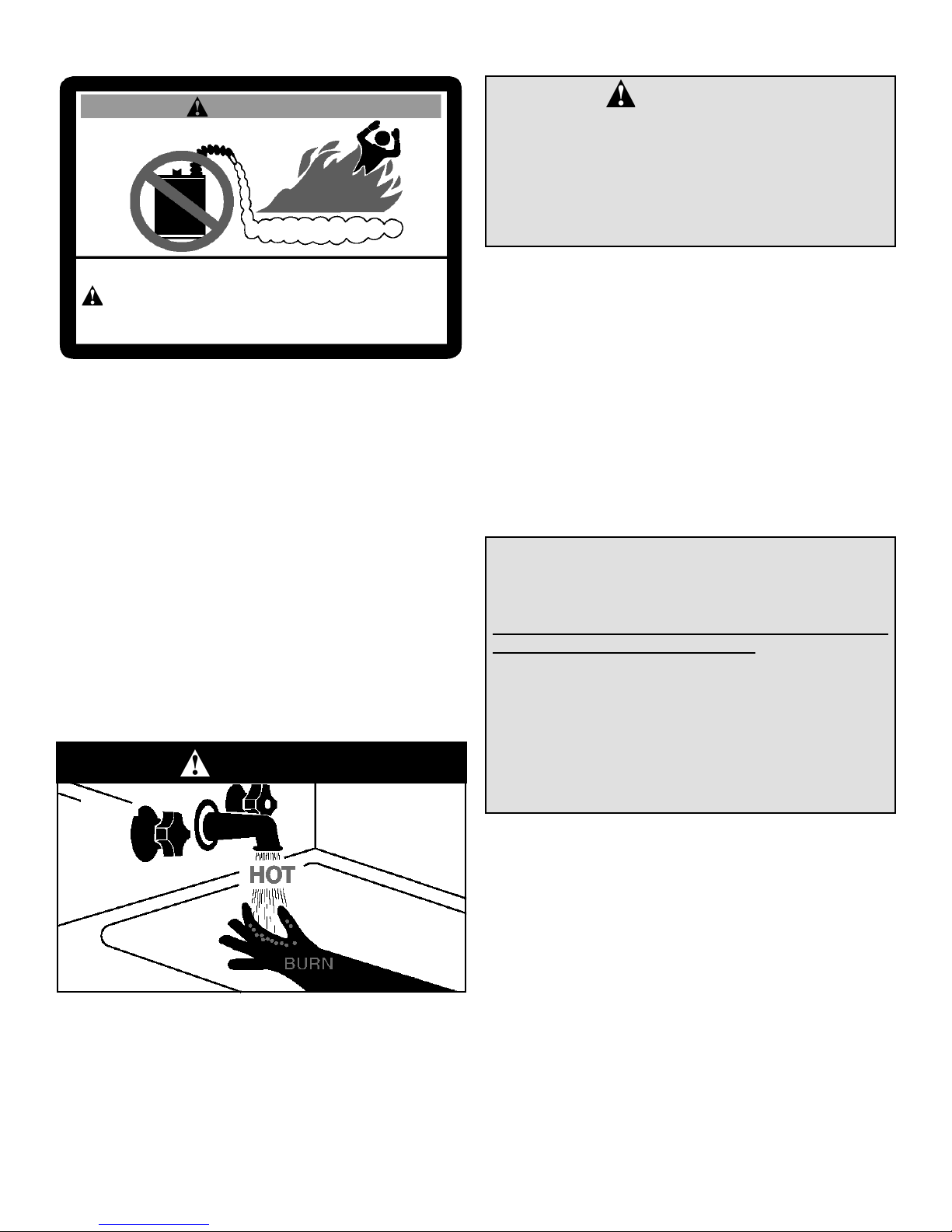
Safety Warning (Flammable Vapours)
Safety Warning (Carbon Monoxide)
WARNING
FLAMMABLES
FIRE AND EXPLOSION HAZARD
Can result in serious injury or death
Do not store or use gasoline or other flammable vapours and liquids
in the vicinity of this or any other appliance. Storage of or use of gasoline
or other flammable vapours or liquids in the vicinity of this or any other
appliance can result in serious injury or death.
There is a risk of property damage, personal injury or death
from the by-products of combustion (e.g., flue gases), in
using fuel-burning appliances such as water heaters. Areas
that may not be suitable for water heater installation include
those where flammable liquids, gasoline, solvents, adhesives etc. are stored, or where engine-driven equipment or
vehicles are stored, operated or repaired. These, and similar
products, should not be stored or used near the water heater
or air intake. Due to the nature of air movement, flammable
vapours can be carried some distance from the point of
storage. The gas-fired water heater igniter or burner flame
can ignite these vapours causing a flashback, fire or explosion, which may result in severe property damage, serious
personal injury or death. If flammable liquids or vapours
have spilled or leaked in the area of the water heater, leave
the area immediately and call the fire department from a
neighbor’s home. Do not attempt to clean the spill until all
ignition sources have been extinguished.
Safety Warning (Scalding)
Flammable Vapours
DANGER
DANGER
Carbon Monoxide Warning
• Follow all vent system requirements by
the local authorities having jurisdiction
over your installation.
• Failure to do so can result in death, explosion or carbon monoxide poisoning.
Relief Valve Requirements (T&P)
All water heaters must be fitted with a proper temperature
and pressure relief valve. These valves must be certified
as meeting the requirements of the “Standard For Relief
Valves For Hot Water Supply Systems, ANSI Z21.22/CSA
4.4”.
If this water heater has been exposed to flooding, freezing,
fire or any unusual condition, do not put it into operation until
it has been inspected and approved by a qualified service
technician.
THESE CONDITIONS CAN RESULT IN UNSEEN
INTERNAL DAMAGE and are not subject to warranty cov-
erage.
CAUTION
Hydrogen gas can be produced in a hot water system
served by this heater that has not been used for a
long period of time (generally two (2) weeks or more).
Hydrogen gas is extremely flammable and can ignite
when exposed to a spark or flame. To reduce the risk
of injury under these conditions, it is recommended that
the hot water faucet be opened for several minutes at the
kitchen sink before using any electrical appliance connected to the hot water system. Use caution in opening
faucets. If hydrogen is present, there will probably be an
unusual sound such as air escaping through the pipe as
the water begins to flow. There should be no smoking or
open flame near the faucet at the time it is open.
Hot water produced by this appliance can cause severe
burns due to scalding. The hazard is increased for young
children, the aged or the disabled when water temperatures
exceed 52°C (125°F). Use mixing valvess, also known as
mixing valves, in the hot water system to reduce the risk
of scalding at point-of-use such as lavatories, sinks and
bathing facilities. Such precautions must be followed when
this heater is operated in combination with dishwashing or
space heating applications.
– 4 –
III) INSTALLATION
Unpacking the Water Heater
WARNING
Excessive Weight Hazard
Use two or more people to move and install
water heater. Failure to do so can result in
back or other injury.
Important: Do not remove any permanent instructions,
labels, or the data label from outside of the water heater or
on the inside of panels.
• Remove exterior packaging and place installation com-
ponents aside.
• Inspect all parts for damage prior to installation and start-
up.
• Completely read all instructions before attempting to
assemble and install this product.
If you observe damage to the water heater or any of its components, DO NOT ASSEMBLE OR INSTALL IT OR MAKE
ANY ATTEMPT TO FIX THE DAMAGED PART(S). Contact
the place of purchase for further instructions.
• After installation, dispose of packaging material in the
proper manner.
IMPORTANT:
This water heater must be installed strictly in accordance
with the instructions enclosed, and local electrical, fuel
and building codes. It is possible that connections to the
water heater, or the water heater itself, may develop leaks.
IT IS THEREFORE IMPERATIVE that the water heater be
installed so that any leakage of the tank or related water
piping is directed to an adequate drain in such a manner
that it cannot damage the building, furniture, floor covering, adjacent areas, lower floors of the structure or other
property subject to water damage. This is particularly
important if the water heater is installed in a multi-story
building, on finished flooring or carpeted surfaces. THE
MANUFACTURER WILL NOT ASSUME ANY LIABILITY
for damage caused by water leaking from the water
heater, pressure relief valve, or related fittings. Select a
location as centralized within the piping system as possible. In any location selected, it is recommended that
a suitable metal drain pan be installed under the water
heater. This pan must limit the water level to a MAXIMUM
depth of 45mm (1 3/4 in.) and have a diameter that is a
minimum of 50mm (2 in.) greater than the diameter of the
water heater. Suitable piping shall connect the metal drain
pan to a properly operating floor drain.
Location
Generally, the location selected should be as close to the
wall as practical and as centralized with the piping system
as possible. Heater should be located in an area not subject
to freezing temperatures.
The water heater should be located so that the controls and
drain are easily accessible.
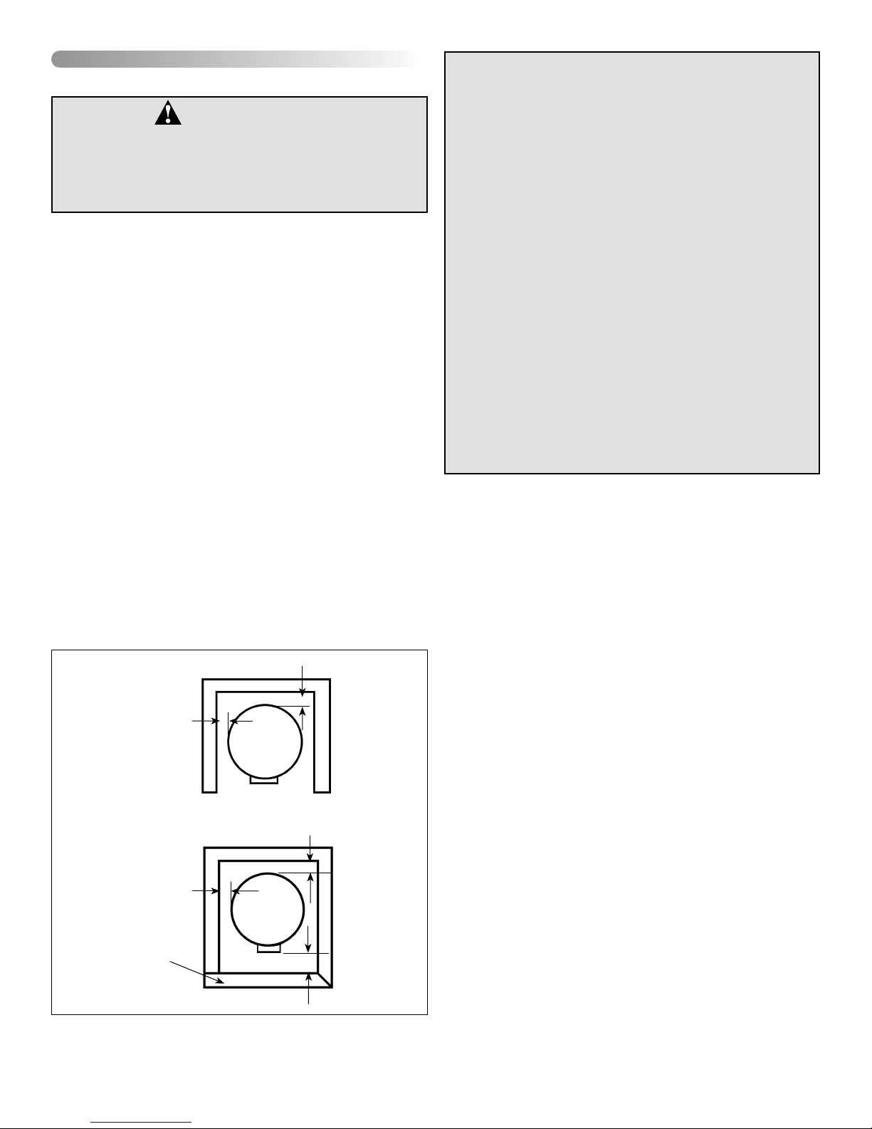
ALCOVE INSTALLATION
(TOP VIEW)
0mm (0 in.)
CLOSET INSTALLATION
(TOP VIEW)
0mm (0 in.)
0mm (0 in.)
0mm (0 in.)
CAUTION: When this water heater is installed directly on
carpeting, carpeting must be protected by a metal or wood
panel beneath the appliance extending beyond the full
width and depth of the appliance by at least 76mm (3 in.)
in any direction, or if the appliance is installed in an alcove
or closet, the entire floor must be covered by the panel.
The panel must be strong enough to carry the weight of the
heater when full of water. Failure to heed this warning may
result in a fire hazard.
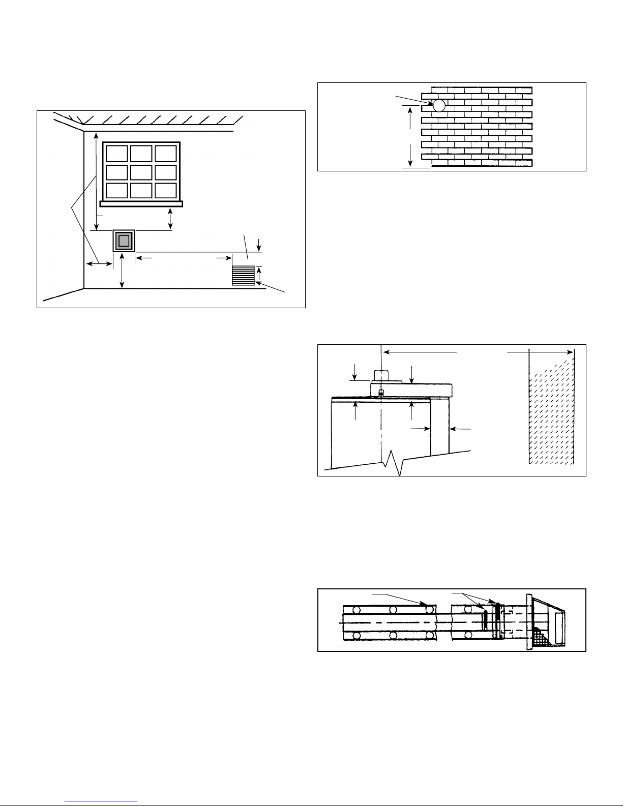
Minimum clearances between the heater and combustible/
non combustible materials are 0mm (0 in.) at the sides and
rear; 508mm (20 in.) from the top of water heater and 25mm
(1 in.) around the vent pipe. A minimum of 915mm (3 ft.) of
clearance is required at the front (control) side of the heater
for service.
For a closet installation, the door at burner side should be
openable and a minimum of 102mm (4 in.) clearance is
needed. Water heater is certified for installation on a combustible floor (see Figure 1).
CLOSET DOOR
Figure 1 Minimum Installation Clearances
– 5 –
102mm (4 in.)
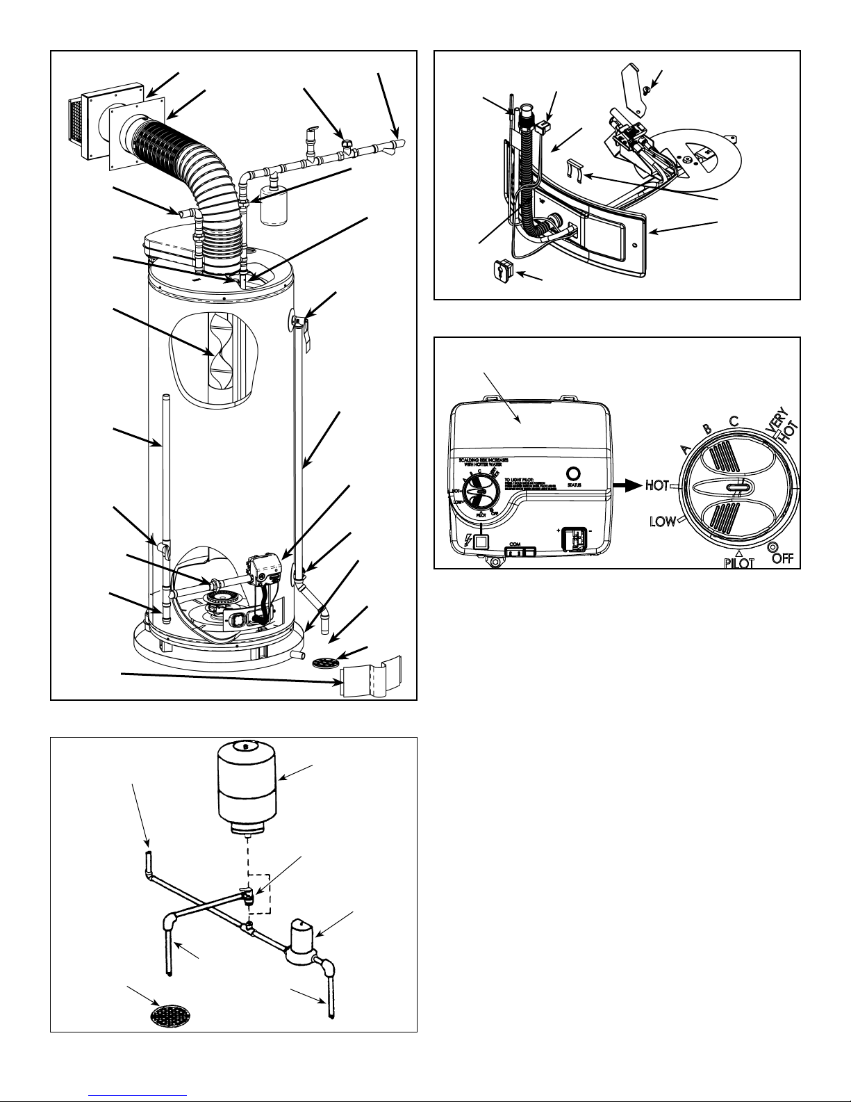
HOT WATER
OUTLET PIPE
ANODE
FLUE BAFFLE
GAS SUPPLY
LINE
MAIN MANUAL
GAS SHUTOFF
VALV E
TRIM PLATE
(OUTSIDE)
TRIM PLATE
(INSIDE)
INLET VALVE
COLD WATER
INLET PIPE
UNION
INLET DIP
TUBE
TEMPERATURE
AND PRESSURE
RELIEF VALVE
DISCHARGE PIPE
(DO NOT CAP OR
PLUG)
GAS CONTROL
VALV E/
THERMOSTAT
PILOT / THERMOPILE
PILOT
TUBE
IGNITER
WIRE
THERMOPILE
CONNECTOR
WHITE
WIRE
MANIFOLD
COMPONENT BLOCK
ASSEMBLY SCREW
Figure 2C - Installation Components.
List of status codes are shown
at top of gas control valve/thermostat.
RETAINER
CLIP
MANIFOLD
DOOR
BURNER AND OTHER
FITTINGS NOT
SHOWN FOR CLARITY.
GROUND-JOINT
UNION
SEDIMENT
TRAP (DIRT
LEG)
OUTER DOOR
Figure 2A - Installation Components.
WATER SUPPLY
TO HOME
DRAIN VALVE
METAL
DRAIN PAN
6” MAXIMUM
AIR GAP
FLOOR DRAIN
OPTION 2
EXPANSION TANK
OPTION 1
PRESSURE
RELIEF VALVE
WATER METER
WITH BACKFLOW
PREVENTER
Figure 2D - Installation Components.
Figure 2B shows the location of a pressure relief and/or
expansion tank if a check valve or pressure-reducing valve
is in the cold water supply to the house.
Use OPTION 1 or 2 whichever is more convenient. If pressure relief valve is used, select one with a setting 172 kPa
(25 psi) below the T&P valve rating at tank.
OVERFLOW
FLOOR DRAIN
WATER SUPPLY
TO METER
Figure 2B - Installation Options.
– 6 –
Venting
Make certain to observe the vent location limitations complying with the "Natural Gas and Propane Installation
Code" CSA-B149.1 or "National Fuel Gas Code" ANSI
Z223.1 (NFPA 54) and/or local codes. There is some impor-
tant information shown in Figure 3.
Vent connections
After the location for the vent terminal has been selected
as outlined in Figure 3, use the following illustrations for
installation:
178mm (7 in.)
DIAMETER
Vent Terminal must be located
at least 305mm (12 in.) from
Windows, Doors, or any other
Opening through which flue
gases could enter the building.
Vent terminal must
be located at least
915mm (36 in.)
above any Forced Air
457mm (18 in.)
Min.
305mm (12 in.) Min. above
Vent Terminal must be located at least 457mm
(18 in.) from any overhang or building corner
or other irregularity.
grade. Higher in Areas of
Heavy Snowfall
305mm
(12 in.)
Min.
Within 1.8m (6 ft.)
Inlet into the building
within 3m (10 ft.) of
the Vent Terminal
915mm
(36 in.)
Min.
Any Forced Air Inlet
into the building
Figure 3 - Vent Location Limitations
For a second or more direct vent unit, the distance between
vent terminals must have a minimum of 305mm (12 in.).
INSPECT SHIPMENT –– There may be hidden damage
caused by transit. Check to be certain all parts of the venting
system, as shown in Figures 3A through 3M, are present.
Inspect the upper and lower air inlet boxes, rear air tube and
all parts of the venting system (see Figure 2A).
CAUTION
If there are any damaged parts, DO NOT install this water
heater. Report any shortage to your distributor and damage
to your carrier.
MINIMUM
(SEE TEXT)
BOTTOM OF HEATER
Figure 3A - Locating Clearance Hole For Vent.
Cut a clearance hole, approximately 178mm (7 in.) in diameter, through the exterior wall for the vent assembly. The
minimum height should not be less than 1.72m (68 in.) for
40 gal. models and not less than 1.93m (76 in.) for 50 gal.
models, as measured from the hole center to bottom of
water heater. The maximum height recommended is 2.28m
(90 in.) or in compliance with Figure 3M.
* If the exterior wall is less than 356mm (14 in.) thick, the
clearance from the vent to combustible materials within
the hole can be 0mm (0 in.). If the wall thickness exceeds
356mm (14 in.), maintain a clearance of 25mm (1 in.) to
combustible materials within the hole.
102mm
(4 in.)
76mm
(3 in.)
432mm.
(17 in) MIN.,*
2.28m. (90 in)
MAX.
102mm
(4 in.)
WALL
Note: The four fasteners that are required to secure the vent
terminal to the exterior wall are not provided. These should
be screw type (not nails) chosen for the type of construction
and obtained locally.
Figure 3B - Moving Water Heater To Its Final Installed
Location.
Move the water heater to its final installed location. Make
certain clearances from combustible material are observed.
The maximum distance from center of water heater to out-
CAUTION
Cut edges of corrugated (flex) pipe are extremely sharp.
Wear gloves when handling.
side wall must not be more than 2.28m (90 in.).
* If the horizontal distance is less than 760mm (30 in.), the
restricter plate must be installed (see Figures 3N & 3O).
Figure 3C - Vent Assembly.
The vent pipe and terminal are assembled by the manufacturer as shown in Figure 3C. There are springs fastened
inside the corrugated pipe. When the vent pipes are pulled
to a required length, the distances between the springs will
still be equally spaced.
– 7 –
SPRING
CLAMP
 Loading...