

E.C.M. Issue - 707668
Print date - 05.10.2011
Maintenance
Section
VT551
Twin Engined
Suction Sweeper
With Mk II CANview Software
Stage 3a VM Engine
Part No 02634-1-M
Revision Level 02
Pneumatic System
Page Issue Levels
Scheduled Maintenance
Hydraulic System
Electrical System
Water System
11
Wearing Items
Remove and Refit Procedures
Fault Diagnosis
Service Tools
Warranty
Health and Safety
7
P
8
9
10
12
13
14
15
16
17
All Copyright and rights are the property of Johnston Sweepers Ltd

VT551 - Maintenance
All Copyright and rights are the property of Johnston Sweepers Ltd

Page Issue Levels
CHAPTER
P
Page Issue Levels
Description
This chapter lists each page in the Maintenance section, it’s issue level and
whether it has changed since the previous revision level. Changed pages are
indicated by the letter ‘C’ in the changed column, and new pages by the letter
‘N’.
P1
VT551 - Maintenance
Section Revision Level 02
All Copyright and rights are the property of Johnston Sweepers Ltd

Page Issue LevelsP2
P Chapter - Page Issue Levels
Page Issue Changed Page Issue Changed
P1 02 C P2 02 C
P3 02 C P4 02 C
7 Chapter - Scheduled Maintenance
Page Issue Changed Page Issue Changed
7:1 01 7:2 01
7:3 01 7:4 01
7:5 02 C 7:6 01
7:7 01 7:8 01
8 Chapter - Hydraulic System
Page Issue Changed Page Issue Changed
8:1 01 8:2 01
8:3 02 C 8:4 01
8:5 01 8:6 01
8:7 01 8:8 01
8:9 01 8:10 01
8:11 01 8:12 01
9 Chapter - Electrical System
Page Issue Changed Page Issue Changed
9:1 01 9:2 01
9:3 01 9:4 01
9:5 01 9:6 01
9:7 01 9:8 01
9:9 02 C 9:10 02 C
9:11 02 C 9:12 02 C
9:13 02 C 9:14 02 C
9:15 02 C 9:16 02 C
9:17 02 C 9:18 02 C
9:19 02 C 9:20 02 C
Section Revision Level 02
VT551 - Maintenance
All Copyright and rights are the property of Johnston Sweepers Ltd

10 Chapter - Water System
Page Issue Changed Page Issue Changed
10:1 01 10:2 01
10:3 01 10:4 01
10:5 01 10:6 01
10:7 01 10:8 01
10:9 01 10:10 01
10:11 01 10:12 01
10:13 01 10:14 01
11 Chapter - Pneumatic System
Page Issue Changed Page Issue Changed
11:1 01 11:2 01
11:3 01 11:4 01
11:5 01 11:6 01
11:7 01 11:8 01
11:9 01 11:10 01
12 Chapter - Wearing Items
Page Issue Changed Page Issue Changed
12:1 01 12:2 01
12:3 01 12:4 01
12:5 01 12:6 01
12:7 01 12:8 01
13 Chapter - Remove and Refit Procedures
Page Issue Changed Page Issue Changed
13:1 01 13:2 01
13:3 01 13:4 01
13:5 01 13:6 01
13.7 01 13.8 01
14 Chapter - Fault Diagnosis
Page Issue Changed Page Issue Changed
14:1 01 14:2 01
14:3 01 14:4 01
14:5 01 14:6 01
14:7 01 14:8 01
Page Issue Levels P3Section Revision Level 02
VT551 - Maintenance
All Copyright and rights are the property of Johnston Sweepers Ltd

Page Issue LevelsP4 Section Revision Level 01
VT551 - Maintenance
15 Chapter - Service Tools
Page Issue Changed Page Issue Changed
15:1 01 15:2 01
16 Chapter - Warranty
Page Issue Changed Page Issue Changed
16:1 01 16:2 01
16:3 01 16:4 01
17 Chapter - Health and Safety
Page Issue Changed Page Issue Changed
17:1 01 17:2 01
17:3 01 17:4 01
17:5 01 17:6 01
17:7 01 17:8 01
All Copyright and rights are the property of Johnston Sweepers Ltd

Chapter - Scheduled Maintenance
CHAPTER
7
Scheduled Maintenance
7:1
Table of Contents
Section Page
Introduction
Regular Maintenance 7 : 2
Security of Sweeping Equipment 7 : 3
Circuit Diagrams
Fluid Finder 7 : 4
Diagram Index 7 : 5
Auxiliary Engine
Fuel System Bleeding 7 : 6
Hydraulics
Hydraulic Oil Reservoir 7 : 7
Pneumatics
Filter Regulator Unit 7 : 8
Page Issue 01
VT551 - Maintenance
All Copyright and rights are the property of Johnston Sweepers Ltd
Page Issue 01Chapter - Scheduled Maintenance7:2
VT551 - Maintenance
INTRODUCTION
REGULAR MAINTENANCE
It is impossible to over emphasise the importance of regular maintenance, inspection and running
adjustments to maintain efficiency and obtain trouble free service from the machine.
Attention is drawn to the recommendation in the Auxiliary Engine Handbook relating to the post delivery
check over.
The maintenance schedule specified are for average operating conditions. Under particularly dry and
dusty conditions, it is essential that more frequent attention is given to:
1 Air cleaner servicing.
2 Engine oil changes.
3 Fluid oil changes.
4 Gearbox oil changes.
5 Hydraulic oil changes.
Attention to the servicing of air cleaners fitted to both auxiliary and vehicle engines is of vital importance
as clean air is essential for the proper functioning and ultimate life of an engine. Badly serviced air
cleaners can allow dust particles to be directly induced into the internal working surfaces with a resulting
rapid increase in engine wear and eventually complete failure. This also applies to any air leaks occurring
between the air cleaner and the engine inlet manifold. See separate instructions for Air Cleaner Servicing.
It is important that the following Safety Precautions are observed when working on the machine.
Ensure the machine is standing on firm, level ground and there are no obstructions above or
to the rear before raising the body.
Ensure the safety prop is used at all times when working under the body.
Ensure operators are fully conversant with the controls and operation.
Isolate the air in the filter regulator unit before working on any pneumatically operated or
controlled equipment.
Disconnect or isolate the vehicle battery when working on the electrical system.
Ensure the auxiliary engine is switched off once the channel brush has been lowered for
adjustment.
Be aware of the safety instructions relative to the suction fan given in the equipment
maintenance notes.
Keep hands, loose clothing, hair etc. well clear of moving parts.
Do not climb on the engine walkways unnecessarily or approach the fan inlet whilst the
engine is running.
Do not grasp any part of the engine or exhaust system without first ascertaining whether it
has cooled sufficiently to avoid scalding.
Do not use ill-fitting tools such as spanners that may slip and cause injury.
Use approved safety platforms/gantries when working above ground level. Get a
second person to check periodically when only one person is working on access
equipment or inside the body.
The use of ‘needle stick gloves’ is recommended when changing brushes, using the
wanderhose/Littasnatch and when cleaning out the machine.
Safety Precautions
All Copyright and rights are the property of Johnston Sweepers Ltd

Page Issue 01
Chapter - Scheduled Maintenance
7:3
VT551 - Maintenance
95MA. 024
ALTERNATIVE END MOUNTING POSITIONS
(HARDWARE AS PREFERED POSITIONS ie. ‘C’ and ‘D’)
‘A’ = M12 Standard ‘B’ = M12 Grade 10.9 ‘C’ = M14 Grade 10.9
‘D’ = M12, M14 Grade depending on chassis10.9 or M16 Standard
Torque Settings
M12 Standard = 95 Nm (70 lbf/ft)
M12 Grade10.9 = 135 Nm M16 = 235 Nm
M14 Grade 10.9 = 215 Nm (160 lbf/ft)
(100 lbf/ft) Standard (150 lbf/ft)
C
C
C
C
C
AA
D
D
D
D
CC
A
A
SECURITY OF SWEEPING EQUIPMENT
It is necessary to check every six months the security of various components as part of the maintenance
programme.
These fixings are detailed on the illustration below.
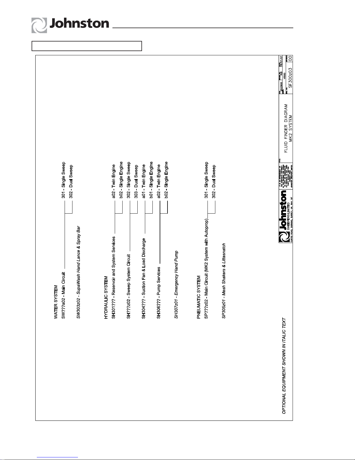
CIRCUIT DIAGRAMS
A chart can be found overleaf to assist in finding the circuit diagram required.
The actual circuit diagrams will be found in the appropriate chapter.
All Copyright and rights are the property of Johnston Sweepers Ltd
Page Issue 01Chapter - Scheduled Maintenance7:4
VT551 - Maintenance
Fluid Finder - Diagram SF300z03
All Copyright and rights are the property of Johnston Sweepers Ltd

Page Issue 02
Chapter - Scheduled Maintenance
7:5
VT551 - Maintenance
Diagram Index - SE300z01
All Copyright and rights are the property of Johnston Sweepers Ltd

Page Issue 01
Chapter - Scheduled Maintenance
7:6
VT551 - Maintenance
Please refer to the Operator’s Guide, Chapter 6, for the Routine Maintenance Schedules.
The following items are not covered in the Operator’s Guide.
MAINTENANCE AND ADJUSTMENT INSTRUCTIONS
AUXILIARY ENGINE - FUEL SYSTEM BLEEDING
Please refer to the Auxiliary Engine Handbook for information.
THROTTLE SETTINGS
The engine tick-over speed is adjustable and is set by the tick-over screw on the injector pump. The
engine maximum speed is controlled by the CANbus system and is not adjustable. The relevant speeds
are given in the chart below.
ENGINE
TYPE
JOHNSTON
PART NO.
IDLE
SPEED
Rev/min
MAXIMUM
FLIGHT SPEED
(Off Load)
Rev/Min
VM D754TE3
VM D754TE3
7015088 (12V)
7008519 (24V)
850
850
1800
1800
All Copyright and rights are the property of Johnston Sweepers Ltd

Page Issue 01
Chapter - Scheduled Maintenance
7:7
VT551 - Maintenance
Please refer to the Operator’s Guide Section 6 for the Routine Maintenance Schedules.
The following covers items not included in the above guide.
HYDRAULIC OIL RETURN FILTER
The filter should be changed every B Service, however there is an integral filter indicator on the side of
the filter head and, should this indicate red whilst the suction fan is operating, i.e. body raised, then the
filter is contaminated and requires changing at an earlier interval.
HYDRAULIC OIL RESERVOIR
Note: The filters can only be changed when the tank has been drained.
RENEWING THE RETURN FILTER
Unscrew cover (A) with a suitable spanner and lift out the cartridge element (B). Refit cartridge and screw
on the cover, some force will be required to compress the carriage retaining spring.
SYSTEM DRAINING
The oil can be drained by opening the tap
(G) and draining into a suitable receptacle.
RENEWING THE SUCTION FILTER
Change the filter whilst the system is empty.
The filter is changed as follows:
Remove the hydraulic hoses (D) to gain
access to the filter element (E). Replace
element and reassemble.
SYSTEM REFILLING
The system capacity dry is 80 litres. Refer to
Chapter 6 of the Operator’s Guide detailing
the correct oil level in the reservoir.
This should only be changed when the oil is cold, as the system could be
pressurised. Leave for 60 seconds after stopping for any pressure to be
dissipated before removing the return filter.
All Copyright and rights are the property of Johnston Sweepers Ltd

Page Issue 01Chapter - Scheduled Maintenance7:8
VT551 - Maintenance
FILTER REGULATOR UNIT
Comprises of a combined air filter/pressure regulator (A). It is mounted near the fan case on the right
hand side of the machine.
Safety Precautions
The shut off valve must be used when servicing any item on the air system
IN
A
B
C
D
CURRENT TYPE ‘A’ UNIT
(WITH SHUT OFF BALL VALVE ‘C’)
93MA. 017-2
The air filter unit incorporates a semi automatic drain which automatically dumps accumulated water when
the air supply is isolated by the shut off valve (C). It can also be drained by pushing up the drain tube (B)
that protrudes from the underside.
The pressure regulator (A) ensures the equipment is not over pressurised. It is factory set and sealed at
7
.
5 bar (108 psi).
A pressure switch (D) is fitted to illuminate the low air pressure warning lamp on the cab switch panel.
PNEUMATIC CYLINDER MAINTENANCE
Periodically inspect the cylinder rods for damage, blemishes or build up of material such as tar, cement,
paint etc. The rods can be cleaned with fine wire wool and/or spirit and should be kept clean to ensure
long seal life.
HYDRAULIC CYLINDER MAINTENANCE
Observe the notes on damage etc. described under pneumatic cylinders, especially with regard to the
wide sweep brush slewing cylinder on dual sweep machines and the channel brush lift cylinder.
Avoid playing the water washdown hose over the body tip cylinder when in the fully raised condition.
CLEANING THE VEHICLE
With the advent of high pressure steam and washdown equipment, damage can be caused by playing
this equipment onto the electrical control system, paintwork etc. and great care should be exercised when
it is carried out.
All Copyright and rights are the property of Johnston Sweepers Ltd

CHAPTER
8
Hydraulic System
Table of Contents
Section Page
Introduction
General Description 8 : 2
Circuit Pressures
Brushes 8 : 2
Water System 8 : 3
Suction Fan 8 : 3
Hopper Raise/Lower 8 : 3
Fan Pump Set Up 8 : 4
Hydraulic System
Initial Operation 8 : 5
Valve Identification 8 : 5
Circuit Diagrams
Hydraulic Tank Connections 8 : 6
Single Sweep 8 : 7
Dual Sweep 8 : 8
Suction Fan / Load Discharge 8 : 9
Pump Services 8 : 10
Emergency Hand Pump 8 : 11
Chapter - Hydraulic System
8:1
Page Issue 01
VT551 - Maintenance
All Copyright and rights are the property of Johnston Sweepers Ltd

Page Issue 01Chapter - Hydraulic System8:2
VT551 - Maintenance
GENERAL DESCRIPTION
The hydraulic system may be divided into four hydraulic circuits fed from a common hydraulic reservoir.
1 Sweep system.
2 Water system.
3 Fan drive system and load discharge.
Hydraulic filtration is provided by suction filters within the hydraulic tank, together with replaceable type ‘in
line’ return filter mounted externally on the upper face of the hydraulic tank.
CIRCUIT PRESSURES
Test points are provided on the hydraulic system to carry out pressure checks.
POINT NO. FUNCTION
T7 Sweep system test point
T8 Fan drive system/body discharge
T9 Water system (i.e. Supawash)
To set the hydraulic pressures select menu 4. Set
pressures from the main CANview screen and choose
sub menu 11.
NB : There is a default setting on this menu 4.11.6
to input default figures, in order for you to be able to
initially set the machine up and run the engine.
BRUSH PRESSURE - MENU 4.11.1
Connect a suitable 250 bar gauge to test point T7 (see
Valve Identification).
It is necessary to remove hose 201 in port C1 of the
‘sweep block 4’ and plug with a suitable plug and
also cap off the hose. Follow the on screen CANview
instructions.
This pressure should be 225 bar.
If necessary manually adjust RV1.
NB : DO NOT run the pressure test for longer than 30 seconds or damage maybe caused to the system.
93OG. 027-35
50%
14:00
25%4.0
93OG. 027-41
50%
14:00
25%
4.11
4.11
&
1 3 5
2 4 6
93OG. 027-36
50%
14:00
25%4.11.1
T7
C1
BLOCK 4
RV1
1800
n/min
All Copyright and rights are the property of Johnston Sweepers Ltd

Page Issue 02
Chapter - Hydraulic System
8:3
VT551 - Maintenance
WATER SYSTEM - MENU 4.11.2
Connect a suitable 250 bar gauge to test point T9.
Follow the on screen CANview instructions.
This pressure should be 220 bar. Remember to cap off
hose 206 when port W1 is plugged.
If necessary manually adjust RV2.
SUCTION FAN - MENU 4.11.3
Fit a 250 bar minimum pressure gauge to test point T8.
Follow the on screen CANview instructions.
This pressure should be 150 bar.
If necessary press + or - to adjust the pressure to 150 bar
± 5. Press to save setting.
HOPPER RAISE - MENU 4.11.4
Connect a suitable 250 bar gauge to Test Point T8.
Follow the on screen CANview instructions.
This pressure should be 175 bar.
If necessary press + or - to adjust the pressure to 175 bar
± 5. Press to save setting.
HOPPER LOWER - MENU 4.11.5
Connect test point as detailed above and follow the on
screen CANview instructions.
This pressure should be 80 bar.
If necessary adjust pressure by pressing + or -.
Press to save setting.
93OG. 027-37
50%
14:00
25%4.11.2
T9
W1
BLOCK 4
RV2
1800
n/min
93OG. 027-38
50%
14:00
25%4.11.3
T8
1800
n/min
+
-
+
-
RP
409MA
93OG. 027-39
50%
14:00
25%4.11.4
T8
1400
n/min
+
-
+
-
RP
348MA
93OG. 027-40
50%
14:00
25%4.11.5
T8
1400
n/min
+
-
+
-
RP
204MA
All Copyright and rights are the property of Johnston Sweepers Ltd

Page Issue 01Chapter - Hydraulic System8:4
VT551 - Maintenance
FAN PUMP
If the fan pump is changed it is necessary to check the pump pressure setting.
1. Standby - 20 bar.
*Run the auxiliary engine and measure the pressure on test point T8. The standby pressure should
be set at 20 bar.
2. Main Operating Pressure - 150 bar
To check this setting enter the suction fan pressure menu 4.11.3, follow on screen instructions and
increase RP output until the pressure reading on T8 remains the same. Ensure is pressed to save
the settings.
Please note that if the CANview node (node 3) is changed, the fan pump set up will need to be
re-checked.
All Copyright and rights are the property of Johnston Sweepers Ltd

Page Issue 01
Chapter - Hydraulic System
8:5
VT551 - Maintenance
HYDRAULIC SYSTEM INITIAL OPERATION
Start the auxiliary engine and open and close the rear door three times to ensure all air is purged from
the system.
Failure to carry out this procedure may cause the rear door lock to function incorrectly.
VALVE IDENTIFICATION
All Copyright and rights are the property of Johnston Sweepers Ltd

Page Issue 01Chapter - Hydraulic System8:6
VT551 - Maintenance
Hydraulic Tank Connections - Diagram SH301a02
All Copyright and rights are the property of Johnston Sweepers Ltd

Page Issue 01
Chapter - Hydraulic System
8:7
VT551 - Maintenance
Single Sweep - Diagram SH302z02
All Copyright and rights are the property of Johnston Sweepers Ltd

Page Issue 01Chapter - Hydraulic System8:8
VT551 - Maintenance
Dual Sweep - Diagram SH303z02
All Copyright and rights are the property of Johnston Sweepers Ltd

Page Issue 01
Chapter - Hydraulic System
8:9
VT551 - Maintenance
Suction Fan / Load Discharge - Diagram SH304a01
All Copyright and rights are the property of Johnston Sweepers Ltd

Page Issue 01Chapter - Hydraulic System8:10
VT551 - Maintenance
Pump Services - Diagram SH306a02
All Copyright and rights are the property of Johnston Sweepers Ltd

Page Issue 01
Chapter - Hydraulic System
8:11
VT551 - Maintenance
Emergency Hand Pump - Diagram SH307z01
All Copyright and rights are the property of Johnston Sweepers Ltd

Page Issue 01Chapter - Hydraulic System8:12
VT551 - Maintenance
All Copyright and rights are the property of Johnston Sweepers Ltd

Chapter - Electrical System
CHAPTER
9
Electrical System
9:1
Table of Contents
Section Page
Introduction
General Description 9 : 2
System Description 9 : 2
Component Identification
Relay Box 9 : 3
Relays/Fuses and Connector Refs. 9 : 4
Electrical Components Diagrams 9 : 9
Page Issue 01
VT551 - Maintenance
All Copyright and rights are the property of Johnston Sweepers Ltd

Page Issue 01Chapter - Electrical System9:2
VT551 - Maintenance
GENERAL DESCRIPTION
The system is integrated with that of the chassis in that it shares its battery and power source. The
auxiliary engine is equipped with a second alternator to supplement power generation. The system
activates all operational functions of the machine.
SYSTEM DESCRIPTION
The electrical system circuit diagrams are sub divided into modularised sub circuits and are identified
by an eight digit code, i.e. SE511Z01. The first five digits identify the machine and a particular control
feature, the last three digits identify variation and design status of the particular control feature. When the
sixth digit is a ‘Z’, then there is only one design variation, thought there could be other variations identified
by the seventh and eighth digits.
To assist fault finding and troubleshooting, the solenoids have an LED in the electrical connection plug
which illuminate when power is achieved.
RELAY/FUSE BOX
EP
FUSE RATINGS
F11
F12
F13
F14
F15
F1
F2
F6
F8
F10
10A RED
15A BLUE
15A RED
20A YELLOW
5A ORANGE
-
-
-
-
-
-
-
-
-
-
10A RED
20A YELLOW
15A BLUE
15A RED
15A BLUE
93MA. 012-3
MCB
MCB
30A
F1 F2
F13
F14
F15
F6 F8
(A)
F11
F12
F10
10A RED
15A BLUE
10A RED
20A YELLOW
5A ORANGE
10A RED
20A YELLOW
15A BLUE
10A RED
15A BLUE
12V 24V
ALWAYS turn OFF the truck ignition before changing / replacing fuses on the machine.
NEVER carry out welding on the machine without first disconnecting the two plugs on
Node 1 and Node 2 - failure to observe these procedures could damage the nodes.
All Copyright and rights are the property of Johnston Sweepers Ltd

Page Issue 01
Chapter - Electrical System
9:3
VT551 - Maintenance
The electrical system is protected by various fuses mounted in the relay box - See Operators Guide
Chapter 2.
The main feed from the battery to the electrical system is protected by a circuit breaker (MCB) which is
also mounted in the relay box.
The button (A) will pop out when activated and is ‘pushed in’ to reset when the fault has been cleared.
COMPONENT IDENTIFICATION
All Copyright and rights are the property of Johnston Sweepers Ltd

Relays
Ident. Description / Function Circuit(s) Ref. Location Notes
R1
Main Power Relay
Fuses 01-03
SE302 Relay Box
R2
Main Power Relay
Fuses 05-08
SE302 Relay Box
R3
Main Power Relay
Fuses 09-12
SE302 Relay Box
R4
Main Power Relay
Fuses 13-14
SE302 Relay Box
R5
Auxiliary Engine Cranking Power
Active with signal from CANView
SE302 Relay Box
R6
Beacon Power
Active with Beacon / Additional Beacon switch
SE302 Relay Box
R7 Not fitted
R8 Not fitted
R9
LH Worklamp Power
Active with Worklamp / Additional Worklamp switch
and Sweep Select Switch in LH or Dual mode
SE302 Relay Box
R10
RH Worklamp Power
Active with Worklamp / Additional Worklamp switch
and Sweep Select Switch in RH or Dual mode
SE302 Relay Box
R11
Battery Charge Changeover
Relay Box
R12
Additional Beacon Power
Active with Additional Beacon switch
SE302 Relay Box
R13
Additional Worklamp Power
Active with Additional Worklamp Switch
SE302 Relay Box
R14
Heat Start
Active with Heatstart Signal
SE302 Relay Box
Page Issue 01Chapter - Electrical System9:4
VT551 - Maintenance
Ref WD 227 issue 01
All Copyright and rights are the property of Johnston Sweepers Ltd

Page Issue 01
Chapter - Electrical System
9:5
VT551 - Maintenance
Ref WD 227 issue 01
Fuses
Ident. Description / Function
Rating (A)
12V/24V
Circuit(s) Ref. Location Notes
MCB Master Circuit Breaker 30/30 SE304 Relay Box
F01 Work Mode 10/10 SE304 Relay Box
F02 Auxiliary Engine Crank Solenoid 15/15 SE304 Relay Box
F03 Spare
F04 Spare
F05 Spare
F06 Additional Beacon 15/10 SE304 Relay Box Option
F07 Spare
F08 Node 2 20/20 SE304 Relay Box
F09 Spare
F10 Node 5 5/5 SE304 Relay Box
F11 Autolube, Cowl Work Lamp 10/10 SE304 Relay Box Option
F12 Node 1 20/20 SE304 Relay Box
F13 Worklamps 15/10 SE304 Relay Box
F14 Node 3 & Node 4 15/15 SE304 Relay Box
F15 Beacon 15/15 SE304 Relay Box
All Copyright and rights are the property of Johnston Sweepers Ltd

Page Issue 01Chapter - Electrical System9:6
VT551 - Maintenance
WD 227 Issue 01
Connectors - Numeric
Ident. No.Ways Location
Harness Ref.
(Female)
Harness Ref.
(Male)
P1 29 Relay Box 293716-1 293714-1
P2 31 Relay Box 293714-1 293717-1
P03
P04
P05
P06
P07
P08 12 Engine Bay 293719-1 293717-1
P09 4 Engine Bay 293719-1 293717-1
P10 8 Subframe – Rear 293718-2 293717-1
P11 8 Subframe – Rear 293718-3 293718-2
P12
P13
P14
P15
P16
P17
P18
P19
P20
P21
P22
P23
P24
P25
P26 2 Cowl 293775-1
P27
P28
P29
P30
All Copyright and rights are the property of Johnston Sweepers Ltd

Page Issue 01
Chapter - Electrical System
9:7
VT551 - Maintenance
WD 227 Issue 01
Connectors Alphanumeric
Ident. No.Ways Location
Harness Ref.
(Female)
Harness Ref.
(Male)
AL 2 Subframe – Autolube 293717-1
ALT-D 1 Auxiliary Engine – Alternator 293719-1
AR-1 4 Armrest Connector 293716-1 741928-1
AWB 2 Subframe – Additional Beacon 293717-1
AWL 2 Subframe – Additional Worklamp 293717-1
BEAC 5 Cab Beacon 293716-1
BEAC 2 Rear Beacon 293718-2
BEAC 2 Rear Beacon 293718-2
CAM 5 Camera Input 293716-1
CF 2 Chassis Fuel Tank 293717-1
CT 3 Subframe – CAN Terminator 293717-1
CVA 12 Switch Panel – CANView A 293716-1
CVB 12 Switch Panel – CANView B 293716-1
CVC 12 Switch Panel – CANView C 293716-1
CVD 17 Switch Panel 293716-1 293713-1
DAW 2 Front Valance – Discharge Buzzer 293726-1
DS1 2 Cowl Door – Limit Switch 293718-3
DS2 2 Cowl Door – Limit Switch 293718-3
ESC 2 Auxiliary Engine – Throttle Actuator 293719-1
ESOS 1 Auxiliary Engine – ESOS Valve 293719-1
ESS 3 Auxiliary Engine – Speed Sensor 293719-1
EWL 2 Engine Bay Worklamp 293717-1
F1 2 Fuel Tank #1 – Level Sensor 293717-1
F2 2 Fuel Tank #2 – Level Sensor 293717-1
FSS 3 Fancase – Fan Speed Sensor 293726-1
HOL 2 Hydraulic Tank – Oil Level 293725-1
HRW 2 Body – Hopper Raise Switch 293718-3
LA 2 FRL Unit – Air Pressure Switch 293717-1
LH-AWL 2 Body – Additional Worklight 293774-1
LMML 2 RH Cowl Door – Marker Light 293718-3
LRML 2 Rear of Body – LH Marker Light 293718-2
continues
All Copyright and rights are the property of Johnston Sweepers Ltd

Page Issue 01Chapter - Electrical System9:8
VT551 - Maintenance
WD 227 Issue 01
LWL 2 LH Work Lamp 293717-1
ML 2 Marker Lamp 293717-1
N1A 6 Node 1 – Power 293717-1 293725-1
N1 40 Node 1 – I/O 293725-1
N1B 12 Powapak 293717-1 293725-1
N2A 6 Node 2 – Power 293717-1 293726-1
N2 40 Node 2 – I/O 293726-1
N2B 8 Powapak 293717-1 293726-1
NP 2 Number Plate 293717-1
OPS 1
Auxiliary Engine –
Oil Pressure Sensor
293719-1
PCIA 17 Cab 293716-1
PEN 7 Cab 293716-1 283440-1
RH-AWL 2 Body – Additional Worklight 293774-1
RMML 2 RH Cowl Door – Marker Light 293718-3
RRML 2 Rear of Body – RH Marker Light 293718-2
RT 5 Auxiliary Engine – Heat Start Relay 293719-1
RWL 2 RH Work Lamp 293717-1
SM-S 1
Auxiliary Engine –
Starter Motor Solenoid
293719-1
SS 2 Connect for single sweep machines 293716-1 293716-1
VM4 4 Node 5 – Pneumatics 293717-1
VM5 5 Node 5 – Pneumatics 293717-1
WLI 2 Weight Load Indicator 293717-1
WTM 2 Water Tank – Mid Switch 293718-3
WTE 2 Water Tank – Empty Switch 293717-1
WTS 2
Auxiliary Engine –
Water Temperature Sender
293719-1
All Copyright and rights are the property of Johnston Sweepers Ltd

Electrical Components Diagram - SE300z02
Page Issue 02
Chapter - Electrical System
9:9
VT551 - Maintenance
All Copyright and rights are the property of Johnston Sweepers Ltd

Page Issue 02Chapter - Electrical System9:10
VT551 - Maintenance
Electrical Components Diagram - SE300z03
All Copyright and rights are the property of Johnston Sweepers Ltd

Page Issue 02
Chapter - Electrical System
9:11
VT551 - Maintenance
System Map Diagram - SE301z01
All Copyright and rights are the property of Johnston Sweepers Ltd

Page Issue 02Chapter - Electrical System9:12
VT551 - Maintenance
Relay and Fuse Box Diagram 24 Volt - SE302z01
All Copyright and rights are the property of Johnston Sweepers Ltd

Page Issue 02
Chapter - Electrical System
9:13
VT551 - Maintenance
Relay and Fuse Box Diagram 12 Volt - SE302z02
All Copyright and rights are the property of Johnston Sweepers Ltd

Chapter - Electrical System Page Issue 029:14
VT551 - Maintenance
Node 1 Diagram - SE303z01
All Copyright and rights are the property of Johnston Sweepers Ltd
Page Issue 02
Chapter - Electrical System
9:15
VT551 - Maintenance
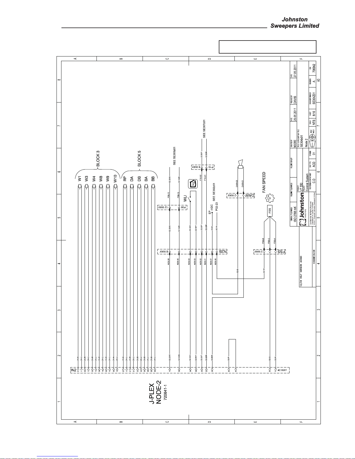
Node 2 Diagram - SE304z01
All Copyright and rights are the property of Johnston Sweepers Ltd

Page Issue 02Chapter - Electrical System9:16
VT551 - Maintenance
P1 CANview Diagram - SE305z03
All Copyright and rights are the property of Johnston Sweepers Ltd

Page Issue 02
Chapter - Electrical System
9:17
VT551 - Maintenance
P2 Subframe Diagram - SE306z02
All Copyright and rights are the property of Johnston Sweepers Ltd
Page Issue 02Chapter - Electrical System9:18
VT551 - Maintenance
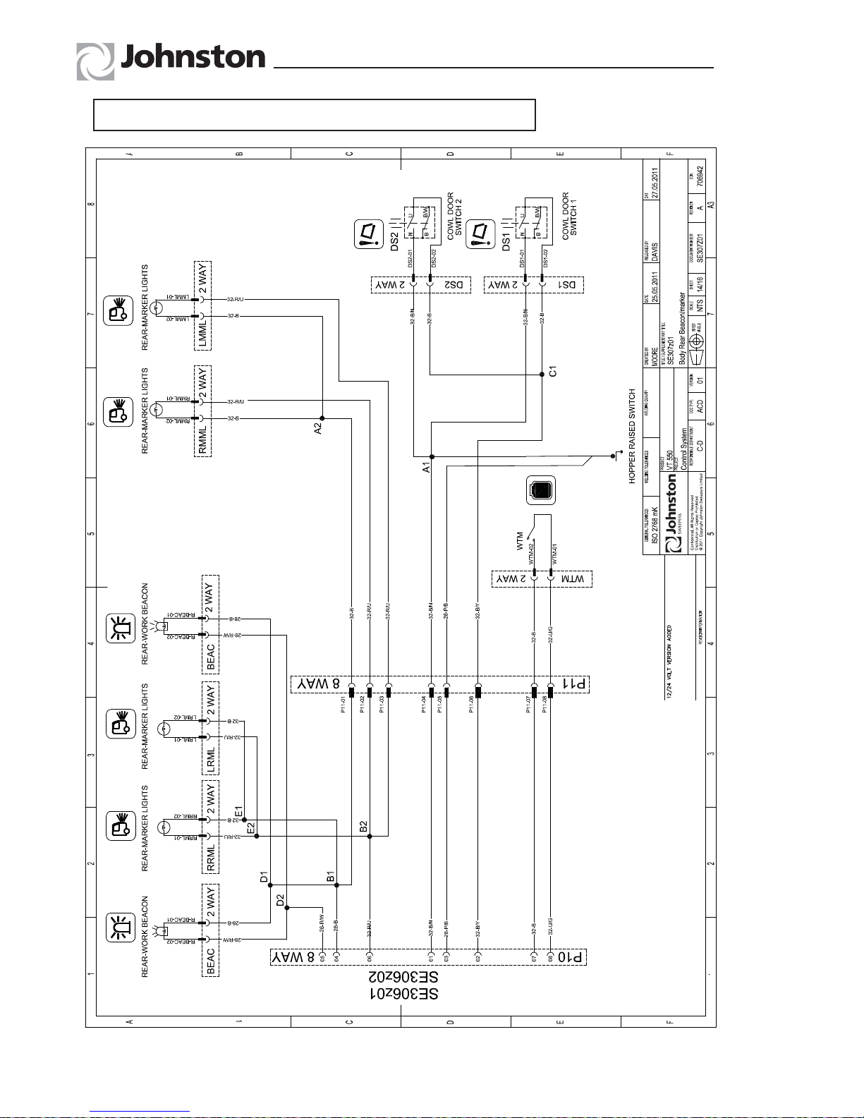
Body Rear Beacon / Marker Lamp Diagram - SE307z01
All Copyright and rights are the property of Johnston Sweepers Ltd

Page Issue 02
Chapter - Electrical System
9:19
VT551 - Maintenance
Switch Panel Diagram - SE308z01
All Copyright and rights are the property of Johnston Sweepers Ltd

Page Issue 02Chapter - Electrical System9:20
VT551 - Maintenance
VM Engine Diagram - SE309z01
All Copyright and rights are the property of Johnston Sweepers Ltd

Chapter - Water System
CHAPTER
10
Water System
10:1
Table of Contents
Section Page
Introduction
General Description 10 : 2
Supawash 10 : 2
Circuit Pressures 10 : 2
Component Maintenance and Settings
Relief Valve 10 : 3
Solenoid Valves 10 : 3
Hydrant Filter 10 : 3
Circuit Diagrams
Piping Diagram 10 : 4
Single Sweep Low Pressure Water 10 : 6
Dual Sweep Low Pressure Water 10 : 7
Supawash Pump
Pump Repair 10 : 9
Seal and Valve Maintenance 10 : 10
Exploded View of Pump 10 : 13
High Pressure Water Circuit Diagram 10 : 14
Page Issue 01
VT551 - Maintenance
All Copyright and rights are the property of Johnston Sweepers Ltd

Page Issue 01Chapter - Water System10:2
VT551 - Maintenance
GENERAL DESCRIPTION
Pressure for the water supply is provided by a piston pump hydraulically driven from the auxiliary engine.
Pressure regulation is by a relief valve situated at the rear of the machine. Filtration is by a in-line type
located at the right hand rear of the machine. An isolator valve is built into the in-line filter for ease of
element servicing. All sweeping spray jets are controlled by simple solenoid valves, manifold mounted on
the front of the engine tub.
Control of the washdown hose is by manual valves near the hose reel. The washdown hose is omitted
when high pressure water option is fitted.
SUPAWASH
This optional equipment comprises a hydraulically driven high pressure water pump, and a hand lance
mounted on the chassis with a 15 metre hose wound onto a recoiling reel.
Front and nozzle spraybars are optional equipment.
Supawash Unloader Valve - Pressure Setting
1. Ensure that the hydraulic relief valve has been set as outlined in section 8.
2. Fit a hydraulic test gauge to the Supawash manifold (T13).
3. Disconnect the 3/8” bypass pipe at the unloader valve and plug the hose end.
4. Turn on the front spraybar tap.
5. Activate the Supawash and increase the engine speed to 1800 rpm. Check to see if any water is
leaking from the bypass port on the unloader, if not loosen the retaining nut on the top of the unloader
and unscrew anticlockwise until water dribbles from the bypass port. Gently turn the adjuster clockwise
until water stops dribbling, then turn the adjuster 1/2 turn clockwise and lock off the retaining nut. The
operational pressure at the manifold should be 80-90 bar nominal. If the pressure is higher check again
for blocked jets. If the pump operates at a pressure in excess of 100 bar there is a problem that will effect
the life of the pump and invalidate any warranty.
NB - Do not turn off the front Supawash spraybar or water will be ejected from the bypass valve where
the hose has been removed.
6. Stop the engine and reconnect the bypass hose.
CIRCUIT PRESSURES
Two test points are provided for checking the water pressures.
Test Point No. Function
WTP Dust Suppression Sweep System
T13 Supawash System
All Copyright and rights are the property of Johnston Sweepers Ltd

Page Issue 01
Chapter - Water System
10:3
VT551 - Maintenance
RELIEF VALVE
This valve is factory set and should not normally be
touched, but should it be necessary to make adjustments,
the pressure is set as follows.
PRESSURE SETTING
Remove the cover (A) and loosen adjuster locknut (B).
Connect a pressure gauge to the test point located in the
systems locker. With the auxiliary engine running at low
idle speed (750/800), and all water sprays switched off,
turn adjuster screw (C) until gauge reads 3.5 bar (50 psi).
Tighten locknut and replace cover.
SOLENOID VALVES
Solenoid valves control the water spray jets and are
located on the front valance. Each valve incorporates a
filter (A) in its suction port and a manual lift override lever
(B). Turning the lever anticlockwise opens the valve;
clockwise closes it. This manual lift facility can be used
when draining the water system in winter (see Operator’s
Guide, Chapter 3) and for actuating the valve should it for
any reason fail to operate electrically.
The valve is readily dismantled for inspection or cleaning
by unscrewing the retaining cap (C) through the coil (D).
To access the armature, unscrew the four retaining screws
(E) and remove the armature cover (F). The armature (G)
can be removed. When refitting parts ensure the ‘O’ ring
(H) is in good condition and located correctly.
HYDRANT FILTER
Periodically the hydrant filler filter (A) should be cleaned,
or replaced if damaged. To gain access to the filter,
unscrew the hydrant coupling (B) and withdraw the filter
from its housing (C).
95MA. 021
95MA. 021
(A)
(A)
(C)
(C)
(B)
(B)
95MA. 020
95MA. 020
(C)
(C)
(A)
(A)
(B)
(B)
95MA. 019
95MA. 019
(C)
(C)
(D)
(D)
(B)
(B)
(H)
(H)
(E)
(E)
(F)
(F)
(G)
(G)
(A)
(A)
ON
ON
All Copyright and rights are the property of Johnston Sweepers Ltd

Page Issue 01Chapter - Water System10:4
VT551 - Maintenance
93MA. 011-4
DUAL SWEEP (D/S)
SHOWN
7
1
3
4
14
5
6
6
13
12
8
11
BLOCK 3
W1 W4 W3
WTP
W8 W9 W10
WTP
W1 W4 W3 W10
LH SINGLE
DUAL
WTP
W10 W3 W4 W1
RH SINGLE
WTP
16a16b
2
2
10
9
Piping Diagram - Low Pressure System
All Copyright and rights are the property of Johnston Sweepers Ltd

Page Issue 01
Chapter - Water System
10:5
VT551 - Maintenance
Illustration Component Key
1 Water tank
2 Tank overflow vent
3 Water pump - output 30 l/m
4 Unloader
5 Suction filter
6 Tank flushing ports
7 Tank filler port - hosepipe
8 Water level sight glass
9 Tank drain/flushing valve
10 Hydrant filler port for water tank
11 Type ‘A’ anti syphon water break
12 Relief valve
13 Washdown hose
*14 Additional wide sweep brush spraybar
Water valve manifold - see table below:
16a LH Water valve manifold
16b RH Water valve manifold
WTP Water test point
* Options
WATER VALVE STATION UTILISATION
*Options
S/S D/S VALVES WATER
VALVES LH RH SPRAYS
W1 W1 - Wide Sweep Brush Spraybar
W4 W4 W9 Nozzle (internal) Sprays
W3 W3 W8 Channel Brush and Gutter Sprays
W10 - W10 *Additional Spraybar
All Copyright and rights are the property of Johnston Sweepers Ltd

Page Issue 01
Chapter - Water System10:6
VT551 - Maintenance
Single Sweep Low Pressure Water - Diagram SW301a02
All Copyright and rights are the property of Johnston Sweepers Ltd

Page Issue 01
Chapter - Water System
10:7
VT551 - Maintenance
Water System Low Pressure Dual Sweep - Diagram SW302a01
All Copyright and rights are the property of Johnston Sweepers Ltd

Page Issue 01
VT551 - Maintenance
Chapter - Water System10:8
LP / HP Valve Location
All Copyright and rights are the property of Johnston Sweepers Ltd

Page Issue 01
Chapter - Water System
10:9
VT551 - Maintenance
Water Pump Repair
Water pumps by their very nature are subject to erosion and wear from the process of pumping water.
The life of the pump will depend on the quality of the water being used. The more particles that are in
suspension in the water the sooner the seals and valves in the pump will wear and require replacing and
are therefore considered as consumable items.
The main components in the pump that will require servicing are the suction and discharge valves and the
seals on the plunger pipes.
A pump working correctly will normally not have any water leaks. If the plunger seals wear water will leak
from the underside of the pump as shown below.
A drip ever 5 -10 seconds is an indication that the seals need replacing in the very near future.
A continuous drip from underneath the pump shows the seals are severely worn and require urgent and
prompt replacement. Shown by the arrows in the above picture.
If a steady stream of water leaking from the pump is observed the pump should NOT be used. Should the
pump be used in this condition water will be drawn back into the crankcase by the motion of the plungers.
This water ingress into the crankcase will cause a catastrophic failure of the pump.
When the suction and discharge valves wear the out put of the pump will be reduced and this will be
noticed as reduced output from the spray jets.
All Copyright and rights are the property of Johnston Sweepers Ltd

Page Issue 01Chapter - Water System10:10
VT550 - Maintenance
P22/34-100 Johnston Water pump 283701-1
Seal and Valve Maintenance Instructions
The following shows the overhaul procedure for the valves and plunger seals
1. With a 22mm socket,
remove the three discharge
valve plugs (43) from the
top of the manifold.
2. With a pair of needle nose pliers remove the spring
tension cap (34), spring (35) and plate (36)
3. Use a valve extractor
tool (99.061) to remove the
valve seats (37)
4. Inspect the valve seat
(37) and valve seat (36) for
signs of wear or cavitation
and replace as necessary.
5. Using an 8mm Allen key
remove the inner hexagon
screws (45)
6. With a rubber mallet tap
the back of the valve casing
(29) and pull the valve
casing (29) off the plungers
(24a).
7. Using a 6mm Allen
key remove the two inner
hexagon screws (46).
8. Separate the intermediate
casing (48) from the valve
casing (29)
All Copyright and rights are the property of Johnston Sweepers Ltd

Page Issue 01
Chapter - Water System
10:11
VT550 - Maintenance
9. Remove and inspect the
low pressure seal (50) and
replace if necessary.
10. Turn over intermediate
casting (48) Remove
and inspect the high
pressure seal (31) and the
support ring (32) replace if
necessary.
11. Remove the seal case
(39) from the valve casing
(29) and inspect both O
Rings (40) for wear.
12. Using needle nose
pliers, remove the spring
tensioning caps (34), valve
spring (35), valve plate (36)
from the valve casing (29)
Using a valve extractor
(99.061) to remove the
valve seat (37) from the
valve casing (29).
13. Inspect the valve seat
(37) and valve seat (36) for
signs of wear or cavitation
and replace as necessary.
14. Install the inlet valve
assembly (34 – 38) back
into the valve casing.
Ensure the “f ngers” of the
spring tensioning cap (34)
DO NOT obstruct the cross
bore in the valve casing
(29).
15. Install the seal case (39)
with O Rings (40) into the
valve casing (29)
16. Install the support ring
(32) and the high pressure
seal (31) into the intermediate plate (48)
17. Lubricate the low
pressure seal (50) and
install into the intermediate
casing (48).
All Copyright and rights are the property of Johnston Sweepers Ltd

Page Issue 01Chapter - Water System10:12
VT550 - Maintenance
18. Replace the three
spacer sleeves (26a) over
the plunger (24a) with the
f anged side toward the
valve casing (29)
19. Install the pressure
rings (30) over the plungers
(24a). Make sure that the
small o ring (49) is in place
in the intermediate casing
(49)
20. Secure the intermediate
casing (48) to the valve
casing (29) with the inner
hexagon screws (46).
Torque to 12 NM.
21. Place the valve casing
(29) over the plungers
(24a). Secure with inner
hexagon screws (45) Torque
evenly to 45 NM
22. Install the high pressure
valve assemblies with o
rings (34 – 38) Ensuring
the f ngers of the spring
tensioning cap (34) DO
NOT obstruct the cross bore
in the head (29).
23. Replace the high
pressure plugs (43) and
torque to 70 NM.
All Copyright and rights are the property of Johnston Sweepers Ltd

Page Issue 01
Chapter - Water System
10:13
VT550 - Maintenance
Exploded view of Pump
Item Number Quantity Part Number Description
19 1 283701-13 Woodruff Key
20 3 283701-14 Connecting Rod
24A 3 283701-12 Ceramic Liner
31,32,40,49,50 1 Kit 283701-10 Plunger Seal kit - for 3 plungers
34,35,36,37,38 1 Kit 283701-11 Valve Kit - for the 6 valves
All Copyright and rights are the property of Johnston Sweepers Ltd

Page Issue 01Chapter - Water System10:14
VT551 - Maintenance
High Pressure Water - Diagram SW303z02
All Copyright and rights are the property of Johnston Sweepers Ltd

Chapter - Pneumatic System
CHAPTER
11
Pneumatic System
11:1
Table of Contents
Section Page
Introduction
General Description 11 : 2
Circuit Pressures 11 : 2
Pneumatic Pipe Colours 11 : 2
Component Valve Identification 11 : 3
Component Removal
Air Filtration and Regulator (FR) 11 : 4
Pneumatic Valve Island 11 : 4
Wide Sweep Brush Regulator Maintenance 11 : 6
Circuit Diagrams
Maxigap Single Sweep 11 : 7
Maxigap Dual Sweep 11 : 8
Mesh Shakers and Littasnatch Option 11 : 9
Page Issue 01
VT551 - Maintenance
All Copyright and rights are the property of Johnston Sweepers Ltd
Page Issue 01Chapter - Pneumatic System11:2
VT551 - Maintenance
GENERAL DESCRIPTION
The air supply for the pneumatic system is taken from the vehicle braking system via a safety regulating
valve that ensures the braking system receives priority in the event of a failure to the sweeper air system.
Alternatively, where an air system is not available on the chassis air may be supplied by an electrically
driven air compressor system. A filter regulator unit with integral shut off/drain facility and low air pressure
warning buzzers are located near the fan case as are the electrical solenoid control valves for operation
of channel brush/nozzle and wide sweep brush. Wide sweep brush balance adjustment is provided by
pressure regulators.
CIRCUIT PRESSURES
A test point PTP (on piping diagram) is provided on the filter regulator unit (FR) to carry out pressure
checks, i.e. 8.0 bar (115 PSI).
The pressure in the Powathrust system is preset at 3.5 bar.
The pressure in the Powascrub system (option) is preset at 2 bar.
1 First ensure truck air system is up to pressure and sweepgear is lifted.
2 Fit a 25 bar minimum pressure gauge to test point PTP.
If pressure is incorrect, adjustment is carried out by turning the regulator control on the filter regulator unit.
NB : Provided on the (FR) unit is an air charge point (AC) via an airline push in connector supplied with
the sweeper.
PNEUMATIC PIPE COLOURS
A system of colour coding has been introduced to assist pipe identification and fault finding. The following
colours have been adopted.
R = Red - used for live feed/supply
U = Blue - used for switched supply via valve or tap
B = Black - used for permanent vent/exhaust line
Before servicing any components on this system, the air supply should be shut off by means of
the shut off valve mounted on top of the filter regulator unit. This not only severs the pneumatic
supply, it also exhausts the air from the system causing the nozzle and wide sweep brush to
lower. Wait approximately 15 seconds to allow air to completely exhaust before carrying out any
work. The shut off valve does not drain air from the vehicle braking system.
Safety Precautions
All Copyright and rights are the property of Johnston Sweepers Ltd

Page Issue 01
Chapter - Pneumatic System
11:3
VT551 - Maintenance
COMPONENT IDENTIFICATION
NODE 5
FR
R2
R3
R4
R5
93MA. 003
VM
V6V8V12V
14
V
2
V5V
7
V9V11V13V15V17V
19
V1V
3
V21V
23
V
20
V22V
24
B2
A1
A2 B1
R1
Regulators
A1 - B2 Wide Sweep Brush Balance - adjustable
R1 Channel brush Powasave - adjustable
R2 Wide sweep brush Powascrub - fixed
R3 Channel brush Powathrust (yellow) - fixed
R4 Left hand channel brush Kickback - adjustable
R5 Right hand channel brush Kickback - adjustable
FR Air filter regulator unit - see over page
All Copyright and rights are the property of Johnston Sweepers Ltd

Page Issue 01Chapter - Pneumatic System11:4
VT551 - Maintenance
AIR FILTRATION AND REGULATOR (FR)
A filter regulator unit, located near the fan case in the right hand side of the body, filters the air for the
sweeper section of the pneumatic system to prolong the life of the components served by it.
Before carrying out any major work on the unit, other than that described in the Routine Maintenance
Section of the Operator’s Guide, it will be necessary to remove it by first draining the vehicle air system,
then disconnecting the supply pipes and releasing the fixing bolts.
PNEUMATIC VALVE ISLAND
The pneumatic valve island is a modular unit comprising various valve segments. Each valve segment
has an indicator light that illuminates when energised (A) and a manual override button (B) for ports 2 or
4 on each segment
The segments are identified by a code and are not all the same - see following tables.
B
3
0
0
N
B
6
U
N
G
6
U
N
B
6
U
N
A
6
U
N
G
6
U
N
B
6
U
N
A
6
U
N
A
6
U
N
G
6
U
N
G
6
U
N
G
6
U
V21 23
V22 24
(H)
(G)
(F)
93MA. 004
VALV E
NUMBERS
OVERRIDE BUTTONS FOR
VALVES V2 - V24
OVERRIDE BUTTONS FOR
VALVES V1 - V23
DUAL SWEEP VALVE
WITH OPTIONS SHOWN
VALV E
NUMBERS
SEGMENT
CODES
(C)
(E)
(A)
(D)
(B)
(B)
12 - LAMPS FOR VALVES V2 - V24
14 - LAMPS FOR VALVES V1 - V23
V2 4 6 8 10 12 14 16 18 20
V1 3 5 7 9 11 13 15 17 19
To replace a valve segment -
1) Remove the 4 fixing screws (C).
2) Remove the 4 socket head screws (D).
3) Remove the valve cover containing the valve operating coils (E).
4) Unscrew (F) each side of the segment to be replaced.
5) Fold open the segment (G) and replace ensuring the rubber gasket (H) is in position.
6) Tighten screws (F).
7) Replace top cover (E).
8) Replace screws (D).
All Copyright and rights are the property of Johnston Sweepers Ltd

Page Issue 01
Chapter - Pneumatic System
11:5
VT551 - Maintenance
VALVE ISLAND PORT CONFIGURATION (VALVES NOT TICKED ARE REPLACED WITH B000)
VALVE
SEGMENT
CODE
* = T (12V)
* = N (24V)
PORT 4 / LED 14 PORT 2 / LED 12
293455-12
12V SINGLE
293455-24
24V SINGLE
293455-212
12V DUAL
293455-224
24V DUAL
V1 & V2 *G6U AUTOPROP EXTEND (NC) AUTOPROP RETRACT (NO)
3333
V3 *G6U CHANNEL BRUSH OUT LH (NC) CHANNEL BRUSH IN LH (NO)
3333
V5 & V6 *B6U V5 = CHANNEL BRUSH RAISE/LOWER LH (NO) V6 = NOZZLE RAISE/LOWER LH (NO)
3333
V7 & V8 *A6U V7 = MAXIGAP RH (NC) V8 = MAXIGAP LH (NO)
3333
V9 *G6U CHANNEL BRUSH OUT RH (NC) CHANNEL BRUSH IN RH (NO)
33
V11 & V12 *B6U V11 = CHANNEL BRUSH RAISE/LOWER RH (NO) V12 = NOZZLE RAISE/LOWER RH (NO)
33
V13 & V14 *A6U V13 = POWASCRUB (NC) V14 = POWATHRUST (NC)
3333
V15 *G6U FLAP LH FULL BORE (NC) FLAP LH ANNULUS (NO)
3333
V17 *G6U FLAP RH FULL BORE (NC) FLAP RH ANNULUS (NO)
33
V19 & V20 *A6U V19 = WSB BALANCE RH (NC) V20 = WSB BALANCE LH (NC)
33
V21 & V22 B300 BLANKED EXHAUST (5) BLANKED EXHAUST (3)
33
V23 & V24 *B6U V23 = WSB LOWER LH (NO) V24 = WSB LOWER RH (NO)
3333
REV REVISION INFORMATION
05
SLICE FOR V1 & V2 WAS BLANK
ED23490 - RD - 14/06/200704VALVE SLICE PREFIXES ADDED FOR 12V AND 24V
ED23384 - RD - 10/05/200703V19 & V20 REMOVED FROM -12 & -24, V23 & 24 ADDED TO -12 & -24
ED22500 - RD - 05/06/2006
REMOVE ALL BURRS AND SHARP EDGES.
DEV293
CANOpen
TITLE:SIMILAR TO:
MATERIAL:
930911
USED ON ASSEMBLIES:
283305
MASS (kg):
FINISH:
SEE DETAILS
1.13KG
AS SUPPLIED
VM10 PNEUMATIC VALVE ISLAND
SCALE:
DRG No:
1:2
02/12/2005
RD
MODEL:
DRAWN:
DATE:
REV.
A3
DRAWING STANDARDS TO BS 8888 WELD SYMBOLS TO EN 22553:1994 (ISO 2553:1991)
ALL DIMENSIONS SHOWN IN MILLIMETRES
COPYRIGHT IN THIS DRAWING AND DESIGN
IT IS AN INFRINGEMENT OF THE COMPANY'S
0.5° ANGULAR DIMENSIONS =
0.25 #.## AND HOLE DIAMETERS =
0.50 #.# AND ALL HOLE POSITIONS =
1.00
OF THE METRIC DIMENSION THUS:
ARE INDICATED BY THE DECIMAL PLACING
UNLESS OTHERWISE STATED, TOLERANCES
PROJECTION
293455
05
PROCESSING RESIDUE.
REMOVE ALL BURRS SHARP EDGES AND
CONSENT OF JOHNSTON SWEEPERS LTD.
TO ANY THIRD PARTY WITHOUT THE WRITTEN
TO COPY OR COMMUNICATE IT'S CONTENTS
#. EXCEPT MATERIAL THICKNESS =
DO NOT SCALE. IF IN DOUBT ASK.
Johnston
CURTIS ROAD, DORKING, SURREY RH4 1XF
SWEEPERS
A
100
53
202
VM1
VM2
78.5
V1 (4)
VIEW ON ARROW 'A' - SCALE 1:1
V5 (4)
V3 (4)
V7 (4)
V9 (4)
V11 (4)
V13 (4)
V21 (4)
V17 (4)
(2) V22
(2) V4
V19 (4)
(2) V6
(2) V8
(2) 10
(2) V12
(2) V14
(2) V16
(2) V18
(2) V20
(2) V24
(2) V2
(293455-212 & 293455-224 SHOWN ABOVE)
V15 (4)
PORT CONFIGURATION FOR VALVE ISLANDS - REFER TO TABLE BELOW
V23 (4)
Pneumatic Valve Island Configuration
All Copyright and rights are the property of Johnston Sweepers Ltd

Page Issue 01Chapter - Pneumatic System11:6
VT551 - Maintenance
WIDE SWEEP BRUSH REGULATOR MAINTENANCE
Before any work can be carried out on these units, they must be removed from their locations under the
ends of the subframe crossmember+ as follows.
Exhaust the system using filter regulator shut off valve, disconnect pipes from regulator and shuttle
valve, unscrew regulator securing nut. The regulator, shuttle and non-return valves can be removed as
a complete assembly.
REGULATOR
Remove the regulator by undoing the securing nut
(A). Use retaining ring pliers to remove the top plate
(6) and retaining ring (7). Pull cap (8) and ‘O’ ring (9)
from body.
Unscrew socket head screw (1), then remove button
(2), spring (3), knob (4), tumblers (5), couple (10) and
‘O’ ring (11).
Remove, as an assembled unit, the adjusting screw
(12) with upper and lower piston assemblies (Items 13
through 20). Remove spring (21).
Unscew the adjusting screw (12), then separate upper
and lower piston assemblies (Item 13 through 20).
The adjusting screw has left hand threads. Make sure
‘O’ ring (19) remains attached to the lower piston. If
not, retrieve it from inside the upper piston (13).
Unscrew bottom plug (22) to gain access to the parts
(23 through 36) located in the lower portion of the
body.
Clean and inspect each item for damage.
A repair kit, Part No. 253-10, is available comprising
Items 9, 11, 12, 14, 19, 20, 23-27, 29, 30 and 36.
When reassembling, lightly smear the ‘O’ rings and
rubbers with a silicon grease. Reassemble in the
reverse procedure.
PC. 0014
1
19
18
20
21
37
25
26
27
28
29
36
23
24
22
30
2
3
4
5
A
6
7
8
9
11
10
12
14
13
15
Make sure retaining ring (7) is fully seated in the groove in the body before
testing or refitting onto the machine.
All Copyright and rights are the property of Johnston Sweepers Ltd

Page Issue 01
Chapter - Pneumatic System
11:7
VT551 - Maintenance
Maxigap Single Sweep - Diagram SP301z02
All Copyright and rights are the property of Johnston Sweepers Ltd

Page Issue 01Chapter - Pneumatic System11:8
VT551 - Maintenance
Maxigap Dual Sweep - Diagram SP302z03
All Copyright and rights are the property of Johnston Sweepers Ltd

Page Issue 01
Chapter - Pneumatic System
11:9
VT551 - Maintenance
Mesh Shakers and Littasnatch Option - Diagram SP305z01
All Copyright and rights are the property of Johnston Sweepers Ltd

Page Issue 01Chapter - Pneumatic System11:10
VT551 - Maintenance
All Copyright and rights are the property of Johnston Sweepers Ltd

Chapter - Wearing Items
CHAPTER
12
Wearing Items
12:1Page Issue 01
VT551 - Maintenance
Table of Contents
Section Page
Replacement Instructions
Fan Impeller 12 : 2
Intake Duct Flap 12 : 3
Wear Plate 12 : 3
Intake Duct 12 : 4
Intake Trunking 12 : 4
Intake Seat 12 : 5
Suction Nozzle Wheel 12 : 5
Nozzle Wheel Bearings 12 : 6
Suction Nozzle Rubbers 12 : 6
Channel Brush 12 : 6
Wide Sweep Brush Fills 12 : 7
All Copyright and rights are the property of Johnston Sweepers Ltd

THESE ITEMS HAVE BEEN SPECIFICALLY DESIGNED FOR LO-NOISE EMISSIONS AND FITTING
OF ALTERNATIVE ITEMS COULD CAUSE AN INCREASE IN THE OPERATIONAL NOISE OF THE
MACHINE.
FAN IMPELLER
INSPECTION -This should be on a regular basis as outlined in the routine maintenance. The impeller
should be replaced as soon as the blade thickness is less than 2mm or the blades have visible signs of
wear/damage.
REMOVAL
1. Raise the body and ensure the body prop is
engaged in the rack.
2. Isolate the battery.
3. Remove the 12 bolts (A) holding on the fan
cover and remove cover (B).
4. Remove the capscrew (C) in the centre of the
fan.
5. The fan impeller should slide off the shaft, a
bearing puller 437-2 can be used if required.
Page Issue 01Chapter - Wearing Items12:2
VT551 - Maintenance
WEARING PARTS REPLACEMENT INSTRUCTIONS
It is important that the following safety precautions are observed when working on the machines.
Ensure the machine is standing on firm, level ground and there are no obstructions above or
to the rear before raising the body.
Ensure the safety prop is engaged at all times when working under the body.
Ensure operators are fully conversant with the controls and operation.
Isolate the air in the systems locker before working on any pneumatically operated or
controlled equipment.
Disconnect or isolate the vehicle battery when working on the electrical system.
Do not approach the fan inlet while the fan is running.
Do not grasp any part of the engine or exhaust system without first ascertaining whether it
has cooled sufficiently to avoid scalding.
Be aware of the safety instructions relative to the suction fan given in the equipment
maintenance notes.
Keep hands, loose clothing, hair etc. well clear of moving parts.
Do not climb on the engine walkways unnecessarily or approach the fan inlet whilst the engine
is running.
Do not use ill-fitting tools such as spanners that may slip and cause injury.
Always get a second person to check periodically that all is well when only one person is
working on the machine or inside the body.
Safety Precautions
93MA. 015-2
(A)
(B)
(C)
(D)
All Copyright and rights are the property of Johnston Sweepers Ltd

Page Issue 01
Chapter - Wearing Items
12:3
VT551 - Maintenance
REFITTING
1. Replacement is the reverse of removal.
2. Lightly grease the fan motor spline using grease part number 94-24 before fitting the impeller.
3. Fit a new Tuflok capscrew and torque up to 101 Nm (75lbf. ft.).
4. Refit fan case cover with a suitable silicone sealant between the mating surfaces.
From July 2009 all impellers have a ‘’V’’ mark (D) at Top Dead Centre (TDC) applied when they are
manufactured. When fitting a replacement impeller it should be rotated so this mark is at the 12 o’clock
(TDC) position before the retaining bolt is tightened to the prescribed torque.
INTAKE DUCT FLAP
When the flap plate is in the open position, it is abraded by the material
discharging from the intake duct into the body. The flap should be
inspected periodically and replaced when worn. To inspect one must
first open the rear door and suitably prop open, then depressurise the air
system in the systems locker, this will allow the flap to be opened and
closed manually from the interior of the body. Enter body and inspect
the flap valve plate which is secured to actuating fingers by a pair of
spring clips.
REMOVAL
To remove a flap plate the springs must be withdrawn using a suitable tool or bar. Notice how the springs
were fitted from each side of the finger guide and around the groove in the finger assembly. Once the
springs are removed the flap plate can be detached from the finger.
REFITTING
Before refitting or fitting a new flap plate, ensure the springs are in good condition and the finger adjustment
areas have been cleaned, then locate flap on the finger and replace springs. Ensure the flap plate seats
correctly on top of the inlet tube, if not, check for excessive wear on the inlet tube/flap, or adjustment of
the flap operating mechanism.
WEAR PLATE
REMOVAL
Enter the body after carrying out precautions as for intake
duct flap. The wear plate (A) is secured by two screws and
a clamp bar (B). It is a wise precaution to prop the wear
plate before attempting to remove these screws. Once the
screws are removed, support the wear plate and remove
the prop. Allow the wear plate to fall slightly and unhook
from the hooks (C) attached to the body outer skin, and
remove. Help may be required in removal as this unit weighs
approximately 36kg.
All Copyright and rights are the property of Johnston Sweepers Ltd

Page Issue 01Chapter - Wearing Items12:4
VT551 - Maintenance
INTAKE DUCT
These parts are also abraded by the material being conveyed from the suction nozzle and must be
periodically inspected and replaced when worn or holed. The duct is 250mm diameter.
REMOVAL
Enter body after carrying out the same precautions as for
intake flap replacement. Remove the four bolts securing
the collar (A) around the intake duct (B). Lift up the flap
manually (if fitted) and remove collar. A rubber cord (C)
will now be visible which should also be removed with care
to prevent damage. Dismount from body. Tip body and
support on prop. Remove the four bolts in the square flange
carrying the flexible trunking seat seal (D). The intake duct
can now be pulled downwards clear of the body.
REFITTING
Reverse of removal procedure, but if fitting a new duct a
new trunking seat seal should be used and secured using a
contact adhesive, Part No. 9903. Fit two bolts in diagonal
holes, the duct (B) has two holes with keyhole slots. Align
slots over the bolt heads and twist. Fit the other two
bolts and tighten. The rest is the reverse of the removal
instructions. Replace the rubber cord (C) and collar plate
(A) inside the body and secure. Finally, fully tighten the four
duct top retaining bolts.
NB : Torque for brass M12 bolts 22 Nm (25ft. lbf.).
FLEXIBLE INTAKE TRUNKING
REMOVAL
Lower suction nozzle to the ground, release worm drive clips at either end and remove trunking. The
nozzle trunking has an inside diameter of 250mm.
REFITTING
Loosely fit worm drive clips to either end of trunking. Engage trunking onto the nozzle with a 55mm (2”)
overlap and tighten clip. Fit other end to the intake seat and secure. Check trunking is not twisted or
rucked and does not foul anything when the nozzle is raised or lowered again.
All Copyright and rights are the property of Johnston Sweepers Ltd

Page Issue 01
Chapter - Wearing Items
12:5
VT551 - Maintenance
INTAKE SEAT
REMOVAL
Firstly tip body and support on prop. Release trunking from tube
as described on previous page. Release and remove the three
countersunk screws and nuts (A). Lift seat (B) clear of bracket.
REFITTING
Reverse of removal procedure. As no adjustment for seal
compression is provided, it is wise to check seal compression
when the body is lowered.
Note : When replacing the intake seat, it is important that the
correct length is used. The correct length of intake seat is
determined by measuring dimension A, as shown below,
from ground to underside of the subframe (i.e. top of
chassis).
SUCTION NOZZLE WHEEL
REMOVAL
Release nozzle wheel adjustment nut (A) on inner end of wheel spindle. Remove wheel complete.
REFITTING
Reverse of removal procedure.
TYRE - SUCTION NOZZLE WHEEL
REMOVAL
Remove nozzle wheel as above. Remove
five screws securing tyre plate (B) and prise
off. Remove tyre from hub.
REFITTING
Reverse of removal procedure.
Note : Ensure correct re-setting of nozzle rubbers in relation to the ground.
Dimension A
Inlet Seat
Part No. ‘B’
900 - 999
1000 - 1099
1100 - 1199
94990-1
94990-3
94990-4
All Copyright and rights are the property of Johnston Sweepers Ltd

Page Issue 01Chapter - Wearing Items12:6
VT551 - Maintenance
NOZZLE WHEEL BEARINGS
REMOVAL
To withdraw bearing remove wheel assembly from carriage and remove the three setscrews from the
retaining plate. Refit washer and nut, insert M6c x 50mm setscrews, Part No. 124-113, in the three unused
retainer plate holes. Tighten each bolt half a turn at a time to extract the bearing. Remove drift bearing
from shaft.
REFITTING
Reverse of removal procedures.
SUCTION NOZZLE RUBBERS
REMOVAL
This can be effected without removing the nozzle assembly from the machine but if personnel are
inexperienced it will probably be easier to remove nozzle assembly and turn upside down. Release two
screws retaining bump bar at kerb end of nozzle. Release securing nuts retaining the rubbers. Pull away
the two short end rubbers, then remove the front and rear side rubbers.
REFITTING
Reverse of removal procedure remembering to fit the radius rubber to the nozzle rear. Do not over tighten
the nuts as this will cause distortion of the rubber. Refit bump bar.
CHANNEL BRUSH
REMOVAL
It is preferable to have brush in working position with auxiliary engine stopped. Release four nuts from
coach bolts securing brush stock assembly drive plate. Remove brush.
REFITTING
Reverse of removal procedure. Any loops of steel tines which project above the head of the stock should
be hammered flush before offering up brush stock assembly to driving plate.
WIDE SWEEP BRUSH CORE ASSEMBLY
See Chapter 6 in the Operator’s Guide.
Sharp objects
Sharp objects
All Copyright and rights are the property of Johnston Sweepers Ltd

Page Issue 01
Chapter - Wearing Items
12:7
VT551 - Maintenance
Replaceable Segment Option
REMOVAL
Release and remove the retaining screws (F) securing the end plate / adaptor (A). Slide off the segments
(B) and spacers (C) from the central core. Note : On earlier machines the driving pin (E) on the inner
diameter of the segments must be aligned with a slot (D) on the core (G) where the two parts join.
REFITTING
First slide on a segment then alternately a spacer and a segment. Sufficient spacers and segments must
be fitted to allow the end plate to nearly abut with the core and also clamp them tightly. The peg (E) on
the segment (B) to be alternatively located round the core clock face at 12, 2, 4 o’clock and so on until
the core is filled, failure to observe this could cause the brush to bounce. The last segment must have the
pin (E) on the segment (B) located in the cut out (D) to ensure the peg does not interfere when the parts
are bolted together.
Note : Lightly smear the retaining screws (F) with grease.
This assembly is designed to accommodate 340mm diameter segments.
Plastic Throw Away Stock
The stock (H) is removed and can be recycled as plastic waste.
WIDE SWEEP BRUSH FILLS
There are two types of brush fills:
a) Plastic ‘throw away’ stock tines.
b) Replacement segments.
All Copyright and rights are the property of Johnston Sweepers Ltd

Page Issue 01Chapter - Wearing Items12:8
VT551 - Maintenance
All Copyright and rights are the property of Johnston Sweepers Ltd

Chapter - Remove and Refit Procedures
CHAPTER
13
Remove and Refit Procedures
13:1
Table of Contents
Section Pages
Removal and Refitting Instructions
Water Pump 13 : 2
Wide Sweep Brush Motor 13 : 2
Channel Brush Motor 13 : 3
Channel Brush Cylinder 13 : 3
Body and Body Tip Ram 13 : 4
Radiator 13 : 5
Hydraulic Pump 13 : 5
Fan Impeller 13 : 5
Fan Case and Fan Motor 13 : 6
Fuel Tanks 13 : 7
Engine Actuator 13 : 7
Page Issue 01
VT551 - Maintenance
All Copyright and rights are the property of Johnston Sweepers Ltd

Page Issue 01Chapter - Remove and Refit Procedures13:2
VT551 - Maintenance
This section describes the removal and refitting of some of the major components on the machine. These
are not routine jobs and should normally only need to be undertaken when overhauling or exchanging
these units.
1. WATER PUMP - REMOVAL AND REFITTING
1. Isolate the water supply at the filter unit.
2. Mark up the position of the water and hydraulic feed
and return pipes before disconnecting. It will be
necessary to cap the hydraulic pipes to prevent oil loss.
3. Remove the 4 bolts (A) holding the pump brackets to
the centre subframe crossmember.
4. Refit in the reverse order.
5. Turn on the water at the filter and run pump to check for
water and hydraulic leaks.
NB - It is possible to replace the pump suction and discharge
valves in situ.
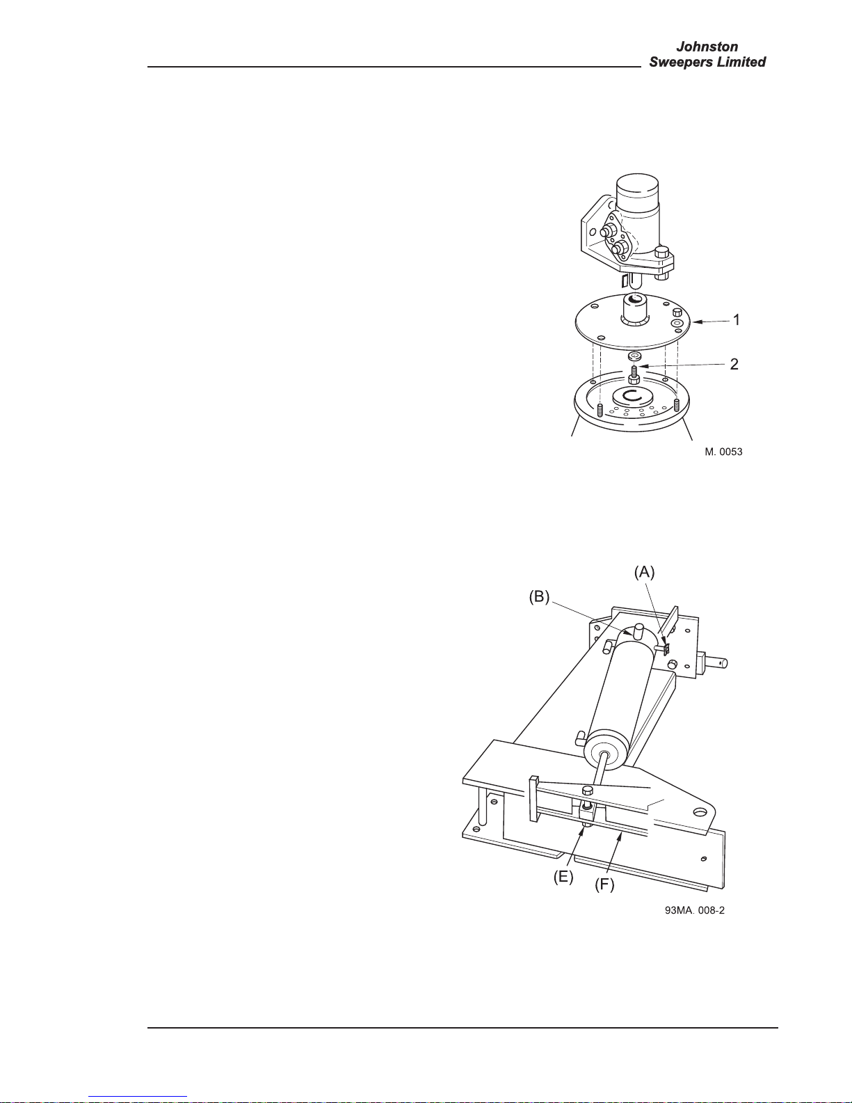
2. WIDE SWEEP BRUSH MOTOR - REMOVAL AND REFITTING
1. Remove the brush stock as described in Chapter 6.
2. Unscrew the four end plate securing setscrews and remove plate complete with motor assembly and
drive shaft or drive dog.
FIGURE 4 - WIDE SWEEP BRUSH
MOTOR
1. End plate securing screws.
2. Drive shaft retaining screws.
3. Drive shaft/drive dog.
4. Retaining plate.
5. Drive adaptor retaining screw.
6. Drive adaptor
7. Motor securing screws
The hinged prop stowed beneath the body SHOULD BE USED AT ALL TIMES to prop the body
when carrying out any inspection, servicing or maintenance work beneath the body.
Disconnect or isolate the battery before undertaking any of the following operations
on the sweeper and remove the chassis ignition key to isolate the power units.
Safety Precautions
93MA.018
A
All Copyright and rights are the property of Johnston Sweepers Ltd
Page Issue 01
Chapter - Remove and Refit Procedures
13:3
VT551 - Maintenance
3. CHANNEL BRUSH MOTOR - REMOVAL AND REFITTING
1. Unscrew the four nuts (A) from the coach b olts
securing the channel brush to the drive adaptor plate
and remove brush.
2. Unscrew the retention screw (B) from the centre of the
drive adaptor plate and remove plate. A special tool,
Part No. 48094-1, is available for this purpose.
3. Disconnect the two hydraulic hoses from the motor.
4. Unscrew the two bolts securing the motor to mounting
bracket and lift off motor.
5. Refitting is the reverse of removal.
4. CHANNEL BRUSH CYLINDER - REMOVAL AND REFITTING
1. Isolate air supply at FR unit.
2. Disconnect the 2 air hoses from the rear.
3. Remove clip on pin (A) and push through.
4. Remove pin (B) by pushing through.
5. Remove cylinder eye pivot bolt (E) from the
lever pivot head (F).
6. Refit is reverse.
7. Grease items (E) and (B) prior to refitting.
All Copyright and rights are the property of Johnston Sweepers Ltd

Page Issue 01Chapter - Remove and Refit Procedures13:4
VT551 - Maintenance
5. LIFTING OR REMOVAL OF THE BODY
If it is necessary to raise the body, 2 holes are
provided in the front of the body.
Remove blanking bolts (A).
Insert eye bolt item (B) part no. 422-1 into the
M16 socket.
If the body has to be removed use the two lifting
eyes and point (C) with a suitable chain or web
strap.
6. BODY TIP RAM - REMOVAL AND REFITTING
1. Raise the body and rest on the body
prop, which should be set on the lowest
notch.
2. Fit brackets 293909-1 to the subframe
crossmember and the front of the body.
Secure each with two M12 x 30 bolts
plus washers and nuts.
3. Raise the body a little and get an
assistant to place the special workshop
prop 293856-1 between the two brackets.
Insert pins (A) through the holes in the
brackets and prop and retain with the ‘R’
clips.
4. Stop the auxiliary engine. Remove truck
ignition keys to isolate the unit.
93MA. 009-2
Before the body tip ram can be removed it is necessary to fit the special workshop
retaining prop KT 01893 to ensure the body does not tip over when the ram is removed.
93MA. 013-2
293909-1
293909-1
293856-1
(A)
(A)
All Copyright and rights are the property of Johnston Sweepers Ltd

Page Issue 01
Chapter - Remove and Refit Procedures
13:5
VT551 - Maintenance
5. The hydraulic hoses to the tip ram can now be removed.
6. Fit a nylon strap round the tip ram and remove the 4 bolts holding the trunnion brackets to body
front after ensuring the strap will hold the ram correctly.
7. Remove the lower pin through the ram eye on the crossmember and move the ram away from the
body.
8. The refit procedure is the reverse of the above. Remember to remove the prop mounting brackets.
9. When first operating the ram it will be necessary to raise and lower the body several times to expel
any air in the system.
7. RADIATOR - REMOVAL AND REFITTING
1. Drain the engine coolant (collar plug in radiator).
2. Drain the hydraulic reservoir.
3. Loosen the hydraulic pipe at the bottom of the radiator to drain the remaining oil and disconnect the
hoses.
4. Remove the kick plate at the bottom of the radiator.
5. Remove the 6 securing bolts.
6. Remove radiator.
7. Refit procedure is the reverse of the above. Remember to replace the coolant and hydraulic fluids.
8. Check for fluid leaks on testing and rechecking oil and water levels after the engine has been run.
8. HYDRAULIC PUMP - REMOVAL AND REFITTING
1. Drain the hydraulic tank.
2. Remove the hoses from the tandem pump and the setscrews holding the pump to the fan pump.
3. To remove the fan pump remove the hoses to the fan pump and the 4 setscrews holding the pump
to the engine flywheel cover.
4. Refit procedure is the reverse of the above. NB: To apply grease part number 94-24 to the pump
spline shafts on assembly.
9. FAN IMPELLER - REMOVAL - See Chapter 12.
All Copyright and rights are the property of Johnston Sweepers Ltd

Page Issue 01Chapter - Remove and Refit Procedures13:6
VT551 - Maintenance
10. FAN CASE AND FAN MOTOR - REMOVAL AND REFITTING
1. Remove the air regulator unit (FR).
2. Remove the red hand rail (2 bolts).
3. Remove the auxiliary engine exhaust bracket
(6 bolts).
4. Remove the hydraulic hoses to the fan motor.
5. Remove the electrical loom to the fan sensor.
6. Remove the 2 bolts between fan case and
radiator.
7. Fix a sling to the eye on the top of the fan case
and support the weight.
8. Remove the 4 bolts holding the fan case to the
engine mounting frame (2 each side).
9. Lift off fan assembly in one unit.
10. Once on the ground the fan impeller and fan
can be removed as required.
11. FAN DRIVE MOTOR - REMOVAL AND REFITTING
1. Remove fan case cover and impeller as
described earlier.
2. Disconnect hydraulic hoses from ports A, B, C
and D.
3. Remove 4 setscrews (E) holding motor on to
the mount.
4. Withdraw motor.
5. Refitting is the reverse procedure to removal.
Lubricate motor drive shaft with Molykote DX
(part number 30-100) before refitting.
6. Motor securing bolts should be tightened to
torque of 101 Nm.
All Copyright and rights are the property of Johnston Sweepers Ltd
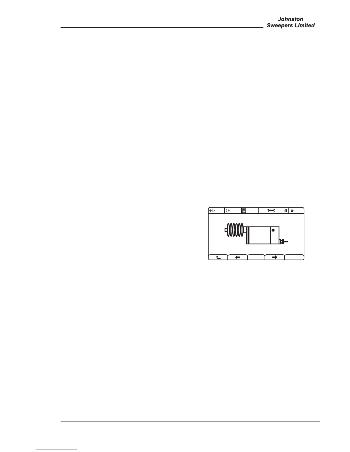
Page Issue 01
Chapter - Remove and Refit Procedures
13:7
VT551 - Maintenance
12. FUEL TANK LH (RED DIESEL) - REMOVAL AND REFITTING
1. Drain fuel tank.
2. Remove the red hand rail.
3. Remove left hand worklamp and access ladder.
4. Remove fuel tank sender and fuel pipes.
5. remove high pressure lance bracket (if fitted).
6. Loosen the 2 tank securing bolts.
7. Slide tank out sideways from support metalwork.
9. refit procedure is the reverse.
13. FUEL TANK RH (WHITE DIESEL) - REMOVAL AND REFITTING
1. Drain fuel tank.
2. Remove right hand worklamp.
3. Loosen the 2 tank securing bolts. Slide tank out part way.
4. Remove fuel sender and fuel pipes.
5. Remove the tank completely.
6. The refit procedure is the reverse.
14. ENGINE ACTUATOR - REMOVAL AND REFITTING
1. Remove actuator.
2. Bolt on new actuator to mounting.
3. Connect electrical plug.
4. Enter CANview menu 4.12.4 and press or to
ensure the actuator is fully extended and stops.
5. Connect up the throttle push rod ensuring that it is
just holding the arm on the injector pump against
the idle speed screw (arm fully clockwise).
Lock off push rod.
93OG. 027-42
50%
14:00
25%4.12.4
All Copyright and rights are the property of Johnston Sweepers Ltd

Page Issue 01Chapter - Remove and Refit Procedures13:8
VT551 - Maintenance
All Copyright and rights are the property of Johnston Sweepers Ltd

Chapter - Fault Diagnosis
CHAPTER
14
Fault Diagnosis
14:1
Table of Contents
Section Page
Power Systems
Hydraulic 14 : 2
Pneumatic 14 : 2
Water 14 : 2
Electrical 14 : 3
Suction System
Suction System 14 : 4
Power Pack
Auxiliary Engine 14 : 5
Sweepgear
Wide Sweep Brush 14 : 6
Channel Brush 14 : 7
Maxigap Nozzle 14 : 7
Discharge
Body Tip 14 : 8
Page Issue 01
VT551 - Maintenance
All Copyright and rights are the property of Johnston Sweepers Ltd

Page Issue 01Chapter - Fault Diagnosis14:2
VT551 - Maintenance
HYDRAULIC SYSTEMS
FAULT SYMPTOM POSSIBLE CAUSE
Hydraulic oil frothing 1. Air getting into system. Check LP pipe to pump,
jubilee clips for tightness.
2. Defective pump shaft seal.
3. Return pipe separated from underside of return
filter inside hydraulic tank.
Sluggish hydraulics 1. Cartridge valve not travelling full extent -
measure oil flow.
2. Blocked filters.
3. Air in oil.
4. Pump output incorrect - measure oil flow.
Fan Speed Too Low 1. Excessive leak off from motor - measure oil flow.
2. Relief valve pressure too low - reset.
PNEUMATIC SYSTEMS
FAULT SYMPTOM POSSIBLE CAUSE
Low pressure warning 1. Air pressure switch faulty.
buzzer on continuously 2. Insufficient pressure in Johnston system.
Constant air leak from 1. Cylinder seals leaking internally.
solenoid block 2. Air solenoid faulty.
WATER SYSTEMS
FAULT SYMPTOM POSSIBLE CAUSE
Jet continuously leaking 1. Grit under armature seating.
2. Armature stuck open.
3. Manual override on.
No water to wash down 1. Water pump filter blocked.
hose or jets 2. Water tank filter blocked.
3. Filter isolation valve closed.
4. Filter assembled incorrectly.
5. Pump valves fitted incorrectly after overhaul.
Lack of pressure 1. Grit under relief valve seating.
2. Relief valve spring broken.
3. Relief valve stuck open.
4. Relief valve worn.
All Copyright and rights are the property of Johnston Sweepers Ltd

Page Issue 01
Chapter - Fault Diagnosis
14:3
VT551 - Maintenance
ELECTRICAL SYSTEM
FAULT SYMPTOM POSSIBLE CAUSE
Beacon not working 1. Check vehicle ignition is on
2. Check beacon bulb/motor
3. Check feed to beacon
4. Check earth wire
5. Check fuse No. 15 or 6 for additional beacons
6. Check switches
7. Check multi plugs to beacon
Work lights not working 1. Check vehicle ignition is on, master switch V is illuminated
2. Check bulb
3. Check feed to light
4. Check earth wire
5. Check fuse No. 13
6. Check switch
Flap (duals) fail to operate 1. Check feed to solenoid/plug LED’s V15 (LH) or V17 (RH)
2. Check solenoid manual override on V15 or V17
3. Check earth wire on pin 13 plug VM
4. Check fuse No. 10
5. Check switch using J-plex screen
Nozzle pneumatic solenoids 1. Check feed to solenoid/plug LED V6 (LH) or V12 (RH)
fail to operate 2. Check solenoid manual override
3. Check earth wire on pin 13 plug VM
4. Check fuse No. 10
5. Check switch using J-plex screen
Channel Brush fails to lower 1. Check feed to solenoid/plug LED V5 (LH) or V11 (RH)
2. Check solenoid
3. Check earth wire on pin 13 plug VM
4. Check fuse No. 10
5. Check switch using J-plex screen
Channel Brush fails to rotate 1. Check feed to solenoids/plug LED Y1 (LH) or Z1 (RH) for
operation
2. Check solenoid
3. Check earth wire
4. Check fuse No. 12
5. Check switch using J-plex screen
Channel Brush water 1. Check feed to solenoid/plug LED’s W3 (LH) or W8 (RH)
fails to operate 2. Check solenoid for operation/obstruction
3. Check earth wire
4. Check fuse No. 8
5. Check water pump for operation
Wide Sweep Brush fails to lower 1. Check feed to solenoids/plug LED’s
2. Check solenoids V23 and V24
3. Check earth wire at pin 13 plug VM
4. Check fuse No. 10
5. Check switch using J-plex screen
Wide Sweep Brush fails to rotate 1. Check feed to solenoid/plug LED valve C1 for operation
2. Check coil for operation
3. Check earth wire
4. Check fuse No. 12
5. Check switch using J-plex screen
Wide Sweep Brush water 1. Check feed to solenoid/plug LED W1
solenoid fails to operate 2. Check solenoid for operation/obstruction
3. Check earth wire
4. Check fuse No. 8
5. Check switch using J-plex screen
All Copyright and rights are the property of Johnston Sweepers Ltd

Page Issue 01Chapter - Fault Diagnosis14:4
VT551 - Maintenance
SUCTION SYSTEM
FAULT SYMPTOM POSSIBLE CAUSE
No pick-up performance 1. Hopper full, causing airflow to be throttled: Discharge load.
2. Nozzle or nozzle trunking blocked or restricted
by debris.
Check the nozzle water jets are not blocked, are
working correctly and lubricating the intake duct.
3. Intake flap not open (dual m/c’s). Blanking plate
not removed after using the wanderhose (single
m/c).
4. Intake void in hopper blocked - clean out.
Poor pick-up performance 1. Maxigap nozzle not set to the optimum opening,
i.e. too close to ground.
2. Nozzle trunking partially restricted by debris.
Check nozzle water jets are working correctly
and so lubricating the duct.
3. Channel brush curtain incorrectly set, not
directing debris in line with nozzle.
4. Intake flap not fully opened (dual m/c’s).
5. Rear body meshes blocked or restricted.
6. Fan case transition ring not correctly set.
7. Fan flap incorrectly set or is incapable of
attaining correct opening due to damaged relay
mechanism.
8. Air silencer pack in roof of cowl blocked
with debris and/or sound absorbent material
separating from its substrate causing a
restriction.
9. Fan case inlet make and break seal fitted to
flanged duct on body front face either degraded
and not sealing or missing. Note: The fan case
outlet seal, unlike the inlet seal, has no effect
on air performance and only provides the
function of a dust seal.
10. Engine is not running at correct operational
speeds. Check fuel filter or air filter blocked/
causing a restriction.
All Copyright and rights are the property of Johnston Sweepers Ltd

Page Issue 01
Chapter - Fault Diagnosis
14:5
VT551 - Maintenance
AUXILIARY ENGINE
FAULT SYMPTOM POSSIBLE CAUSE
Auxiliary engine fails to turn over 1. Check truck ignition is on
2. Check battery and connections
3. Check ignition switch
4. Check starter motor
Auxiliary engine starts 1. Check feed to actuator
but will not accelerate 2. Check fuse
3. Check switch using J-plex screen
Auxiliary engine turns 1. Check fuel tank
over but will not start 2. Check electric feed to engine injector shut off
fuse 2
3. Check injector shut off valve
4. Check fuel lines for loose connections
5. Check oil pressure sender and connections
6. Check water temperature sender
7. Bleed fuel system
All Copyright and rights are the property of Johnston Sweepers Ltd

Page Issue 01Chapter - Fault Diagnosis14:6
VT551 - Maintenance
WIDE SWEEP BRUSH
FAULT SYMPTOM POSSIBLE CAUSE
Not rotating 1. Worn drive adaptor and plate
2. Bearings seized
3. Motor seized
4. Foreign matter jammed in brush
5. Check electrical feed to solenoid/Plug LED valve C
6. Check hydraulic system for pressures for diagnosis of
problem
Rotating slowly 1. Motor worn
2. Hydraulic pump worn
3. Brush end bearing seized
4. Incorrect oil flow and/or pressure
Bouncing 1. Regulator adjustment incorrect
2. Brush stock bent
3. Linkage pins/brackets worn/damaged
4. Air damping system not working
Not dropping 1. Check feed to solenoid/Plug LED V23 and V24
2. Solenoid faulty use man override
3. Switch on control box faulty - check using J-plex
4. Linkage/pivots/cylinders seized
Lifts intermittently 1. Faulty or loose electrical connections while in working
mode - check using J-plex
2. Check solenoid using manual override
Air leaking from Wide Sweep Brush 1. Shuttle valve or regulator defective
2. Lift ram seals worn
Brush not slewing - 1. Check slew cylinder for damage/corrosion
dual sweep machines 2. Solenoid V23 (LH) or V24 (RH)
3. Check slew ram for air leaks
All Copyright and rights are the property of Johnston Sweepers Ltd

Page Issue 01
Chapter - Fault Diagnosis
14:7
VT551 - Maintenance
CHANNEL BRUSH
FAULT SYMPTOM POSSIBLE CAUSE
Brush slows down after 1. Hydraulic pump worn
2. Channel brush motor worn
3. Check hydraulic pressure for fault diagnosis
Works intermittently 1. Check switch in control panel and looms for
loose connections - using J-plex
2. Check hydraulic valves Y1 (LH) or Z1 (RH)
Brush fails to lift 1. Check for electrical power at solenoid/plug LED
V5 (LH) or V10 (RH) if a dual
2. Check pneumatic solenoid for correct operation
3. Seals in cylinder leaking
MAXIGAP NOZZLE
FAULT SYMPTOM POSSIBLE CAUSE
Maxigap will not tilt 1. Check feed to pneumatic solenoid/plug LED V8
(LH) or V7 (RH) if a dual
2. Pneumatic solenoid valve faulty. - check manual
override
3. Cylinder pivot/linkage seized
All Copyright and rights are the property of Johnston Sweepers Ltd

Page Issue 01Chapter - Fault Diagnosis14:8
VT551 - Maintenance
BODY TIP
FAULT SYMPTOM POSSIBLE CAUSE
Rear door will not open 1. Check handbrake is on and earth at plug PC1A pin 2
2. Check master switch V is illuminated
3. Check green safety run button is pressed on pendant unit
4. Check pendant unit has not become unplugged
5. Check feed to solenoids DA (door open) and DB (door close)
Body will not tip 1. Ensure handbrake is on and feed at plug PC1A pin 2
2. Ensure master switch V is on (illuminated)
3. Check feed to solenoids/Plug LED valve BB (raise) and BA (lower)
4. Check green safety run button is pressed on pendant unit
5. Check pendant unit has not become unplugged
All Copyright and rights are the property of Johnston Sweepers Ltd

Chapter - Service Tools
CHAPTER
15
Service Tools
15:1
Table of Contents
Section Page
Service Tools
Service Tools 15 : 2
Page Issue 01
VT551 - Maintenance
All Copyright and rights are the property of Johnston Sweepers Ltd

Page Issue 01Chapter - Service Tools15:2
VT551 - Maintenance
The following tools are available through our Spares Network
TOOL No. ITEM FUNCTION
437-2 Bearing Puller Removal of fan impeller bearings etc
437-3 Pressure Gauge Set Measure hydraulic, pneumatic and
water pressures
437-4 Optical Tachometer Measure fan rpm
437-7 0-55 Litres/Min Flow Gauge Hydraulic flows
437-8 Impulse Adaptor Connects to 437-4 to measure engine
speeds from fuel injection pipes
437-11 Check valve insertion tool To fit check valve 421-278
422-1 Body Eye Bolt Raising/lifting of body
KT 01893 Workshop Prop VT551 tip ram - see Chapter 13
283643-1 Scraper Cleaning fan impeller
All Copyright and rights are the property of Johnston Sweepers Ltd

Chapter - Warranty
CHAPTER
16
Warranty
16:1
Table of Contents
Section Page
Warranty
Warranty 16 : 2
Page Issue 01
VT551 - Maintenance
All Copyright and rights are the property of Johnston Sweepers Ltd

Page Issue 01Chapter - Warranty16:2
VT551 - Maintenance
1 WARRANTY TERMS AND CONDITIONS
Johnston Sweepers Limited (JSL) undertakes to repair or replace, free of charge, any part manufactured
by it which is proved to be defective through inadequate workmanship or materials during the first two
thousand hours of operation, or within a period of twelve months (whichever is the sooner) from the date
of delivery from JSL unless the warranty is registered to the buyer (the Customer) through our website
at http://www.johnstonsweepers.com/warranty_registration.asp. This warranty is not transferable. Any
original equipment part replaced at JSL cost carries the remaining period of warranty for any defective
material or workmanship. Qualifying parts fitted outside the JSL machine warranty period carry a twelve
months parts only warranty for defective material or workmanship.
Warranty is given subject to the following conditions:
a) The machine shelf life of 6 months has not been exceeded. “Shelf Life” means time stored in good
condition by the distributor from the date on which the product was despatched by JSL.
For
spare parts the shelf life is 1 year.
b) A suitable working area is provided for the work required.
c) Adequate written notice of the defect is submitted to JSL within 30 days of the discovery of the
defect. This must include a written detailed report describing the problem, the circumstances
applying at the time and any additional relevant information. The report must contain sufficient
information to allow JSL to understand the problem and action taken. Claims relating to damage
incurred during delivery to the Customer must be notified within 24 hours of receipt of the
equipment.
d) Defective parts are held by the Customer until disposal has been authorised by JSL. If JSL
requests the return of the parts then JSL will pay reasonable carriage charges.
e) The defect has not been caused by carelessness, vandalism, accident, incorrect maintenance,
improper operation, abnormal working conditions, tampering with sealed settings, failure to follow
JSL’s instructions, inadequate lubrication or fair wear and tear.
f) For parts not manufactured by JSL, no attempt shall have been made to dismantle or repair the
parts without the written approval of the relevant manufacturer, JSL, or an authorised agent of
either.
Replacement parts for warranty claims shall be purchased and a claim submitted to recover costs. Parts
replaced under warranty will be credited along with carriage charges for that item. JSL will not pay any
Customer profit element on parts replaced under warranty.
JSL will not be liable for replacement of any parts designated as consumable items (see separate list,
available on request), for fuel, hydraulic fluid, antifreeze or lubricants used in maintenance or warranty
work, downtime or for any consequential loss or charges, including transportation or recovery charges.
As JSL are not authorised repairers of engines or proprietary chassis’ JSL are unable to accept any
claims relating to them. JSL will therefore pass on to the customer the benefit of any warranty provided
by the manufacturers in respect of them and as such any repairs or claims should be submitted to the
manufacturer or its locally appointed agent. Any claim received by JSL for such repairs will be forwarded
to the relevant manufacturer for their acceptance before it is credited.
This warranty applies only to the original equipment supplied by JSL and genuine Johnston spare parts.
It shall not apply to unauthorised alternative parts or materials or any consequential damage or failure
resulting from the use of fitting of such parts or materials.
Provided that the claim is justified and that the correct procedure has been followed, claims will be paid
within 30 days of receipt. Offset of claims against sums due to Johnston is hereby specifically prohibited.
All Copyright and rights are the property of Johnston Sweepers Ltd

Page Issue 01
Chapter - Warranty
16:3
VT551 - Maintenance
ENGINES
The standard warranty from the engine’s supplier is passed on in full without reduction as specified in
the engine manufacturers standard Terms and Conditions.
FUELS
In line with the engine manufacturers specifications all fuel used must be in line with EN590:1993 and can
incorporate a maximum of 5% Bio-diesel.
2 CONSUMABLES LIST
Body Inlet Ducts, Flaps and Meshes
Brush Linkages, Bushes and Pivots
All Sweeping Brushes
Drive Couplings, Bearings and Belts
Curtains and Mudflaps
Filters and Elements
Impellers and Casings
Supawash Hoses, Jets, Lances and Fittings
Lift Cables
Light Bulbs and Fuses
Nozzles, Nozzle Wheels and/or Skids, Guards, Rubbers and Retaining Strips,
Nozzle and Wanderhose Trunkings
Seals and Rubbers
Tyres and Friction Materials
Wanderhose Turrets, Ducts, and Bearings
Water Jets
Water Pump Pistons, Diaphragms, Seals and Rotors
Wearing Plates, Strips and Baffles
Windows, Mirrors and Inspection Glasses
Any other items normally regarded as consumables
3 EXTENDED WARRANTY OPTIONS
JSL offer 2 extended warranty options, Silver or Gold to cover the whole machine (excluding proprietry
chassis) for upto 3 years, or 6000 hours, whichever the sooner..
• The Silver Warranty provides full cover for year 2, upto 4000 Hours
• The Gold Warranty provides full cover for years 2 and 3, upto 6000 Hours
All other terms and conditions are as described above.
All Copyright and rights are the property of Johnston Sweepers Ltd

Page Issue 01Chapter - Warranty16:4
VT551 - Maintenance
YOUR COMMITMENT
In order to register your warranty please complete and return the form below.
I have read the Warranty Terms and Conditions as shown above and understand that the equipment must
be operated and maintained in accordance with requirements of this warranty to retain entitlement to its
benefit. Any failure to comply with conditions shown above renders this warranty null and void and the
standard 12 month warranty then applies.
(tick as appropriate)
This form registers the Standard Silver Gold warranty for the following vehicle.
To register the date into service, please complete and return.
Model Delivery Date
EQ No Registration No
Signed by or on behalf
of the Purchaser
Name
Position
Date
The vehicle is located at
The vehicle is serviced / maintained at the following depot
Depot Manager details
Name
Telephone
Fax
Please forward the completed form to the Warranty Department at the following address:
JOHNSTON SWEEPERS LIMITED
CURTIS ROAD
DORKING
SURREY
RH4 1XF
TEL: +44 (0)1306 884722
FAX: +44 (0)1306 740369
e-mail: warranty@johnstonsweepers.com
Rev. 11 doc
01.11.07.
All Copyright and rights are the property of Johnston Sweepers Ltd
 Loading...