

Page 1
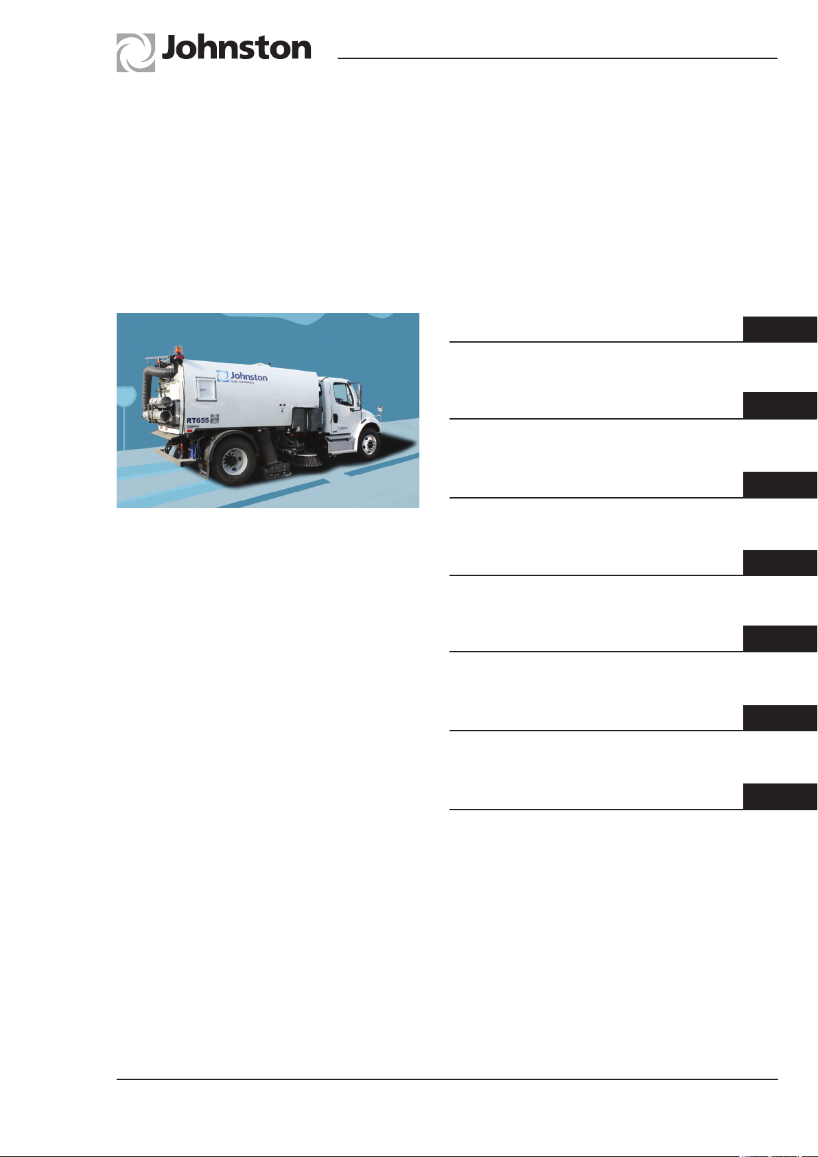
Operator’s
Guide
Johnston Sweepers Limited
RT655 Mk III
Regenerative Air
Twin Engine
Suction Sweeper
From Manufacture Sequence No. 7458
General Arrangement
Controls
Operation
Optional Equipment
Chapter not used
Routine Maintenance
1
2
3
4
5
6
Part No 01288-1(GB)
Revision Level A
E.C.N. 712675 Print date - 16/11/2015
Conformity Certificates
7
Page 2

RT655 Operator’s Guide
Foreword
The Johnston RT655 Air Regen Sweeper represents the highest grade of craftsmanship and
reliability that makes Johnston probably the world leader in sweeping technology.
This machine is designed for the removal of spoil on traffic or pedestrian areas, and litter collection
using the Wanderhose [EN 13019 refers], and should only be driven by trained operatives.
This machine should not be used for sweeping hot or burning substances. In the unlikely event of
a fire, normal powder or foam fire fighting equipment can be used on this product.
An operator should receive training in the follow elements:
1 Safety Observations/Notices
2 Transit driving
3 Correct use of body prop
4 In cab controls
5 External controls
6 Sweeping techniques
7 Load discharge
8 Channel brush (gutter broom) setting changing
9 Nozzle (pick-up head) setting
10 Daily and weekly maintenance items
11 Driving/operation assessment
12 End of day cleaning of body and machine
Johnston Sweepers Limited can provide operator training upon request.
We would point out that it is the employers responsibility to carry out his own Risk Assessment on
the equipment in his particular working environment and work application.
This handbook should be carefully studied. In it you will find instructions for the operation and
maintenance of your JOHNSTON SWEEPER.
It is vitally important that the operator and maintenance staff have a copy of this book. The life of
the machine will depend upon following these instructions in respect of regular maintenance and
correct operating methods.
It is important that only GENUINE JOHNSTON SPARE PARTS are used when servicing and
maintaining the sweeper. This is especially important for consumables, filters etc, as the use of
non-genuine parts may cause premature failure and invalidation of warranty.
When carrying out maintenance or part replacement, additional explanatory illustrations can be
found in the Parts Manual, which shows and lists hardware, and availability of spares with the
orientation and positions of the various components.
Foreword
Page Issue A
Page 3

RT655 Operator’s Guide
Johnston Sweepers Limited
Safety Notice
The universal safety symbol is used throughout this manual to indicate information which
is essential for health and safety for all operating personnel.
Ear defenders are recommended when working around the machine
Eye protection is recommended when working around the machine
Johnston® JOHNSTON ® JOBRO ® BROOMVAK
®
are registered trade marks of Johnston Sweepers Limited.
All copyrights and rights reserved. The reproduction, distribution and utilisation of this document
as well as the communication of its contents to others without express authorisation is prohibited.
Offenders will be held liable for the payment of damages. All rights reserved in the event of the grant
of a patent, utility model or design.
Every endeavour has been made to ensure that the information contained in this Operator’s Guide
is correct, but due to continuous product development, the Company reserve the right to alter its
contents without notice. This document should not be interpreted as being part of a formal contract.
For further information and enquiries please contact:
Johnston Sweepers Limited
Curtis Road, Dorking, Surrey RH4 1XF, UK
Tel: +44 (0)1306 884722
Fax: +44 (0)1306 884151
E-mail: [email protected]
Web: www.johnstonsweepers.com
Page Issue A
Foreword
Page 4

RT655 Operator’s Guide
Page Issue Levels
Page Issue Changed Page Issue Changed
Front Page A Foreword 1 A
Foreword 2 A Foreword 3 A
Foreword 4 A Foreword 5 A
OG1:1 A OG1:2 A
OG1:3 A OG1:4 A
OG2:1 A OG2:2 A
OG2:3 A OG2:4 A
OG2:5 A OG2:6 A
OG2:7 A OG2:8 A
OG3:1 A OG3:2 A
OG3:3 A OG3:4 A
OG3:5 A OG3:6 A
OG3:7 A OG3:8 A
OG3:9 A OG3:10 A
OG3:11 A OG3:12 A
OG4:1 A OG4:2 A
OG4:3 A OG4:4 A
OG4:5 A OG4:6 A
OG6:1 A OG6:2 A
OG6:3 A OG6:4 A
OG6:5 A OG6:6 A
OG6:7 A OG6:8 A
OG6:9 A OG6:10 A
OG6:11 A OG6:12 A
OG6:13 A OG6:14 A
OG6:15 A OG6:16 A
OG6:17 A OG6:18 A
OG7:1 A OG7:2 A
OG7:3 A OG7:4 A
Foreword
Page Issue A
Page 5
RT655 Operator’s Guide
INTERNATIONAL SYMBOLS
Conforming to ISO 3767
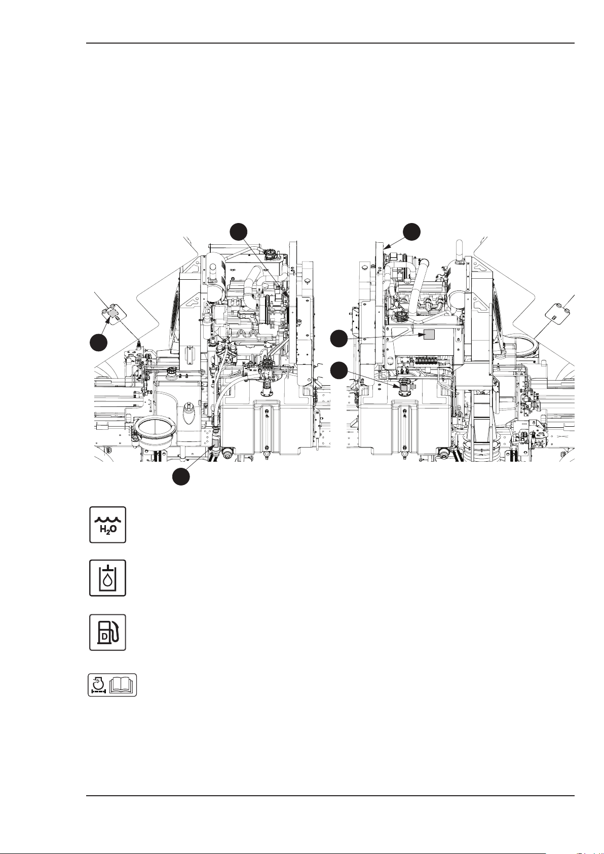
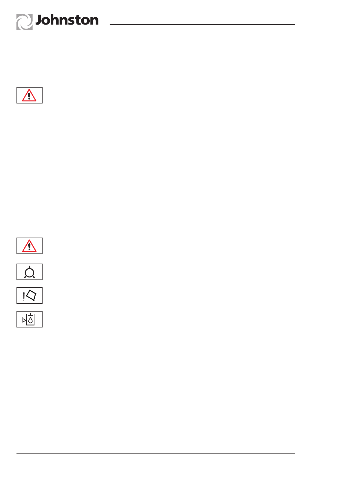
Graphical symbols are used to indicate the water, fuel and hydraulic oil tank filler ports and air
cleaner servicing instructions.
Their location and descriptions are shown below.
Johnston Sweepers Limited
4
3
2
4
1a
1b
RTOG.049
1. Water tank filler ports 1a = Hose Pipe
1b = Hydrant
Page Issue A
2. Hydraulic oil tank filler
3. Fuel tank (diesel) filler
4. Engine air cleaner instructions, i.e. use only genuine Johnston replacement
air cleaner elements and refer to Chapter 6 of this guide for servicing
instructions
Foreword
Page 6
RT655 Operator’s Guide
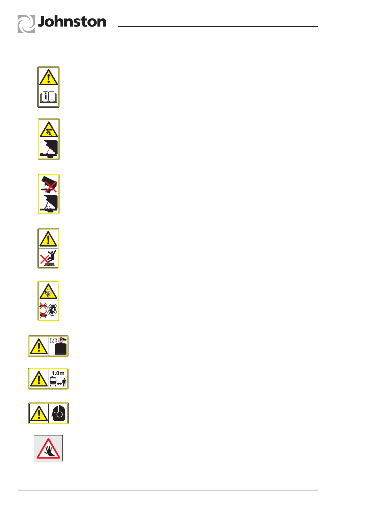
Safety Symbol Descriptions
Safety alert symbol
Read Operator’s Guide
Ensure body prop is engaged in rack before working under raised body
Body prop NOT engaged in rack
Body prop correctly engaged in rack
Keep clear of brushes
Do not open suction fan safety flap while fan is running
Never reach in or drop tools into the fan case
Release radiator cap carefully when hot to avoid scalding
Stay at least 1 metre distance from the machine
Foreword
Wear ear defenders when working in this area
Sharp objects warning - there can be a risk of injury from sharp objects such
as discarded hypodermic needles becoming lodged in the sweeping system.
The use of ‘needle stick gloves’ is recommended when changing brushes,
using the wanderhose/Littasnatch and when cleaning out the machine
Page Issue A
Page 7

RT655 Operator’s Guide
Johnston Sweepers Limited
CHAPTER
1
General Arrangements
Table of Contents
Subject Page
General Arrangement
General Arrangement Drawing OG1 : 2
Page Issue A
Chapter - General Arrangement
OG1:1
Page 8
RT655 Operator’s Guide
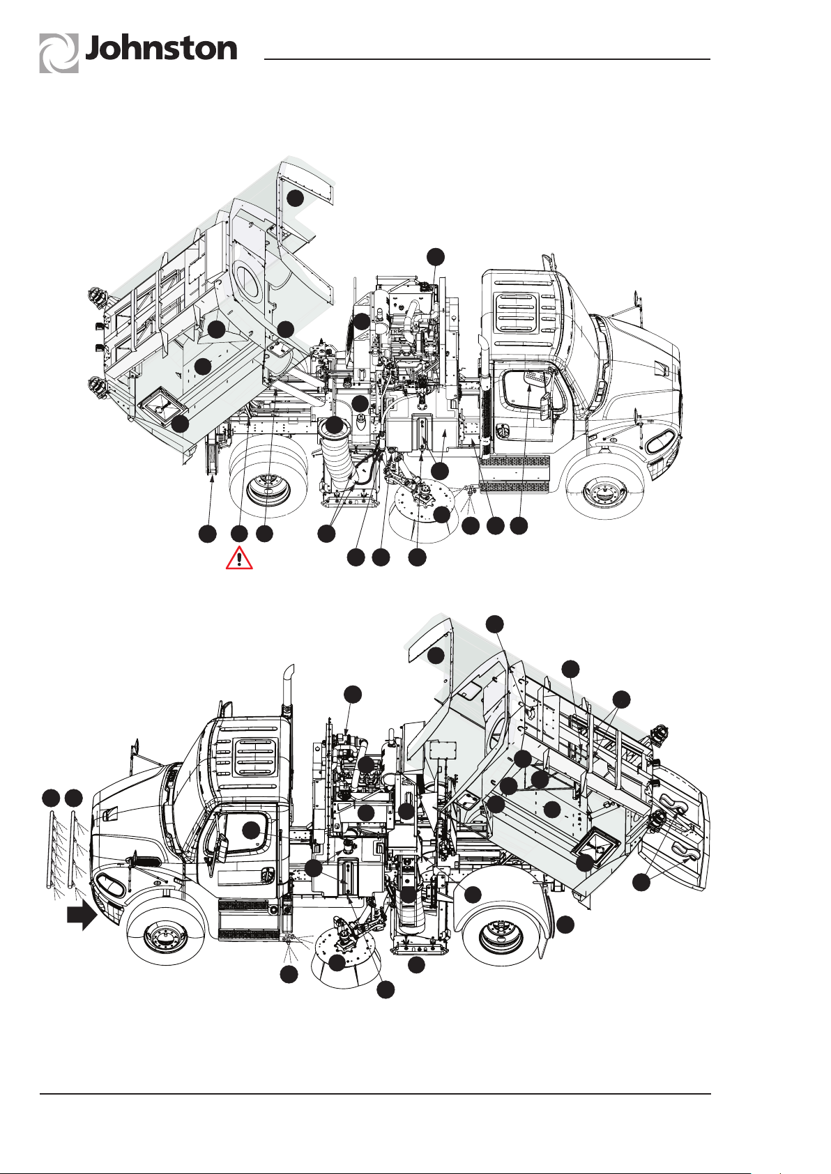
GENERAL ARRANGEMENT
Figure 1
2
34
14
1
29
3 22
37
Cold Weather Drains
30
12
8
5
25 27
34
26
23
13
2
30
36
21
33
16
17
6
31
30
OG1:2
4
7
35
24
13
30
RH Sweep machine shown
Chapter - General Arrangement
26
11
18
15
19
8
10
20
9
1
29
28
32
RTOG.051
Page Issue A
Page 9

RT655 Operator’s Guide
Item Component See Chapter
Johnston Sweepers Limited
1 Hopper/load compartment -
2 Auxiliary engine cowl -
3 Body (hopper and cowl) prop 3
4 Auxiliary engine 6
5 Fuel tank -
6 Fuel tank filler access flap -
7 Hydraulic oil reservoir 6
8 Suction fan case 6
9 Variable exhaust gate (VEG) -
10 Pick-up head (hood) 6
11 Blaster duct -
12 Suction duct -
13 Channel brush / gutter broom 6
14 Wear plate -
15 Filter screen 6
16 Filter screen curtain 6
17 Filter screen water sprays 6
18 ‘SepaVac’ separator box 3
19 ‘SepaVac’ access panel -
20 ‘SepaVac’ discharge door 3
21 ‘SepaVac’ water flush 3
22 ‘SepaVac’ water flush hydrant connection 3
23 * R.H. Water tank and contents gauge 6
24 * L.H. Water tank, contents gauge and hose filler 6
25 Water tank(s) hydrant filler 6
26 Water tank drain tap - under both tanks 6
27 Water pump suction filter 6
28 Rear door drainage hoses 3
29 Rear door access door 3
30 Low pressure water spray jets -
31 High pressure Water spray jets -
32 Washdown hose -
33 Master control panel 2
34 Air cleaner 6
35 Air cleaner filter state indicator 6
36 Hydrant hose stowage - optional -
37 Supawash hose reel & handlance 4
* Total water capacity 950 litres
Page Issue A
Chapter - General Arrangement
OG1:3
Page 10

RT655 Operator’s Guide
OG1:4
Chapter - General Arrangement
Page Issue A
Page 11

RT655 Operator’s Guide
Johnston Sweepers Limited
CHAPTER
2
Controls
Table of Contents
Subject Page
Operating Controls - In Cab
Switch Panel OG2 : 2
Cab Mounted Controls OG2 : 6
Operating Controls - External
Load Discharge Control Pendant OG2 : 7
Fuse Functions
Fuse Functions OG2 : 8
Page Issue A
Chapter - Controls
OG2:1
Page 12
RT655 Operator’s Guide
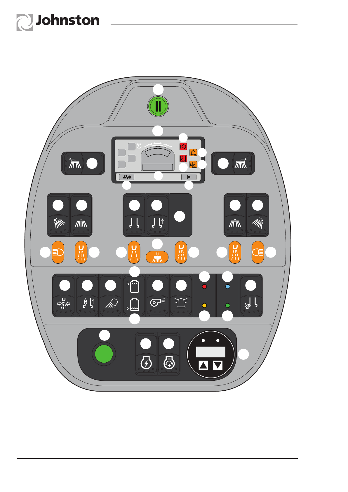
Sweeping Controls - Switch Panel
A
B
B1
2200
1200
B2
C1 C2
B6
15hrs
B5
B3
B4
B7
D1 E1 F G E2 D2
H
L
J1 K1
K1 J2K2 K3
P1
T1
T2
M O
N
P2
Q
S1
R
S2
U
OG2:2
V
Chapter - Controls
W
X
Src:Eng
SPN00000
*Denotes Optional Equipment
Y
RTOG.042
Page Issue A
Page 13
RT655 Operator’s Guide
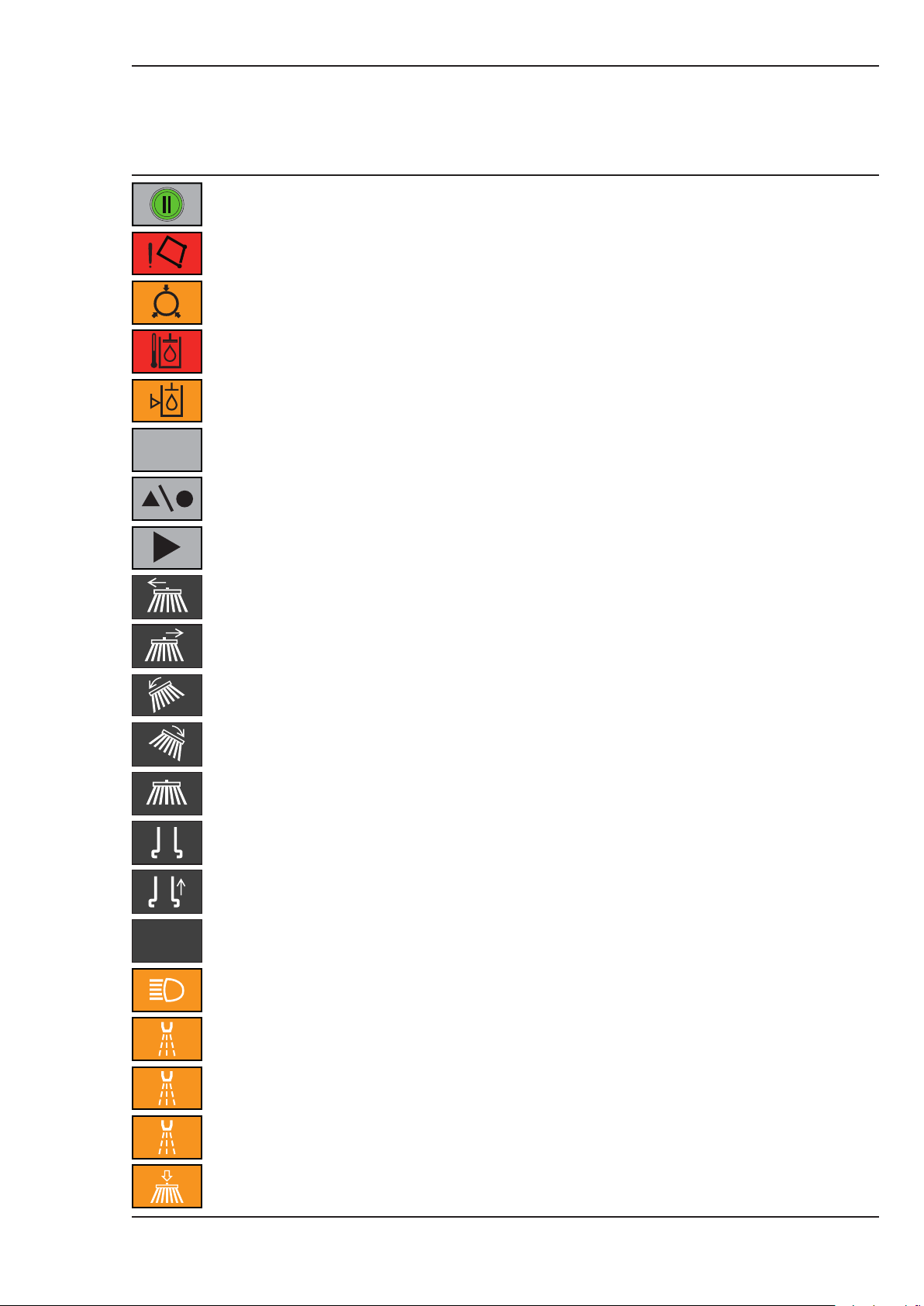
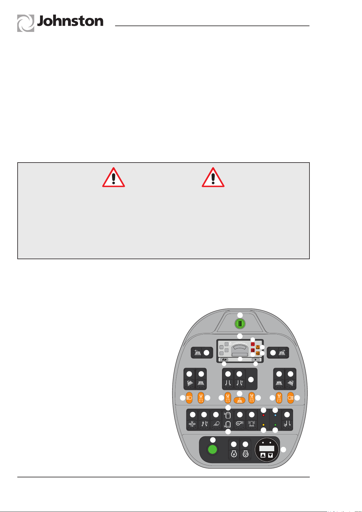
Symbol ID Description
A Programme Button; ON/OFF switch illuminates when pressed and suspends
all sweeping and parks brushes. Pressing again reactivates previous settings.
B1 ‘Hopper Raise’ - red warning lamp and buzzer.
B2 ‘Low Air Pressure’ - amber warning lamp and buzzer.
B3 Hydraulic Oil ‘Temperature’ - red warning lamp.
B4 Hydraulic Oil ‘Low Level’ - amber warning lamp and buzzer.
Johnston Sweepers Limited
Sweeping Controls
15hrs
B5 Rear Broom hours worked/clock.
B6 Push button to select hourmeter reading/clock - cancels after 10 seconds.
B7 Advance button - advances clock time when in clock setting mode.
C1 *LH Variabrush - spring centred switch moves brush out or in.
C2 *RH Variabrush - spring centred switch moves brush out or in.
D1 * LH Rotatilt - spring centred switch; alters angle of Gutter broom to suit road
camber.
D2 * RH Rotatilt - spring centred switch; alters angle of Gutter broom to suit road
camber.
E1/E2 LH/RH Gutter Broom 2 position switch - stowed/active illuminated when
selected.
F Pick-up head and water sprays; 3 position switch - stowed/active/water
sprays. Illuminated when selected.
G Pick-up head hop; 2 position - push to make stowed / CLOSED / OPEN.
Page Issue A
H Blank.
J1/J2 LH/RH worklamp; 2 position switch OFF/ON. Illuminated when selected.
K1 Front Spray Bar. 2 position switch OFF/ON illuminated when selected.
K3 Gutter Spray. 2 position switch OFF/ON illuminated when selected.
K3 Hopper Spray. 2 position switch OFF/ON illuminated when selected.
L * Powathrust; - ON/OFF. Increases Channel Brush ground pressure to
preset level when on. Without the need to re-adjust the in cab regulator.
Chapter - Controls
OG2:3
Page 14
RT655 Operator’s Guide
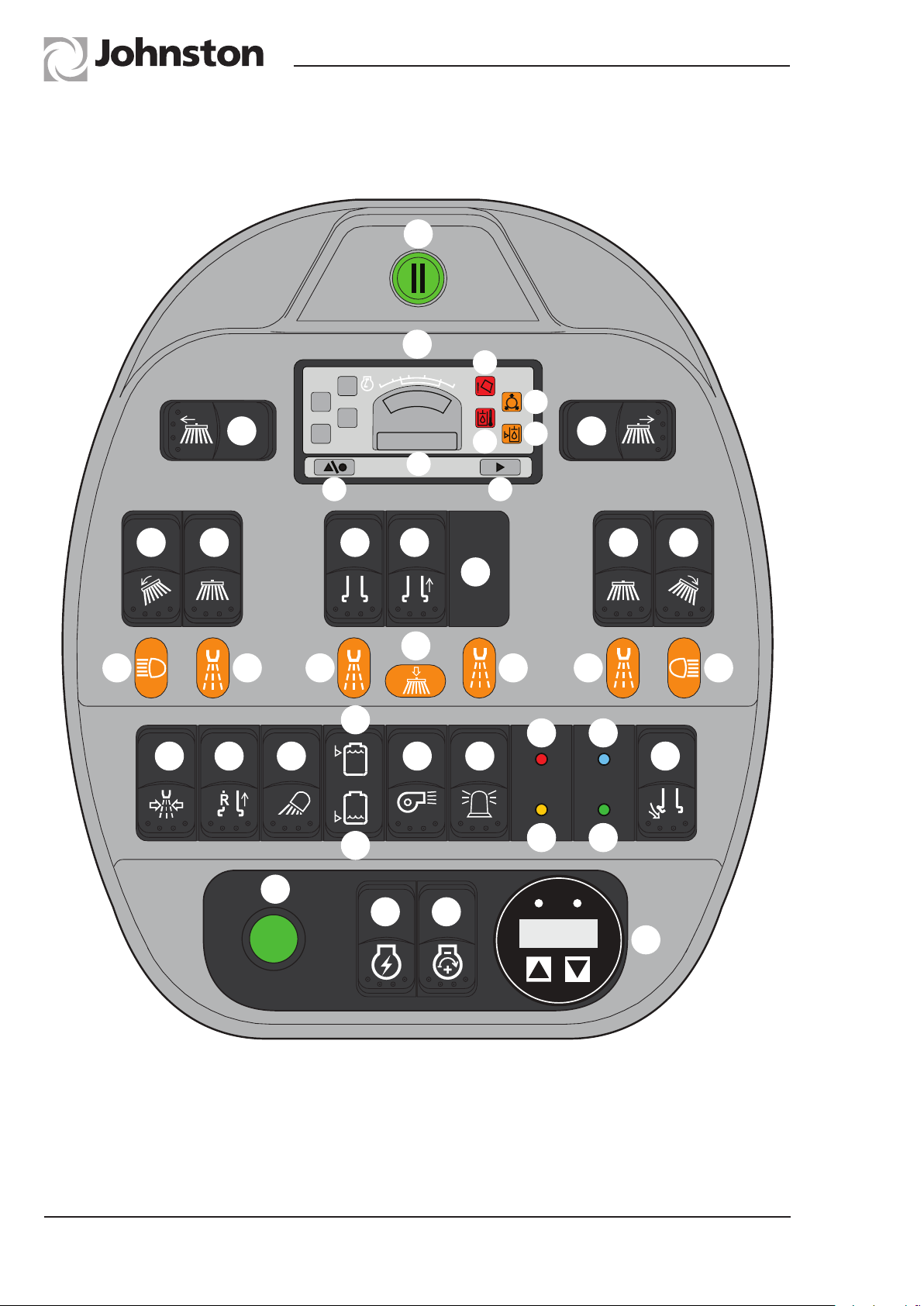
Sweeping Controls - Switch Panel
A
B
B1
2200
1200
B2
C1 C2
B6
15hrs
B5
B3
B4
B7
D1 E1 F G E2 D2
H
L
J1 K1
K1 J2K2 K3
P1
T1
T2
M O
N
P2
Q
S1
R
S2
U
OG2:4
V
Chapter - Controls
W
X
Src:Eng
SPN00000
Y
RTOG.042
Page Issue A
Page 15
RT655 Operator’s Guide
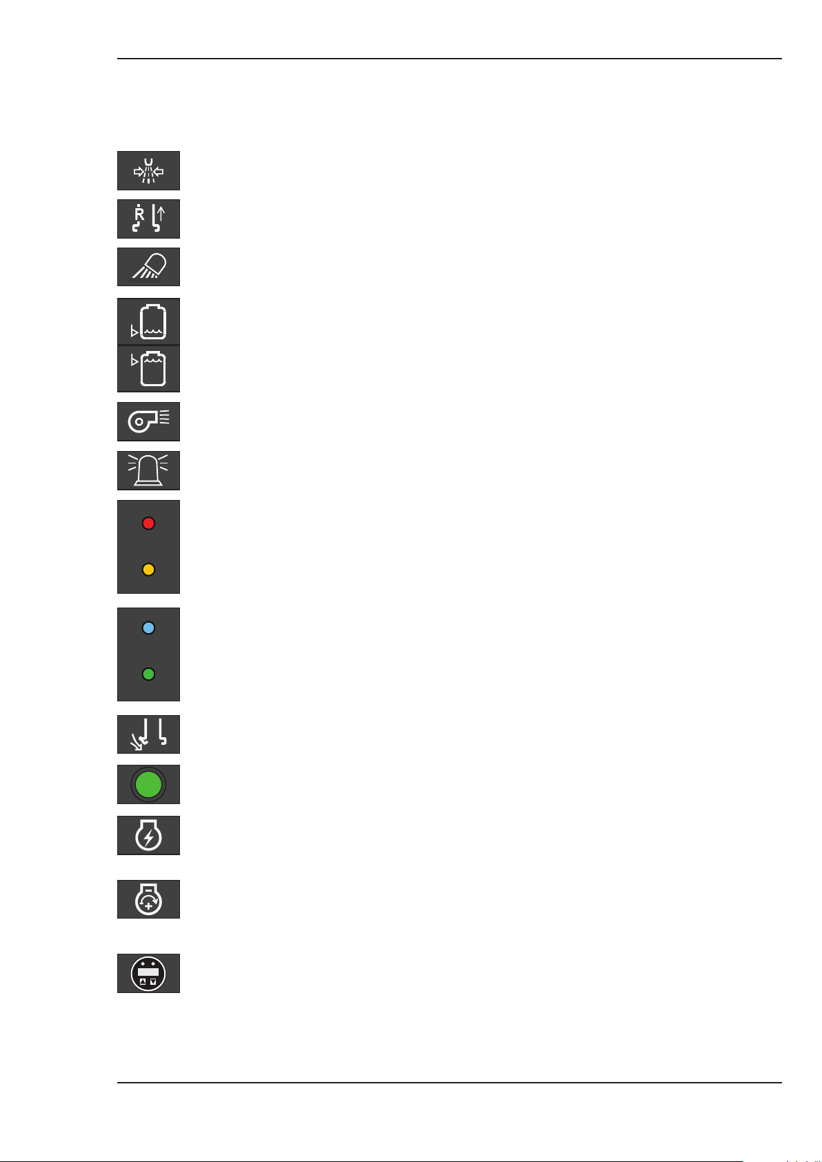
Symbol ID Description
M Supawash option; 2 position switch - OFF/ON illuminated when selected.
N Hood reverse pick-up select switch; 2 position switch - OFF/ON.
O Rear Worklamp; 2 position switch OFF/ON illuminated when selected.
P1 Water tank low level indicator - illuminated when tank empty.
P2 Water tank high level indicator - illuminated when tank is full.
Q Powasave – 2 position switch – operates with gutterbroom. Overrides pre-
set pressure level to allow maximum down pressure on brush.
Johnston Sweepers Limited
Sweeping Controls
R Beacons; 2 position switch - OFF / ON. illuminated when selected.
S1 VEG - position 1. Regen Mode - Colour Red
S2 VEG - position 2. 60% Regen - Colour Yellow
T1 VEG - position 3. 30% Regen - Colour Blue
T2 VEG - position 4. Vacuum Mode - Colour Green
U VEG opening switch; 3 position sprung centred switch controls an electrical
actuator CLOSED / OFF / OPEN.
V Engine crank button - push to crank. Flashes to indicate engine fault
requests.
W Ignition switch - 2 position - OFF/ON.
NB : Only beacons will operate when switch is off.
Src:Eng
SPN00000
Page Issue A
X Engine throttle control; 3 position spring centred switch
REDUCE/OFF/ INCREASE.
Y CAN FED - John Deere, Diagnostics, Engine hours, Engine RPM, Coolant
Temperature, John Deere Fault codes.
*Denotes Optional Equipment
Chapter - Controls
OG2:5
Page 16
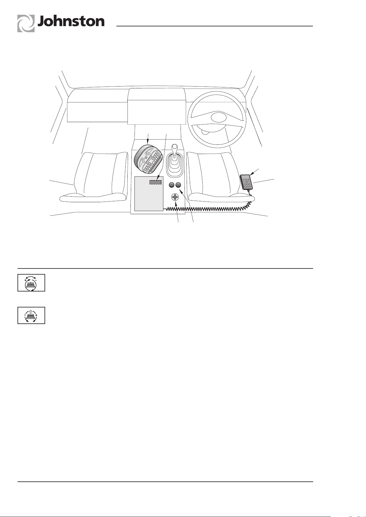
Cab Mounted Controls
CC
FF
RT655 Operator’s Guide
DD
Symbol Switch Description
AA Channel brush speed control; clockwise rotation increases brush
speed.
BB Pressure control for each gutter broom Powasave; clockwise rotation
reduces brush pressure.
CC Fuse box is mounted inside relay box. Fuse functions - see page OG2:8.
DD Load discharge pendant unit mounted by driver’s seat.
FF Switch panel - see previous pages of this chapter.
AA
BB
RTOG. 010-2
OG2:6
Chapter - Controls
Page Issue A
Page 17
RT655 Operator’s Guide
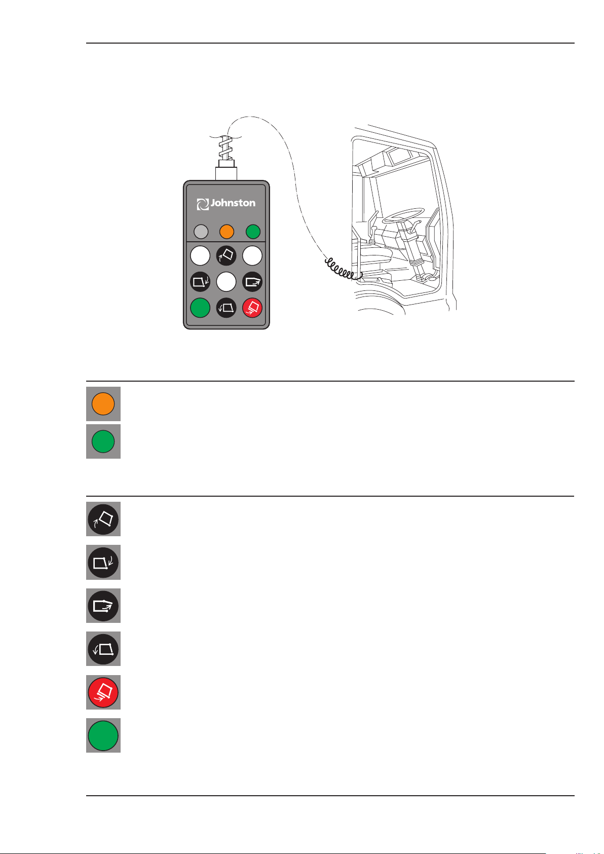
Load Discharge Control Pendant
(Located beside the driver’s seat)
Johnston Sweepers Limited
LED Function
Hand brake off - Pendant not ready for operation
Hand brake on - Pendant ready for operation
Switch Function
Raises body
Closes rear door
Opens rear door
M02OG-005
Page Issue A
Lowers body
Stows body prop when body is raised and not resting on it
Green safety switch must be pressed to enable discharge functions
Chapter - Controls
OG2:7
Page 18
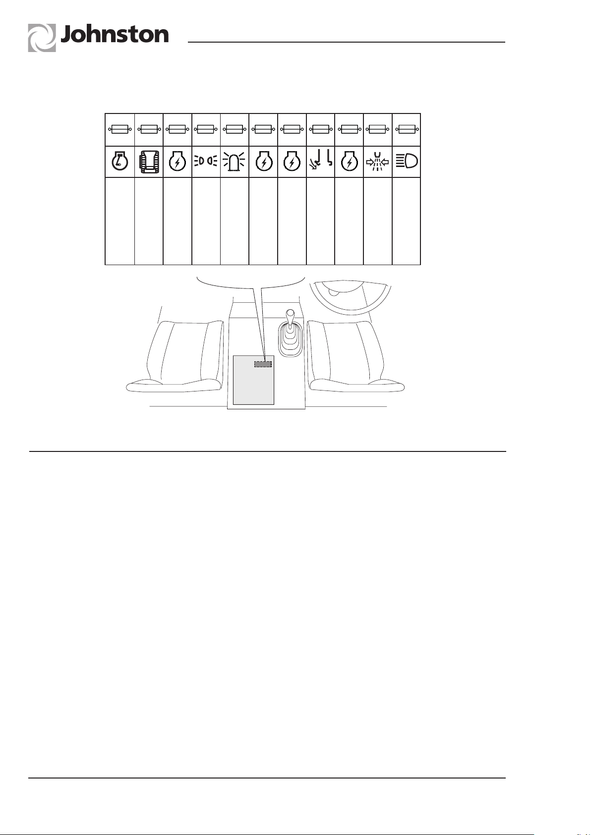
Fuse Functions
RT655 Operator’s Guide
F11
20A
AUX ENGINE
20AF320A
CRANK
POWER I/O NODE
F10
F2
10A
20A
ECU POWER
AUX ENGINE
MARKER LIGHTS
F1
BEACONS
F8
15A
IGNITION
CHASSIS
F9
10A
VEG SENSORS
CHASSIS IGNITION/
SUPAWASH CONTROLS/
F6
15A
20A
GATE
POWER VEG
F7
F4
20A
IGNITION
AUX ENGINE
WATER/SUPAWASH/
F5
15A
ROTATILT
WORK LIGHTS/
WATER SWITCHES
RTOG.011-2
Fuse No. Function Amps
F1 Beacons 20
F2 Marker Lights 10
F3 Power I/O Node 20
F4 Water/Supawash/Rotatilt 20
F5 Work Lights/Water Switches 15
F6 Power VEG Gate 20
F7 Aux Engine Ignition 15
F8 Chassis Ignition 15
F9 Chassis Ignition/Supawash Controls/VEG Sensors 10
F10 Aux Engine ECU Power 20
F11 Aux Engine Crank 20
Fuse colour key
5 Orange 10 Red 15 Blue 20 Yellow
OG2:8
Chapter - Controls
Page Issue A
Page 19

RT655 Operator’s Guide
Johnston Sweepers Limited
CHAPTER
3
Operation
Table of Contents
Subject Page
Towing and Craning
Towing the Vehicle OG3 : 2
Craning the Vehicle OG3 : 2
Engine
Engine Starting and Operation Procedures - John Deere OG3 : 3
Sweeping
Commence Sweeping OG3 : 5
Hood Hop OG3 : 6
Interrupt Sweeping OG3 : 6
Terminate Sweeping OG3 : 6
Water Drainage OG3 : 6
Blocked Pick-up Head /Suction Duct OG3 : 7
Load Discharge and Auto Body Prop OG3 : 8
Emergency Discharge Pump OG3 : 10
Sweeping in Cold Temperatures OG3 : 11
Cold Weather Precautions OG3 : 12
Page Issue A
Chapter - Operation
OG3:1
Page 20

RT655 Operator’s Guide
Craning the Vehicle
The vehicle may be lifted using conventional lifting systems that are slung from the vehicle road
wheels. However, it is necessary to ascertain the centre of gravity as it can be up to 20% from the
mid point of the wheelbase. The exact position is dependent upon chassis type and vehicle build.
Towing the Vehicle
Refer to the chassis handbook.
Safety Notice
Please note the air system needs to be charged to ensure the channel brush / gutter
broom is raised.
OG3:2
Chapter - Operation
Page 21
RT655 Operator’s Guide
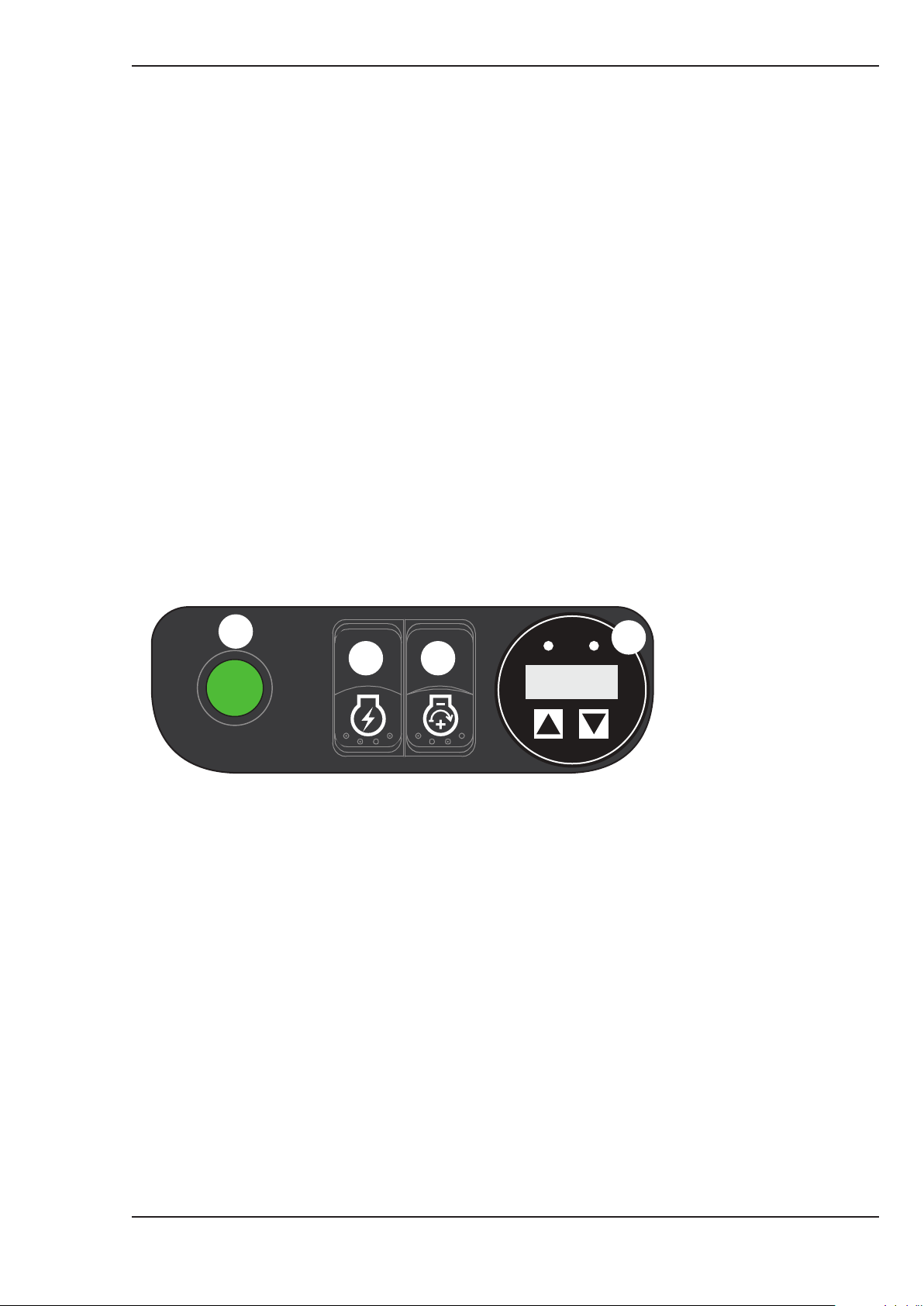
ENGINE STARTING AND OPERATION PROCEDURES - JOHN DEERE
Before driving the sweeper, it is advisable to have the chassis engine running as it is necessary to
ensure there is adequate air pressure to raise the sweepgear from the ground.
Ensure sweepgear switches are turned off.
NB : The chassis ignition switch must be turned on to energise the switch panel. Never engage
engine cranking for longer than 60 seconds as this can damage the starter motor.
John Deere Electronic Engine
Starting Hot or Cold
Press the ignition switch (W) to its on position, it will illuminate.
(V) will illuminate to show engine preheating is active. When light goes out press crank button (X)
release when engine fires.
Johnston Sweepers Limited
(X) is the throttle and will increase engine RPM to 1500 before needing ECO mode override button
(Q) to 2000 RPM.
V
W
X
Src:Eng
SPN00000
Y
RTOG.047
Page Issue A
Chapter - Operation
OG3:3
Page 22
RT655 Operator’s Guide
ENGINE STARTING AND OPERATION PROCEDURES.
Engine Operation Warning System
The engine will automatically be shut down in the event of loss of lubrication oil
pressure or coolant overheat. Illumination of the relative warning lamps occurs if these
conditions prevail. Testing the oil lamp occurs automatically when the ignition switch
is initially turned ON. The water temperature warning light will only illuminate when
cooling water reaches 110°C.
Engine Speed Regulation
The throttle speed switch is a spring centred switch operating an electric variable speed engine
control. The engine speed is between 1200 and 2000 rev/min to suit sweeping conditions. The Eco
Override button (Q), need pushing to increase engine RPM higher than 1500.
NB: If the truck and auxiliary engine use a single fuel tank. When the fuel gauges reaches ¼ full,
stop the auxiliary engine as there is a chance it could run out of fuel, meaning the fuel system would
need to be bled again.
System Warning Alarms
Audible warning system. A warning buzzer will sound with the appropriate warning
light if the following exists.
Low air pressure.
Body not completely lowered.
Low hydraulic oil level - could indicate a leak on the hydraulic system.
Setting Clock
The clock (12 hour) can be set with the ignition OFF - clock time should be displayed. Press B11
and hold. Clock time will flash. Release B11 and hour mode will flash. Adjust hours by pressing
B12.
Press B11 again and minutes will flash; set by pressing B12.
When time is correct, press B11 to revert to clock display.
NB: Clock setting display cancels after 30 seconds.
OG3:4
Chapter - Operation
Page Issue A
Page 23

RT655 Operator’s Guide
To Commence Sweeping
1. Start vehicle engine.
2. Ensure the intake blanking plate is not blanking the tube and is stowed on the body underside.
3. Start auxiliary engine.
4. Ensure warning beacons are operating - switch (R).
5. Ensure programme button (L3) is not illuminated.
6. Increase engine speed up to 1500 rev./min.
7. Lower pick-up head (G2) and lower channel brushes (gutter brooms) as required (E1/E2). NB:
The brushes move out to their full working position whilst turning. Third position activates Hood
Water Sprays.
8. Set additional water jets to suit the debris being swept (J2, K2). Always operate (K3) body
interior sprays.
9. Commence sweeping at a forward speed between 2-12 kph depending upon the debris being
swept. Always use the slowest channel brush between 10 and 100 rpm to give satisfactory
suction performance.
10. The position of the channel brush can be altered (moved towards the chassis) by operating
switches C1 and C2 for the LH and RH channel brushes.
11. The channel brush ground pressure can be reduced by operating the Powasave regulations
BB.
Johnston Sweepers Limited
It is necessary to select the correct position of the VEG gate for the type of material being swept.
A simple guide is as follows:-
Material Decals illuminated Colour VEG Position
Heavy sweep S1 Red 1 - Regen
General litter S2 Yellow 2 - 60% Regen
General sweep T1 Blue 3 - 30% Regen
Light sweep (leaves) T2 Green 4 - Vacuum Mode
Page Issue A
Chapter - Operation
OG3:5
Page 24
RT655 Operator’s Guide
Hood Hop
The Hood Hop feature is a versatile way to overcome bulky debris when sweeping. The pick-up
head hop switch is instant. It reacts to lift the hood for as long as the button is pressed.
When bulky items or a mass of leafs are in front of the hood. A quick press of the button, allows the
hood just to lift to bring in the excess material and sweep it away.
The best way to use the hood hop: -
Sweep at 3 Kph ahead of the bulky items.
As the hood meets the material engage button (G) for 1-1.5 second just to break the seal between
floor and hood. Release button and continue, the hood will return to original position
Safety Notice
● Switch off the auxiliary engine without first rasing the sweepgear will cause the channel
brush to remain in its working position.
● Driving the sweepgear with the brush(es) or Hood down in this position could lead to
irreparable damage.
● When stopping the auxiliary engine, the throttle automatically returns to tick over.
Should the auxiliary engine be off, and the hood down use the electronic discharge
pump to raise the hood.
To Interrupt Sweeping
Pressing the programme button (A) will raise all sweepgear gear, shut off water, and drop engine
to 1200 RPM. After 20 seconds the engine will drop the RPM to low idle.
To Terminate Sweeping
A
1. Turn off the channel brush switches (E1/E2).
2. Raise the pick-up head (F).
3. Turn off the hopper sprays (K3).
4. Return the engine speed to tick over.
5. Press the engine ignition switch (V) off.
C1 C2
B
B1
2200
1200
15hrs
B5
B6
B2
B4
B3
B7
Water Drainage
If the sweepings are waterlogged, excess water
can be drained off using the drainage hoses
attached to the rear door.
Reverse Hood Pick-up Switch
The Reverse Hood Pick-up (N) allows the hood
to remain in the working position, when reverse is
selected. The gutterbrooms lift and stow.
OG3:6
Chapter - Operation
D1 E1 F G E2 D2
J1 K1
P1
M O
N
P2
V
H
L
Q
R
W
X
S1
S2
Src:Eng
SPN00000
K1 J2K2 K3
T1
T2
U
Y
RTOG.042
Page Issue A
Page 25

RT655 Operator’s Guide
Blocked Pick-up Head or Suction Duct
If it is apparent that the pick-up head is not lifting debris it may be that it is blocked or that
the body is full.
1. With the machine stationary and the suction still operative on the pick-up head, raise and lower
the pick-up head and see if the blockage clears.
2. If still blocked, switch off the engine(s), open the body rear access door and check that the filter
screen is clear and that the body is not full.
3. If the screen is blocked, clean it and providing the body is not full return the machine to service
and check the pick-up head performance.
4. If the body is over half full the machine should be emptied at the nearest waste site.
5. If the screen is clear, the body less than half not full and debris is still not being picked up, it
may be that the pick-up head trunking or inlet tube is blocked.
Johnston Sweepers Limited
6. With the vehicle on level ground carefully raise the body and rest it on the body prop, ensure the
prop has located against the locking step on the subframe. Raising the body higher than necessary
for the prop to engage may affect the vehicle’s stability due to the load moving within the body.
Switch off the engine(s). (Note: Do not tip the body when full with the rear door closed as the vehicle
stability could be effected.)
Safety Notice
Sharp objects warning - there can be a risk of injury from sharp objects such
as discarded hypodermic needles becoming lodged in the sweeping system.
The use of ‘needle stick gloves’ is recommended when changing brushes,
using the Wanderhose/Littasnatch and when cleaning out the machine.
7. Inspect the pick-up head trunking and inlet tube. Using a suitable size broom handle or rod clear
any debris. When the ducts are clear, restart engines, lower the body and return the machine
to service.
N.B. Adequate use of the water jets, especially on the head, lubricates the hoses and ducts and
helps reduce blockages.
Page Issue A
Chapter - Operation
OG3:7
Page 26

RT655 Operator’s Guide
Safety Notice
Before carrying out the load discharge operations ensure the following safety
aspects are observed
● Ensurethemachineisstandingonfirm,levelgroundandtherearenoobstructions
above or to the rear before raising the body.
● Thereardoormustbefullyopenbeforeraisingaloadedbody.
● Ensureno-oneisneartheloaddischargeareawhenopeningorclosingtherear
door.
● Ensure the body rests on the auto prop when the body is left in the raised
position, or when working under the body or cowl.
● Donotshunttheloadinordertoaiddischargeordrivewiththebodyraised.
● Donotraisealoadedbodyonanygradientgreaterthan5%asstabilitycouldbe
affected.
● Donottipthebodywhenfullyloadedtoclearblockedinletductsorservicethe
auxiliary engine. Tipping the loaded body without opening the rear door could
cause load movement and the vehicle to become unstable.
● A safetyinterlock prevents thebody from beingtipped without the handbrake
being applied.
The disposal of sweepings should be in accordance with the local waste disposal
regulations.
LOAD DISCHARGE AND AUTO BODY PROP
Before the rear door can be opened or the body raised:
1. Apply vehicle handbrake.
2. Ensure the auxiliary engine is running at tick over and the pendant unit is connected and the
programme button has been depressed if the sweeping controls are activied.
3. Ensure freedom of hazards and no-one is adjacent to the rear of the sweeper before using any
of the discharge controls. The pendant has sufficient wandering cable to allow sight to rear of
the sweeper whilst standing to one side.
*4. Using the pendant control, press the green safety switch in order to run the functions shown
over the page.
* See Load Discharge Control Pendant - Chapter 2.
For emergency discharge option, see Section 4.
OG3:8
Chapter - Operation
Page Issue A
Page 27
RT655 Operator’s Guide
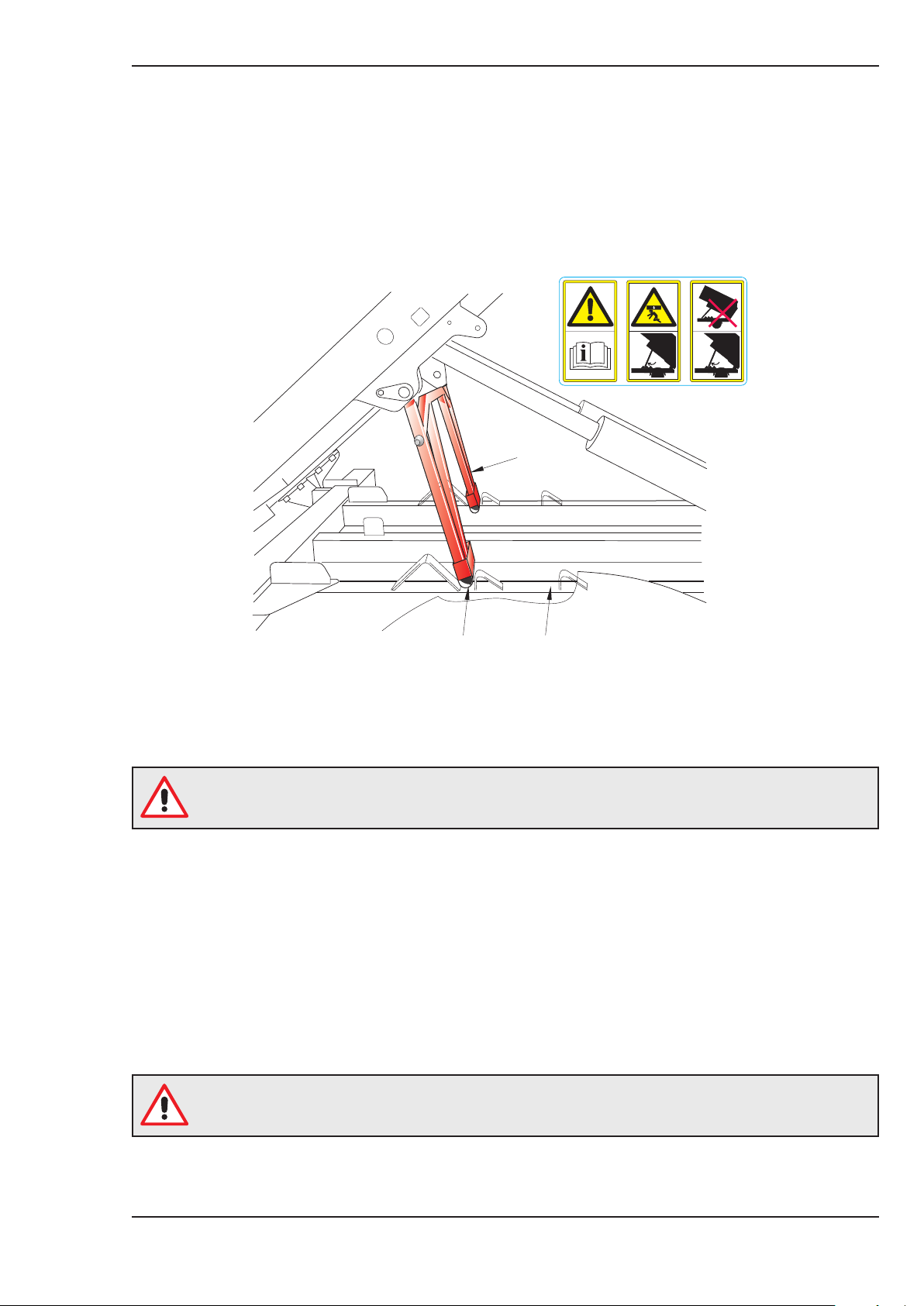
To Tip the Load
Open the rear door by pressing DD-A and F.
Raise the body by pressing switch DD-C and F, this will cause the body prop ‘A’ (painted red) to
index into the locking step ‘B’ on the subframe. Ensure the prop has located against the step.
(A)
Johnston Sweepers Limited
RTOG. 009-5
(B)
After the load discharge and whilst the body is raised, wash out the intake tube, filter screen (Item
15, Fig.1), SepaVac unit (Item 18, Fig.1) and the rear door with the washdown hose or Supawash
hand lance (whichever is fitted) to remove any ‘caked’ material.
A bang should be heard when the rear door locking pin locates in the latch plate.
To Lower the Body
Ensure that the chassis air system is fully charged so the body prop delatch system will operate
correctly and prevent any possible damage to the release mechanism.
Press DD-C and F to raise the body so that the body prop can clear the locking steps.
Press buttons DD-D, E and F to lower the body.
Press button DD-B and F to close the rear door.
(C)
Page Issue A
A warning light (B7) on the switch panel illuminates and a bleeper will sound when the
body is raised or not fully lowered.
Chapter - Operation
OG3:9
Page 28
RT655 Operator’s Guide
Emergency Discharge Pump
In the event of an auxiliary or electrical system malfunction , the body can be raised by:-
- Turning on the chassis engine
- Turn on the sweepger ignition
- Check the green light on the discharge pendant
- Push buttons DD-C and F to raise the body so that the body prop can clear the locking steps
NB: This system can also be used to open the rear door. So is applicable for discharging loads
when in dusty environments.
End of Day Cleaning Routine
Safety Notice
Sharp objects warning - there can be a risk of injury from sharp objects such
as discarded hypodermic needles becoming lodged in the sweeping system.
The use of ‘needle stick gloves’ is recommended when changing brushes,
using the Wanderhose/Littasnatch and when cleaning out the machine.
The body flush out hydrant hose connection (item 22, Fig. 1) is provided and when connected will
flush out the various ducts and hoses.
1. With the nozzle hood (pick-up hood) in the stowed position, start the auxiliary engine and
increase the speed to approximately 1500 rpm.
2. Slowly turn on the hydrant water. This procedure will automatically wash out the internal body,
ductwork and SepaVac (dust separator), the blower housing, the blower fan and the nozzle
pressure hose, along with the underside of the nozzle hood and the nozzle suction hose.
3. After about 5 minutes, lower the hood to the ground and continue the flushing cycle. This will
collect all the water into the body flushing the dirty water from the surrounding areas.
4. Turn the hydrant water off. Raise the nozzle hood (pick-up head) to the stowed position and
open the rear door to drain off the waste water.
5. Whilst the body is in the raised position, stow on the auto prop. Turn the hydrant water back
on to wash out the internal SepaVac cover that will have hinged clear of the fan inlet to allow
the fan side of the SepaVac to be cleaned.
6. The waste water will run through the SepaVac discharge covers to thoroughly clean the total
body fan system.
7. Leave the rear door partially open to allow moisture to escape and prolong the life of the rear
door seal.
OG3:10
Chapter - Operation
Page Issue A
Page 29

RT655 Operator’s Guide
SWEEPING IN COLD TEMPERATURES
Operating Temperature 0°C to +5°C
For sweeping in cold conditions above freezing, it is possible to use the water system providing the
machine has been left in a warm garage overnight.
Care must be taken to ensure water sprayed onto the road does not freeze.
Do not use full suction capacity above 1600 engine rpm as the air speed up the nozzle could cause
the water to freeze.
Operating Temperature 0°C to -15°C
It is possible to use the machine for short periods without water in the tanks.
Sweeping can be carried out using low to medium suction 1200 - 1500 engine rpm.
Please note that some dust may be emitted from the fan outlet, and premature wear may be
experienced on some components.
Johnston Sweepers Limited
Page Issue A
Chapter - Operation
OG3:11
Page 30
RT655 Operator’s Guide
COLD WEATHER PRECAUTIONS
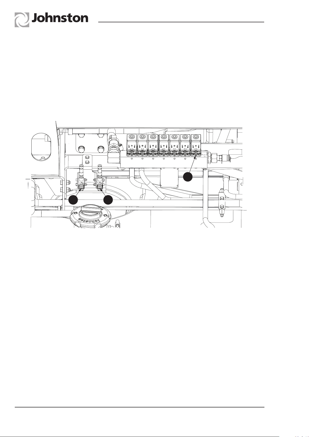
To avoid the possibility of frost damage to the water system when the machine is left during cold
weather, it is essential to drain the system adequately. Open the drain taps T Items 26 & 27,
Fig. 1. When the water draining from the taps stops:
1. Start truck engine and auxiliary engine and raise the body.
2. Operate the low pressure and Supawash water pump (if fitted) with the manual overrides
(B) open and the Supawash spraybar (if fitted) on. Manual override indicator (C).
The Supawash pump will stop when the water low level light illuminates.
C
B A
RTMA.056
3. Open the Pressadrain tap (A) for 1 minute to provide air to purge the water from each jet.
4. Open the washdown hose and purge the water from the hose and close (machines without
Supawash only).
5. Operate the Supawash hand lance until air is emitted from the jet.
6. Operate the Supawash spraybar in turn. Turn off the Pressadrain, Supawash and stop the
auxiliary engine.
NB: Remember to refit the red drain plug in the filter and turn off all the manual overrides (B) and
Supawash taps on the next shift.
OG3:12
Chapter - Operation
Page Issue A
Page 31

RT655 Operator’s Guide
Johnston Sweepers Limited
CHAPTER
4
Optional Equipment
Table of Contents
Subject Page
Options
Supawash OG4 : 2
Wanderhose OG4 : 4
Emergency Discharge OG4 : 6
Emergency Hood Lift OG4 : 6
Page Issue A
Chapter - Optional Equipment
OG4:1
Page 32
RT655 Operator’s Guide
C2OG.075-2
C2OG.076
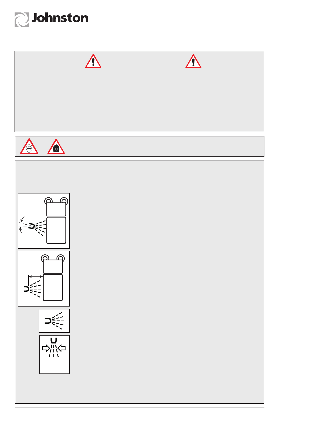
SUPAWASH OPTION
Safety Precautions
● Care MUST be taken not to damage sign written areas when cleaning. See special notes
for cleaning vehicles with vinyl livery below.
● ALWAYS keep pressure equipment in good condition and regularly maintained,
particularly at joints and unions.
● The use of safety goggles is recommended in case of deflected spray/debris.
● NEVER direct a high pressure nozzle at the skin as the fluid may penetrate the
underlying tissue etc. and cause serious injury.
Eye protection and ear defenders are recommended when working
around the machine
Special notes for cleaning vehicles with vinyl livery or reflective markings
The supawash handlance or similar can be used for cleaning areas of the vehicle with
vinyl or reflective markings subject to the following precautions being taken
● The spray angle should be maintained between 90 and 75
degrees to the panel
90°- 75°
● The nozzle distance should be greater than 1 metre minimum
from the panel
1M
● The spray pattern should be a wide fan pattern
OG4:2
● The nozzle pressure should be 80 bar (1000PSI) max
● The water temperature should not exceed 60 ºC
80 bar
(1000 psi)
● Do not use acid or solvent cleaning solutions û
Alternative Methods
● Do clean with a sponge or soft cloth using cold or warm water
with a soap or detergent, followed by a cold water rinse
Chapter - Optional Equipment
Page Issue A
Page 33
RT655 Operator’s Guide
DESCRIPTION
Johnston Sweepers Limited
B
A
D
E
F
C
RTOG. 014-4
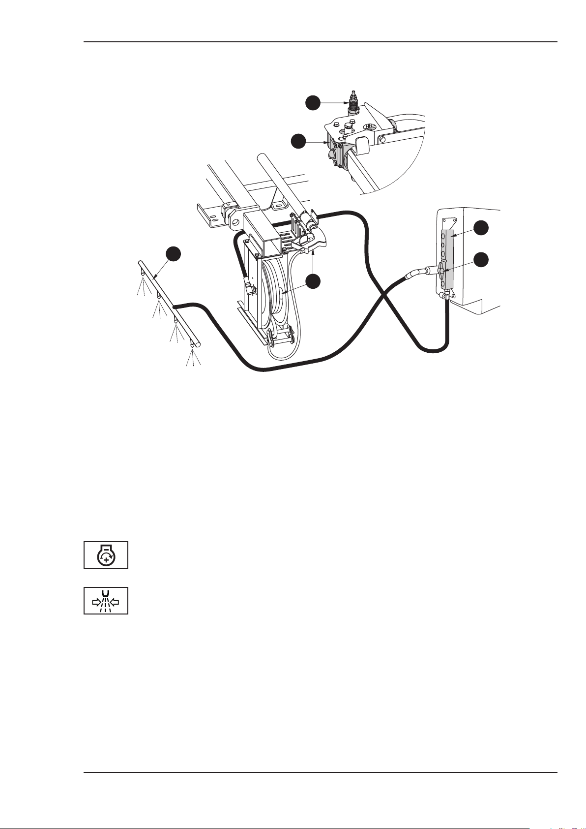
The equipment comprises a hydraulically driven high pressure water pump (A) and unloader valve
(B) fitted to the subframe centre crossmember. A hand lance with 15 metres of hose on a recoiling
reel (C) mounted to the subframe rear crossmember and a manifold (D) attached to the nearside
water tank. An optional front spraybar (E) is available with isolating valve (F). The spraybar can be
used during sweeping operations to jet wash the road prior to, or after, sweeping.
The hand lance can be used to clean down the vehicle at the end of a shift or day’s work.
OPERATION
The auxiliary engine must be running and the throttle adjusted to 2000 rpm.
Press switch (M1) on the switch panel to activate the water pump.
HAND LANCE - Remove the lance (Item 37, Fig. 1) from its holster adjacent to the hose reel. Two
jets are provided at the nozzle; a fan spray and a pencil jet. To change between
jets the trigger should be released and the gun rotated through 180°, this will
automatically select the alternative jet.
SPRAYBARS - The front bar is activated by an isolating valve located on the near side water tank
(D). The valves should be closed when the hand lance is to be used.
NB : The Supawash pump will not operate if the water tank is nearly empty. Low
level water switch illuminates in the cab when this occurs.#
Page Issue A
Chapter - Optional Equipment
OG4:3
Page 34
Sharp objects warning - there can be a risk of injury from sharp objects such
as discarded hypodermic needles becoming lodged in the sweeping system.
The use of ‘needle stick gloves’ is recommended when changing brushes,
using the Wanderhose/Littasnatch and when cleaning out the machine.
Ear defenders are recommended when working around the machine
Eye protection is recommended when working around the machine
PREPARATION
RT655 Operator’s Guide
Safety Notice
WANDERHOSE OPTION
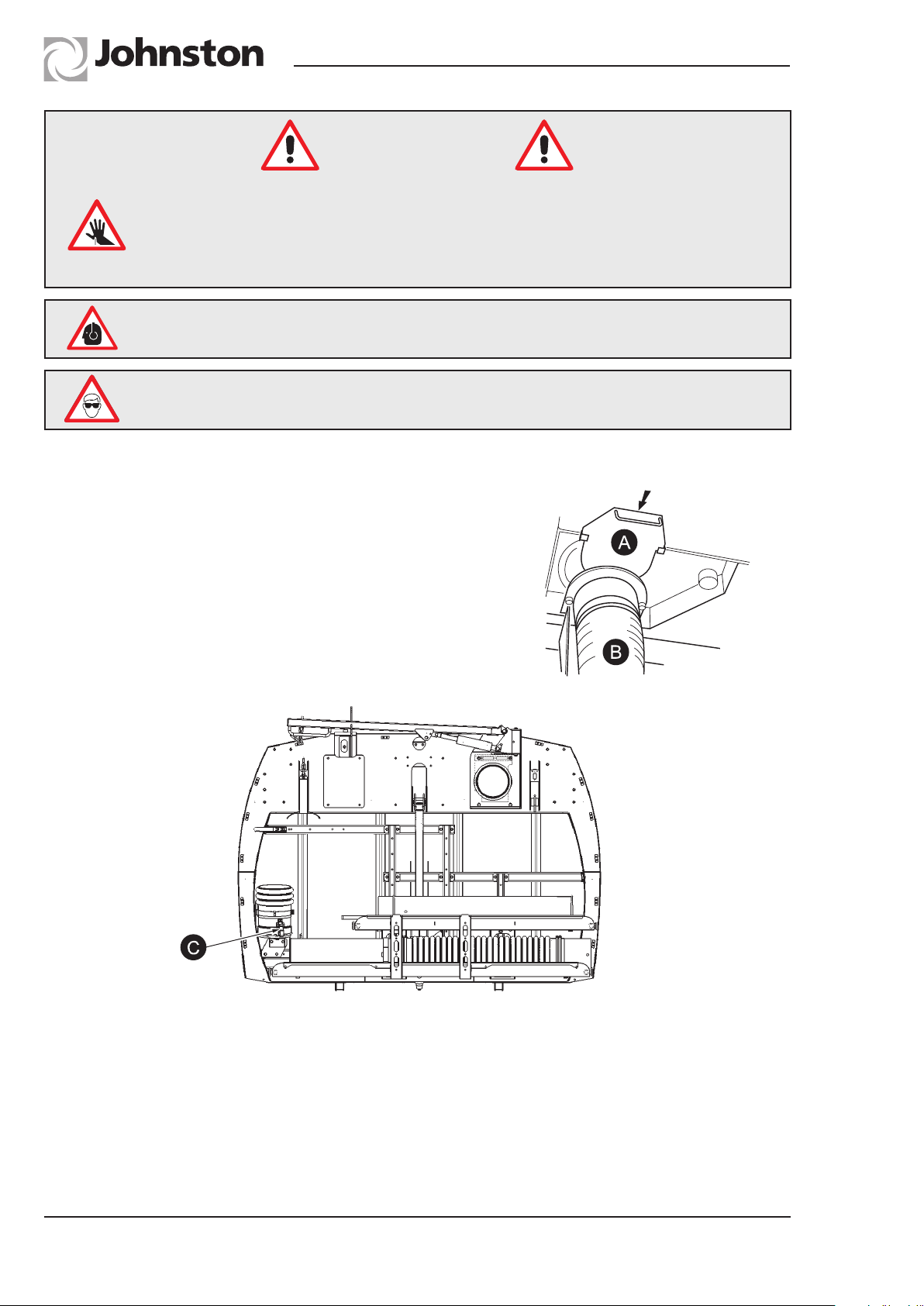
Before using the Wanderhose it is necessary to blank off
the intake hood ducting to prevent air passing into the
body via the hood. The duct has to be manually blanked
using the blanking plate. This plate (A) is stowed on the
underside of the body adjacent to the intake duct and
must be positioned on the seat at the top of the flexible
nozzle duct (B). The body must be raised slightly to
position the plate, and lowered afterwards.
RTOG. 030
RTOG. 040
OPERATION - Once the intake duct(s) have been blanked:
1. Before using the Wanderhose, always fully open the VEG gate.
2. Raise the body and blank off suction duct
3. Switch the ECO override button, so full throttle RPM is available
4. Unclip the Wanderhose end from the option frame stowage
5. Clip on extension hose
6. Set engine RPM as required
7. Use powaboom controls to release Boom from Stowage and manoeuvre
OG4:4
Chapter - Optional Equipment
Page Issue A
Page 35
RT655 Operator’s Guide
The hose and boom are hydraulically lifted and can be used to the left or right hand side of a
stationary vehicle with a single operator. With a second operator, the hose can be used whilst
the vehicle is moving slowly along. The hose operator should position them self at the rear of the
vehicle, moving onto the footpath to clean around obstructions as they are encountered. Additional
extensions can be added to the equipment for cleaning deep drains, gullies and catchpits. The
Wanderhose can also be employed effectively on surface flood water.
Note :
The correct operation of the Wanderhose is achieved by holding the pipe just above the water or
debris being picked up.
Johnston Sweepers Limited
WANDERHOSE - CONTROL
The Wanderhose is assembled on the previous page.
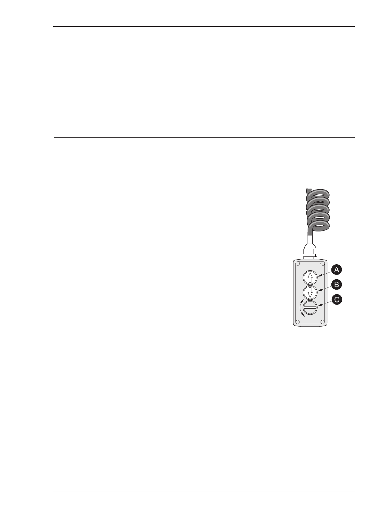
When using the controls for a single user:
1. Apply the vehicle handbrake.
2. Press button A to raise the unit from its stowage position
and rotate to the working position.
Press button B to lower as required.
Switch C controls the suction as follows;
Turn clockwise to increase engine speed, counter
clockwise reduces speed.
John Deere electronic. Turning clockwise will
increase engine speed from preset value (on the
engine speed control in the cab) to maximum
speed, releasing it will return speed to the preset
value.
RTOG. 025
Page Issue A
Chapter - Optional Equipment
OG4:5
Page 36

RT655 Operator’s Guide
EMERGENCY DISCHARGE
In the event of an auxiliary engine malfunction, or discharging a load, tipping can be achieved as
follows.
1. Apply vehicle brake and leave the chassis engine running.
2. Push sweeper ignition
3. Use discharge pendant to raise body or open rear door
EMERGENCY HOOD LIFT
To raise the hood without the auxiliary engine running, or if the engine malfunctions when the hood
is in the working position, the following routine should be adopted to raise it.
1. Apply vehicle handbrake
2. Switch sweeper ignition off and then turn on
3. Check hood switch is in its off position
4. Push in the third position the Hood Hop button, until the hood is fully raised
OG4:6
Chapter - Optional Equipment
Page Issue A
Page 37

RT655 Operator’s Guide
Johnston Sweepers Limited
CHAPTER
6
Routine Maintenance
Table of Contents
Subject Page
Safety Precautions
Safety Precautions OG6 : 2
Maintenance Schedules
Maintenance Schedules OG6 : 3
Equipment Adjustment / Maintenance
Gutter Broom Adjustment OG6 : 6
Gutter Broom Replacement OG6 : 7
Pick-up Hood OG6 : 8
Spring Adjustments OG6 : 9
Suction Fan Impeller and Casing OG6 :10
Filter Screens and Roof Duct OG6 :10
Water Filter - Cleaning OG6 :11
Auxiliary Engine OG6 :12
Cold Weather Precautions OG6 :12
Filter Regulator Unit OG6 :13
Air Cleaner Restriction Indicator OG6 :13
Air Cleaner OG6 :13
Fuel Lift Pump OG6 :13
Alternator and Water Pump Belt Tensioning OG6 :14
‘Z’ Drive Gearbox OG6 :14
Hydraulic Reservoir OG6 :14
Cylinder Maintenance OG6 :14
Supawash Pump OG6 :15
Lubrication
Lubrication Diagram and Approved Lubricants OG6 :16-17
Page Issue A
Chapter - Routine Maintenance
OG6:1
Page 38

RT655 Operator’s Guide
Safety Precautions
DO NOT
● Work on or around the engine whilst it is running except to adjust idle settings.
● Remove engine radiator cap when the engine is hot, without first covering the cap
with a cloth. Release it slowly, otherwise there is a risk of being scalded by escaping
coolant.
● Touch any part of the engine exhaust system without first allowing it to cool
sufficiently.
● Drain engine oil until it has cooled, to avoid scalding.
● Work on the braking system without first discharging the accumulators by 60 full
applications of the foot brake.
● Disconnect hydraulic or water pipes whilst the engine is running.
● Approach fan inlet or outlet whilst the fan is running.
ALWAYS
● Ensure the machine is standing on firm, level ground and there are no obstructions
above or to the rear before raising the hopper.
● Ensure that the body is resting on the body prop before working underneath the
raised hopper.
● Keep hands, loose clothing, hair etc, well clear of moving parts.
● Use approved safety platforms/gantries when working above ground level. Get a
second person to check periodically when only one person is working on access
equipment or inside the body.
● Ensure the operators and service personnel are fully conversant with the controls
and their operation.
● Disconnect the vehicle battery when working on the electrical system or when
carrying out any welding on the vehicle.
● Remove ignition key when working on the vehicle. Ensure all personnel are clear of
the vehicle before restarting engine.
● Ensure all guards and covers are refitted after servicing.
● Disconnect or isolate the air system before working on any pneumatic items.
OG6:2
Chapter - Routine Maintenance
Page Issue A
Page 39
RT655 Operator’s Guide
Johnston Sweepers Limited
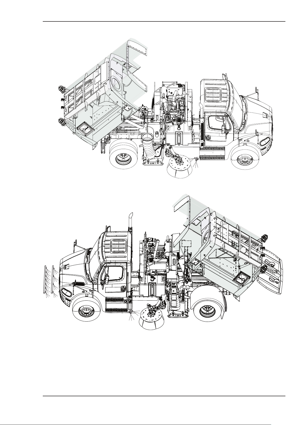
MAINTENANCE SCHEDULE
(OG6:4 - OG6:5)
Key
D = Daily W = Weekly A = 500 Hours B = 1000 Hours C = 12 Monthly
Attention is drawn to the recommendations for servicing in the Auxiliary Engine Handbook.
RH Sweep machine shown
Page Issue A
Chapter - Routine Maintenance
OG6:3
Page 40

RT655 Operator’s Guide
MAINTENANCE SCHEDULE
DAILY MAINTENANCE - These can be carried out by a trained operator.
Check the following items:
1 Oil level in hydraulic reservoir - top up if required.
2 Auxiliary engine oil level - top up if required.
3 Auxiliary engine radiator level - top up if required.
4 Auxiliary engine radiator is not obstructed.
5 Filter state indicator - service air filter if red.
6 Mesh screen in body is clean and fitted correctly.
7 Mechanical damage to brush gear and report damage to Supervisor.
8 Brushes for adjustment and wear - adjust or replace as required.
9 Spray jets for correct operation - clean if necessary.
10 With the nozzle (pick-up head) lowered, check nozzle (pick-up hood) suspension springs
for proper tension. The springs should be tensioned just enough to allow the skids to lightly
contact the road surface. If the spring tension is inadequate, the hood will drag heavily on
the road surface, resulting in premature skid wear.
11 Check channel brush(es) (gutter brooms) for proper adjustment. The brush angle should be
set using the adjuster bolts so that only about 120o of the circumference towards front and
kerbside is in contact with the road.
12 Oil/water/fuel leakages.
13 Chassis items as recommended in chassis manufacturer’s handbook.
♠WEEKLY MAINTENANCE
Attend to/check the following:
1 Oil level in ‘Z’ drive gearbox - top up if required.
2 Fan/engine bay is clean of oil etc.
3 Auxiliary engine vee belt tensions.
4 Suction fan impeller, wear plate hood and optional intake flap for wear, renew if necessary.
5 Routing of electrics and hydraulic services for chafing.
6 Lubricate all grease points - see lubrication chart later in this chapter.
7 Water pump suction filters.
8 Oil level and condition in Supawash pump if fitted.
OG6:4
Chapter - Routine Maintenance
Page Issue A
Page 41

RT655 Operator’s Guide
Johnston Sweepers Limited
MAINTENANCE SCHEDULE (Continued)
♠Service A - every 500 hours
1 Change auxiliary engine oil and renew filter.
2 Clean fuel pre-filter bowl (John Deere).
3 Renew the fuel filter element.
4 Renew auxiliary engine air cleaner elements
5 Check auxiliary engine throttle control and engine idle for correct operation.
6 Clean duct in body roof.
7 Check the fluid flywheel oil level.
8 Check auxiliary engine coolant concentration gives -39°C frost protection.
9 Check Supawash pump (if fitted) for correct operation of jets and any plunger seal leakes.
Service as necessary.
♠Service B - every 1000 hours
1 Carry out 500 hour service; plus
2 Renew hydraulic return filter element.
3 Renew water pump suction filters.
4 Check valve clearances on the auxiliary engine if applicable.
5 Check security of sweeping equipment to chassis.
♠Service C - 12 monthly maintenance - or every 2000 hours
1 Carry out 1000 hour service; plus
2 Drain hydraulic reservoir.
3 Clean suction filter and refill hydraulic reservoir.
4 Drain and refill ‘Z’ drive gearbox.
5 Replace engine fan/alternator belts.
6 Drain and refill Supawash pump (if fitted).
Used oils and filters should be disposed of in accordance with local waste disposal
regulations.
Page Issue A
♠These procedures should be carried out by qualified service personnel.
Chapter - Routine Maintenance
OG6:5
Page 42
RT655 Operator’s Guide
EQUIPMENT ADJUSTMENT / MAINTENANCE
Introduction
This chapter highlights some of the basic adjustment and maintenance procedures required to keep
the machine performing efficiently.
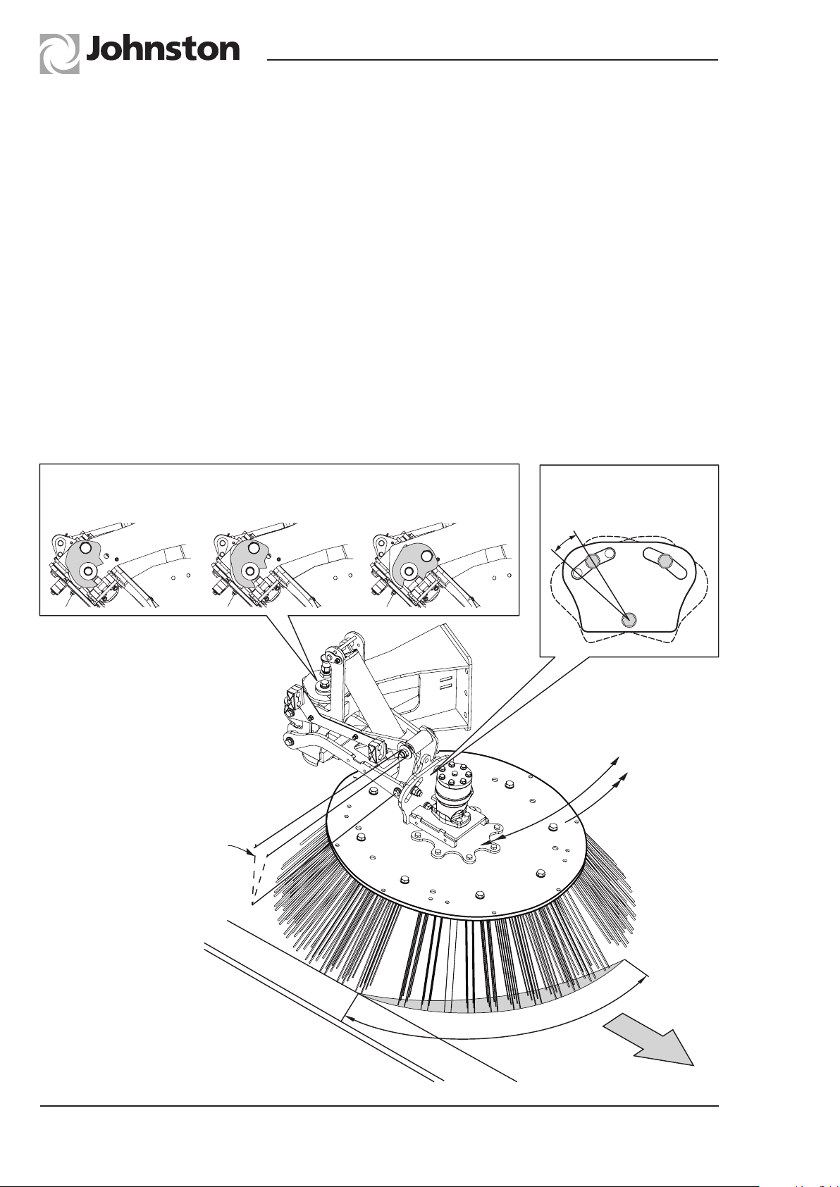
Gutter Broom Adjustment
This section highlights the Gutter Broom adjustment. The machine can sweep with single brush,
kerb (nearside) or offside (road side) or simultaneously brushes working. When the offside is
deployed its important to set the brush close into the chassis by using either the mechanical stop
or the Variabrush control. Maintain a visual eye on its position when sweeping so as to avoid other
road traffic.
The Gutter Broom(s) are supported on a forward facing arm that is controlled by its lifting cylinder,
which allows for ‘float’ and ‘light sweep’ (Powasave) ground pressure control. The Gutter Broom
head drives itself out to the stopped position (variable) by the action of the rotating brush on the
ground.
Settings for Mechanical Stops
Narrow Standard Extended
'B'
'B'
Dip Angle Setting Can be
set between 0-10 degrees
'C'
Brush Angle
Setting 0-15
'A'
Variabrush
In - Out Control
Auto
“Kick-Back”
ESOG.017
OG6:6
Chapter - Routine Maintenance
120°
Sweep
Direction
Page Issue A
Page 43

RT655 Operator’s Guide
The brush angle should be set using adjustment (C) and (D) so that only about 120o of the
circumference towards the front kerb is in contact with the road.
If a ‘light sweep’ brush pressure is set, then the brush may not position itself outwards. In this case
reset the ‘light sweep’ regulator for a lower pressure. The brush pressure can be adjusted by the
Variabrush feature (A) allowing the brush to be brought forward, (recommended for the off side
brush when deployed) or outwards to position the brush for its best sweeping position. This is a
very useful feature when sweeping between trees, driveways and other items, as you can move the
brush quickly in and out to any position, maintaining the chassis in a straight line.
The brushes have automatic ‘kick-back’ should they come into contact with an object during the
sweeping mode. The head does have a ‘dip angle’ to maintain optimum brush angle. This can be
adjusted as shown below.
Channel Brush Replacement
Johnston Sweepers Limited
Safety Notice
Sharp objects warning - there can be a risk of injury from sharp objects such
as discarded hypodermic needles becoming lodged in the sweeping system.
The use of ‘needle stick gloves’ is recommended when changing brushes,
using the Wanderhose/Littasnatch and when cleaning out the machine.
Isolate the chassis engine. Turn off the air at the filter regulation unit (item 2 on lubrication diagram).
Pull the channel brush arm out to the working position.
The brush segmented heads are held to the top plate by 2 off 5/8” bolts per segment (8 in total), or
4 off 3/8” bolts (16 in total). Loosen these bolts and remove each segment at a time, replacing with
new filled segments as you go.
In this way the brush top drive plate will remain level during the removal and refitting. Whilst refitting
the brush segments check to see that no wire or tine material has been caught up under the brush
top plate. Remove as required.
Good quality brush segments are recommended.
Ensure the auxiliary engine is not running and isolated before maintenance or
replacement is attempted.
Page Issue A
Chapter - Routine Maintenance
OG6:7
Page 44
RT655 Operator’s Guide
Pick-up Hood
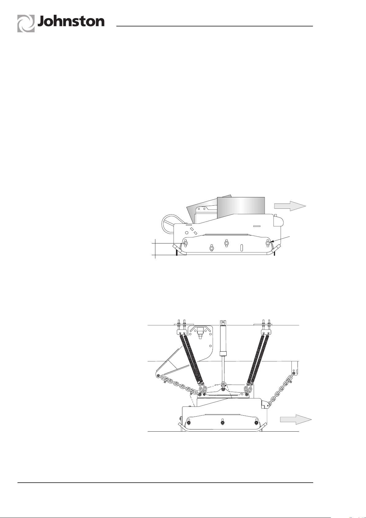
The pick-up hood is towed by 4 chains positioned at the front and rear. This allows the machine to
sweep forwards and backwards, as the pick-up hood will be guided during the travel mode. The
pick-up hood is lifted by two hydraulic cylinders, one either side that connect directly to the head.
The positive hydraulic check valve system will support the nozzle in the stowed position during
transit. Additional chains are located at the lift point and anchored to the chains support to prevent
excess sideways movement during sweeping.
Pick-up Hood Skate System
The pick-up hood runs on adjustable side skates that are carbide faced to improve wear. The water
system provides for front under skate lubrication on dry days for the carbide faces. These skates
are non handed and are mounted to the hood side plates by three locking nuts and one bolt that
locates into the rear side assembly skate.
The initial setting of the skate is on
the centre line of the skate side slots
and the skate can be lowered as it
wears by moving the skate down into
the slots. Re-tighten firmly the three
locating nuts and the locating bolt. The
skate adjustment is mainly for wear, but
you can set the front of the pick-up hood
higher to allow for a larger opening when
sweeping bulky items such as leaves.
The rear of the side skate should retain
the rear setting of the internal rubber so
as to maintain a close contact to the road
surface.
Sweep
Direction
Locking
nuts
RTNZ.001
Pick-up Hood Suspension
The pick-up hood is suspended on eight
springs, four each side, two at the front
and two at the rear. These are set to
reduce the weight of the pick-up hood
on the ground and will reduce marking
of the ground surface. The initial setting
ex-factory should suit most conditions
and provides for a light (downward) force
to seal the hood via its internal flaps whilst
working under the suction pressure.
Sweep
Direction
RTNZ.002
OG6:8
Chapter - Routine Maintenance
Page Issue A
Page 45
RT655 Operator’s Guide
RTNZ.003
Heavy Medium Light
The settings can be
30-50mm.
The factory setting is
30-35mm.
Johnston Sweepers Limited
Spring Adjustments
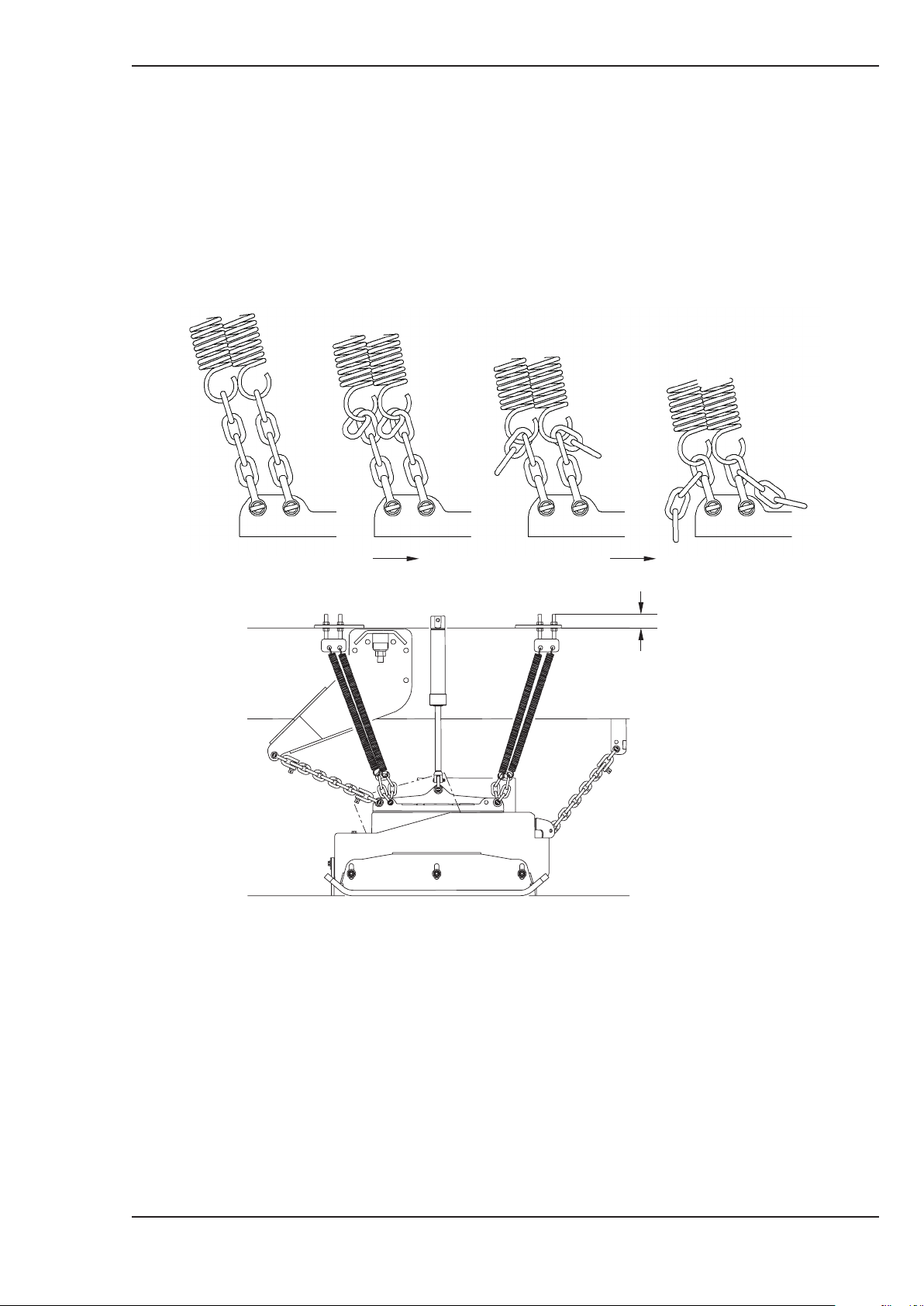
The springs locate to the hood via chains which allow for adjustment by resetting the chain length.
The chains length can be set longer by locating the spring into a longer chain loop to create a
heavier force to the ground where needed.
The machine ex-factory is set for light sweeping with one chain link spring connection. Once set this
does not normally need to be adjusted.
By moving the spring support upwards to 50mm you can tension the springs to fine adjustment.
The initial factory setting is 30 - 35mm. Both sides on the pick-up hood should be adjusted in the
same way, although subject to road camber you might want to alter these settings to suit conditions.
Always try to set the pick-up hood to the lightest ground pressure.
Page Issue A
Chapter - Routine Maintenance
OG6:9
Page 46
RT655 Operator’s Guide
RTOG. 024
Suction Fan Impeller and Casing
In operation the impeller and casing can be subjected to wear in the form of erosion
Ensure the auxiliary engine is not running and isolated before fan maintenance
resulting from dust or small abrasive particles passing through the fan system and must
be inspected as instructed in the Weekly Maintenance Schedule.
In cases where excessive dust could pass through the system, these inspections should be made
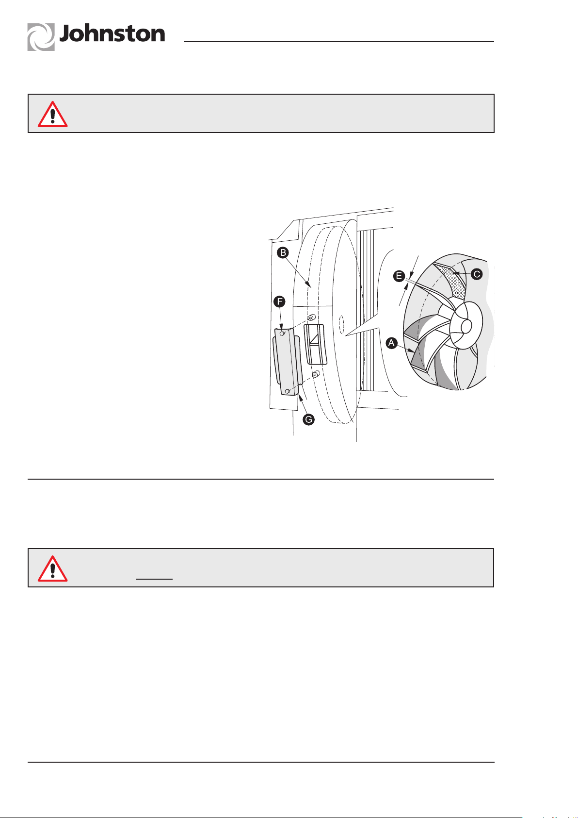
more frequently, the blades should be clean of any debris (C) to prevent dirt build up and premature
failure due to vibration.
Remove the 2 setscrews (F) and remove
the inspection plate (G). The impeller blades
can be seen through the inspection port and
the blades cleaned with a scraper (part no.
283665-1) if required.
If the impeller is subjected to excessive wear,
disintegration could occur whereby the front
shroud plate detaches itself from the driving
plate as a result of the high rotational forces
within the component. Any wear occurring to
the impeller is usually shown up as a thinning
of the blades generally in a broad wear pattern
(A). Once apparent thinning of the impeller
blades is observed, the component must be
replaced when any blade thickness (E) is
less than 2mm. If perforation of the fan case
is observed (B) due to wear erosion, this
component should also be replaced to prevent
pollution of the fan compartment with dust.
Refit the inspection plate securely after inspection / cleaning.
or replacement is attempted.
Filter Screens and Roof Duct
The body filter screen (Item 15, Fig.1) and roof duct must be kept clean, otherwise suction
performance can be affected. The screen can be cleaned in situ, but it is preferable to remove it.
The fan impeller is finely balanced as an assembly in manufacture.
NEVER remove or replace the hub, or carry out repairs to it.
To remove, release the linch pin, which will allow the screen to swing down, disconnect the air pipe
to the mesh shaker unit if fitted. The screen can then be lifted out of the hooks on the rear sloping
panel for thorough cleaning. Also hose out the roof ducts to ensure they are clean while the filter
screen has been lowered.
OG6:10
Chapter - Routine Maintenance
Page Issue A
Page 47
RT655 Operator’s Guide
Johnston Sweepers Limited
Ensure the screen is lowered slowly. If the mesh is allowed to ‘free fall’ and
bounce off of the baffle, there is a possibility of it being dislodged
from the hinge point.
With the screen removed and the body raised and resting on its prop, clean out all debris from the
roof duct which runs along the top of the body, using a hose and broom. Care should be taken not
to get water in the fan case.
When refitting the screen, ensure it is a close fit against the mating faces. Adjustment is provided
so that debris is prevented from entering the fan. Replace the linch pin.
Water Filter - Cleaning
The water filter (Item 27, Fig. 1) for the low pressure pump is on the near side of the machine. The
filter is equipped with an integral shut off valve to prevent the water tank from draining should the
filter need dismantling for cleaning whilst there is still water in the tank.
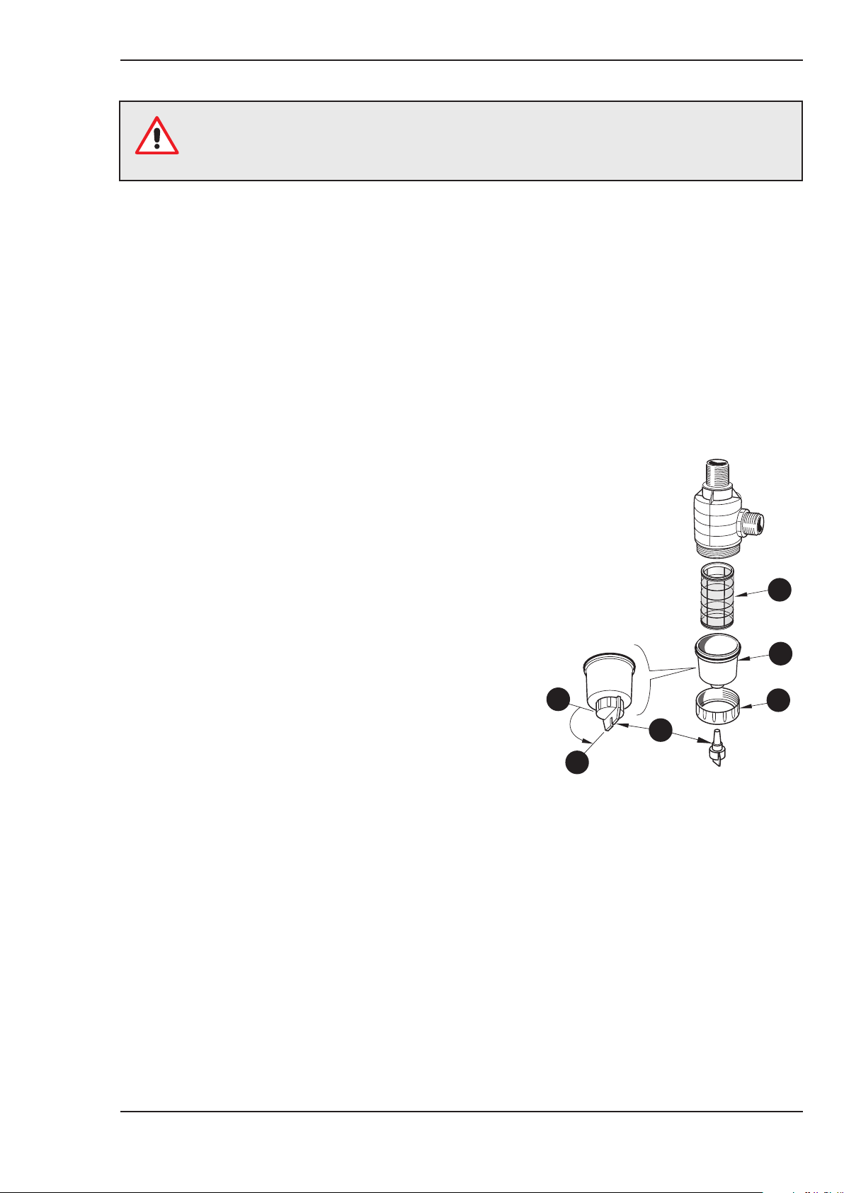
1 Before dismantling the filter, activate the shut off valve
actuator (A) located on the bottom of the filter. It has
a bayonet type mechanism. Press up and turn anticlockwise to position (i) to shut the valve.
2 To access the filter element, unscrew securing ring (B)
and remove body section (C), complete with shut off
valve. The filter element (D) can now be withdrawn.
3 Clean the element by flushing with clean water or an
air line from the inside out. Visually inspect the element
for damage and replace if necessary.
4 When reassembling the filter, special care should
be taken to ensure that the filter element is correctly
(squarely) located in the filter body before tightening
the securing ring.
5 Refit the shut off valve actuator. Press up and turn
clockwise to position (ii) to open the valve ready for
use.
D
C
ii
o
90
A
B
i
RTOG. 006-1
If Supawash is fitted there will be additional filter that feeds the Supawash pump.
Page Issue A
Chapter - Routine Maintenance
OG6:11
Page 48
RT655 Operator’s Guide
AUXILIARY ENGINE
Safety Notice
Ensure the auxiliary engine is not running and isolated before fan maintenance or
replacement is attempted.
G
D
A
H
E
RTOG. 043
B
Engine Oil
OIL LEVEL CHECKING
Check daily. The level can be checked with the body raised. Ensure the body prop is in place.
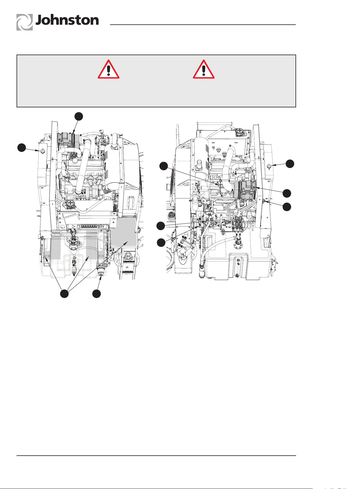
The dip stick (A) is located on the right hand side of the engine and is reached by standing on the
walkway (B). Extreme care must be taken when working from the walkway, particularly in wet
conditions.
C
D
G
F
OIL CHANGING
At the frequency specified in the Maintenance Schedule. Oil specifications are shown in the
lubrication diagram - see later in this chapter. The oil is best drained whilst warm via the remote
drain plug (C).
Cold Weather Precautions
The cooling system (D) must be filled with equal quantities of antifreeze and water to maintain a
minimum concentration of 50%, i.e. -39°C. Any top ups must therefore be done with a 50% mixture
of antifreeze and water. The concentration level should be checked at the 500 hour service interval
as failure to observe this can cause corrosion of the engine block.
OG6:12
Chapter - Routine Maintenance
Page Issue A
Page 49
RT655 Operator’s Guide
Johnston Sweepers Limited
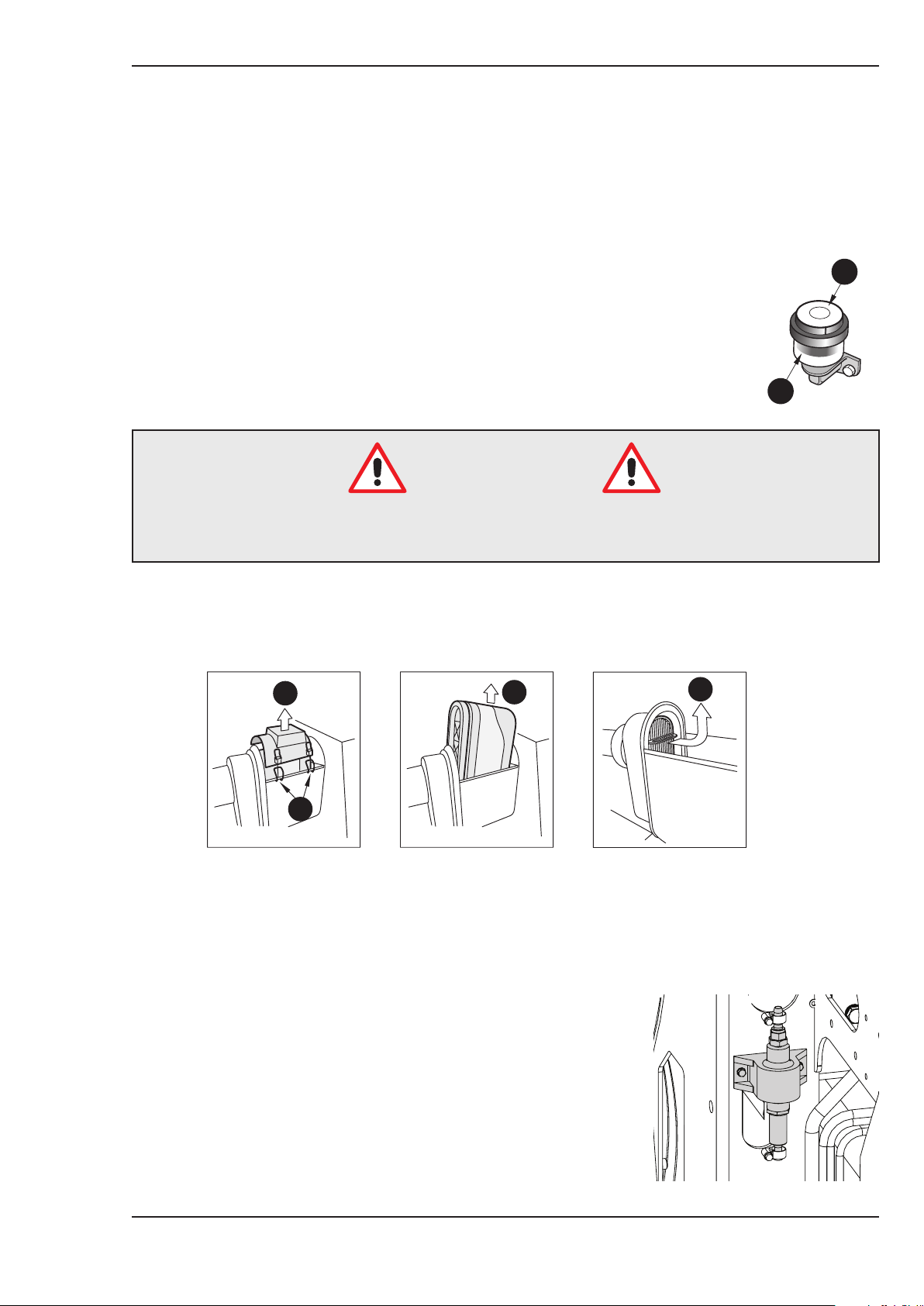
Filter Regulator Unit (E)
The filter regulator unit comprises a combined air filter/pressure regulator. The air filter can be
manually drained by pushing up the bowl drain tube. The air is isolated and drained by pressing
the red gate valve on the unit.
Air Cleaner Restriction Indicator (F)
B
A filter restriction indicator gives a positive indication of when the air cleaner
element needs attention and so eliminates haphazard servicing. It should be
remembered that the indicator does not show the amount of dust present in the
dust cap. When the air cleaner requires servicing the red warning indicator (A)
will lock up. After servicing the indicator should be reset by pressing button (B).
It will now show black.
A
RTOG. 023
Safety Notice
Ensure that the elements, lid and clips are correctly fitted and that the air intake
pipe and clips to the engine are in good condition and fully sealed.
Air Cleaner (G)
The air cleaner should only be serviced when the restriction indicator is showing red, the air cleaner
elements must be cleaned and replaced at the intervals given in the Maintenance Schedule.
B
C
D
A
RTOG. 019-1
Lift the retaining clips (A) to remove the lid (B). Remove the main filter element (C) by first pushing
the filter down and tilting it towards the radiator and then lift it out. There is a small safety element
(D) within the main filter body, this should be replaced every third time the main element is changed.
Re-assemble the air cleaner ensuring all parts are correctly positioned and fitted. Refit plug (A)
ensuring a good seal against water ingress.
Fuel Lift Pump (H)
The John Deer engine requires an additional electrical lift pump
for the fuel.
The lift pump is constantly self-priming, and has a non-return
valve fitted to stop dry priming. The pumps are voltage related,
12V (7031889) 24V (7044661). 12V shown.
When the chassis ignition is on, the pump will tick as it is
constantly pumping. If it is not ticking, turn the ignition off, wait 1
minute, and retry. If it is still silent, and the engine is not working,
the pump has failed. Replace the pump.
Page Issue A
Chapter - Routine Maintenance
OG6:13
Page 50
RT655 Operator’s Guide
Alternator and Water Pump Belt Tensioning
The John Deere engines have an automatic belt tensioner so should not require adjustment unless
the belt is replaced - see engine manufacturers handbook for setting information.
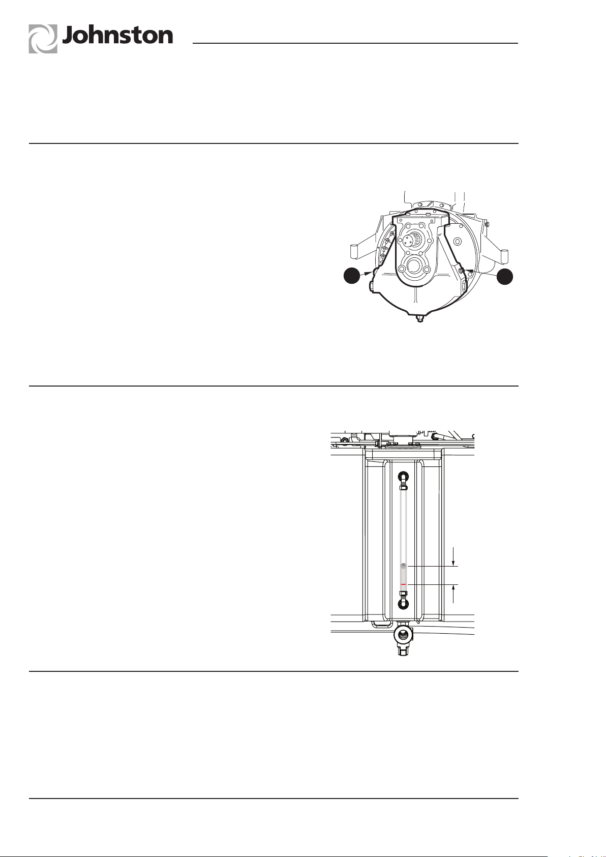
‘Z’ DRIVE GEARBOX
OIL LEVEL CHECKING
The level plug (B) should be removed and filled to the bottom
of the thread. The window (A) allows a quick reference and,
if the oil level is not visible on the window, the level requires
topping up.
OIL CHANGING
Change the oil after the first 50 hours operation, thereafter at
1600 hour intervals or 12 monthly whichever is the sooner.
Oil specifications are shown in the lubrication diagram - see
this chapter. The oil is best drained whilst warm via the remote
drain plug (G) located on the engine pack rear valance. See
the illustration in the preceding auxiliary engine oil chapter.
HYDRAULIC RESERVOIR
Checking Oil Level
Raise the body and engage the body prop in its
highest position. The level (A) should be 10mm
above the lower red line (B) on the gauge. It is
important that the correct level is maintained
as under filling can adversely affect the heat
dissipation rate of the oil, whilst over filling can
cause oil to overflow when the body is lowered.
The recommended oil is shown in the lubrication
chart at the end of this chapter.
A
RTOG. 021
A
B
10mm max
B
RTOG. 044
CYLINDER MAINTENANCE
Periodically inspect the cylinder rods for damage, blemishes or build up of material such as tar,
cement, paint etc. The rods can be cleaned with fine wire wool and/or spirit to ensure long seal life.
When cleaning the machine avoid playing the washdown hose over the body tip cylinder when in
the fully raised condition.
OG6:14
Chapter - Routine Maintenance
Page Issue A
Page 51
RT655 Operator’s Guide
SUPAWASH PUMP
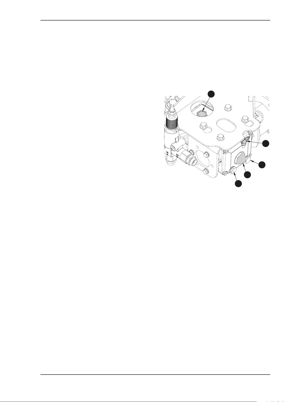
The oil level in the Supawash pump should be checked weekly. There is a sight level glass and
dipstick at the front end of the pump.
It is recommended that the oil is changed after the first 50 hours of operation and then changed at
every C Service.
Johnston Sweepers Limited
Oil Level / Changing
The water pump is mounted on the offside end
of the central crossmember near to the tip rams.
The pump oil level should be checked weekly
and is visible through window ‘A’ and a dipstick
‘B’ is provided with high and low level marks. The
oil is introduced via filler port ‘C’. The pump oil
is drained via either of plugs ‘D’. The oil colour
should be clear, if it is frothy/milky when seen
through window ‘A’, then water has entered the
oil and it should be changed immediately and
the cause investigated. The recommended oil is
shown in the lubrication chart.
RTOG. 045
C
B
D
A
D
Page Issue A
Chapter - Routine Maintenance
OG6:15
Page 52
RT655 Operator’s Guide
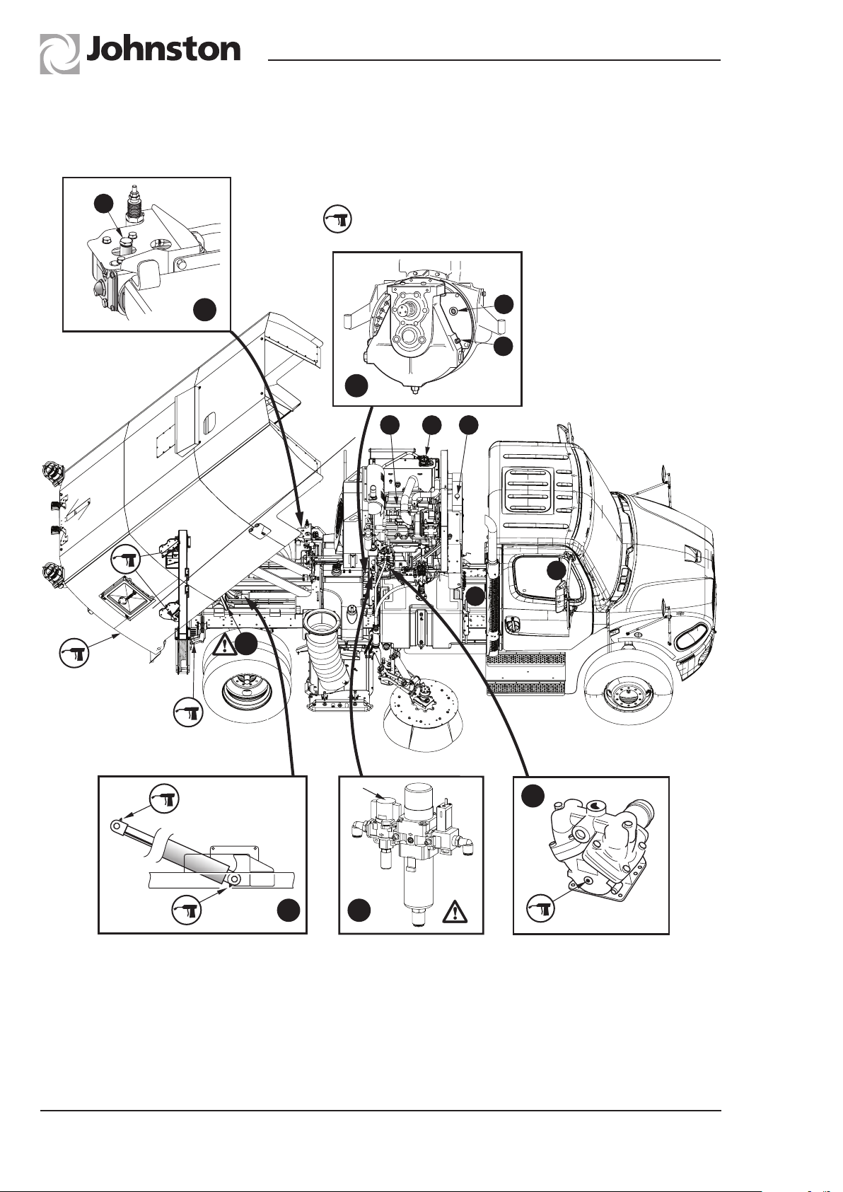
LUBRICATION DIAGRAM - RH SWEEP MACHINE SHOWN
LUBRICATIONDIAGRAM
Refer to MaintenanceSchedules
forlubrication intervals
H
GREASE
6
D
B
4
A
G
C
E
F
1
(i)
5
2
3
1 Body prop - Ensure autoprop has engaged when body is raised.
2 Filter regulator unit (FR) - (i) Isolation valve.
3 Water pump.
4 ‘Z’ drive gearbox.
5 Body tip cylinders.
6 Supawash pump - option.
OG6:16
Chapter - Routine Maintenance
RTOG. 054
Page Issue A
Page 53

RT655 Operator’s Guide
Johnston Sweepers Limited
RT655 Approved Lubricants
Capacity/
ISO Oil Grade
8.0L/
A Engine
ACEA E3 - E5
B Gearbox
H Supawash Pump
C Hydraulic System/
D Fluid Flywheel
E Chassis PAS
F Auto Gearbox
G Antifreeze 15L 39664 -
2.50L
0.37L - GL 4
80L
4.85L
- 94-67-1 -
Johnston
Part No.
94-23-5
63684-5 -
39677-5 -
Fuchs
Titan Cytrac
HSY 75W -90
Grease Nipple - 94-69 -
Battery Terminals -
The above oils are those approved by Johnston Sweepers.
Other manufacturer’s oils must be of equivalent grade.
PETROLEUM JELLY
Page Issue A
Chapter - Routine Maintenance
OG6:17
Page 54

RT655 Operator’s Guide
OG6:18
Chapter - Routine Maintenance
Page Issue A
Page 55

RT655 Operator’s Guide
Johnston Sweepers Limited
CHAPTER
7
Conformity Certificates
Table of Contents
Subject Page
EC Declaration of Conformity Certificates
Safety Requirements OG7 : 2
Noise - Engines OG7 : 3
Noise and Vibration
Levels OG7 : 4
Page Issue A
Chapter - Conformity Certificates
OG7:1
Page 56
RT655 Operator’s Guide
TMS RANGE ALL MODELS - (SAFETY) - ENGLISH
EC DECLARATION OF CONFORMITY
Manufacturer’s Name: Johnston Sweepers Limited
Manufacturer’s Address: Curtis Road, Dorking, Surrey,
England, RH4 1XF
Declares that:
Product Name: Johnston Road Surface Cleaner
Product Type(s): VT501, VT651, VT801
VS501, VS651, VS801
ES351, RT655
Product Options: All
Product Serial Number:
Conforms to the following standards:
E.C. Council Directive 2006/42/EC and amendments.
BS EN 13019 : 2008. Machines for Road Surface Cleaning
Safety Requirements
Clive Offley
Engineering Director
Johnston Sweepers Ltd.
20/07/2015
Truck Mounted Issue : 06
TMS Issue : 17 - GB
OG7:2
Chapter - Conformity Certificates
Page Issue A
Page 57
RT655 Operator’s Guide
RT655 - (NOISE) - ENGLISH
(NOISE EMISSION IN THE ENVIRONMENT BY EQUIPMENT
Manufacturer’s Name: Johnston Sweepers Limited
Manufacturer’s Address: Curtis Road, Dorking,
Surrey, RH4 1XF, England.
Technical Documentation Research and Development Department,
maintained by: Johnston Sweepers Limited,
Curtis Road, Dorking,
Surrey, RH4 1XF, England.
equipment conforms to the requirements of EC Directive 2000/14/EC:
Johnston Sweepers Limited
EC DECLARATION OF CONFORMITY
FOR USE OUTDOORS: DIRECTIVE 2000/14/EC)
Johnston Sweepers Ltd. hereby declares that the following
Description of Equipment:
EC Directive 2000/14/EC, Annex 1, Item 46:
Power sweeper
Product Name and Johnston RT655 chassis-mounted powered
Description: air regenerative sweeper, with HP turbo-
charged auxiliary engine pack.
Maximum Measured 107dB(A)
Sound Power Level (LWA):
Guaranteed Maximum 108dB(A)
Sound Power Level (L
WA
):
Conformity Assessment Internal control of production
Procedure:
(Ref: Annex V - 2000/14/EC)
Other EC Directives applied 98/37/EC and amendments
to this equipment:
Place and Date of this Johnston Sweepers Limited,
Declaration: Curtis Road, Dorking, Surrey, RH4 1XF
England.
January 2006
Signed by:
Clive Offley
Engineering Director
Johnston Sweepers Ltd
RT655 Issue: 01 - GB
Page Issue A
Chapter - Conformity Certificates
OG7:3
Page 58

RT655 Operator’s Guide
NOISE AND VIBRATION
Safety Notice
●Ear defenders are recommended when working around the machine
Noise Levels
All noise levels are given at maximum engine operating speeds, but in normal operation are likely
to be lower than the figures quoted.
In-cab noise levels with the windows closed 68 dB(A) nominal, dependent upon chassis.
External noise levels at one metre distance of the side of the machine, i.e. Wanderhose operation,
are 93 dB(A).
Noise levels at 3 metres in front of the machine (manual pavement sweeping into the gutter) are
83 dB(A).
For maximum sound power level see Noise Declaration Certificate.
Vibration
Vibration levels in accordance with 2002/42/EC as amended.
Hand-Arm
The vector sum weighted root mean square acceleration values (a
sweeping/ washing activities do not exceed 2.5 m/s2.
Whole Body
The dominant axis weighted root mean square acceleration values (aw) during recommended
sweeping/ washing activities do not exceed 0.5 m/s2.
Conditions of test - body empty and water tanks full on public thoroughfare.
The Control of Vibration at Work Regulations 2005 Directive 2002/44/EEC.
In accordance with the above Regulation the operators of the machine over a typical duty cycle will
be subjected to an 8 hour energy equivalent acceleration A(8) below the Exposure Action Level
(EAV) for both Hand-arm and Whole Body Vibration.
) during recommended
h.w
These Limits are:
Hand-arm: EAV 2.5m/s
Whole body: EAV 0.5m/s
OG7:4
Chapter - Conformity Certificates
2
2
Page Issue A
 Loading...