

Page 1
Actuators & Actuated Valves
User Manual
JV-E
Electric 1/4 Turn Johnson Valves Actuator
20Nm - 1200Nm
The JV-E electric actuator is designed for quarter turn applications on ball and butterfly valves with bases to ISO 5211
& DIN 3337 standard. Small, lightweight and compact in design but still offering high output torques.
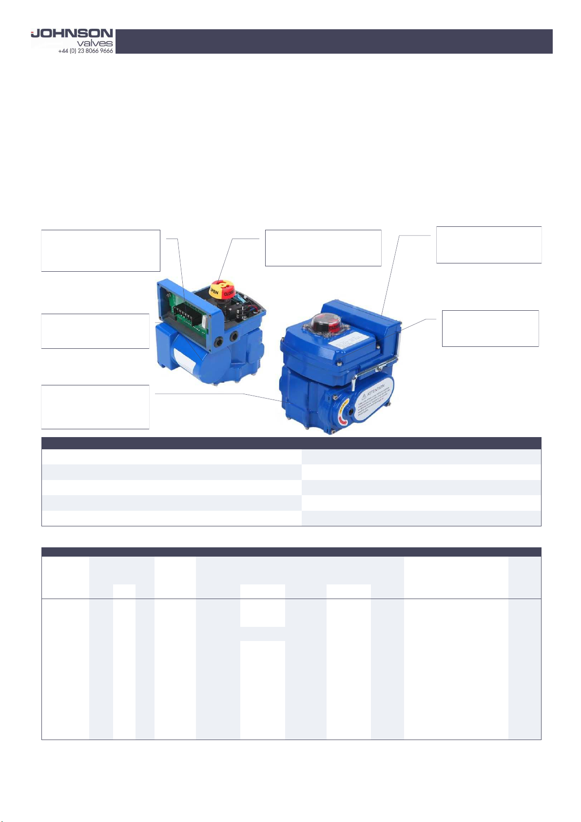
Simple Installation
All connections are located in a
separate terminal box, minimising
the amount of disassembly required.
Efficient Design
High torques are achieved with
relatively low power consump-
Self Locking
The risk of overheating due to
repeated operations is avoided
with this feature.
High Visibility Position Indicator
Making visual checks easy even
from a distance.
Watertight Unit
IP68 Watertight (IP68 5m 120hr)
Captive Bolts
Bolts will not be lost even
when the cover is open.
Standard Specifications
Enclosure IP68 Watertight (IP68 5m 120hr) Travel Angle 90o ± 5o
Power Supply 110V & 250V (1PH) / 24VDC / 380V & 440V (3PH) *** Casing Material Aluminium Alloy, Dry Power Polyester Coated
Indicator Dome Type Mechanical Terminal Block Push Button
Limit Switches 2 x Open / 2 x Close, SPDT, 250V AC * Ambient Temp -20 to +60oC
Inside Heater (AC Only) 1PH 110/220V AC ** Mechanism Scotch-Yoke (JV-E05 - Spur Gear Type)
* not available on JV-E02 ** not available on JV-E02, 04 & 05 ***Only available for JV-E16, 28, 40, 50, 80 & 120
ADDITIONAL DATA
Model Maximum Op. Time Rated Current (A) Motor Manual
No. Torque Output 50 / 60Hz AC (1PH) AC (3PH) DC Insulation / output Handle
0o 45o 90o 90o (sec.) 110V 220V 380V 440V 24V (AC . DC) Turns
JV-E02 20 20 20 17.5/14.5 0.29/0.25 0.12/0.1 N/A N/A 1.5 E . B/10W . 10W 3
JVE-04 40 40 40 12/10 0.67/0.6 0.23/0.2 N/A N/A 2 E . B/10W . 10W 3
JV-E05 50 50 50 13 N/A N/A 2 B . B/10W . 10W 18 (100-250V AC) 0.1-0.25
JV-E10 100 65 100 22/18 0.82/0.75 0.42/0.40 N/A N/A 2.5 F . B/10W . 15W 15
JV-E16 160 107 160 28/23 0.94/0.85 0.50/0.46 0.47/0.37 0.62/0.49 4 F . B/15W . 15W 19
JV-E28 280 190 280 40/33 0.94/0.85 0.50/0.46 0.47/0.37 0.62/0.49 4 F . B/15W . 15W 23
JV-E40 400 270 400 40/33 1.09/1.23 0.54/0.58 0.16/0.15 0.18/0.16 5.5 F . B/25W . 40W 23
JV-E50 500 350 500 40/33 1.55/1.75 0.72/0.90 0.30/0.28 0.40/0.30 N/A F/40W 23
JV-E80 800 540 800 51/42 1.97/2.83 1.09/1.46 0.50/0.54 0.57/0.55 N/A F/60W 77
JV-E120 1200 800 120 51/42 1.97/2.83 1.09/1.46 0.50/0.54 0.57/0.55 N/A F/90W 77
(s) spanner operated
Page 2

JV-E USER MANUAL
- Table of Content -
1. Summary ………………………………………………………………………………………………
1-1. Model System ………………………………………………………………………………………
1-2. Label ……………………………………………………………………………………………
2. Products
2-1. Construction ………………………………………………………………………………………
3. Installation
3-1. Attachable Valve ………………………………………………………………………………
3-2. Selection of Actuator …………………………………………………………………………
3-3. Caution during Installation ………………………………………………………………………
4. Operation
4-1. Operation ……………………………………………………………………………………………
4-2. Limit Switch Setting ……………………………………………………………………………
4-3. Caution during Operation ………………………………………………………………………
5. Maintenance & Repair
5-1. Self-Diagnosis ……………………………………………………………………………………
5-2. Assembling & Disassembling …………………………………………………………………
6. Customer Service Support Contact ……………………………………………………………
Revision
Date: 04/12/2015
Contents: Issued
Issued: Lee Houghton
1. Summary
JV-E Actuator allows to conveniently open & close the Valve fast in any places wherever the electricity are
connected & available. The Valve is designed to thoroughly assure the safety & convenience of users, however,
please make sure to operate after reading & digesting the User Manual completely. Please check the homepage of
Johnson Valves or inquire with Johnson Valves & authorized Agents for those items & subjects not described in the
Manual.
- Data contained in the User Manual may be subject to change without advance notice
for improvement of performance & safety of Product.
※ Did you receive the JV-E ELECTRIC ACTUATOR?
Followings must be checked before operation.
1) It should be checked if the label is well attached, and if the specification of the label is the same with your order.
2) It should be checked if the connection diagram is attached at the inside of terminal cover.
3) It should be checked if the manual lever is attached at side or lower part.
4) It should be checked if there is any other scratch or dent.
Page 3
1-1. Model System
Model number: Voltage:
Serial Number: Rated current:
Max torque: Nm Power:
Op time (90): secs
Output flange: Options:
This is the JV-E series user manual and each model is as follows.
JV-E05
JV-E = Johnson Valves Electric / 05 = Size & torque output
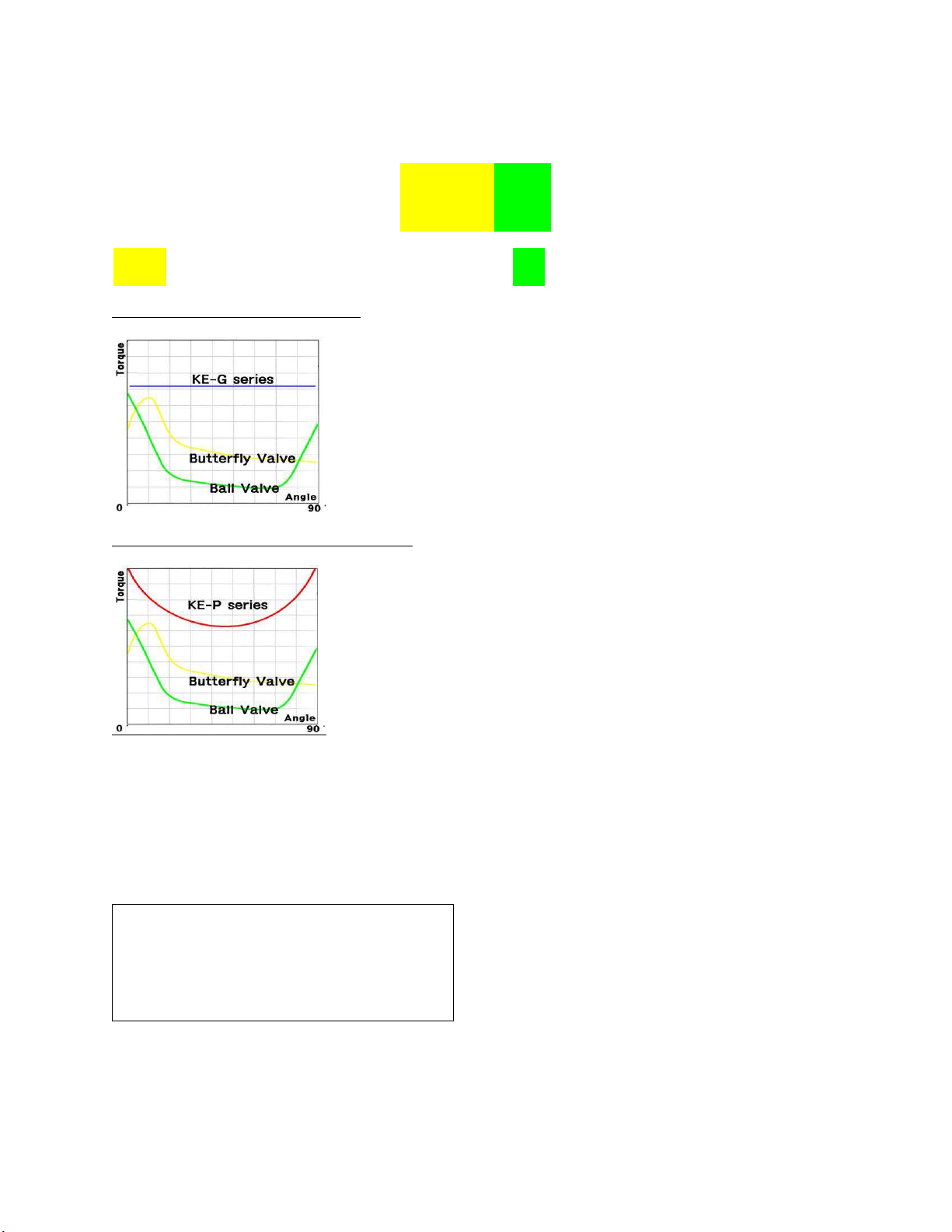
JV-E05 series (Spur gear) Torque graph
JV-E10 to 50 series (Scotch yoke) Torque graph
Temperature range = -20 to +60℃
1-2. Label
Models can be identified as labels with lot numbers and model numbers are attached to the products of Johnson
valves as follows.
Page 4
2. Products
2-1. Construction
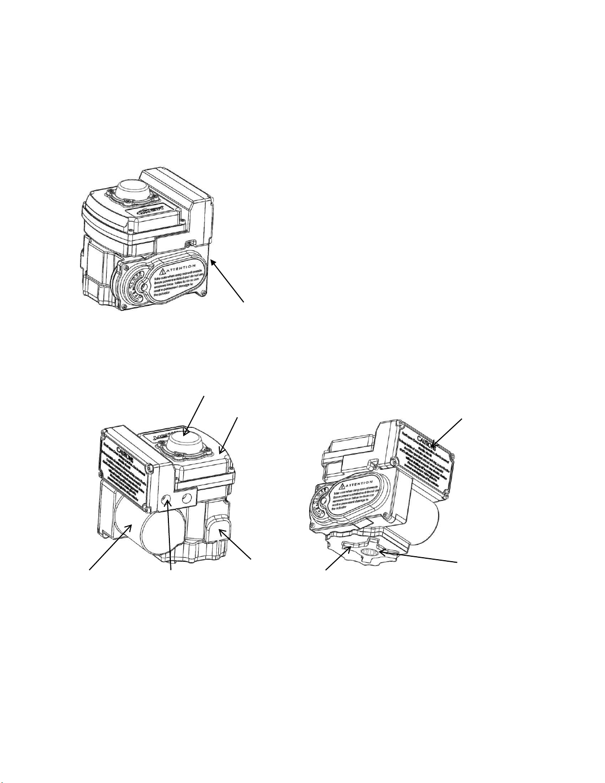
Construction of the Product is illustrated as following.
Appearance based on JV-E16
Window
Cover Terminal block
Body Shaft
Motor Cable entries ISO pad
Names of each parts based on JV-E16
Page 5

3. Installation
User should execute the product installation after thoroughly digesting the following content.
3-1. Attachable Valve
The JV-E product can be applied to all the Rotary Type Valve executing opening & closing actions rotating 90˚.
a. Major Components ; Ball Valve (2 way, 3 way), Butterfly Valve
3-2. Selection of Actuator
Check the following items in advance when selecting the model of Actuator.
a. Required torque to open & close the Valve
b. Voltage and Operation Environment of Site (High Temperature/Low Temperature)
c. Fluid Characteristic
d. Other items to consider to operate the Actuator
3-3. Caution during Installation
a. When installing the Product, execute the installation after either removing the potentially hazardous elements or
mounting the safety devices considering the accidents & danger that may be happen during the installation works.
b. Johnson Valves Product can be used in any indoor & outdoor places except with the explosive environments,
while the rust may be processed a little fast in case of installation in sea shore locations.
c. CAUTION as for the Products weighing over 20Kg, the Label of below shown flowing may be attached, either
lifting by two persons or utilizing the appropriate device to move the product.
d. WARNING during the operation, electric current should not be sent to this product before it is completely
equipped to a valve.
e. When attaching the Accessories, install after checking the Jointing Method & Joint Section.
f. As a basic installation direction, the window should be faced upward, but in case of vertical piping, it must be
installed with the cable entries faced downward, and after connection please seal the cable entries in order to prevent
any foreign materials from entering through it.
g. Do never either use the hazardous substances or operate or store under the condition using hazardous substances.
Definition of hazardous substances are those potentially harmful materials, e.g. which may cause explosion or fire,
flammable materials, toxic materials, corrosive materials & etc
h. Please make sure to connect a line at a correct location after checking the connection diagram attached on the
terminal block cover. Wrong connection may cause not only the failure of product, but also an accident.
Page 6
4. Operation
User of Product should operate upon fully recognizing the potential danger caused by the inappropriate
management.
4-1. Operation
▷ Operation Voltage: Product is delivered with a voltage selected as per the demand of a user. Please use the
product after checking if the voltage of the site and the one in the product label are same before installation.
4-2. Limit Switch Setting
Our product is delivered with the limit switch adjusted basically as 90 degrees. However, please follow the below
guides if the opening/closing angles are not correct when the product is operated, or if the limit switch should be set
again according to the demand of the site.
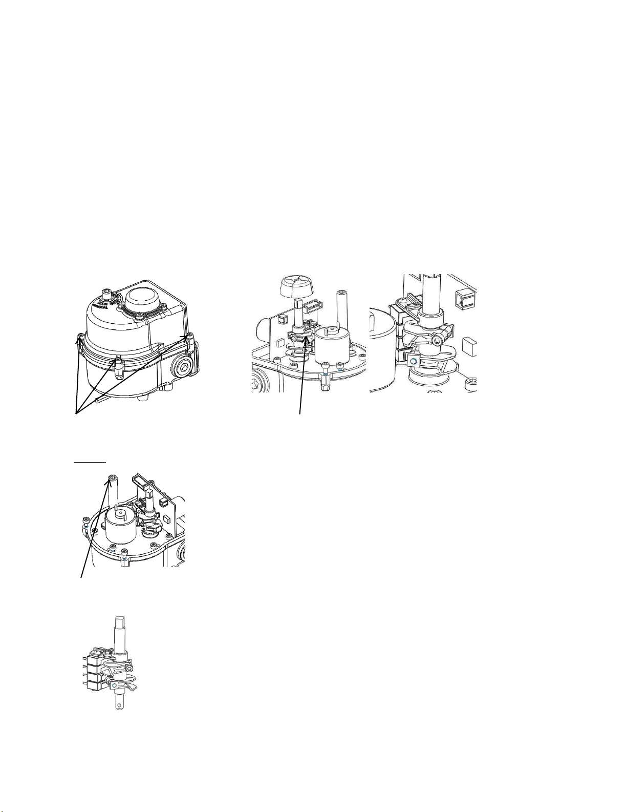
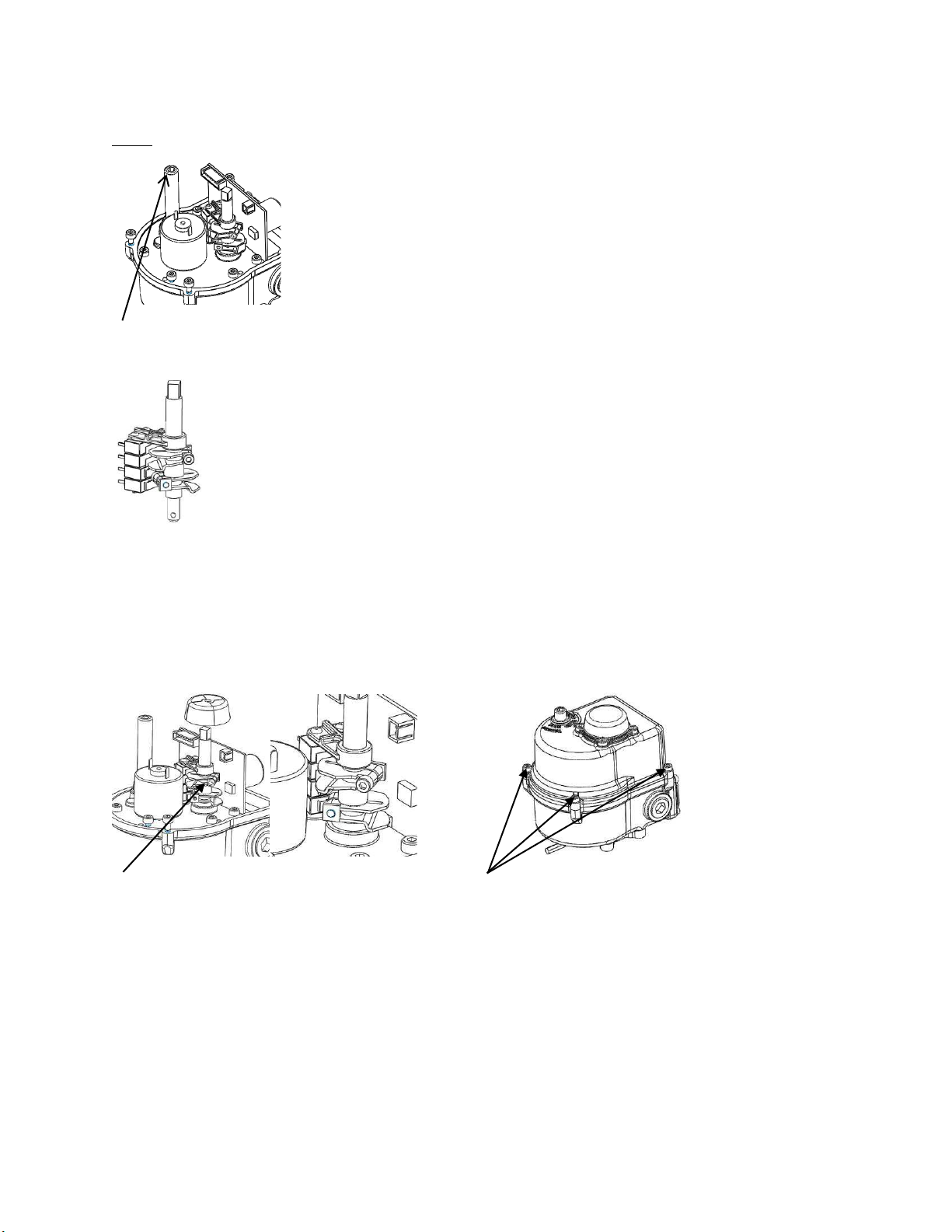
Limit Switch Setting – JV-E05
Please open the cover by The indicator should be separated and
loosening the 4 bolts detached upward, and the cam fixing bolt
should be loosened with a hexagon key
CLOSE
The angle required by the user should be set by turning the wrench to the direction of CLOSE (CW) in a state
that it is stuck to the manual area and fully pressed. The wrench is attached to the product.
※ Refer to cautions
Rotate the upper cam out of the two cams for the 2 limit switches to be all pressed slightly while making a click
sound.
Page 7
OPEN
The angle required by the user should be set by turning the wrench to the direction of OPEN (CCW) in a state
that it is stuck to the manual area and fully pressed. The wrench is attached to the product.
※ Refer to cautions
Rotate the lower cam out of the two cams for the 2 limit switches to be all pressed slightly while making a click
sound.
※ Cautions ※ In case of JV-E05 series, the manual shaft must be rotated in a state that it is fully pressed by use of the
wrench equipped to the product. Even though rotated in a state it is not fully pressed, it can be opened and closed, but
it is much difficult as the connected motor is rotated together, and the different sound of motor rotation [wing] is
heard.
The cap fixing bolt should be fastened with The cover must be closed and the indicator
a wrench, and the indicator should be angled bolt should be fastened after checking if the
and stuck to the shaft. OPEN/CLOSE is correct.
※Cautions※ In case the indicator of is wrongly
stuck, the OPEN/CLOSE may be reversed when
the cover is closed. The bolt must be fastened after
closing the cover, and after checking if the
OPEN/CLOSE of the indicator is same with the
state of the product and the valve.
Page 8
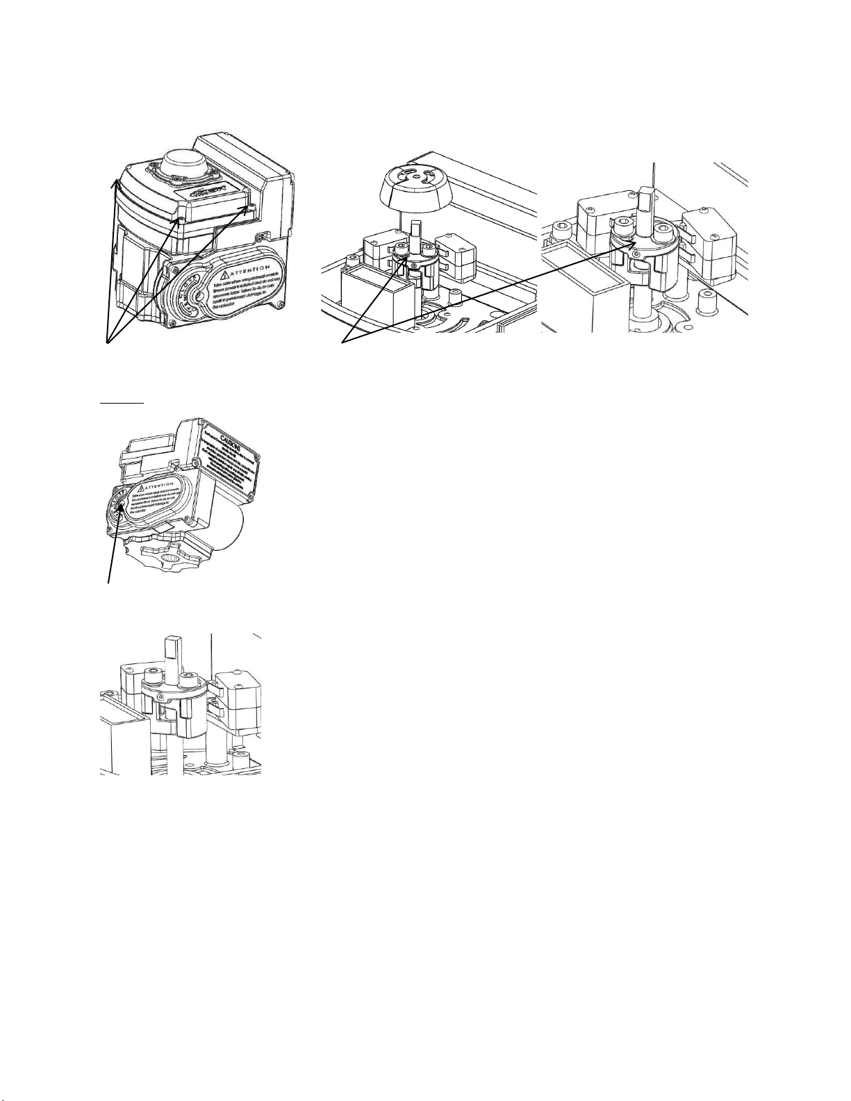
Limit Switch Setting – JV-E10 to 50
Please open the cover by The indicator should be separated and detached upward, and
loosening the 4 bolts. the cam fixing bolt should be loosened with a hex key.
CLOSE
The angle required by the user should be set by turning the wrench to the direction of CLOSE (CW) in a state
that it is stuck to the manual area. The wrench is attached to the product.
Rotate the Upper Cam out of the two cams for the 2 CLOSE limit switches to be all pressed slightly while
making a click sound.
※Refer to below cautions
Page 9
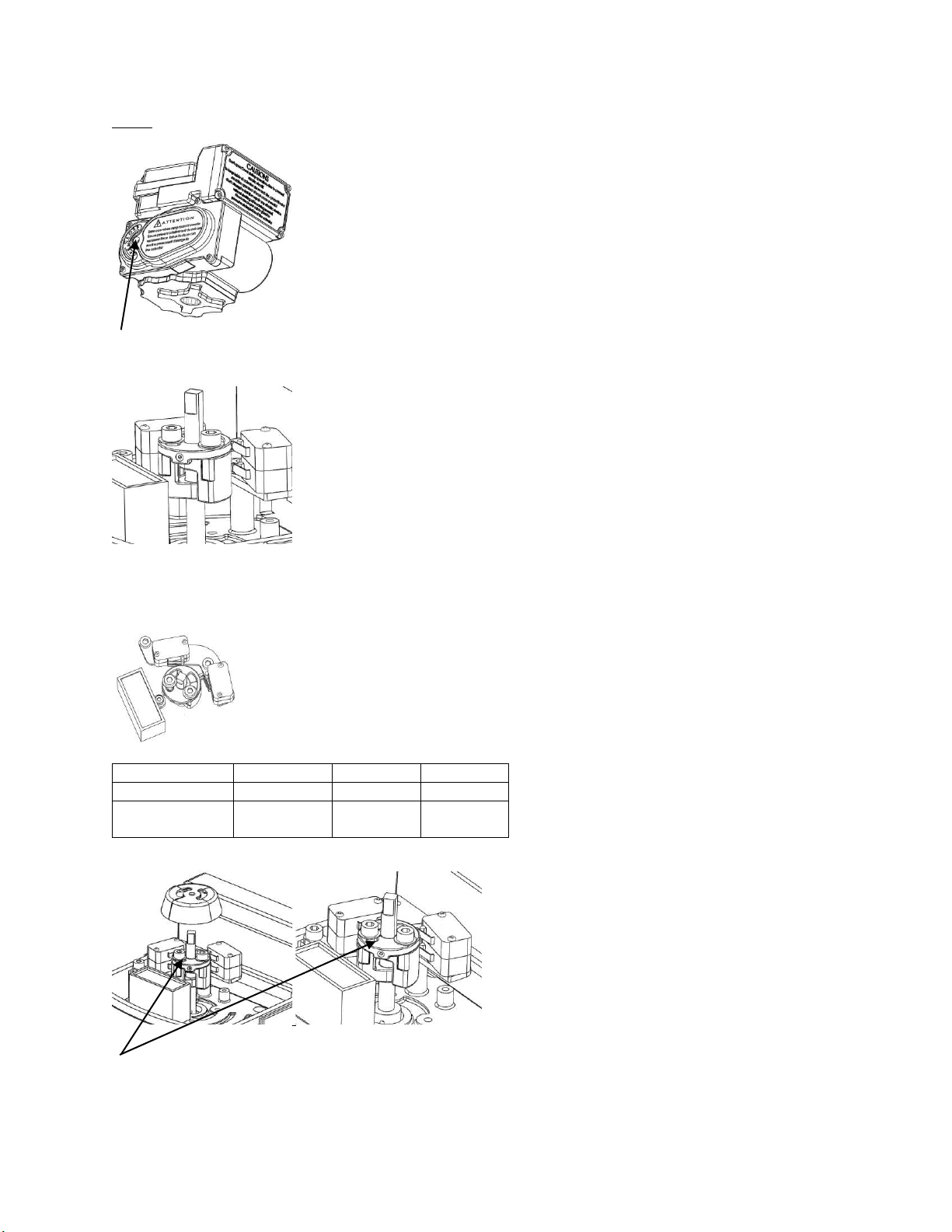
OPEN
Model
A B C
JV-E10
Condenser
OPEN
CLOSE
JV-E16
JV-E50
Condenser
CLOSE
OPEN
The angle required by the user should be set by turning the wrench to the direction of OPEN (CW) in a state that
it is stuck to the manual area. The wrench is attached to the product.
Rotate the lower cam out of the two cams for the 2 CLOSE limit switches to be all pressed slightly while
making a click sound.
※Refer to below cautions
※Cautions※
The cap fixing bolt (circled area) should be fastened with a wrench, and the indicator should be angled and stuck
to the shaft.
Page 10
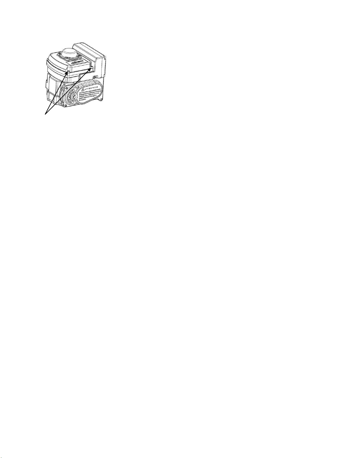
The cover should be closed, and the indicator bolt should be fastened after checking if the OPEN/CLOSE is
correct.
※Cautions※ In case the indicator of is wrongly stuck, the OPEN/CLOSE may be reversed when the cover is closed. The
bolt must be fastened after closing the cover, and after checking if the OPEN/CLOSE of the indicator is same with the state of the
product and the valve.
4-3. Caution during Operation
a. Johnson Valves Product is designed to open & closed the Valve. Do not use the Product on the purposes other
than specified applications.
b. Ensure not to have the unskilled labors user the Product at own discretion.
c. Ensure to approach after completely securing the safety when the access to the Product under operation is desired.
d. It should be kept at a cool and dry place in case not used for a long period and it is recommended that the power
should be provided about 1 time and that the product should be operated more than 5 times for a month.
Page 11
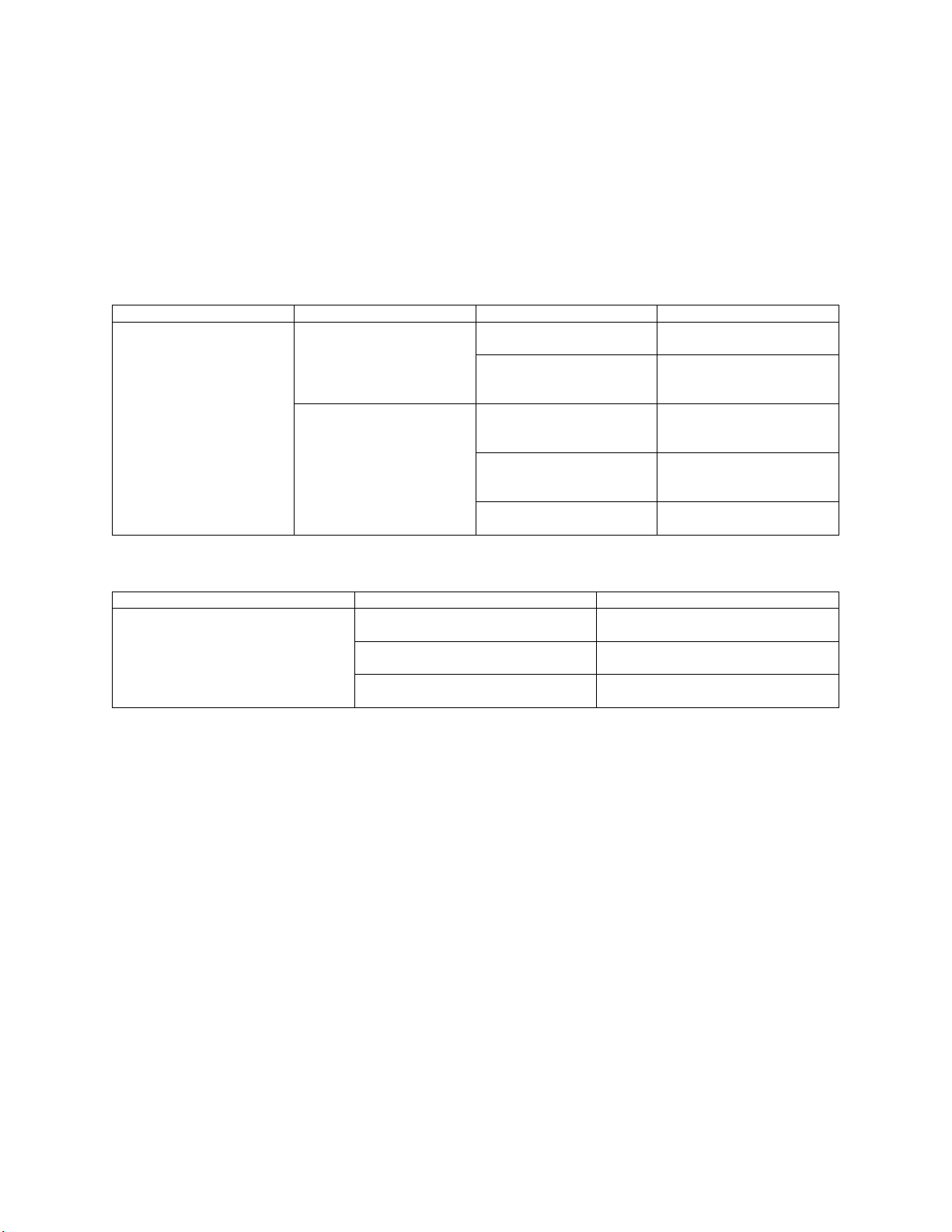
5. Maintenance & Repair
Check
Result
Cause
Measures
Turn on the power after de-
taching the actuator from the
valve
Operated
Valve torque is higher than
the actuator
The actuator of the higher
model should be equipped
Voltage of the site is to low
The equipment is
reinforced for the product to
receive the correct voltage
Not operated
The power of the product
and the site is not
corresponded
Exchange it with a product
that meets the voltage of the
site
The connection is wrongly
made
The connection should be
made again referring to the
correct wiring diagram
The limit switch is wrongly
set
The limit switch is set again
referring to the user manual
Check Area
Cause
Measures
Actuator check
The limit switch is wrongly set
The valve torque is higher than that of
the actuator
Valve torque is higher than the actuator
The actuator higher model should be
equipped
The motor TP (Thermo Protect) is cut
It should be operated again after a fixed
time has passed
5-1. Self Diagnosis
All the Johnson Valves Actuators, going through the high pressure test from the development stage, are to be individually & fully tested prior to the shipment from factory. However, in the event the Product oftentimes does not
operate with normal condition, execute the Self Diagnosis referring the below table. Nevertheless, if the trouble occurred is not still resolved, contact the Johnson Valves or authorized Agents for customer service support.
▷ Valve Not Working At All
▷ When Valve is Closed Stopping the Opening Process
※Caution ※ In case there is any burnt smell, or any spark is arisen, immediately shut off the power, and call to
head office or agents after separating the product safely.
Page 12

5-2. Assembling & Disassembling
The assembling & disassembling of Product should be executed by the Skilled Labors of Johnson Valves or an
authorized Agents to secure the safety of Users and life cycle of Product in principle. However, in the event the
indispensable assembling & disassembling of Product at site is desired due to unavoidable reasons, make sure to
execute the works only after consulting with the persons in charge of Product of Johnson Valves or authorized
Agents to receive sufficient instructions through e-mail or telephone communications.
▷ Skilled Labor; Persons who have received the professional trainings of Johnson Valves or authorized Agents and
recognizes all the potentially dangerous situations. Further, the Skilled Labor must possess all the required
knowledge on app applicable laws & regulations with regard to the occurrence of unexpected accidents and other
special job site conditions.
※ In the event the addition or variation from the original design of Product are to be desired, make sure to execute
the works after consulting with Johnson Valves or authorized Agents to receive sufficient instructions. Johnson
valves does not assume the responsibility for any property damages or personal injuries caused by the User's
operating faults or arbitrary design change & improper maintenance works.
6. Customer Service Support Contact
Johnson Valves Head Office Address:
Unit 7 Trinity Court, Calmore Industrial Estate, Totton, Southampton, SO40 3WX
Head Office Telephone: +44 (0) 2380 669 666
KOSA+ Head Office Fax: +44 (0) 2380 669 606
Head Office e-mail:
The User Manual is made to allow the operation & convenience of Purchaser, User & Skilled
Labor of Product, and Johnson Valves duly reserves the right of operating instruction & guides
contained in the Manual. As such, any sorts of revisions & sales by copying of entire or part
of the Manual without securing the written consent of Johnson Valves in advance should be absolutely
prohibited.
 Loading...