

Johnson & Starley WARMCAIR C20DW, WARMCAIR C16DW, WARMCAIR C10DW Installation, Commissioning & Servicing Instructions

www.johnsonandstarley.co.uk
INSTALLATION, COMMISSIONING
& SERVICING INSTRUCTIONS
WARMCAIR C20DW
Condensing Air & Water Heater
High Efciency Downow
Condensing Air & Water Heater
WarmCair C20DW - G.C. No. 43-417-61
These instructions are to be left with the User
Publication No. ZZ 1448-4
December 2016

www.johnsonandstarley.co.uk
2
CONTENTS
The Benchmark Scheme 2
1 Features 3
2 General Description 3
3 Building Standards & Regulations 4
4 Safety, Electrical & Gas Information 4
General Safety Information
Power Flushing
Electrical Connections
Handling the unit
Operating the Appliance
Gas Supply
Water Supply
5 Technical Data 6
Technical Data
Performance Data
6 Heater Positioning 7
7 Heater Compartment Clearances 7
8 Duct System 7
Return Air
9 Heating System 8
Warm Delivered Air System
Additional Radiator System If Fitted
Schematics
Pipework Sizing
Water Treatment
Hot Water System For DHW
10 Flue Instructions 10
Types of Flue Systems
Flue Terminal Positions
Flue Requirements & General Information
Extended Horizontal Flue Configuration Examples
Vertical Flue Configuration Example
Optional Roof Outlets
Plume Terminal Outlets
Conventional 60/100mm Flue Accessories Part No.s
11 Condensate Pump & Drain Tube 15
Condensate Pump
Condensate Tube Routing Options
12 Electrical 16
13 Warm Air Fan Performance 16
14 Operating Modes 16
15 Domestic Hot Water Heating Commissioning 17
Check Gas Installation
Check the Operational Gas Inlet Pressure
Air Purge Function
Reset Procedure
16 Initial Lighting 18
Warm Air Central Heating
Water Circulation System
Balance the System
Central Heating Water Temperatures
17 Warm Air Heating Commissioning 19
With Thermista-stat Fitted
With No Thermista-stat Fitted
18 Handing Over 19
19 Servicing & Maintenance 20
Service Schedule
Initial Inspection
Servicing Sequence
Flue Inspection & Checks
Gaining Access to the Appliance
Air Filter Removal
Upper Panel Removal
Control Panel
Combustion Air Fan
Burner Assembly
Water Heat Exchanger
Servicing the Warm Air Heating
Gaining Access for Servicing the Heat Generator
Lower Panel Removal
Air Circulation Fan
Air to Water Heat Exchanger
Condensate Pump
Condensate Trap
20 Parts Replacements 24
Part Replacements without Draining the System
Control Panel
Burner Injector
Combustion Air Fan
Burner Assembly
Flow & Return Thermistor Sensors
Ignition/Detection Electrode
Gas Valve
Warm Air PCB
PCB Interface
Air Circulation Fan
Condensate Pump
Condensate Trap
Diverter Acuator Head
Parts Replacement By Draining the System
Draining the Appliance
Pump Head
Diverter Cartridge
Automatic Air Vent
Air To Water Heat Exchanger
21 Fault Finding 28
22 Wiring Diagram 34
23 Dimensions 35
24 Exploded Spares Diagram 36
25 List of Spares 38
26 List of Ancillaries 39
27 Benchmark Checklist and Service Record 41
Code of Practice
Commissioning Checklist
Service Record
In the interest of continuous development Johnson and Starley reserve the right to change specication without prior notice.
Johnson and Starley prides itself on it’s ability to supply spare parts quickly and efciently.
PLEASE READ THESE INSTRUCTIONS CAREFULLY BEFORE STARTING INSTALLATION.
LEAVE THESE INSTRUCTION WITH THE USER OR AT THE GAS METER AFTER INSTALLATION
The Benchmark Scheme
Benchmark places responsibilities on both manufacturers and installers. The purpose is to ensure that
customers are provided with the correct equipment for their needs, that it is installed, commissioned and
serviced in accordance with the manufacturer’s instructions by competent persons and that it meets the
requirements of the appropriate Building Regulations. The Benchmark Checklist can be used to demonstrate
compliance with Building Regulations and should be provided to the customer for future reference.
Visit www.centralheating.co.uk for more information.
Installers are required to carry out installation, commissioning and servicing work in accordance with the Benchmark Code of Practice which is available
from the Heating and Hot water Industry Council who manage and promote the Scheme.

3
Sales/Spares & Replacement Help Line 01604 762881
1. FEATURES
Appliance Classification:
The WarmCair C20DW has been tested
and CE certified by B.S.I Ltd for use with
NATURAL gas G20.
FEATURES
1. Flue Adapter
(shown fitted but not supplied)
2. Flue Test Point
3. Inspection Glass
4. Ignition Detection Electrode
5. Burner Injector
6. Flow & Return Sensors
7. Pressure Differential Tube
8. Gas Valve
9. Air Filter
10. Condensate Trap
11. Gas Cock
12. Circulation Fan
13. Pump/Diverter Assembly
14. Return Water Temperature Sensor
15. Heat Exchanger
(Warm Air)
16. Drain Cock
17. Access Panel
18. Condensate Pump
19. Condensate Pipe
20. Condensate Drain Tube
21. Electronic Air Filter & LED
22 PCB Interface
23. Combustion Fan
24. Warm Air PCB
25. Heat Generator
(water)
26. Flue Sensor
2. BRIEF DESCRIPTION
2.1 The WarmCair C20DW is a highly efficient combined condensing gas fired water to air downflow forced
convection air heater and water heater. Significant reductions in Carbon and NOx emissions are achieved.
This appliance has been designed with two compartments, one to provide the user with Warm Air Central
Heating and one to provide Domestic Hot Water. Using sophisticated controls and enabling it to provide a warm
air heat output of 16.0kW and hot water output of 24.2 fully modulating down to 4.8kW. It is room sealed, with a
stainless steel heat exchanger, using a vertical or horizontal Concentric Flue System.
The WarmCair C20DW combinds air heater is ideally suited for new built dwellings and the replacement of
existing non-condensing air heaters. For Indirect system applications only.
2.2 “Summer Air Circulation” of unheated air is available by manual selection (see the user’s instructions)
2.3 The air is drawn in through the air filter or air cleaner (if fitted) and the heat exchanger by a centrifugal fan, and is
discharged through the base of the unit. A Summer Air Circulation switch (optional) provides the facility to supply unheated
air to the air outlets during warm weather. Modairflow control is incorporated for modulating of the air circulation fan.
9
14
1
2
3
4
8
7
11
10
13
23
21
24
25
26
6
15
16
17
19
20
18
22
5
12
FIGURE 1. CONTROL PANEL

www.johnsonandstarley.co.uk
4
3. BUILDING STANDARDS & REGULATIONS
STATUTE LAW DEFINES THAT ALL GAS APPLIANCES MUST BE INSTALLED BY
COMPETENT PERSONS, i.e. GAS SAFE REGISTERED INSTALLERS.
GAS SAFE MEMBERSHIP ENQUIRIES TEL: 0800 408 5500 IN ACCORDANCE WITH
THE GAS SAFETY (INSTALLATION AND USE) REGULATIONS (CURRENT EDITION).
FAILURE TO COMPLY WITH THESE REGULATIONS MAY LEAD TO PROSECUTION.
3.1 INSTALLATION REGULATIONS
• Building Standards (Scotland) (Consolidation) Regulations
• Building Regulations Part L
• Gas Safety (Installation and Use) Regulations (as amended)
• The Water Fittings Regulations or Water bylaws in Scotland
• Model and Local Authority Byelaws
• Health & Safety Document No. 635.
• The Electricity at Work Regulations, 1989.
• Institute of Electrical Engineers (I.E.E) Wiring Regulations
• EU Regulation No 811/2013 and No. 812/2013 supplement Directive 2013/20/EU
This appliance has been Tested and Certified in order to meet the necessary European Directives and
comply with the latest Building Regulations.
• Efciency of Hot Water Boilers Directive 92/42/EEC
• Gas Appliance Directive 2009/142/EC
• Low Voltage Directive 2006/95/EEC
• Electromagnetic Compatibility Directive 2004/108EC
3.2 BUILDING STANDARDS AND REGULATIONS
Where no specific instructions are given, reference should be made to the relevant British Standard Code of Practice.
BS 5440:1 Flues (for gas appliances of rated input not exceeding 70 kW).
BS 5440:2 Ventilation (for gas appliances of rated input not exceeding 70 kW).
BS EN 12828 Heating Systems in buildings: Design for water based heating systems.
BS EN 12831 Heating Systems in buildings: Method for calculation of the design heat load.
BS EN 14336
Heating Systems in buildings: Installation and commissioning of water based heating systems.
BS 5546 Installation of gas hot water supplies for domestic purposes (2nd Family Gases)
BS 6798 Installation of gas fired hot water boilers of rated input not exceeding 70 kW.
BS 6891 Installation of Low Pressure Gas Pipework of up to 28mm (R1) in domestic premises
(2nd family gases).
BS 7671 Institute of Electrical Engineers (I.E.E) Wiring Regulations
IMPORTANT: This appliance is CE certificated for safety and performance. It is important that no modifications are
made to this appliance, unless fully approved in writing by Johnson & Starley Ltd. If in doubt please Ring Johnson &
Starley Ltd on Telephone 01604 762881.
4. SAFETY, ELECTRICAL, GAS & WATER INFORMATION
PLEASE READ THESE INSTRUCTIONS CAREFULLY BEFORE COMMENCING WITH THE INSTALLATION
4.1 GENERAL SAFETY INFORMATION
4.1.1 Only use WarmCair original spare parts on this appliance. Failure to do so will invalidate the guarantee.
4.1.2 The manufacturers instructions supplied must not be taken as overriding any statutory requirements.
4.1.3 No artificially softened water must not be used to fill the central heating system.
4.2 POWER FLUSHING - When a radiator system is also connected.
4.2.1 The system can be damaged by debris entering the heat exchanger and reduce efficiency. It is
recommended that the appliance is flushed, follow these guidelines as this will protect the unit and prolong
its life.
4.2.2
It is important that the system is flushed thoroughly before the appliance is left to operate (as recommended
in BS 7593) in order to maintain an efficiently operating heating system. For replacement installations, the
system MUST be flushed with the old unit in situ, in order to prevent the appliance becoming a trap for
system debris. Once the system has been flushed, an inhibitor (suitable for stainless steel heat exchangers)
should be added. Appropriate inhibitors are available, for example Sentinel, Fernox and Salamader. We also
recommend a Magnetic & Non Magnetic Filtration system is fitted between the last radiator and the boiler.
4.2.2 Failure to carry out the above procedure will invalidate the guarantee!

5
Sales/Spares & Replacement Help Line 01604 762881
4.3 ELECTRICAL INFORMATION
4.3.1 Ensure the mains supply voltage, frequency, number of phases and power rating comply with details on the
rating label.
4.3.2 All wiring must be in accordance with the appropriate standards. The equipment must be supplied with a
double pole isolator switch.
4.4 HANDLING THE UNIT
4.4.1 Ensure safety regulations and practices are adhered to when installing and using this equipment
4.4.2 The weight of this appliance exceeds that recommended for a one-man lift. It will therefore be necessary to
gain assistance at times during the installation procedure.
4.4.3 It should be noted that this appliance may contain sharp edges. Care MUST be taken when handling the
appliance to prevent injury.
4.4.4 Once the appliance has been fired beware that certain parts will be hot to the touch.
4.4.5 Do not install flues during rain, high winds or in severe weather conditions.
4.5 GAS SUPPLY
4.5.1 It is the responsibility of the Gas Installer to size the gas installation pipework in accordance with BS 6891.
Whilst the principle of the 1:1 gas valve ensures the WarmCair Combined DHW range is able to deliver
it’s full output at inlet pressures as low as 14mb, other gas appliances in the property may not be as tolerant. When operating pressures are found to be below the minimum meter outlet of 19mb these should be
checked to ensure this is adequate for correct and safe operation.
4.5.2 Allowing for the acceptable pressure loss of 1mb across the installation pipework, it can be assumed that
a minimum permitted operating pressure of 18mb will be delivered to the inlet of the appliance. (Reference
BS 6400-1 Clause 6.2 Pressure Absorption).
4.5.3 The external gas cock could further reduce the operating pressure when measured at its test point. The
pressure drop is relative to the heat input to the boiler (kW), refer to graph below.
IMPORTANT: Installation pipes must be fitted in accordance with BS 6891. In IE refer to IS.813.
4.6 WATER SUPPLY
4.6.1 Water connections to the unit should be by 22mm compression fittings that are suitable for the duty.
NOTE: UNDER NO CIRCUMSTANCES SHOULD ISOLATION VALVES BE FITTED.
IMPORTANT: It is recommended that the water system be drained and flushed prior to the installation of the
unit. A strainer should be fitted upstream of the unit. See Paragraph 4.2.
FIGURE 2. GAS COCK PRESSURE DROP
3
2.5
2
1.5
1
0.5
0
PRESSURE DROP (mbar)
0.0 0.5 10.0 15.0 20.0 25.0 30.0 35.0 40.0 45.0
HEAT INPUT TO BOILER (kW)
GAS LEAKS
DO NOT OPERATE ANY ELECTRICAL SWITCHES, OR USE A NAKED FLAME
TURN OFF THE GAS SUPPLY. VENTILATE THE AREA BY OPENING DOORS AND
WINDOWS. CALL THE NATIONAL GAS EMERGENCY SERVICE ON
0800 111999

www.johnsonandstarley.co.uk
6
Note: Gas consumption is calculated using a calorific value of 38.7 MJ/m³ gross or 34.9 MJ/m³ nett. To obtain the gas
consumption at a different calorific value:
a. For l/s - divide the gross heat input (kW) by the gross C.V. of the gas (MJ/m³)
b. For ft³/h - divide the gross heat input (Btu/h) by the gross C.V. of the gas (Btu/ft³)
c. For m³/h - multiply l/s by 3.6
TABLE 2. C20DW
PERFORMANCE DATA
MAXIMUM MINIMUM
Burner CO² (%)
case off
9.4 8.5
case on
9.6 8.7
± 0.5
PERFORMANCE DATA FOR WATER HEATING
Input Q
Net
kW 24 4.7
Gross
kW 26.6 5.21
Gas Consumption
m³/h 2.48 0.48
Output
Non condensing kW 23.4
Condensing
kW 25.6 5.17
NOx Classication
CLASS 5 34mg/kWh
Recommended Central Heating set point
20 - 82°C
5. TECHNICAL DATA
TABLE 1 C20DW
Maximum weight lift kg 82.5
Gas supply mbar 2H - G20 - 20mbar
Gas connection mm 15mm copper
Gas Injector size mm 4.75mm
Heating flow and return mm 22mm copper
Flue terminal diameter mm 100mm (4”)
Condense drain mm 6mm ID
Electrical supply V ~ Hz 230V ~ 50Hz
Electrical rating W 530
External fuse rating A 3
WARM AIR HEATING
Nominal Rated Output kW 20
Air on Temperature ˚C 20
Air off Temperature ˚C 67
Water Supply Temperature ˚C 80
Water Return Temperature ˚C 71
Water Flow Rate l/s 0.6
Air Volume m³/h 1224

7
Sales/Spares & Replacement Help Line 01604 762881
6. HEATER POSITIONING
6.1 This heater is not suitable for external installation unless it is protected from the elements by a suitable enclosure.
The enclosure must provide the clearance for installation, servicing and maintenance as well as the correct level of
ventilation. The selected position should allow for a suitable flue system to be installed.
6.2 When installed in a timber frame building guidance should be taken from the Gas Industry Publication IGE/UP-7 (Guide
for Gas Installations in Timber Frame Housing).
6.3 BS 6798 gives details of the essential features for a compartment or cupboard where a gas appliance is to be installed.
An existing cupboard may require modification.
IMPORTANT: This system can only be used in conjunction with an indirect system application.
6.4 If the heater is installed in a room containing a bath or shower it is important to locate the electrical switch in a position
where it cannot be touched by anyone using the bath or shower. The current IEE Wiring Regulations (BS 7671) for
England and electrical provision of the Building Regulations for Scotland gives details.
6.5 Room ventilation for the heater is not necessary as the heater draws its combustion air from the outside of the building,
cupboard or compartment ventilation is not necessary providing that the minimum clearances are maintained. However,
reference should be made to BS 5440 Pt. 2.
IMPORTANT: This appliance must be completely level. It MUST NOT lean in any direction. This will cause problems with
the condense draining.
7. HEATER COMPARTMENT CLEARANCES
7.1 IMPORTANT - If the heater is to be fitted to an existing base duct (warm air plenum), always ensure that installation is
carried out such that the rear of the heater is aligned with the rear of the base duct, so that any overhang or blanking off
will be at the front. In any event, blanking plates must be mechanically secured and all joints sealed.
7.2 When the heater is fitted into a compartment, a minimum clearance from the compartment walls of 3mm (
1
/8”) at the
sides, rear and front must be left. Where clearances are less than 75mm, internal surface must be lined with noncombustible material and the compartment must be of a fixed rigid structure. However, there is no requirement for the
use of non-combustible material at the front of the unit. Consideration should also be given to the space required for the
removal and replacement of the filter tray and the entry of the gas and electrical supplies. If gas connections are made
from a side entry, a minimum clearance of 75mm (3”) is required at that side.
7.3 For service access, a minimum clearance of 500mm (20”) is required at the front of the heater. Space must also be
allowed, in a compartment installation, to permit the complete removal of the heater.
7.4 In airing cupboard installations, the part used as the air heater compartment must comply with the relevant section of
BS 5864 and must be completely separated by either a non-combustible partition or a perforated metal partition with the
perforations not exceeding 13mm (½”). The secondary flue must be a tight fit where it passes through the partition and
must be suitably protected (see BS 5440: Part 1).
7.5 In under-stairs installations, the compartment must comply with the relevant section of BS 5864, provided that in addition
all internal surfaces (including the base) are non-combustible or lined with non-combustible material. This requirement
is applicable only to dwellings of more than two storeys.
7.6 In free-standing installations, (see instructions packed with top closure kit), only one or two walls will be in close proximity
to the air heater; these must be non-combustible.
7.7 Where the air heater is to be installed onto a combustible surface and under-floor ducting used, a suitable base tray
MUST be used in order to provide insulation.
NB where a base plenum is used no base tray is required!
7.8 Although two permanent ventilation openings are not required, consideration should be given to the amount of heat
emitted by any ductwork present in the compartment, otherwise the compartment temperature could increase and will
affect the safe operation of the appliance and its controls.
8. DUCT SYSTEM (See British Design Manual - Gas fired Warm Air Heating)
8.1 RETURN AIR
8.1.1 Room-sealed appliances may be installed without return air ducting, provided that the path between the return air grille
and the appliance return air inlet is protected in such a manner that the required air-flow will be maintained at all times.
The return air grille MUST have a free area of not less than 2118cm² (328in²). It is recommended that the return air duct
not be routed directly from the main living area, but from a convenient central area serving the remainder of the dwelling.
8.1.2 The return air system should be constructed of fire-resistant material. The flue shall not be run through an area serving as
a return air plenum. It is extremely important that the correct size of return air grilles and ducting is used. The return air
duct area should not be less than 750cm² (116.25in²). If flexible duct is used the duct diameter should not be less than
350mm (14”) diameter.
8.1.3 An adequate and unobstructed return air path is essential from areas not served by a directly ducted return and to
which warm air is delivered. All such rooms should be fitted with relief grilles which have a free area of 0.0088m2/kW
(1in²/250Btu/h) of heat supplied to the room. The only exceptions are kitchens, bathrooms and WC.’s.
8.1.4 The return air duct should allow for ease of removal for access to the flue.
8.1.5 All duct work in the room or internal space in which the heater is installed shall be mechanically secured and sealed with
ducting tape.
8.1.6 If a return air duct is not to be fitted, the top of the unit must be suitably guarded to prevent blockage.

www.johnsonandstarley.co.uk
8
9. HEATING SYSTEM
9.1 WARM DELIVERED AIR SYSTEM
9.1.1 All duct work, including riser ducts, should be fully insulated with 50mm (2”) fibre-glass or similar.
If short extended duct runs are taken below floor level these should be similarly insulated and in
addition wrapped with a sound vapour proof barrier. They must also be protected from crushing.
9.1.2 The duct system should be carefully designed (as given in the guidelines in the British System
Design Manual) to suit the needs of specific heating requirements and building layout. The type of
duct system (e.g. radial/extended plenum/ stepped) should be installed using the least number of
fittings to minimise airflow resistance. The base duct, which equalises the air pressure to supply
ducts, must be constructed to support the weight of the heater, which must be sealed using selfadhesive foam strip, ducting tape or sealing compound. All ducting and blanking plates must be
mechanically secured and sealed.
9.2 ADDITIONAL RADIATOR SYSTEM IF FITTED
9.2.1 Any additional radiators must be connected to pipe tails provided as detailed in Figure 3.
9.2.2 The installation must comply with all relevant national and local regulations.
All components of the system must be suitable for a working pressure of 3 bar and temperature
of 110°C. Extra care should be taken in making all connections so that the risk of leakage is
minimised.
NOTE: a. The method of filling, refilling, topping up or flushing sealed primary hot water circuits from
the mains via a temporary hose connection is only allowed if acceptable to the local water
authority.
b. Antifreeze fluid, corrosion and scale inhibitor fluids suitable for use with boilers having
stainless steel heat exchangers may be used in the central heating system.
FIGURE 3. WATER FLOW SCHEMATIC

9
Sales/Spares & Replacement Help Line 01604 762881
9.3 PIPEWORK SIZING
In order to keep the noise of the system to a minimum, the velocity of water should be kept below 1.5 m/s
and it should be noted that the appliance is designed to operate with a temperature differential of 20˚C
between flow and return. The maximum flow rates are 0.3 kg/s which, through a 22mm pipe, gives velocities
of 1.00 m/s. Therefore, the recommended minimum pipe size is 22mm.
9.4 WATER TREATMENT
It is important that the system is flushed thoroughly before the appliance is left to operate (as recommended
in BS 7593) in order to maintain an efficiently operating heating system and in accordance with the
Benchmark Guidance Notes on Water Treatment in Central Heating Systems.
9.4.1 For replacement installations, the system MUST be flushed with the old boiler in situ, in order to
prevent the boiler becoming a trap for system debris. Once the system has been flushed, an
inhibitor (suitable for stainless steel heat exchangers) should be added.
9.4.2 Appropriate inhibitors are available, for example Sentinel, Fernox and Salamader. Failure to carry
out the above procedure will invalidate the guarantee!
NOTE: Water supplied from a water softener MUST NOT be used unless a specially formulated
corrosion inhibitor is added (see BS 6798)
IMPORTANT: This appliance can only be used with a Indirect heating System.
9.5 HOT WATER SYSTEM FOR DHW
9.5.1 A cylinder with a thermostat must be fitted.
9.5.2 Separate timing of DHW is required for connections see Figure 52.
FIGURE 4. HOT WATER SYSTEM SCHEMATIC
COLD WATER
STORAGE
EXPANSION
VESSEL
HOT WATER
DRAIN COCK
INDIRECT STORAGE
CYLINDER
NOTE: Johnson & Starley Ltd recommend the use of a
sealed system kit. The pressure vessel and PVR must be
tted in the ow before any auxiliary diverter valves.

www.johnsonandstarley.co.uk
10
10. FLUE INSTRUCTIONS
10.1 The WarmCair C20DW Condensing Air Heater is certified as a warm air heater with corresponding flue
systems according to EU Directive 2009/142/EC on gas-fired devices. These installation instructions are
covered by this certification and are referred to in the design approval test certificate.
10.2 The installation of the warm air heater and flue system must be in accordance with the Gas Safety (Installation
and Use) Regulations 1998 and the Building Regulations. If no specific instructions are given, reference
should be made to the relevant codes of practice.
THESE RELEVANT STANDARDS SHOULD BE FOLLOWED
BS 5440:1 Flues and ventilation for gas appliances of rated heating input not
exceeding 70kW (net) : Flues
BS 5440:2 Flues and ventilation for gas appliances of rated heating input not
exceeding 70kW (net) : Air Supply
Ensure all legislation, regulations and directives mentioned are observed.
10.3 The air/flue duct operates at very low temperatures therefore no clearance is necessary between the air
duct and the adjacent services.
10.4 Ensure while installation work is being carried out that no debris such as swarf, filings or fragments of mortar
are allowed to remain in the air/flue duct.
10.5 TYPE OF FLUE SYSTEMS
Two types of flue systems are available for the C10DW.
i) The standard concentric flue system 60/100
(100mm diameter)
FIGURE 6. 60/100mm FLEXIBLE FLUE EXAMPLEFIGURE 5. 60/100mm HORIZONTAL CONCENTRIC FLUE EXAMPLE
VERTICAL TERMINAL
ii) A Flexible flue kit (FFK 5) 60/100mm (100mm
diameter) For further information contact the
sale office at Johnson & Starley Ltd. Telephone
01604 762881.
10.6 FLUE TERMINAL POSITIONS
10.6.1 The following information provides the general requirements for siting flue terminals. As part of the
recommendation given in BS 5440 Part 1. For IE recommendations, see the current issue of I.S.
813 “Domestic Gas Installations.” Also publication a “Guide for Gas Installations in Timber Framed
Housing DM2” or consult your local gas region, MUST be consulted when installing the appliance
into a timber-framed building.
NOTE: Due to the nature of the warm air heater, water vapour will discharge from the flue. This should be
taken into account when siting the flue
10.6.2 Both the horizontal and vertical terminals must be positioned on the outside of the building and the
free passage of air must be available at all times. It is not recommended to position the terminal
close to projections especially under a balcony or near to a drainpipe.
10.6.3 Ensure that combustion products cannot enter the building where the heater is installed or near to
any other building where doors or windows may be open.
10.6.4 Recommended terminal positions for both horizontal and vertical flues are shown and flue
components and installation options are also detailed.
10.6.5 The flue MUST NOT be installed under a car port.
FLEXIBLE
FLUE
VERTICAL
ADAPTOR
FLUE
SUPPORT
90˚ ELBOW
45˚ ELBOW
1m EXTENSION
1m
EXTENSIONS
HORIZONTAL
TERMINAL
WEATHER COLLAR

11
Sales/Spares & Replacement Help Line 01604 762881
FIGURE 7. TERMINAL POSITIONS
P
K
J
I
A
M
M
B
F
G
H
H
N
N
C
D, E
Q
TABLE 3 TERMINAL POSITION MINIMUM DISTANCE
A Directly below an opening, air brick, opening window etc 300mm
B Above an opening, air brick, opening window, etc. 300mm
C Horizontally to an opening, air brick, opening window etc. 300mm
D Below gutters, soil pipes or drain pipes. 75mm
E Below eaves. 200mm
F Below balconies. 200mm
G From a vertical drain pipe or soil pipe. 150mm
H From an internal or external corner. Greater than 450mm protrusion. 300mm
I Above ground, roof or balcony level. 300mm
J From a surface facing the terminal. 600mm
K From a terminal facing the terminal. 1,200mm
M Vertically from a terminal on the same wall. 1,500mm
N Horizontally from a terminal on the same wall. 300mm
Q Above intersection with roof. 530mm
P From a vertical structure on the roof 300mm
R From the terminal to the boundary 300mm

www.johnsonandstarley.co.uk
12
10.8 EXTENDED HORIZONTAL FLUE
CONFIGURATION EXAMPLE
NOTE: Vertical Appliance adaptor is
fitted as part of the air heater.
Can be fitted to the left or the right.
FIGURE 8. EXTENDED FLUE CONFIGURATION
100mm
19mm
CORRECT
POSITION OF
HORIZONTAL
TERMINAL END
Flue Extensions
as Required
60/100mm
Adapter
Clamps
90° Elbow
ITEM DESCRIPTION QTY
1 Vertical 60/100mm Adaptor 1
2 Appliance Seal 1
3 EPDM Outside Wall Cover Plate 1
4 Inside Wall Cover Plate 1
5 100mm Diameter Clamps -
6 Required Extension Flue Length up to 8m
7 90° Elbow 1
8 800mm Horizontal Terminal 1
10.7 FLUE REQUIREMENTS & GENERAL INFORMATION
10.7.1 Horizontal and vertical concentric flues (60/100mm diameter) with balanced terminals may be
installed on all the WarmCair C10DW appliance.
10.7.2 If an extended horizontal flue is being used it must have a continuous fall back towards the appliance
of 3° (52mm) per meter. This ensures that condensate runs back into the appliance from the flue
system for safe discharge via the condensate waste pipe. Reference should be made to Table 5 for
relevant part numbers.
10.7.3 The maximum length of flue permissible is 10 meters excluding terminal.
10.7.4 The minimum vertical flue length is 1.25m from the top of the appliance case to the top of the terminal.
10.7.5 Elbows may be fitted within the flue system with a corresponding reduction in overall flue length.
10.7.6 Guidelines for the maximum flue lengths are as follows.
EQUIVALENT HORIZONTAL FLUE LENGTHS
Adaptor + 10 metres straight
Adaptor + 1 x 90° Elbow + 8 metres straight lengths
Adaptor + 2 x 90° Elbow + 6 metres straight lengths
Adaptor + 3 x 90° Elbow + 4 metres straight lengths
When using 90˚ Elbows = 1 x 90° Elbow is equivalent to 2m Straight lengths
When using 45˚ Elbows = 2 x 45˚ Elbows are equivalent to 1 x 90˚ Elbow

13
Sales/Spares & Replacement Help Line 01604 762881
FIGURE 9. VERTICAL FLUE
10.11 PLUME TERMINAL OUTLETS
10.11.1 A flue duct outlet of an appliance should be at least 600mm from the boundary line when facing it and at
least 300mm from the boundary line when running parallel to it. (See Figure 6)
NOTE: When the flow of products is at an angle to the boundary, the 600mm dimension may be measured in the
direction of the flow, as long as the terminal is not less than 300mm from the boundary.
10.11.2 It is recommended the terminals are not sited within 2m of an opening in an adjacent building or within 2m
of the boundary facing the terminal if the plume is likely to cause a nuisance to a neighbour, e.g discharging
over a walkway or patio.
ITEM DESCRIPTION QTY
1 Vertical 60/100mm Adaptor 1
2 Vertical Terminal 1
3 1m Extensions for required length 1
FIGURE 10. PLUME TERMINAL OUTLET DIMENSIONS
10.9 VERTICAL FLUE CONFIGURATION
EXAMPLE
NOTE: Vertical Appliance adaptor is fitted as
part of the air heater. Can be fitted to the left
or the right.
10.10 OPTIONAL ROOF OUTLETS
FLAT ROOF PITCHED ROOF
PITCHED ROOF PITCHED ROOF SIDE VIEW
500mm
Pitched
Roof
Weather
Collar
500mm
Flat Roof
Weather
Collar
20˚ to 50˚
Ridge
Terminal
Ridge
Terminal
Clamps
Flue Extensions
Vertical
Appliance
Adaptor
Adjustable
length
60/100mm
Adapter
Clamps
1140mm
Vertical
Terminal
1m Extension

www.johnsonandstarley.co.uk
14
TABLE 5. DESCRIPTION COLOUR QTY APPLICATION PART No.
1
60/100 Standard Horizontal Flue Kit
White 1 Horizontal 1000-0020070
2
Turret White 1 Horizontal 1000-0020020
3
800mm Horizontal Terminal White 1 Horizontal 1000-0019830
4
Vertical Appliance Adaptor White 1 Vertical 1000-0024940
5
90° Elbow White 1 Horizontal & Vertical 1000-0018980
6
45° Elbow White 1 Horizontal & Vertical 1000-0018970
7
250mm Straight Extension White 1 Horizontal & Vertical 1000-0018960
8
500mm Straight Extension White 1 Horizontal & Vertical 1000-0018950
9
1000mm Straight Extension White 1 Horizontal & Vertical 1000-0018940
10
2000mm Straight Extension White 1 Horizontal & Vertical 1000-00025570
11
Flat Roof Weather Collar 1 Vertical 1000-0014900
12
Pitched Roof Collar Black 1 Vertical 1000-0014890
13
Ridge Terminal Terracotta 1 Horizontal & Vertical 1000-0021030
14
Wall Fixing Bracket 100mm 1 Horizontal & Vertical 1000-0014970
15
1140mm Vertical Terminal
White/Black
1 Vertical 1000-0015930
16
Plume Management Kit
Black 1 Horizontal & Vertical 1000-0020730
17
1000mm Extension Flue 60mm Black 1 Horizontal & Vertical 1000-0020740
18
90° Elbow 60mm Ø Black 1 Horizontal & Vertical 1000-0020680
19
45° Elbow 60mm Ø Black 2 Horizontal & Vertical 1000-0020670
20
Wall Fixing Bracket 60mm 1 Horizontal & Vertical 1000-0020770
21
Flexible Flue Kit 60/100mm Black 1 Flexible FFK5
22
Flexible Black Outer Pipe Black 1 Flexible 1000-0023410
23
Flexible Grey Inner Pipe Grey 1 Flexible 1000-0023420
24
Outer Rigid to Flex Adapter Grey 1 Flexible 1000-0023430
25
Inner Rigid to Flex Connector Grey 1 Flexible 1000-0023440
26
Outer Flex to Rigid Adapter Grey 1 Flexible 1000-0023450
27
Inner Flex to Rigid Connector Grey 1 Flexible 1000-0023460
28
Outer Seal Pipe Rings 2 Flexible 1000-0023470
29
Inner Seal Pipe Rings 2 Flexible 1000-0023480
30
Centralising Spacer Ring 1 Flexible 1000-0023490
31
Flue Support Kit 1 Flexible 1000-0023500
32
Draw Cone & Rope 1 Flexible 1000-0023510
33
Chimney Terminal Kit 60/100mm
Black 1 Vertical CTK-60/100
34
Skyline Terminal & Outer Flue Cowl Black 1 Vertical 1000-0023990
35
Locking Ring Grey 1 Vertical 1000-0026610
36
Flashing Ring Grey 1 Vertical 1000-0026660
37
Chimney Cover Plate 1 Vertical 1000-0026600
10.12 CONVENTIONAL 60/100mm FLUE ACCESSORY PARTS No

15
Sales/Spares & Replacement Help Line 01604 762881
FIGURE 12. CONDENSATE ROUTING OPTIONS
11. CONDENSATE PUMP & DRAIN TUBE
11.1 CONDENSATE PUMP
11.1.1 Supplied with 6mm x 10m condense tube. Condense adapter and 2 x
clips
SAFETY NOTE: If the pump fails, the safety float switch will shut off the heater
operation.
11.1.2 DO NOT HANDLE PUMP IN WET CONDITIONS OR WITH WET HANDS
11.1.3 TECHNICAL DATA
a) Tank capacity : 0.5L
b) High level safety cut out
c) Outlet size 6mm I.D.
d) Maximum water temperature: 60°
e) Maximum noise level: 21 dB(A) at 1m
11.1.4 Where the tubing from the pump is connected directly to the soil stack
or waste pipe, there must always be either a waste trap after the tubing
connections, or a 75mm U trap formed within the tubing.
11.1.5 Where the tubing from the pump is connected to an external soil and
vent stack extra care is necessary to ensure that the condense pipe
could not be blocked through the condense freezing.
11.1.6 The tank pump uses small bore (6mm) flexible hose which can be
routed above or below doors, windows and under kitchen cabinets.
IMPORTANT: Ensure the condensate tube is protected and can
not freeze in an unheated area.
11.2 CONDENSE TUBE ROUTING OPTIONS
Option A. Routing to outside drain via sink
Option B. Routing to drain pipe via roof
Option C. Routing to bath waste
Option D. Routing to under floor
to sink waste
B
C
D
A
NOTE:
10m MAXIMUM
HEAD LENGTH OF
CONDENSE TUBE
RESERVOIR
FL OAT
FILTER
FIGURE 11. CONDENSE PUMP

www.johnsonandstarley.co.uk
16
FIGURE 13 FAN PERFORMANCE GRAPH
12. ELECTRICAL
12.1 The appliance is supplied with PVC sheathed, 3 core (Brown-Blue-Green/Yellow) 0.75mm2 CSA rated at 6A,
connected to a terminal block and exiting through the casing at the top left hand front. The cable is suitable
for a 230V 50Hz single phase supply.
12.2 The means of isolating the appliance MUST be via a double pole switch with a contact separation of at least
3mm in both poles, and fused at 3A. If switched live is fitted, a triple pole switch should be used.
12.3 A Thermista-stat is supplied with the unit, which is to be connected using PVC sheathed to BS 6500, 2 core
cable of 0.5mm
2
CSA rated at 3A, to terminals 29 & 30 on the PCB in accordance with Figure 52 and
observing correct polarity.
13. WARM AIR FAN PERFORMANCE
14. OPERATING MODES
14.1 Operating modes are covered in the User Instructions, ZZ1449 packed with the appliance, for both Domestic
Hot Water and Central Heating.
14.2 For heating systems that include additional heating circuits e.g. radiators circuit instructions for use and
installation will be provided within additional control packages provided.
14.3 For installations that include a solar water circuit to the domestic hot water cylinder instructions for use and
installation will be provided within the solar heating kit.

17
Sales/Spares & Replacement Help Line 01604 762881
15. DOMESTIC HOT WATER HEATING COMMISSIONING
15.1 CHECK GAS INSTALLATION
15.1.1 The whole of the gas installation, including the meter, should be inspected and tested for tightness
and purged in accordance with the recommendations of BS. 6891. In IE refer to IS.813.
15.1.2 Purge air from the gas installation by the approved methods only.
PLEASE NOTE: The combustion for this appliance has been checked, adjusted and preset at the
factory for operation on the gas type defined on the appliance data plate. No measurement of the
combustion is necessary. Do not adjust the air/gas ratio valve.
15.1.3 Having checked the heater has been installed in accordance with these instructions. The integrity
of the flue system and the flue seals, as described in the Flue Installation section. Proceed to put
the boiler into operation as follows:
15.2 CHECK THE OPERATIONAL GAS INLET PRESSURE
15.2.1 Set up the heater to operate at maximum rate by opening hot tap to
maximum flow.
15.2.2 With the heat generator operating in the maximum rate condition check the
operational gas
pressure at the inlet gas pressure test point complies with
the requirements. See figure 13.
15.2.3 Ensure that this inlet pressure can be obtained with all other gas appliances
in the property working.
15.3 AIR PURGE FUNCTION
15.3.1 On initial power up an air purge cycle is initiated.
15.3.2 Ensure air bleed valve is open.
15.3.3 Ensure air bleed valve is open on initial power up and air purge cycle is
indicated.
15.3.4 During this function, heat demand is switched off and combustion fan will
run at maximum for 120 seconds.
15.3.5 Also at the same time, the circulation pump will be switched on for 5 seconds
and off for 5 seconds continuously.
15.3.6 Diverting 3 WV will be moved in CH position for the firsts 30 seconds, then in DHW
position for 30 seconds, then in CH position for 30 seconds and finally in DHW position
for 30 seconds.
15.3.7 In this way, air is expelled from the circuit. On completion of this function normal
operation of the circulation pump will occur.
15.3.8 During the fan on period, there will be an indication on the LCD display:
15.3.9 Function can be skipped pressing K4 push button twice.
This function can be activated by four conditions:
a. If the controller is plugged in to the Mains for the first time.
b. After a manual reset to reset the lockout fault E03: High limit temperature protection.
c. When the central heating water pressure is built up to the normal level after the fault F37 or fault
F40.
15.3.10 If there is no heat demand afterwards, the controller will switch to standby mode.
FIGURE 15.
AIR PURGE LED
READ OUT
FIGURE 16. LED DISPLAY FUNCTIONS
K7 K1
K6 K2
K3 K5
K4
Item Description
K1
+ Installer function only
K2
- Installer function only
K3
Installer information
K4
Reset
K5
Summer/Winter mode
K6
-
K7
-
15.5 RESET PROCEDURE - To reset boiler press the reset button ‘K4’ twice.
FIGURE 14.
GAS PRESSURE TEST POINT

www.johnsonandstarley.co.uk
18
16. INITIAL LIGHTING
16.1.1 Check that the system has been filled and the heat exchangers are not air-locked.
NOTE: It is important the burner is not operated before the system is fully vented of air.
IMPORTANT: The gas input to the burner is regulated by the gas valve according to the air ow produced
by the fan. It is not user-adjustable. Any interference to sealed settings on the gas valve will adversely
affect operation and render our warranty void.
16.1.2 Refit the boiler front panel. See paragraph 17.5.
16.1.3 Check that the electrical supply is OFF.
16.1.4 Check that the gas service cock is OPEN.
16.1.5 Slacken the screw in the inlet pressure test point and connect a gas pressure gauge via a flexible
tube.
16.1.6 Switch the electricity supply ON and check all external controls are OFF. The heat generator will
select ‘self purge’
16.2 WARM AIR CENTRAL HEATING
16.2.1 Set the CH temperature to maximum and switch on external control. The heat generator control
should now go through its ignition sequence until the burner is established.
16.2.2 If the heat generator does not light code E-01 will be displayed.
16.2.3 Reset the heat generator (see paragraph 15.5). The heat generator will repeat its ignition sequence.
If reset occurs 5 times within 15 minutes then F-15 will be shown. If power is removed this will be
reset.
16.2.4 When the burner is established the display will show the ‘flame symbol’.
16.2.5 Ensure that the CH external controls are calling for heat. The burner should light.
16.2.6 Gas Rate: Check the heat generator gas rate when the heat generator is at full CH
output.
Check at the gas meter, with no other appliance in use. Refer to Tables 2 for gas rates.
16.2.7 Set the central heating external controls to OFF. The burner should go off and the
pump continue to run for two minutes
16.2.8 Check the correct operation of the timer (if fitted) and all other system controls. Operate each
control separately and check that the main burner responds.
16.3 WATER CIRCULATION SYSTEM
16.3.1 With the system still hot, turn off the gas, water and electricity supplies to the boiler and drain down
to complete the flushing process.
NOTE: A flushing solution should be used during the flushing procedure. Flushing solutions: Fernox
Superfloc, Sentinel X300 (new systems) or X400 (existing systems). Refer to paragraph 8.8.
16.3.2 Refill and vent the system, add inhibitor, clear all air locks and again check for water tightness.
16.3.3 Reset the system initial pressure to the design requirement.
16.4 BALANCE THE SYSTEM (if radiator system is tted)
16.4.1 The heat generator does not normally need a bypass but at least some radiators on the heating
circuit, of load of at least 10% of the minimum heat generator output, must be provided with
twin lockshield valves so that this minimum heating load is always available. See note regarding
thermostatic radiator valves.
NOTE: Systems incorporating zone valves which could completely cut off the flow through the system
must also include a bypass.
16.4.2 Check the condensate drain for leaks and check that it is discharging correctly.
16.4.3 Finally, set the controls to the User’s requirements.
NOTE: The circulation pump will operate briefly as a self-check once every 24 hours in the absence of any
system demand.
16.5 CENTRAL HEATING WATER TEMPERATURES
Temperatures can be selected using the CH
thermostat See Table 5.
16.5.1 Set water differential to 20°C using lockshield
valve or equivalent.
16.5.2 Check fan stops when water cools to
minimum temperature.
TABLE 5.
Button Setting CH Flow Temperature °C
Max 80
Min
45
FIGURE 17.
LED READ OUT

19
Sales/Spares & Replacement Help Line 01604 762881
17. WARM AIR HEATING COMMISSIONING
17.1 Ensure the heater is correctly filled with water and all air vented from the flow and return circuits.
17.2 Switch on electrical supply.
17.3 Setting maximum speed.
a. Remove the PCB cover plate.
b. Make a short across summer vent connections on the PCB interface and adjust the fan speed as
required using a small screw driver on the warm air PCB to turn the relevant pot. Remove the short.
17.4 Setting minimum fan speed.
a. Make a short across the pipe sensor or minimum fan adjustment of PCB interface and adjusted the fan
speed as required, using a small screw
driver on the warm air PCB to turn the relevant pot. Remove short.
17.5 WITH THERMISTA-STAT FITTED
17.5.1 Turn up thermista-stat to call for heat.
17.5.2 With the water at the required temperature ensure fan starts. (When the display shows 62° to 68°.)
17.5.3 Allow the system to warm up and check temperature rise across unit is 40°C.
17.5.4 Set water differential to 20°C using lockshield valve or equivalent.
17.5.5 Turn off thermista-stat and check there is NO 230V on switch live out.
17.5.6 Check fan stops when water cools to minimum temperature.
17.6 WITH NO THERMISTA-STAT FITTED
17.6.1 With the water at the required temperature ensure fan starts. (The display shows 62° to 68°.)
12.6.2 Allow the system to warm up and check temperature rise across unit is 40°C.
18. HANDING OVER
18.1 Hand the User Instructions to the householder and explain his/her responsibilities under the relevant national
regulations.
18.2. Explain and demonstrate the lighting and shutting down procedures.
18.3 The operation of the heater and the use and adjustment of all system controls should be fully explained to the
householder, to ensure the greatest possible fuel economy consistent with the household requirements of
both heating and hot water consumption. Advise the User of the precautions necessary to prevent damage
to the system and to the building, in the event of the system remaining inoperative during frosty conditions.
18.4 Explain the function and the use of the boiler heating.
18.5 Explain the function of the heater fault mode. Emphasise that if a fault is indicated refer to “Fault Codes” in
the User Guide.
18.6 Explain and demonstrate the function of time and temperature controls, radiator valves etc., for the economic
use of the system.
18.7 If a timer is fitted draw attention to the Users.
18.8 Explain heater reset procedure.
18.9 After installation and commissioning please complete the Commissioning Checklist before handover to the
customer. For IE, its is necessary to complete a “Declaration of Conformity” to indicate compliance to I.S.
813.
IMPORTANT:
18.10 A comprehensive service should be carried out ANNUALLY. Stress the importance of regular servicing by a
Gas Safe Registered Engineer. In IE servicing work must be carried out by a Registered Gas Installer (RGII).
18.11 Inform the householder of the guarantee/registration found within the folder pack and the requirement to
register it to receive the full benefit of the warranty.

www.johnsonandstarley.co.uk
20
FIGURE 18. SERVICING SEQUENCE
19. SERVICING & MAINTENANCE
19.1 SERVICING SCHEDULE
NOTE: It is a statutory requirement that ALL work is carried out by a “competent person” which in normal
circumstances would be a GAS SAFE registered engineer.
19.1.1 For the very latest copy of literature for servicing & maintenance instructions, visit our website
www.johnsonandstarley.co.uk - where you can download the information.
WARNING. ALWAYS TURN OFF THE GAS SUPPLY AT THE GAS SERVICE COCK, AND SWITCH OFF AND
DISCONNECT THE ELECTRICITY SUPPLY TO THE APPLIANCE BEFORE SERVICING.
19.1.2 Combustion testing must be carried out by a competent person using a combustion analyser conforming to
BS 7927.
19.1.3 To ensure the continued safe and efficient operation of the appliance it is recommended that it is checked
at regular intervals and serviced as necessary. The frequency of servicing will depend upon the installation
condition and usage but should be carried out at least annually.
19.1.4 It is the law that any service work must be carried out by a Gas
Safe Registered Engineer. In IE service work must be carried out
by a Registered Gas Installer (RGII).
19.2 INITIAL INSPECTION
19.2.1 Light the heat generator and carry out a pre-service check,
noting any operational faults.
19.2.2 Check the flue terminal (and terminal guard if fitted) is
undamaged and clear of any obstruction.
19.2.3 Check all water and gas joints for signs of leakage. Remake any
suspect joints ensuring a gas tightness check is carried out if
applicable and the water system is correctly refilled and vented.
19.3 SERVICING SEQUENCE
NOTE: In order to carry out either servicing or replacement
of components the heaters front panel must be removed.
paragraph 19.5 & 19.10
19.3.1 Remove the combustion air fan (CAF) and clean. Check the
main injector for blockage or damage.
19.3.2 Clean and check the main burner and electrodes.
19.3.3 Visually check the combustion chamber in the heat exchanger,
removing any debris.
19.3.4 Remove the Air Circulation Fan (ACF), inspect and clean. For
Air lter refer to 19.3.15
19.3.5 Inspect and clean the Air Heat Exchanger.
19.3.6 Remove and clean the condensate pump and condensate
trap.
19.3.7 Remove and clean the air lter.
19.3.8 Check that the flue terminal is unobstructed and that the flue
system is sealed correctly. See paragraph 19.4.
19.3.9 After completing the servicing or exchange of components
always test for gas tightness.
19.3.10 When work is complete the front panel MUST be correctly
refitted, ensuring that a good seal is made.
DO NOT OPERATE THE APPLIANCE IF THE FRONT PANEL IS
NOT FITTED.
19.3.11 Check the gas consumption.
19.3.12 Check combustion by connecting the flue gas analyser to the
flue gas sampling point as shown in the diagram and measure
CO & CO².
If the CO/CO² ratio is greater than 0.004 and the integrity of the
complete flue system and combustion circuit seals have been
verified and the inlet gas pressure (and gas rate) have been
verified, then contact Johnson & Starley Ltd.
19.3.13 Once the service is complete, fill in the relevant section in the
Benchmark Checklist located at the back of this book.
2
3
6
7
5
4
1
heat generator
air water heater
6
5
4
2
3
7
1

21
Sales/Spares & Replacement Help Line 01604 762881
FIGURE 2. CONTROL PANEL FIGURE 22. FILTER SCREWS & DOOR LUGS
FIGURE 19. FLUE GAS TEST POINTS
FIGURE 21. SWING DOWN CONTROL PANEL
GAINING ACCESS TO THE HOT WATER HEATER
(Upper Section)
19.5 AIR FILTER REMOVAL
19.5.1 The air filter is removed by sliding it out from the front of the unit.
19.5.2 Check that the air filter is being regularly cleaned in accordance with the User’s Instructions.
19.6 UPPER PANEL REMOVAL
19.6.1 To remove the upper panel remove the air filter.
19.6.2 Remove the two fixing screws, slacken the second two screws and
pull panel forward and swing open. Refit in reverse order.
19.6.3 To refit upper panel slide panel up into the two location lugs
reposition and replace the two screws.
19.7 CONTROL PANEL
19.7.1 Remove the air filter, upper door and lower door (see Paragraph
19.10) to access the control panel fixing screws.
19.7.2 Remove the 2 central fixing screw securing the control panel to the
diaphragm.
19.7.3 Slacken off the second 2 screws under the diaphragm, this will
allow the control panel to swing down.
19.7.4 Refit in reverse order.
19.4 FLUE INSPECTION & CHECKS
Please Note: During routine servicing, and after any maintenance or change of part
of the combustion circuit, the following must be checked:
• The integrity of the flue system and the flue seals,
• The integrity of the boiler combustion circuit and the relevant seals
• The operational (working) gas inlet pressure at maximum rate.
• The gas rate.
• The combustion performance.
Competence to carry out the check of combustion performance
Please Note: BS 6798 Specification for installation and maintenance of gas-fired boilers of rated input not
exceeding 70kW net advises that:
• The person carrying out a combustion measurement should have been assessed as competent in the
use of a flue gas analyser and the interpretation of the results.
19.4.1 After completing the servicing or exchange of components, always test for gas tightness and carry
out functional checks as described above.
19.4.2 When work is complete, check the condition of the sealing foam in the inside of the front doors
panels. When the door is refitted you must make ensure a good seal is made.
FLUE GAS
TEST POINTS
LOCATION
LUGS
FLUE GAS
TEST POINTS
FIXING
SCREWS
www.johnsonandstarley.co.uk
22
FIGURE 26.
AIR CIRCULATION FAN
GAINING ACCESS FOR SERVICING THE HEAT GENERATOR
(Lower section)
19.11 LOWER PANEL REMOVAL
19.11.1 To remove the lower panel remove the air filter.
19.11.2 Remove the two fixing screws and pull panel forward and up to
remove.
19.11.3 To refit, slot panel back into position. Replace the two screws.
19.12 AIR CIRCULATION FAN
19.12.1 Remove the air filter and lower panel.
19.12.2 Disconnect the 2 inline connectors on the fan assembly.
19.12.3 Release the screws securing the fan and withdraw.
19.12.4 Remove all dust from both the impellor and motor and taking care
not to disturb the balance of the fan.
19.12.5 Refit or replacement is in reverse order.
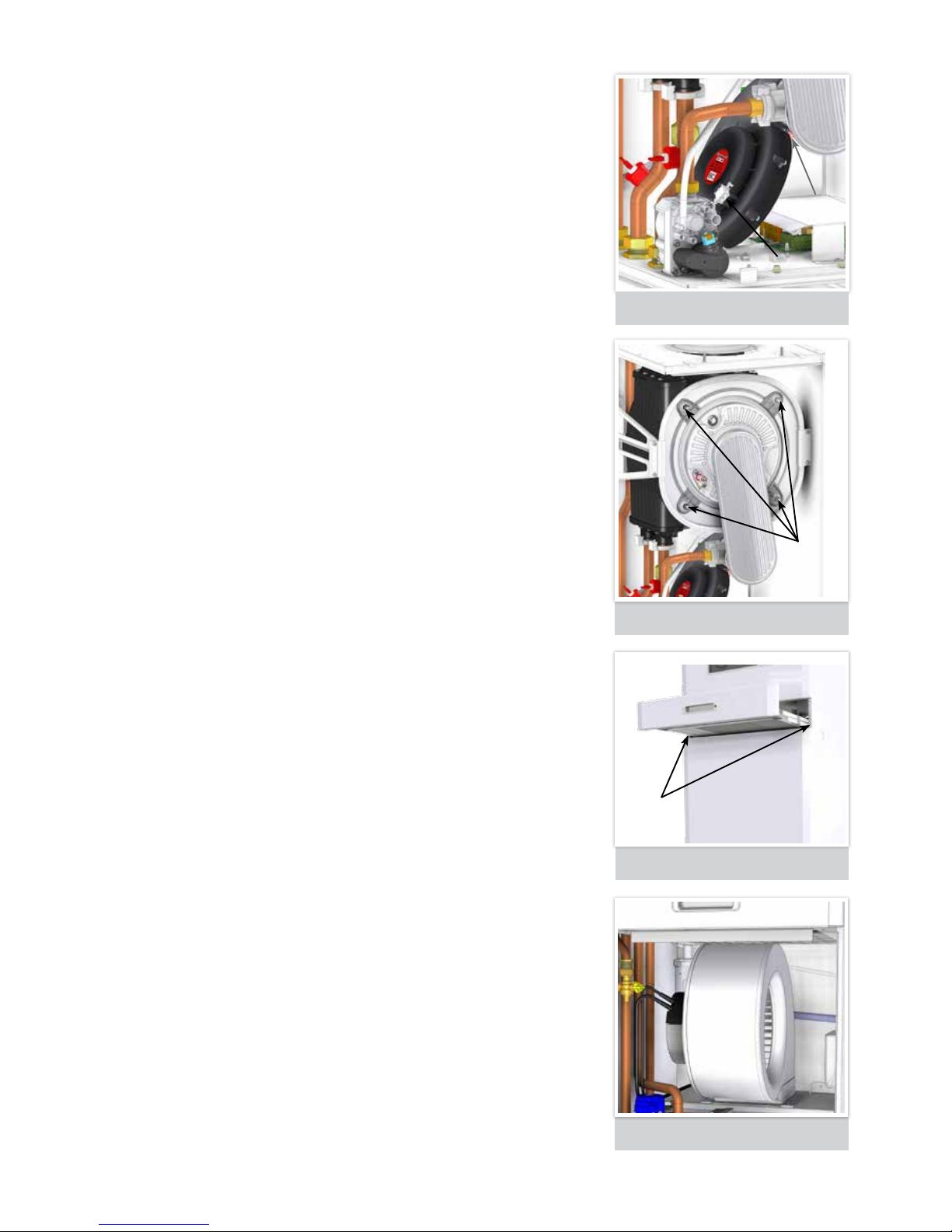
19.8 COMBUSTION AIR FAN
Refer to paragraph 19.5 & 19.6
19.8.1 Disconnect the electrical leads from the fan.
19.8.2 Remove the pressure differential tube.
19.8.3 Remove the red securing clip and slide fan backwards off the
venturi.
19.8.4 Refit in reverse order.
19.9 BURNER ASSEMBLY
Refer to paragraphs 19.5 and 19.6
19.9.1 Remove the gas pipe securing clip from the venturi.
19.9.2 Remove the ignition/detection lead. See Figure 35.
19.9.3 Remove the 4 burner fixing nuts. See Figure 34.
19.9.4 Lift out the burner from the combustion chamber.
19.9.5 Brush off any deposits that may be on the burner with a soft brush.
Inspect the ignition/detection electrode and check the electrode
gaps.
19.9.6 Inspect the sealing gasket around the burner for any signs of
damage. Replace if necessary.
19.9.7 Refit in reverse order.
19.10 WATER HEAT EXCHANGER
Refer to paragraphs 19.5 to 19.8.
19.10.1 Inspect the inside of the combustion chamber, with a soft brush
remove any deposits that may have occurred. Flush with clean
water. DO NOT use any chemicals.
19.10.2 Inspect the heat exchangers insulation at the front and back of
the combustion chamber for any signs of damage, then it must be
replaced.
19.10.3 If there are any signs of damage on the flue outlet then this must be
replaced.
19.10.4 Refit in reverse order.
FIGURE 25.
DOOR REMOVAL
FIXING
SCREWS
CLIP
ELECTRICAL
CONNECTION
FIGURE 24.
BURNER ARM & WATER HEAT EXCHANGER
FIXING
NUTS
FIGURE 23.
COMBUSTION AIR FAN REMOVAL

23
Sales/Spares & Replacement Help Line 01604 762881
FIGURE 29.
CONDENSATE PUMP & TRAP
19.13 AIR HEAT EXCHANGER
Refer to section 19.10
19.13.1 Peel back the magnetic panel to gain access into the air heat
exchanger.
19.13.2 Check the heat exchanger airways are free from obstructions. If
necessary, clean with a vacuum cleaner from the air inspection
panel, taking care to not damage the airways.
CAUTION: THE ELEMENTS OF THE HEAT EXCHANGER ARE VERY FRAGILE.
19.13.3 Check the condition of the external strainer, cleaning as necessary.
19.14 CONDENSATE PUMP
Refer to section 19.10
19.14.1 Disconnect the mains.
a. Disconnect the condensate pipes.
b. Unscrew the 2 screws on the bracket and slide the Condense
Pump out.
c. Be careful as this will contain water.
19.14.2 Check for debris in the pump tank. Remove any material that might
block the condense pipes or condense tube.
19.14.3 Clean the holding tank, filter and floats with warm water and soap.
Rinse completely when finished.
19.14.4 Check the inlet and outlet pipe
ensuring there are no restrictions
in the tubing.
19.14.5 Check filter is in correct position
when refitting and the float is
sitting in the correct position.
19.15 CONDENSATE TRAP
Refer to section 19.10
19.15.1 Remove the Air Circlulation Fan. See paragraph 19.11.
19.15.2 Pull off the rubber pipe noting the position.
19.15.3
Remove the trap and clean by removing the top cap and clean float.
19.15.4 Reassembly and refit in reverse order.
FIGURE 28.
AIR HEAT EXCHANGER
MAGNETIC
PANEL
FIGURE 27.
AIR HEAT EXCHANGER.

www.johnsonandstarley.co.uk
24
FIGURE 32.
BURNER INJECTOR
CLIP
INJECTOR
‘O’ RING
IGNITION
& FLAME
DETECTION
ELECTRODE
VIEWING
PORT
VENTURI/BURNER
INJECTOR
(behind Burner Arm)
BURNER
ARM
HEAT
EXCHANGER
FLUE GAS
SENSOR
FLOW & RETURN
SENSORS
COMBUSTION
AIR FAN
PCB BOARD
GAS
VALVE
PRESSURE
DIFFERENTIAL
TUBE
FIGURE 30.
CONTROL PANEL
20. PARTS REPLACEMENT
20.1 IMPORTANT: Before commencing with any part replacement the appliance should be isolated from the
electrical supply and the gas service cock on the appliance closed.
20.1.1 All parts that are removed should be replaced and refitted in reverse order, ensuring correct seals
are made and wires are connected correctly.
20.1.2 Remove any debris from within the appliance.
20.1.3 When gas-carrying components are replaced the appliance must be tested for gas tightness.
20.1.4 On completion carry out a full functional test of all appliance components and ensure system
controls are operating correctly.
PART REPLACEMENTS WITHOUT DRAINING THE SYSTEM
20.2 CONTROL PANEL
Refer to paragraph 19.5 and 19.6.
20.2.1 Undo the back of the control panel and disconnect the wiring and unplug all lead connections.
20.2.2 Refit in reverse order.
20.2.3 Re-connect all wiring and plug connections.
20.3 BURNER INJECTOR
20.3.1 Refer to paragraph 19.5 and 19.6
20.3.2 Swing down control panel.
20.3.3 Remove the gas pipe securing clip from venturi. See Figure 36.
20.3.4 Undo the gas pipe union from the gas valve.
20.3.5 Withdraw gas pipe from venturi.
20.3.6 Remove injector from gas pipe.
20.3.7 Replace and refit in reverse order.
20.4 COMBUSTION AIR FAN
Refer to paragraph 19.5 and 19.6
20.4.1 Disconnect the electrical leads from the fan.
20.4.2 Remove the pressure differential tube.
20.4.3 Remove the red securing clip and slide fan backwards off the venturi.
20.4.4 Replace and refit in reverse order.
FIGURE 31. HOT WATER COMPARTMENT
25
Sales/Spares & Replacement Help Line 01604 762881
FIGURE 35. ELECTRODE GAP
FIGURE 36. GAS VALVE
FIGURE 34. THERMISTOR SENSOR
FIGURE 33. BURNER ASSEMBLY
20.5 BURNER ASSEMBLY
Refer to paragraph 19.5 and 19.6
20.5.1 Remove the gas pipe securing clip from the venturi.
20.5.2 Unclip the ignition/detection lead.
20.5.3 Remove the 4 burner fixing nuts.
20.5.4 Carefully lift out the burner from the combustion chamber.
20.5.5 Replace the sealing gasket around the burner.
20.5.6 Replace with new burner assembly.
20.5.7 Refit in reverse order.
20.6 FLOW & RETURN THERMISTOR SENSORS
20.6.1 Refer to paragraph 19.5
20.6.2 Unclip the flow thermistor at the front, from the flow pipe and disconnect
the red wire. Withdraw from the heater.
20.6.3 Unclip the return thermistor at the rear, from the return pipe and withdraw it
from the heater.
20.6.4 Disconnect the blue wires.
20.6.5 Reconnect the electrical leads to the new thermistors and re-assemble in
reverse order, ensuring that the thermistors are securely fitted to the pipes
on the thermistor locator tabs as shown.
20.6.6 Check the operation of the heater. See Section 15.
20.7 IGNITION/DETECTION ELECTRODE
20.7.1 Refer to paragraph 19.5
20.7.2 Remove the 2 screws holding the ignition electrode to the combustion
chamber.
20.7.3 Remove the electrode.
20.7.4 Check dimensions as shown. Fit the new ignition electrode, using the new
gasket supplied.
20.7.5 Refit in reverse order.
20.7.6 Check the operation of the heater. See Section 15
20.8 GAS VALVE
20.8.1 Refer to paragraph 19.5 & 19.10.
20.8.2 Unplug the electrical lead and pressure differential tube connection from
the gas control valve.
20.8.3 Undo the union nut on the outlet of the gas control valve, rotate out of the
way.
20.8.4 Undo the gas inlet pipe union at the inlet to the gas control valve.
20.8.5 Remove screws retaining the valve to the diaphragm and lift the valve
forwards.
20.8.6 Fit the new gas control valve ensuring the two sealing washers are in place
and reconnect gas and electrical connections.
20.8.7 Check operation of the heater. See Section 15.
20.9 WARM AIR PCB
20.9.1 Refer to paragraph 19.5
20.9.2 Remove the PCB cover.
20.9.3 Disconnect the wiring at the PCB terminal block.
20.9.4 Release the 4 clips securing the PCB and withdraw the panel.
20.9.5 Replacement and refit is in reverse order.
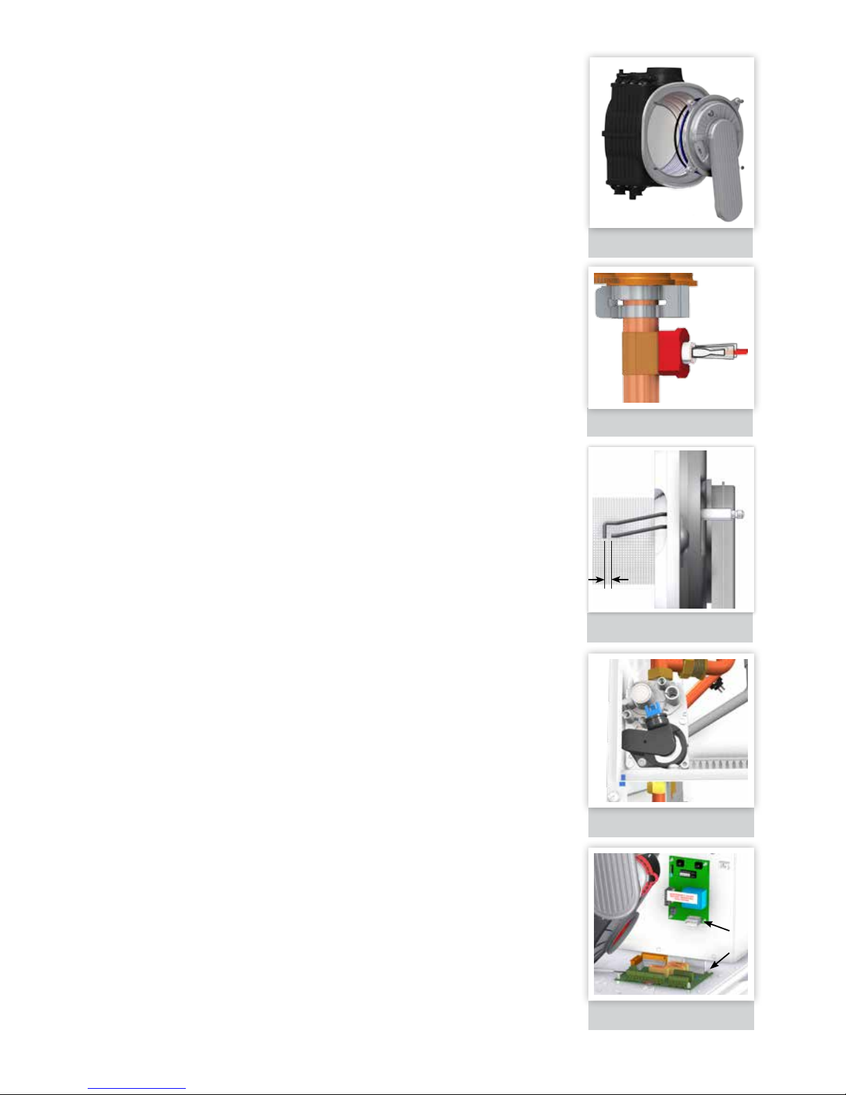
20.10 PCB INTERFACE
20.10.1 Refer to paragraph 19.5
20.10.2 Remove the PCB box cover.
20.10.3 Unplug all lead connections to the PCB assembly
20.10.4 Disconnect all the wires.
20.10.5
Release the 4 corner clips securing the PCB and withdraw the panel.
20.10.6 Fit new PCB and re-connect all plug and wire connections.
20.10.7 Check operation of the
heater. See Section 15.
3.5mm ±1
FIGURE 37. PCB INTERFACE
CORNER
CLIPS

www.johnsonandstarley.co.uk
26
FIGURE 40. AIR CIRCULATION FAN
20.11 AIR CIRCULATION FAN
Refer to paragraph 19.10.
20.11.1 Disconnect the 2 inline connectors on the fan assembly.
20.11.2 Release the screws securing the fan and withdraw.
20.11.3 Replace and refit in reverse order.
20.12 CONDENSATE PUMP
Refer to paragraph 19.10
20.12.1 Disconnect the mains
20.12.2 Disconnect the condensate pipes
20.12.3 Unscrew the 2 screws on the bracket and slide the condense
pump out.
20.12.4 Be careful as this will contain water.
20.12.5 Replace and refit in reverse order.
20.13 CONDENSATE TRAP
Refer to paragraph 19.10
20.13.1 Pull off the rubber pipe noting the position.
20.12.2 Unscrew the top pipe from the trap.
20.13.3 Unclip the trap and replace.
20.13.4 Refit in reverse order.
20.14 DIVERTER ACTUATOR HEAD
Refer to paragraph 19.10
20.14.1 Unplug the electrical connections.
20.14.2 Pull out the retaining clip and lift diverter head from body of the
valve.
20.14.3 Replace and refit in reverse order.
20.14.4 Check the operation of the appliance.
FIGURE 41. CONDENSATE PUMP & TRAP
FIGURE 42. DIVERTER HEAD REMOVAL
PUMP
FIGURE 38. PUMP/DIVERTER ASSEMBLY
WATER FLOW
TEMPERATURE
SENSOR
SCREW
FIGURE 39. AIR WATER HEATER COMPONENTS
AIR
CIRCULATION
FAN
AUTOMATIC AIR
VENT
AIR TO
WATER
HEAT
EXCHANGER
GAS COCK
CONDENSE TRAP
(at the back)
DIVERTER
HEAD
DIVERTER
VALVE
DRAIN VALVE
RETURN FLOW FOR
RADIATORS
RADIATOR
CAPPED
FLOW PIPE

27
Sales/Spares & Replacement Help Line 01604 762881
FIGURE 45.
AIR TO WATER HEAT EXCHANGER REMOVAL
FIGURE 43.
PUMP HEAD REMOVAL
FIGURE 44.
AUTOMATIC AIR VENT REMOVAL
PART REPLACEMENTS BY DRAINING THE SYSTEM
20.15 DRAINING THE APPLIANCE
20.15.1 To drain the appliance, attach a length of hose to the drain point
then open the drain valve.
20.15.2 Replace the necessary component.
20.15.3 After replacement close the drain valve and open all isolation
valves and refill the system.
20.15.4 Ensure that all air locks are expelled, and check for water
soundness.
20.16 PUMP HEAD
Refer to paragraph 19.10. Drain appliance. See section 20.15.
20.16.1 Disconnect the electrical lead from the pump head.
20.16.2 Remove the 4 allen screws securing the pump head and remove.
20.16.3 The Red Dial on the pump head is set to maximim
20.16.4 Replace and refit in reverse order.
20.16.5 Refill and check operation of the appliance.
20.17 DIVERTER CARTRIDGE
Refer to paragraph 19.10 Drain appliance. See section 20.15.
20.17.1 Remove the diverter head.
20.17.2 Pull out the retaining clip and lift out the mechanism.
20.17.3 Replace and refit in reverse order.
20.17.4 Refill and check operation of the appliance.
20.18 AUTOMATIC AIR VENT
Refer to paragraph 19.10 Drain appliance See section 20.15.
20.18.1 Remove the air vent head clip and lift upwards
20.18.2 Replace and refit in reverse order.
20.18.3 Refill and a check operation of the appliance.
20.19 AIR HEAT EXCHANGER
Refer to paragraph 19.10 Drain appliance. See section 20.15.
20.19.1 Disconnect the water flow temperature sensor.
20.19.2 Release the flow and return pipe nuts to loosen off the pipe.
20.19.3 Release the clip and remove the heat exchanger by sliding it
forward.
NOTE: There will still be water in the heat exchanger.
20.19.4 Replacement and refit in reverse order.
20.19.5 Refill and check operation of the appliance.
SCREWS
CLIP
TEMPERATURE
SENSOR
RETAINING
CLIP

www.johnsonandstarley.co.uk
28
21. FAULT FINDING FLOWCHARTS & BLOCKING CODES
Should a fault occur, the boiler will shut down and these error codes will be displayed.
There must be a link
between High Voltage
terminals 1 & 6 and high
voltage terminals 3 & 6.
Make sure both links are
present
MAF STAT CONNECTED NOT CALLING FOR HEAT (HEATER NOT FIRING) WHEN MAF STAT ON MAXIMUM
NO
YES
YES
NO
NO
YES
YES
YES
NO
YES
NO
NO
NO
NO
YES
YES
NO
Is there 230 ~ 250VAC across High Voltage terminals 2 & 4?
Is there 230 ~ 250VAC across High Voltage terminals 1 & 2?
Measure DC voltage (5.1V DC Max.) across Low Voltage terminals 3 & 4
Is measured voltage greater
than 4.7V
Is measured resistance
greater than 11K?
Is measured voltage greater
than 4.7V
Check pipe sensor and
connections. If sound, isolate
from mains & measure
resistance across plug J2 pins
5 & 6
Is measured voltage greater than 4.19V?
Is there an external clock fitted?
Measure DC voltage (5.1V
DC Max.) across Low Voltage
terminals 5 & 6
Check black wire of MAF stat
goes to Low Voltage terminal 3
and red wire of MAF stat goes
to low voltage terminal 4. Ensure
all connections are sound
Check clock is on & measure
output
Check for live supply into clock.
Replace clock if live is present
Is 230 ~ 250VAC present?
Check harness connections
to PCB. If all OK Replace
PCB
Remove MAF stat connections
and link Low Voltage terminals
TPV & 3. Is there 230 ~ 250VAC
across High Voltage terminals
2 & 4?
Open circuit between clock
out & High Voltage terminal
block 1
Unit mains
supply is
missing.
Check spur
e.g. fuse is
intact
Check
connections
to high
voltage
terminals
2 & 3
Problem with switched live output going from High Voltage terminal 3
to switch live of heater
Is there 230 ~ 250VAC across High Voltage terminals 2 & 3?
HOT WATER FAULT FINDING - BLOCKING CODES

29
Sales/Spares & Replacement Help Line 01604 762881
FAN NOT OPERATING WHEN PIPE IS ABOVE 60°C
YES
YES
YES NO
YES
NO
NO
YES
Check for mains going into fan plug
Measure DC voltage (0 to 10V) within Low Voltage fan connector
(blue & yellow)
Is measured voltage greater than 2V?
Check pipe and connections.
If sound, isolate from mains &
measure resistance across plug
J2 pins 5 & 6
Does the actual pipe temp.
match the approx. pipe temp.
for the measured voltage in
Table 4?
Is measured resistance greater
than 11K?
Faulty fan
Faulty
PCB
Check sensor is fitted correctly. If
it is then replace sensor.
Faulty PCB
PCB is not seeing sensor.
Confirm by measuring sensor
resistance. Replace sensor
if resistance is greater then
28K.
NO
Make sure mains is present across High Voltage terminals 2 & 3
Is the MAF stat connected?
Is fan now running?
Link out low voltage terminals 3 & 4.
Measure voltage across
Low Voltage
terminals 5 & 6
Is measured voltage greater than 4.7V DC?
Make sure clock or room stat supplies mains voltage to high voltage
terminals 1 & 2. No mains - no fan operation (except for summer vent)
DC VOLTAGE
ACROSS PIPE
SENSOR
APPROX. PIPE
TEMP. °C
DC VOLTAGE
ACROSS PIPE
SENSOR
APPROX. PIPE
TEMP. °C
DC VOLTAGE
ACROSS PIPE
SENSOR
APPROX. PIPE
TEMP. °C
DC VOLTAGE
ACROSS PIPE
SENSOR
APPROX. PIPE
TEMP. °C
3.24 10 2.13
33
1.26 56 0.73
79
3.19 11 2.08 34 1.23 57 0.71 80
3.14 12 2.04 35 1.20 58 0.70 81
3.09 13 1.99 36 1.17 59 0.68 82
3.04 14 1.95 37 1.15 60 0.66 83
2.99 15 1.91 38 1.12 61 0.65 84
2.94 16 1.87 39 1.09 62 0.63 85
2.89 17 1.83 40 1.07 63 0.63 86
2.84 18 1.79 41 1.04 64 0.60 87
2.79 19 1.75 42 1.02 65 0.59 88
2.75 20 1.71 43 0.99 66 0.58 89
2.70 21 1.67 44 0.97 67 0.56 90
2.65 22 1.63 45 0.95 68 0.55 91
2.60 23 1.59 46 0.92 69 0.54 92
2.55 24 1.56 47 0.90 70 0.53 93
2.50 25 1.52 48 0.88 71 0.51 94
2.45 26 1.49 49 0.86 72 0.50 95
2.40 27 1.45 50 0.84 73 0.49 96
2.36 28 1.42 51 0.82 74 0.48 97
2.31 29 1.39 52 0.80 75 0.47 98
2.26 30 1.35 53 0.78 76 0.46 99
2.22 31 1.32 54 0.76 77 0.45 100
2.17 32 1.29 55 0.75 78 TABLE 6

www.johnsonandstarley.co.uk
30
IGNITION LOCKOUT
OVERHEAT LOCKOUT
FALSE FLAME LOCKOUT
YESYES
YES
NO
YES
YES
YES
NO
NO
NO
Check siphon and condensate drain pipe
work for blockage and rectify if necessary. Is
heater working?
Check routing and integrity of internal heater
wiring.
Check the gas supply
Check wiring connection from gas valve to
PCB for continuity. If the wiring is OK then
replace the PCB.
Replace the pump, the reset the heater.
Replace the gas valve
Replace board and harness as necessary.
Replace PCB and associated harness as
necessary.
NO
NO
YES
YES
YES
YES
NO
NO
NO
NO
NO
NO
YES
NO
Check the pressure control pipe between fan
and gas valve for continuity, visual condition,
replace as necessary. Is heater working?
Check the Flow & Return thermistors.
Check resistance using a suitable multi-meter
connection across the thermistor’s terminal
pins
RESET PROCEDURE
To reset the heater,
press the reset button.
Is the gas pressure available at the inlet
(>18mbar)?
Fill & vent the system & open all isolation
valves, then reset heater.
Check routing and integrity of the internal boiler
wiring is working OK. Check condition of the Flame
Sensor Electrode and replace if necessary.
Is approx 24 VDC supply available at the
gas valve?
Check that the pump is rotating freely. Is the
differential now below 20°C?
Replace flame detection electrode.
Unplug the gas valve. Is resistance between
outside pins 114Ω
Reset the heater.
Check board and associated harness for:
continuity and visual condition. Are these
functioning correctly?
Check ignition and associated harness for :
continuity visual condition and position. Are
these functioning correctly?
Replace the Gas Valve.
If the heater is reset does the heater ignite for
a short time and then extinguish?
Is the heater & CH system filled with water
and all isolation & radiator valves open?
Reset the heater. Is the heater working?
Check the detection electrode and associated
harness for: continuity, visual condition and
position. Check if the condensate pipe is
blocked. Replace if necessary.
Is the Flow/Return differential across the
heate
r in excess of 30°C?
Remove ignition lead and earth tag. Is
there continuity between the terminal pins
connected to the electrode?
Should a fault occur, the heater will shut down and these blocking codes will be displayed.
HOT WATER FAULT FINDING - BLOCKING CODES

31
Sales/Spares & Replacement Help Line 01604 762881
FAN FAULT
VALVE FEED BACK ERROR
FLAME CIRCUIT FAILURE
YES
YES
YES
Replace the Fan.
NO
NO
NO
Rectify wiring & connections
Replace Gas Valve.
Replace the PCB.
Does the wiring from the fan to the PCB have secure connections at both
ends and has not deteriorated? Does the wiring have continuity?
Unplug the Gas Valve. Is there resistance between pins 114Ω.
Replace the PCB.
Is there 230Vac at the Blue Brown connections to the 3 way connection on
the fan
Replace Board.
FLOW/RETURN SENSOR CALIBRATION CHECK
EEPROM LOCKOUT
YES
NO
NO
Fill and vent the system and open all isolation
valves, check as supply, then reset heater
Replace the Sensor.
Is the heater & CH system filled with water & all isolation valves open?
Replace the PCB.
Reset the
heate
r. Is the heater working?
SENSOR STUCK LOCKOUT
YES
YES
YES
YES
Check resistance at 2 different temperatures. See Graph Figure 46.
Replace the PCB.
Does the flow pipe temperature increase by more than 1°C within 30
seconds of ignition?
NO
NO
NO
NO
Fill and vent the system and open all isolation
valves, check as supply, then reset heater.
Secure Sensors and reset.
Replace Sensor.
Check pump is rotating.
Is the heater filled with water and all isolation valves open?
Are the sensors secured firmly to the flow and return pipes?

www.johnsonandstarley.co.uk
32
ADC LOCKOUT
Replace the PCB.
RETURN THERMISTOR FAULT
YES
YES
Replace the PCB.
NO
NO
Fit a new Thermistor.
Check and replace wiring as necessary.
Remove the return thermistor from the CH return pipe and disconnect the
wires.
Check the resistance using a suitable multi-meter connected across
the thermistor’s terminal pins. Is the thermistor valve correct?
Is the wiring securely connected to the low voltage 9 way connector X5 on
the PCB?
FLOW THERMISTOR FAULT
YES
YES
Is the wiring securely connected to the low voltage 9 way connector X5 on
the PCB?
NO
NO
Securely connect the wiring to the flow Thermistor.
Fit new Thermistor.
Is the wiring securely connected to the Flow thermistor?
Disconnect the wiring from the Flow Thermistor.
Check the resistance using a suitable multi-meter connected across the
Thermistor’s terminal pins.
Is the Thermistor value correct?
Check & replace as necessary.
YES
NO
Replace the PCB.
FIGURE 51. SENSOR TEMPERATURE/RESISTANCE DIAGRAM
0
5000
10000
15000
20000
25000
30000
0 20 40 60 80 100 120
Ohms
o
C
Sensor temperature/resistance diagram

33
Sales/Spares & Replacement Help Line 01604 762881
EXHAUST SENSOR FAULT
BLOCKING CODES
YES
YES
YES
Check wiring & connections to 9 way connector on PCB X5.
Replace PCB.
NO
NO
NO
Fill and vent the system and open all isolation
valves, check as supply, then reset heater
Replace the flue thermistor.
Secure to PCB.
Is the heater & CH system filled with water and all isolation & radiator
valves open?
Check flue thermistor.
Check resistance using a suitable multi-meter
connection across the thermistor’s terminal pins. (Refer to graph on E03).
FLUE TEMPERATURE SENSOR LOCKOUT
YES
YES
YES
Is the wiring secure to 9 way connector X5 on Interface PCB
Replace the PCB
NO
NO
Connect the wiring.
Secure connection.
Is the wiring securely connected to sensor?
See graph Figure 51.
NO DISPLAY
YES
YES
Replace the PCB
NO
NO
Supply power to heater.
Connect the wiring from the terminal block to the
Main PCB securely.
Is there 230VAC to the heater at L & N?
Is the wiring from the terminal block to the main PCB connected securely?
REMOTE RESET LOCKOUT
Turn power on and off, reset heater. The heater will correct original lockout
error.
VALVE FEED BACK ERROR
CONDENSATE PUMP SAFETY FLOAT SWITCH
YES
YES
NO
NO
NO
Correct electrical fault.
Check power supply.
Replace condense pump.
Is mains supply to heater between 190V - 256V @ 50 Hz?
Check power to the pump?
Replace PCB.
Check for any blockages, restrictions or frozen pipes.
Should a fault occur, the boiler will shut down and these blocking codes will be displayed.

www.johnsonandstarley.co.uk
34
22. FUNCTIONAL WIRING DIAGRAMS
bn
bn
bu
bn
pk
ye
-ve
gn
bn
bu
bk
or
bk
bn
bn
bn
bk
bu
ye
bu
bu
wh
wh
bk
rd
rd
bk
rd
bu
bu
bn
bn
bu
bu
2
1
3
4
2
1
6
7
8
5
3
4
2
1
6
7
8
5
9
10
21
2223242526
27
2829303132
3
4
2
1
678
9
5
3
4
2
1
6
7
5
HT
1
3
1
2
1
2
1
2
1
2
1
2
1
2
1
rd
bk
2
1
3
4
2
1
3
4
2
1
3
4
2
1
2
1
4
3
5
6
2
13
2
1
3
33
34
35
36
37
38
39
41
42
43
44
40
87654321
1211109
16151413 20191817
3
4
2
1
GAS VALVE
PIPE
SENSOR
(FLOW)
COMBUSTION
AIR FAN
NEXSYS PCB
AIR
CURCULATION
FAN
bn
bn
bk
bk
gnye
REMOVE LINK WIRES WHEN
REMOTE CLOCK FITTED
LABEL REF No. 1000-2222920-2
PIPE SENSOR
RETURN LINE
MIN FAN
ADJ
PIPE
SENSOR
CONDENSE
FLOAT
SWITCH
INTERFACE
PCB
CONDENSATE
PUMP
gnye
gnye
gnye
gnye
gnye
bu
wh
wh
bu
bu
wh
wh
rd
rd
rd
rd
rd
HT CONNECTOR
THERMAL
FUSE
rd
rd
ye
ye
gy
gy
bk
bk
bk
MAINS
INPUT
53
52
51
3
4
2
1
C1
C2
C9
PIPE
SENSOR
(RETURN)
CLEANFLOW
(optional)
AQUAIR PCB
PUMP/DIVERTER
VALVE
CONDENSING
HEAT EXCHANGER
C8
C6
FLUE
SENSOR
C18
X7
X2
X3
X12
J1
J2
J3
C11
C7
C19
C14
J4
J2
C12
C3
C4
C5
J3
C16
EARTH
TAB
EARTH CHASSIS
VOLT FREE STAT
CYLINDER
STAT
MAF STAT
SUMMER
VENT
C10
X4
X5
C13
X11
50
49
48
47
46
45
SUMMER
VENT
CYLINDER
STAT
HW / SL
CH / SL
L
CLOCK
CONDENSE
PUMP
N
L
N
- MAF +
STAT
VOLT FREE
STAT
FIGURE 46. WARMCAIR C10DW COMBINED WIRING DIAGRAM
COLOUR
Red RD Brown BN
White WH Grey GY
Yellow YE Pink PK
Black BK Violet VT
Orange OG Green/Yellow GNYE
Blue BU

35
Sales/Spares & Replacement Help Line 01604 762881
23. DIMENSIONS
550
77
722
1350
1480
90
537
628
181
194
335
123
341
164
399
483
42
42
90
146
198
77
251
327
49
302
286
222
31
57
416
18
FIGURE 47. WARMCAIR C20DW COMBINED DIMENSIONS

www.johnsonandstarley.co.uk
36
HOT WATER
FLOW FROM
HEAT SOURCE
HOT WATER
RETURN FROM
HEAT SOURCE
24. SPARES DIAGRAMS
FIGURE 48. WARMCAIR C10DW COMBINED EXPLODED DIAGRAMS
6
3
3
21
29
12
20
27
26
23
25
28
24
18
30
15
1
4

37
Sales/Spares & Replacement Help Line 01604 762881
ITEM DESCRIPTION QTY PART No. G. C. No.
1
PCB Nexsys Boiler Control
1
1000-0527185
J24-704
2
PCB Assembly (Aquair)
1
1000-0526275
J24-745
3
PCB Interface
1
1000-0527035
J21-741
4
PWM High Efciency Pump Head
Includes 5
1 1000-0531015
5
Pump Head Gasket
1 1000-1508935 J21-281
6
Burner Arm Assembly
Includes 7 - 11
1 1000-0711815 J21-311
7
Burner Arm Fibre Seal Braid Gasket
1 1000-1509000 J21-236
8
Burner Door Seal
1 1000-1509860 J21-237
9
Venturi Gasket
1 1000-1508630 J21-243
10
M5 Screws
2 1000-3003330 J21-244
11
M5 Nuts
2 1000-3003820 J21-238
12
Ignition/Detection Electrode
Includes 13 & 14
1 1000-0711785 J21-229
13
Electrode Gasket
1 1000-2501275 H38-677
14
M4 x 8 Torx Screws
2 1000-3003395 J21-240
15
Gas Valve
Includes 16 & 17
1 1000-0710925 J21-261
16
Sealing Washer
2 1000-3004280 J21-231
17
M4 X 10 Screws
2 1000-3000100
18
Combustion Air Fan
Includes 19
1 1000-0526415 J21-313
19
Combustion Air Fan Clip
1 1000-0711745 J21-245
20
Venturi (034)
Includes 9
1 1000-0710785 J21-671
25. LIST OF SPARES
5
9
9
8
11
16
17
19
13
13
14
7

www.johnsonandstarley.co.uk
38
ITEM DESCRIPTION QTY PART No. G. C. No.
21
Injector (4.75)
Includes 22
1 1000-07111135 J21-234
22
‘O’ Ring
1 1000-2501860 J21-235
23
Air Circulation Fan
1
1000-0525255
J24-686
24
Flue Gas Sensor
1
1000-0526525
J21-253
25
Air To Water Heat Exchanger
1
AQ20-0138005
J24-
26
Condensate Pump
1
1000-0023085
J24-746
27
Condensate Trap
1
1000-0024525
J24-749
28
Return Water Temperature Sensor
(water to air heat exchanger)
1
1000-0526505
J24-758
29
Flow/Return Water Temperature Sensor
1
1000-0526515
J21-334
30
Air Filter
1
C20DW-0138005
J24-716
22

39
Sales/Spares & Replacement Help Line 01604 762881
26. LIST OF ANCILLARIES
WARMCAIR C10DW ANCILLARY’S
Description Product Code
1
Cleanow Air Filter
CF20W
2 Filter Replacement Pads
(Pack of 6)
A0212X0212
3
Return Air Kit
RAK20W
4
Base Duct Kit
WBX20W
4

www.johnsonandstarley.co.uk
40
NOTES

41
Sales/Spares & Replacement Help Line 01604 762881
Code Of Practice
For the installation, commissioning and servicing
of domestic heating and hot water products
Benchmark places responsibilities on
both manufacturers and installers.*
The purpose is to ensure that
customers** are provided with the
correct equipment for their needs, that it
is installed, commissioned and serviced
in accordance with the manufacturer’s
instructions by competent persons
and that it meets the requirements of
the appropriate Building Regulations.
Installers are required to carry out work
in accordance with the following:
Standards of Work
• Be competent and qualified to undertake the work
required.
• Install, commission, service and use products in
accordance with the manufacturer’s instructions provided.
• Ensure that where there is responsibility for design work,
the installation is correctly sized and fit for purpose.
• Meet the requirements of the appropriate Building
Regulations. Where this involves notifiable work be a
member of a Competent Persons Scheme or confirm that
the customer has notified Local Authority Building Control
(LABC), prior to work commencing.
• Complete all relevant sections of the Benchmark
Checklist/Service Record when carrying out
commissioning or servicing of a product or system.
• Ensure that the product or system is left in a safe
condition and, whenever possible, in good working order.
• Highlight to the customer any remedial or improvement
work identified during the course of commissioning or
servicing work.
• Refer to the manufacturer’s helpline where assistance is
needed.
• Report product faults and concerns to the manufacturer
in a timely manner.
Customer Service
• Show the customer any identity card that is relevant to
the work being carried out prior to commencement or on
request.
• Give a full and clear explanation/demonstration of the
product or system and its operation to the customer.
• Hand over the manufacturer’s instructions, including the
Benchmark Checklist, to the customer on completion of
an installation.
• Obtain the customer’s signature, on the Benchmark
Checklist, to confirm satisfactory demonstration and
receipt of manufacturer’s instructions.
• Advise the customer that regular product servicing is
needed, in line with manufacturers’ recommendations,
to ensure that safety and efficiency is maintained.
• Respond promptly to calls from a customer following
completion of work, providing advice and assistance by
phone and, if necessary, visiting the customer.
• Rectify any installation problems at no cost to the
customer during the installer’s guarantee period.
* The use of the word “installer” is not limited to installation itself and covers
those carrying out installation, commissioning and/or servicing of heating
and hot water products, or the use of supporting products (such as water
treatment or test equipment).
**Customer includes householders, landlords and tenants.
© Heating and Hotwater Industry Council (HHIC)
www.centralheating.co.uk

This Commissioning Checklist is to be completed in full by the competent person who commissioned the wsnn air unit and associated
equipment as a means of demonstrating compliance with the appropriate Building Regulations and then handed to the customer to keep for
future reference
Failure to Install and commission this equipment to the manufacturer's instructions may Invalidate the warranty but does not affect statutory rights.
CONDENSING WARM AIR HEATING AND WATER HEATING COMMISSIONING CHECKLIST
Customer name: Telephone number:
Address:
Warm Air Unit Make and Model:
Warm Air Unit Serial Number:
Commissioned by (PRINT NAME): Gas safe register number:
Company name: Telephone number:
Company address:
Commissioning date:
CONTROLS (tick the appropriate boxes)
Time and temperature control to heating
Room thermostat and programmer/timer Programmable Roomstat
Load/weather compensation Optimum start control
Heating zone control Fitted Not required
WARM AIR HEATER
Has the system been balanced in accordance with the heater manufacture's instructions? Yes No
Was an anemometer used? Yes No
Yes No
WARM AIR HEATING: measure and record:
Bumer operating pressure (at maximum rate) mbar
Heat input kW
Temperature difference between return air inlet and nearest outlet °C
WATER HEATING: (If fitted)
Water inlet temperature
Water outlet temperature
°C
°C
CONDENSATE
The condensate drain has been installed in accordance with the manufacture's instructions and/or BS 5546/BS6798 Yes
INSTALLATION
The heating and hot water system complies with the appropriate Building Regulations Yes
The system and associated products have been installed and commissioned in accordance with the manufacturers instructions Yes
Yes
The manufacturer's literature, including Benchmark Checklist and Service Record, has been explained and left with the customer Yes
Commissioning Engineer’s Signature
Customer’s Signature
*
© Heating and Hotwater Industry Council (HHIC)
www.centralheating.co.uk
www.centralheating.co.uk

www.centralheating.co.uk
It is recommended that your heating system is serviced regularly and that the appropriate Service Interval Record is completed.
Service Provider
Before completing the appropriate Service Record below, please ensure you have carried out the service as described in the manufacturer’s instructions.
SERVICE RECORD
SERVICE 01
Date:
Engineer name:
Company name:
Telephone No:
Gas safe register No:
Record:
At max. rate: CO ppm AND CO² %
At min. rate:
(Where Possible) CO ppm AND CO
²
%
Comments:
Signature
SERVICE 02
Date:
Engineer name:
Company name:
Telephone No:
Gas safe register No:
Record:
At max. rate: CO ppm AND CO² %
At min. rate:
(Where Possible) CO ppm AND CO
²
%
Comments:
Signature
SERVICE 03
Date:
Engineer name:
Company name:
Telephone No:
Gas safe register No:
Record:
At max. rate: CO ppm AND CO² %
At min. rate:
(Where Possible) CO ppm AND CO
²
%
Comments:
Signature
SERVICE 04
Date:
Engineer name:
Company name:
Telephone No:
Gas safe register No:
Record:
At max. rate: CO ppm AND CO² %
At min. rate:
(Where Possible) CO ppm AND CO
²
%
Comments:
Signature
SERVICE 05
Date:
Engineer name:
Company name:
Telephone No:
Gas safe register No:
Record:
At max. rate: CO ppm AND CO² %
At min. rate:
(Where Possible) CO ppm AND CO
²
%
Comments:
Signature
SERVICE 06
Date:
Engineer name:
Company name:
Telephone No:
Gas safe register No:
Record:
At max. rate: CO ppm AND CO² %
At min. rate:
(Where Possible) CO ppm AND CO
²
%
Comments:
Signature
SERVICE 07
Date:
Engineer name:
Company name:
Telephone No:
Gas safe register No:
Record:
At max. rate: CO ppm AND CO² %
At min. rate:
(Where Possible) CO ppm AND CO
²
%
Comments:
Signature
SERVICE 08
Date:
Engineer name:
Company name:
Telephone No:
Gas safe register No:
Record:
At max. rate: CO ppm AND CO² %
At min. rate:
(Where Possible) CO ppm AND CO
²
%
Comments:
Signature
SERVICE 09
Date:
Engineer name:
Company name:
Telephone No:
Gas safe register No:
Record:
At max. rate: CO ppm AND CO² %
At min. rate:
(Where Possible) CO ppm AND CO
²
%
Comments:
Signature
SERVICE 10
Date:
Engineer name:
Company name:
Telephone No:
Gas safe register No:
Record:
At max. rate: CO ppm AND CO² %
At min. rate:
(Where Possible) CO ppm AND CO
²
%
Comments:
Signature
*All installations in England and Wales must be
to Local Authority Building Control (LABC) either directly or through a
Competent Persons Scheme. A Building Regulations Compliance
will then be issued to the customer.
© Heating and Hotwater Industry Council (HHIC)

Johnson & Starley Ltd
Rhosili Road, Brackmills,
Northampton NN4 7LZ
sales@johnsonandstarley.co.uk
marketing@johnsonandstarley.co.uk
Reception/Customer Service
01604 762881
Fax
01604 767408
Anniversary 1922 - 2012
 Loading...