

Johnson & Starley RenoXtra 30CA, RenoXtra 37C, RenoXtra 30CP, RenoXtra 37CP, RenoXtra 30C Installation, Maintenance And Servicing Instructions
Page 1
Johnson & Starley
®
R E L I A B I L I T Y Y O U C A N T R U S T
The Jo hns on & S tar ley Re no ran ge has an
ene rgy ra tin g A on a sca le of A t o G .
For mor e i nfo rma tio n s ee
www.b oil ers .or g.u k
Thi s i s a ce rti fic ati on mar k.
Publication No. ZZ 1311-5 October 2009
Product Identification No: 87B 074
COMBI
SERIES
Xtra High Efficiency
Combination
Boilers
INSTALLATION, MAINTENANCE &
SERVICING INSTRUCTIONS
Natural Gas G20:
RenoXtra 30CA - GC No: 47-416-05
RenoXtra 37C - GC No: 47-416-06
Propane G31 Variant:
RenoXtra 30CP - GC No: 47-416-07
RenoXtra 37CP - GC No: 47-416-08
www.johnsonandstarley.co.uk
Page 2

CONTENTS
1. Features 3
2. Br ief D escrip tion 3
3. Bu ildin g Stan dards & Reg ulati ons 4
4. Sa fety & Gas Infor mation 4
5. Pr epara tion 5
6. Techn ical Data 5
7. Dim ensio n & Posit ioning 7
8. Hea ting System 8
9. Fit ting 11
10 . F lue In struc tions 12
11 . Co ndens ate Dr ain 20
12 . El ectri cal 21
13 . Functional Flow Diagra m 22
14 . Wir ing Diagram 23
15 . Co mmiss ioning 24
16 . Ha nding Over 24
17 . Se rvici ng 25
18 . De fect Diagno sis 27
19 . Fault Findi ng 29
20 . Parts Repla cemen t 30
21 . Li st of Spare s 34
22 . Ex plode d Diag ram 35
23 . Im porta nt Inf ormat ion 36
24 . Be nchma rk Che cklis t & Se rvice Recor d 37
THE BENCHMARK SCHEME
In order to comply with Building Regulations Part L (Part J in Scotland) the boiler
MUST be fitted in accordance with the manufacturer’s instructions.
Benchmark places responsibilities on both manufacturers and installers. The
purpose is to ensure that customers are provided with the correct equipment for
their needs, that it is installed, commissioned and serviced in accordance with the
manufacturer’s instructions by competent persons and that it meets the requirements
of the appropriate Building Regulations. The Benchmark Checklist can be used to
demonstrate compliance with Building Regulations and should be provided to the
customer for future reference.
Installers are required to carry out installation, commissioning and servicing work in
accordance with the Benchmark Code of Practice which is available from the Heating
and Hotwater Industry Council who manage and promote the Scheme.
Visit www.centralheating.co.uk for more information.
PLEASE READ THESE INSTRUCTIONS CAREFULLY
BEFORE STARTING INSTALLATION
LEAVE THESE INSTRUCTION WITH THE USER OR
AT THE GAS METER AFTER INSTALLATION
In the interest of continuous development Johnson and Starley reserve the right to change
specification without prior notice Johnson and Starley prides itself on it’s ability to supply spare
parts quickly and efficiently.
If your service engineer indicates a problem in obtaining a spare part, advise him to contact
Johnson and Starley Spares Department.
www.johnsonandstarley.co.uk
2
Page 3
1. FEATURES
Appliance Classification.
This appliance is tested and certified by G.L.
Industrial Services UK Ltd for use of type C13, C33,
C53. natural gas.
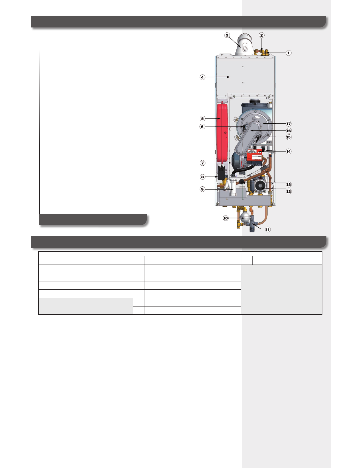
FEATURES
1 Warm Water Return
2 Cold Water supply
3 Flue Turret
4 Gas Saver Unit
5 Expansion Vessel
6 Ignition Electrode
7 Fan/Venturi Assembly
8 Electrical Connection Harness
9 Trap Assembly
10 Shock Arrester
11 Blending Valve
12 Pump
13 Pressure Transducer
14 CBVC
15 Detector Electrode
16 Gas/Air Duct
17 Heat Exchanger
2. BRIEF DESCRIPTION
2.1 The RenoXtra appliance is a high efficiency combination boiler that is
designed to provide the use with both central heating and domestic
hot water on demand. Its design is such that it is room sealed, taking
combustion air from outside and expelling the products of combustion
to the outside again. The heat exchanger is constructed of stainless
steel, which is corrosion free. Flueing options ensure that the appliance
can be installed in many locations within a building.
2.2 The appliance is controlled by fully featured microprocessor based
electronics that monitor each of the operational procedures. An
LCD display indicates the operational state of the appliance which
illuminates for a short period when the user control is operated. This
starts with the full sequence automatic ignition and continues with
monitoring the demand requirements of either the central heating or the
domestic hot water.
2.3 Whilst the appliance is in pre-heat mode it maintains a limited
temperature in the heat exchanger in order to quickly satisfy any
domestic hot water demand. Should any fault occur the appliance will
be shutdown to a safe condition with the fault code being displayed on
the LCD panel.
3
Telephone: 01604 762881
CONTENTS CARTON 1 CONTENTS CARTON 2 CONTENTS CARTON 3
1 Wall Pla te 1 RenoXtra 30CA or Reno Xtra 3 7C Boil er 1 Gas Save r
2 Side Pan els 2 Blendin g Valve, S hock A rresto r and E lbows
3 Front D oor Pan el 3 Control Modul e (inc luding MMI, d isplay and co ntrols )
4 Paper Templat e 4 Wall Jig
5 Raw plu g/Scre w Pack 5 Install ation Instru ctions (inc. Benchm ark Log book)
Table 1
6 Users I nstruc tions
7 Guarant ee Car d
FIGU RE 1
RENOXTRA FEATURES
Page 4

3. BUILDING STANDARDS & REGULATIONS
This appliance must be installed in accordance with the current editions of:
• Building Standards (Scotland) (Consolidation) Regulations.
• Building Regulations
• Gas Safety (Installation and Use) Regulations (as amended)
• BS 7671 Institute of Electrical Engineers (I.E.E) Wiring Regulations
• BS 6891 Installation of Low Pressure Gas Pipework of up to 28 mm
(R1) in domestic premises (2nd family gases).
• BS 5440 Pt. 1 (Flues for Gas Appliances)
• BS 5440 Pt. 2 (Air Supply for Gas Appliances)
• Model and Local Authority Byelaws
• BS 5546 Installation of Domestic Hot Water Supplies
This appliance has been Tested and Certified in order to meet the necessary
European Directives and comply with the latest Building Regulations,
including the efficiency requirements of the SEDBUK scheme.
Efficiency of Hot Water Boilers Directive 92/42/EEC
Gas Appliance Directive 90/396/EEC
Low Voltage Directive 93/68/EEC
Electromagnetic Compatibility Directive 92/31/EEC
No modifications to this appliance should be made, unless they are fully
approved by the manufacturer.
The manufacturers instructions supplied must not be taken as overriding any
statutory requirements.
A two year manufacturers warranty applies to this appliance.
It is important that the system is flushed thoroughly before the applianceIt is important that the system is flushed thoroughly before the appliance
is left to operate (as recommended in BS 7593) in order to maintain an
efficiently operating heating system. For replacement installations, the
system MUST be flushed with the old boiler in situ, in order to prevent the
RenoXtra becoming a trap for system debris. Once the system has been
flushed, an inhibitor (suitable for stainless steel heat exchangers) should be
added. Appropriate inhibitors are available, for example Sentinel, Fernox and
Salamader.
Failure to carry out the above procedure will invalidate the
guarantee!
IMPORTANT: STATUTE LAW DEFINES THAT ALL GAS
APPLIANCES MUST BE INSTALLED BY COMPETENT
PERSONS, (i.e. GAS SAFE REGISTERED INSTALLERS) IN
ACCORDANCE WITH THE GAS SAFETY (INSTALLATION
AND USE) REGULATIONS (CURRENT EDITION). FAILURE
TO COMPLY WITH THESE REGULATIONS MAY LEAD TO
PROSECUTION.
4. SAFETY & GAS INFORMATION
4.1 SAFETY INFORMATION
4.1.1 Ensure the mains supply voltage, frequency, number of phases and
power rating comply with details on the rating label.
4.1.2 All wiring must be in accordance with the appropriate standards. The
equipment must be supplied with a double pole isolator switch.
4.1.3 Ensure safety regulations and practices are adhered to when installing
and using this equipment
4.1.4 The weight of this appliance exceeds that recommended for a one-
man lift. It will therefore be necessary to gain assistance at
times during the installation procedure.
4.1.5 It should be noted that this appliance may contain sharp edges. Care
MUST be taken when handling the appliance to prevent injury. We
advise the engineer to wear suitable P.P.E.
4.1.6 Once the appliance has been fired beware that certain parts will be hot
to the touch.
4.1.7 Do not install flues during rain, high winds or in severe weather
conditions.
www.johnsonandstarley.co.uk
4
Page 5

4.2 GAS INFORMATION
4.2.1 Gas Categories
a. The appliance is certified as a CAT II 2H 3P appliance. This allows
conversion between Natural gas (G20) and LPG (G31). Their supply
pressures are 20 mbar and 37 mbar respectively.
b. For Natural gas to LPG conversion kit number: NG30 (complete with
instructions) is available.
c. For LPG to natural gas conversion kit number LPG30 (complete with
instructions) is available.
4.2.2 Gas Supply
a. The gas installation must be completed in accordance with the
relevant standards (B S 6891).
b. The supply must be capable of providing a steady inlet working
pressure to the appliance of 20 mbar at a rate of 3.2 m³/h
(RenoXtra 30CA) or 3.92 m³/h (RenoXtra 37C) (Calculated with a
Gas CV of 38.7 MJ/m³)
c. The installation must be tested for gas tightness using suitable
methods. The Pipework should also be purged of air in
accordance with the IG Publication Standard.
GAS LEAKS
DO NOT OPERATE ANY ELECTRICAL SWITCHES, OR USE A NAKED FLAME TURN OFF THE GAS
SUPPLY. VENTILATE THE AREA BY OPENING DOORS AND WINDOWS. CALL THE NATIONAL GAS
EMERGENCY SERVICE ON 0800 111999
5. PREPARATION
5.1 Make sure all the electrical cables are in place.
5.2 Water connections.
5.3 Gas connections are in place.
5.4 The wall surface where boiler is being fixed is smooth and flat.
5.5 Giving consideration to the flue position.
5.6 Give consideration to the overall height.
5
Telephone: 01604 762881
RenoXtra 30CA RenoXtra 37C
Maximum Lift Weight 34.45 kg 36.5 kg
Gas Connection 15 mm copper
Domestic hot water 15 mm copper
Heating flow and return 22 mm copper
Safety valve discharge 15 mm copper
Condensate Drain 21.5mm plastic overflow pipe
Maximum heating system water content using fitted expansion vessel,
pressurised at 1 bar.
73 Litres
Electrical supply 230V
Electrical rating 145W
IP classification IP 40
External fuse rating 3 A
Expansion vessel capacity 8 Litres
Expansion vessel initial charge pressure 1.0 bar
Heating system minimum pressure 0.7 bar
DHW max. inlet pressure 5 bar
Minimum inlet pressure for maximum DHW flow rate 1.0 bar
Minimum inlet pressure for appliance to operate 0.2 bar
Maximum DHW flow rate at 35° rise 12.3 l/m 15.9 l/m
Minimum domestic hot water flow rate 2.2 l/m
Maximum flow temperature. 63°C
DHW Specific Rate 14.3 l/min 18.6 l/m
Ball valves are fitted in water and gas connections
For larger systems use an additional expansion vessel
TABLE 2
GENE RAL DATA
Page 6
PLEASE NOTE:
Natural Gas (G20) consumption is calculated using gross CV of 38.7 MJ/m³ or 34.9
MJ/m³ net.
LPG (G31) consumption is calculated using gross CV of 95.6 MJ/m³ or 88.0 MJ/m³
net.
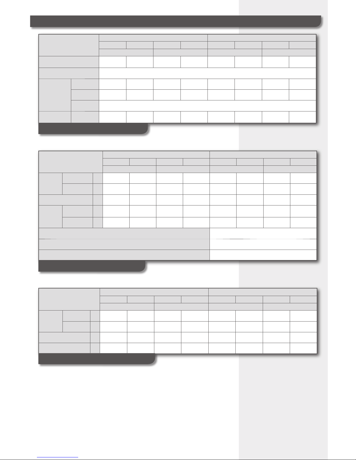
RenoXtra
NATURAL GAS G20 LPG G31
30CA 37C 30CA 37C 30CA 37C 30CA 37C
MAXIMUM MINIMUM MAXIMUM MINIMUM
CH
INPUT Q
NET kW
25.5 30.7 7.14 9.18 26.06 30.7 7.29 9.18
GROSS kW
28.3 34.0 7.92 10.1 28.3 33.3 7.92 9.97
GAS CONSUMPTION m³/h
2.6 3.16 0.74 0.85 1.06 1.25 0.30 0.38
CH
OUTPUT
NON
CONDENSING
kW
24.8 30.0 6.95 9.0 25.0 30.0 7.0 9.0
CONDENSING
kW
27.85 32.6 7.76 9.8 27.85 32.6 7.76 9.8
SEASONAL EFFICIENCY (SEDBUK)
‘A’
NOX CLASSIFICATION
CLASS 5
CENTRAL HEATING SETPOINT TEMPERATURE RANGE
20 - 82˚C
TABLE 4
PERF ORMANCE DATA (C ENTRAL HEATING)
RenoXtra
NATURAL GAS G20 LPG G31
30CA 37C 30CA 37C 30CA 37C 30CA 37C
MAXIMUM MINIMUM MAXIMUM MINIMUM
DHW
INPUT Q
NET kW
30.6 38.0 7.14 9.18 31.3 38.0 7.29 9.18
GROSS kW
34.0 42.1 7.92 10.19 34.0 41.3 7.92 9.97
GAS CONSUMPTION m³/h
3.2 3.92 0.74 0.95 1.28 1.56 0.30 0.34
DHW OUTPUT kW
30.0 37.1 7.0 9.0 30.0 37.1 7.0 9.0
TABLE 5
PERF ORMANCE DATA (D OMESTIC HOT WATER)
RenoXtra
NATURAL GAS G20 LPG G31
30CA 37C 30CA 37C 30CA 37C 30CA 37C
MAXIMUM MINIMUM MAXIMUM MINIMUM
RANGE RATING (kW)
OUTPUT
30.0 37.1 7.0 9.0 30.0 37.1 7.0 9.0
OFFSET (PASCAL)
-3.0 (Minus Three)**
BURNER
CO2(%)
CASE OFF
9.3* 9.5* 8.4** 8.5** 10.2** 10.2** 9.4** 9.2**
CASE ON
9.5* 9.8* 8.6** 8.8** 10.4** 10.5** 9.6** 9.5**
* =
+
0.5 ** = Ref Only
MAXIMUM
GAS RATE
m³/h
3.2 3.92 0.74 0.95 1.28 1.56 0.30 0.34
TABLE 3
PERF ORMANCE DATA
6. TECHNICAL DATA
www.johnsonandstarley.co.uk
6
Page 7
7. DIMENSIONS & POSITIONING
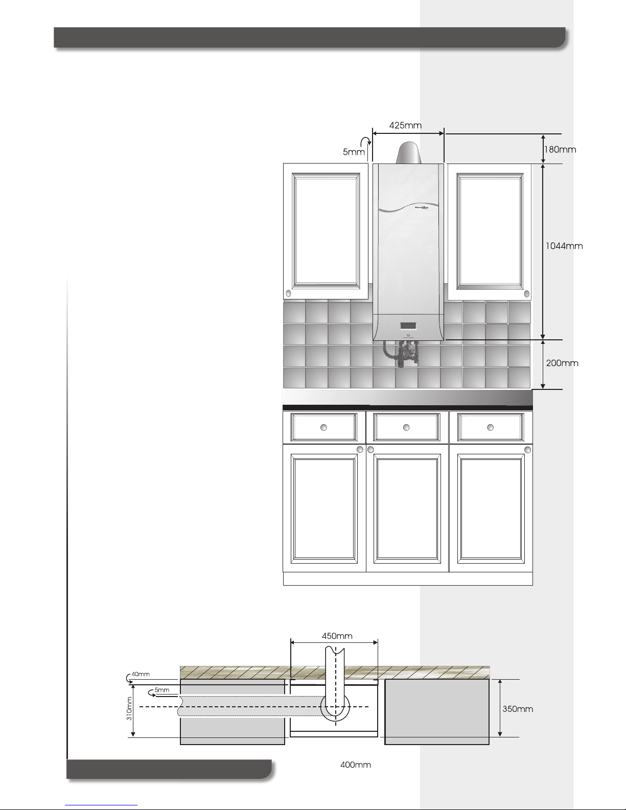
7.1 DIMENSIONS AND CLEARANCES
It is recommended that where the appliance is located in a kitchen, or next to
other combustible materials, a gap of 5mm be left on either side and where
the flue run is through a void in kitchen units, again a minimum gap of 5mm
should be left. For the purpose of servicing, it is also recommended that the
appliance be located with a minimum gap of 200mm above any surface.
7.2 APPLIANCE LOCATION
7.2.1 The appliance is not suitable for
external installation unless it is
protected from the elements by
a suitable enclosure. The enclosure
must provide the required
clearances for installation, servicing
and maintenance as well as the
correct level of ventilation. The
selected position should allow for a
suitable flue system to be installed.
7.2.2 When installed in a timber frame
building guidance should be taken
from the gas industry publication
IGE/UP-7 (Guide for Gas Installations
in Timber Frame Housing).
7.2.3 BS 6798 gives details of the essential
features for a compartment or
cupboard where a gas appliance is
to be installed. An existing cupboard
may require modification.
7.2.4 If the appliance is installed in a room
containing a bath or shower it is
important to locate the electrical
switch in a position where it cannot
be touched by anyone using
the bath or shower. The current IEE
Wiring Regulations (BS 7671) for
England and the electrical provision
of the Building Regulations for
Scotland gives details.
7.2.5 Room ventilation for the appliances
not necessary as the appliance
draws its combustion air from
outside of the building and cupboard
or compartment ventilation is
not necessary providing that
the minimum clearances are
maintained. However, reference
should be made to BS 5440 Pt. 2.
7
Telephone: 01604 762881
FIGU RE 2
MINI MUM CLE ARANCE
KITCHEN FRONT VIEW
*
Note: 200mm dimension is a desired
workable clearance but can be reduced
KITCHEN TOP VIEW
*
**
Note: 400mm dimension is a
desired workable clearance
for servicing
**
Page 8
8. HEATING SYSTEM
IT IS A STATUTORY REQUIREMENT THAT ALL GAS APPLIANCES
ARE INSTALLED BY COMPETENT PERSONS, (i.e. GAS SAFE
REGISTERED INSTALLERS. GAS SAFE MEMBERSHIP ENQUIRIES
- 0800 408 5500 ) IN ACCORDANCE WITH THE GAS SAFETY
(INSTALLATION AND USE) REGULATIONS (CURRENT EDITION).
FAILURE TO COMPLY WITH THESE REGULATIONS MAY LEAD TO
PROSECUTION.
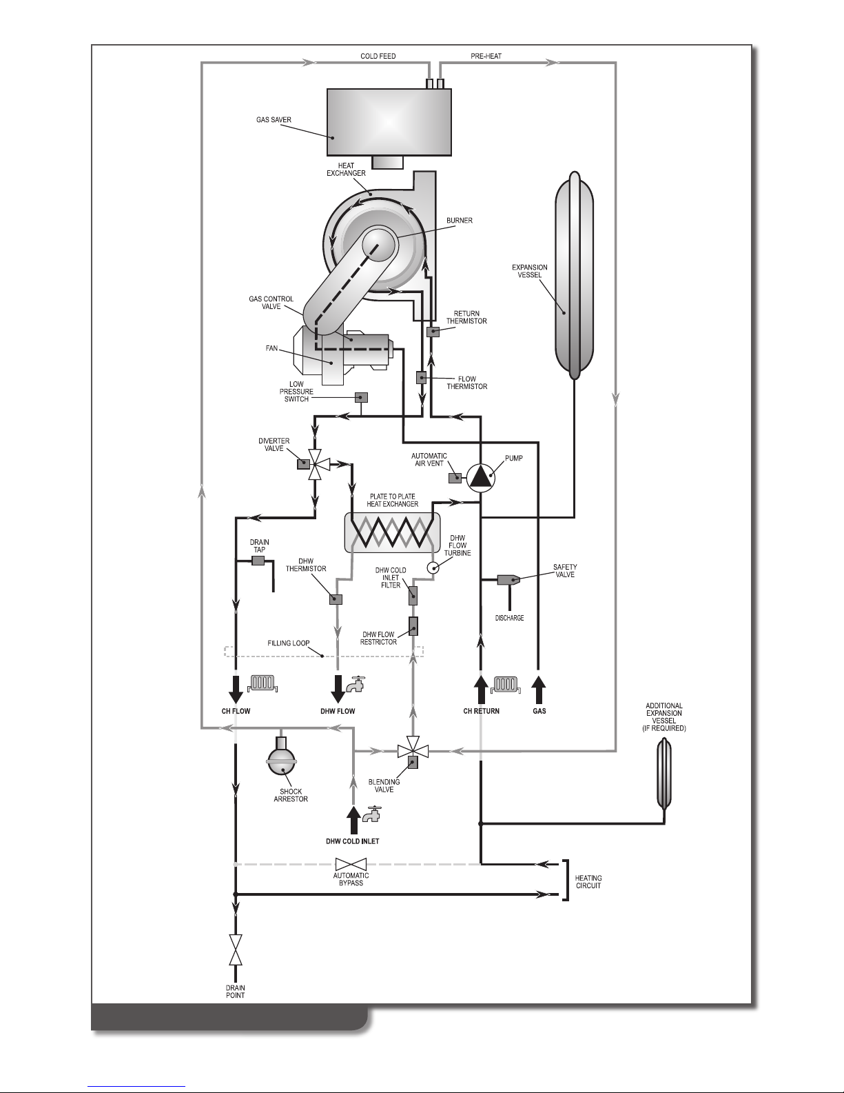
8.1 This appliance incorporates all the necessary components to allow it
to be connected to a sealed central heating system. Figure 3 shows a
typical system incorporating radiators, an automatic by-pass valve and
a drain facility that must be provided at the lowest point in the system to
allow complete drain down. The domestic cold inlet and hot outlet are
also shown and Figure 4 shows the water flow through the boiler. The
installation should be designed to operate with a flow temperature of up to
90˚C.
8.2 EXPANSION VESSEL
The integral expansion vessel is pre-charged to a pressure of between
0.5 and 1.0 bar. This should be checked before the water system is filled.
Details below show the water system volume that is acceptable for this
vessel. If the system water volume is larger then an additional vessel must
be fitted to the system. BS 5449 and BS 6798 give further details regarding
expansion vessel sizing and sealed systems. See Table 6.
8.3 PRESSURE GAUGE
The appliance has two components that monitor pressure. Firstly there is
a mechanical pressure gauge on the plumbing jig, this allows the heating
system to be pre-plumbed and filled with a visual check on the pressure.
The second is an electronic device used by the microprocessor control to
monitor the system pressure and block the heat input, should there be a
lack of pressure.
8.4 LCD DISPL AY
When the electrical supply is connected, the liquid crystal display indicates
the system water pressure. This pressure is also monitored by the
microprocessor controls.
8.5 PRESSURE RELIEF VALVE
The pressure relief valve protects the system from over pressurisation. It is
set to be fully open at 3 bar, however it will start to open at approximately
2.7 bar. It should not be used to flush the system. Using no less than 15 Using no less than 15
mm diameter copper pipe, the discharge pipe must be extended to a
safe place outside the building. The discharge position must be visible,
not onto a public access area or above any window or entrance. The pipe
must have a continuous fall and discharge to a safe place. It is possible
that boiling water and/or steam could be discharged if the safety valve
operates.
www.johnsonandstarley.co.uk
8
EXPANSION VESSEL REQUIREMENTS
Vessel charge and initial system pressure bar 0.5 0.75 1.0 1.5
Total water content of system using 8 litres
(1.45 gals) capacity expansion vessel supplied with
appliance
L 95 84 73 50
For system having a larger capacity multiply the total
system capacity in litres by the factor to obtain the total
minimum expansion vessel capacity required litres
0.0833 0.09 0.109 0.156
TABLE 6
Expa nsion Vessel Req uiremen t
Page 9

8.6 FILLING LOOP
The plumbing jig incorporates a filling loop that temporarily connects
the DHW supply to the CH system. This is used to fill the CH system on
installation and whenever the water pressure has been removed for system
modifications, etc. The filling loop complies with the water supply (water
fittings) regulations 1999 Section G24.1 and G24.2. After filling the system
the hose should be disconnected and stored in a safe place for future use.
A blanking kit (part No: 1000-0020810) is available where it is necessary to
remove the filling loop at one end only.
8.7 PIPEWORK SIZING
In order to keep the noise of the system to a minimum, the velocity of water
should be kept below 1.5 m/s and it should be noted that the appliance
is designed to operate with a temperature differential of 20˚C between
flow and return. The maximum flow rates are 0.3 kg/s (HE30CA) and 0.38
kg/s (HE37C) which, through a 22mm pipe, gives velocities of 1.00 m/s
(HE30CA) and 1.25 m/s (HE37C). Therefore, the recommended minimum
pipe size for the main carcass is 22mm.
8.8 WATER TREATMENT
It is important that the system is flushed thoroughly before the
appliance is left to operate (as recommended in BS 7593) in
order to maintain an efficiently operating heating system. For
replacement installations, the system MUST be flushed with the
old boiler in situ, in order to prevent the Reno becoming a trap
for system debris. Once the system has been flushed, an inhibitor
(suitable for stainless steel heat exchangers) should be added.
Appropriate inhibitors are available, for example Sentinel, Fernox
and Salamader.
Failure to carry out the above procedure will invalidate the
guarantee!
NOTE: Water supplied from a water softener MUST NOT be used
unless a specially formulated corrosion inhibitor is added (see
BS 6798)
8.9 CONTROLS
As a minimum, a time clock and room thermostat must be installed to
control the appliance. Thermostatic radiator valves may be fitted to the
system, however they must not be fitted in the room where the room
thermostat is fitted. There must be at least one radiator installed with lock
shield valves that should not be closed. Further guidance can be obtained
from the Domestic Heating and Hot Water Guide to the building regulations
and GPG 302.
NOTE:
A differential pressure bypass valve MUST be installed to maintain a
minimum flow rate of 18 l/min (RenoXtra 30CA) or 23 l/min (RenoXtra 37C)
(20˚ differential at maximum heat input).
8.10 DOMESTIC HOT WATER SYSTEM REQUIREMENTS
8.10.1 Domestic hot water circuits and their components, must be
in accordance with the relevant standards and water supply
regulations. Further guidance/recommendations can be found in
building regulations G17 to 24 and R17 to 24.
8.10.2 The maximum domestic cold water supply pressure allowable
for this appliance is 5 bar. If the supply pressure exceeds this,
a pressure-reducing valve must be installed in the supply to the
appliance.
8.10.3 If the water to the property is “hard”, more than 200ppm of salts,
then a scale inhibitor should be fitted. Such products are available
from Salamander.
NOTE: The system must not be filled with ‘softened’ water.
The cold water filling position should be before any softening
product.
9
Telephone: 01604 762881
Page 10
www.johnsonandstarley.co.uk
10
FIGU RE 3
WATERFLOW SCHEMATIC DIAG RAM
Page 11
9. FITTING
9.1 TEMPLATE
9.1.1 Using a plumb line (to make sure the unit is square) fix
the template to the wall. Mark the positions of the flue
and the 8 fixing points.
9.1.2 Using a 105 mm core drill make the hole through
the wall. Installations that are made from within the
building only will require a 125 mm diameter hole in
order to fit the flue system.
9.1.3 Using a 7mm bit, drill a total of 4 fixing holes at the top
of the wall plate and a minimum of 2 at the bottom.
Insert the Rawlplugs. Remove the template.
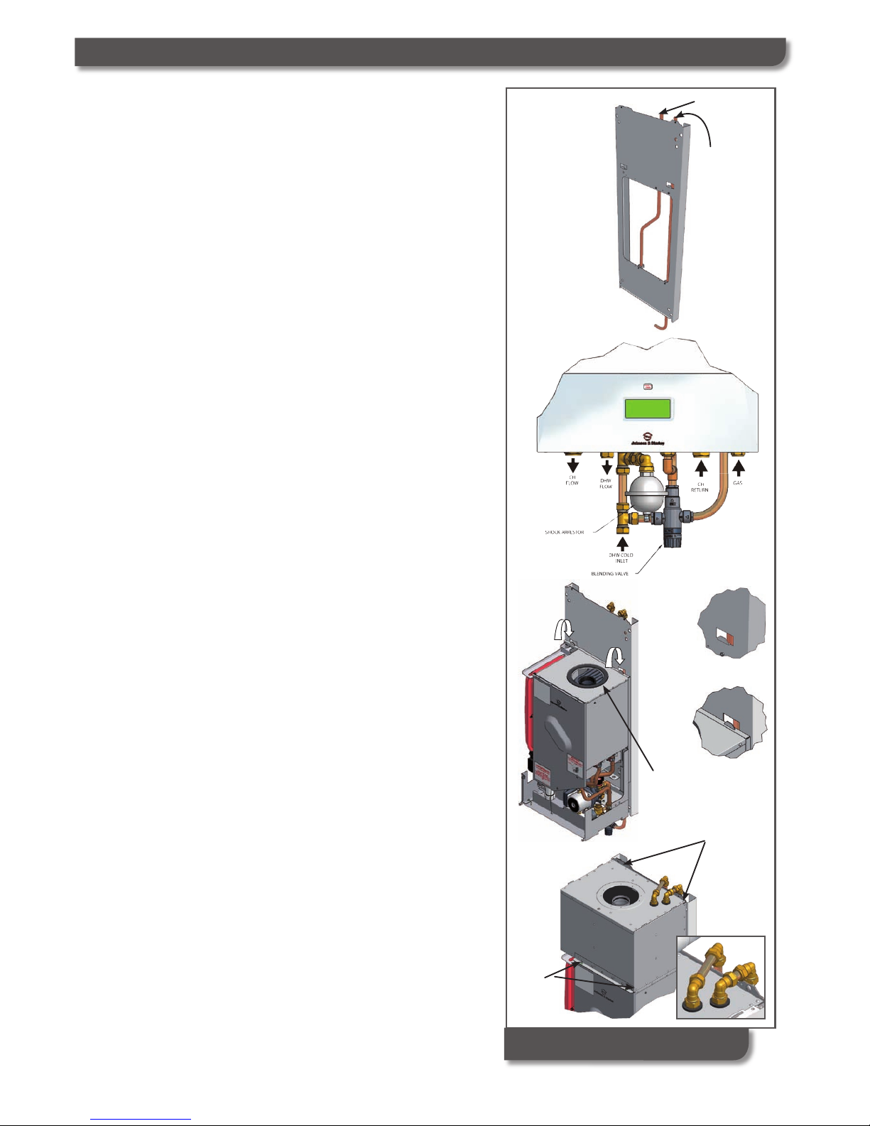
9.2 WALL PLATE ADAPTOR
The wall plate adaptor comes already fitted with the 2 downpipes
attached by clips on the back. Figure 4a
9.2.1 Fix the wall plate to the wall ensuring it is level, with the
screws provided.
9.2.2 Fit the blending valve between the DHW cold inlet
and lower end of pre-heat pipe connect the the outlet
blending valve to the cold water inlet connection on
the RenoXtra. Fit the shock arrestor to the lower end of
the cold feed connection. See Figure 4b.
9.3 FITTING THE APPLIANCE
Caution: this appliance exceeds the recommended weight for
a one-man lift as detailed in the Manual Handling Operations,
1992 Regulations.
It should be noted that this appliance could contain sharp edges and
care MUST be taken when handling.
9.3.1 Lift the appliance onto the wall plate adaptor and
locate the unit on the two lugs on the wall plate. Figure
4c
9.3.2 The boiler then drops into place and needs no further
fixing.
9.3.3 Ensure the gasket is in place and sit the gas saver
unit on top of the appliance. The spigot on the bottom
of the gas saver should slot easily into the heat
exchanger on the appliance. Remove boiler inner
panel to check engaged. These will make a seal once
aligned. Line up the screw holes on the front and
top rear and fix together using the screws and nuts
provided. Figure 4d & 4e
9.3.4 Connect the blending valve outlet to DHW inlet on the
boiler. Figure 4b
9.3.5 Connect the 2 pipes in the wall plate to the gas saver
using 15mm compression elbows. Figure 4g.
9.3.6 Prime gas saver unit by pouring 6 litres of water into
the top of the gas saver before connecting the flue.
9.3.7 Fit side panels, front door and MMI panel.
11
Telephone: 01604 762881
FIGU RE 4
FITT ING THE WALL PLATE & APPL IANCE
a.
b.
e.
c.
d.
Gasket
f.
Top Rear
Fixing
Front
Fixing
Cold Fe ed
Pipe
Hot Fee d
Pipe
g.
Page 12

10. FLUE INSTRUCTIONS
FOR A DETAILED INFORMATION MANUAL ABOUT THE FLUE SYSTEMS AVAILABLE
PLEASE REFER TO OUR RENO, CONCENTRIC & TWIN FLUE INSTALLATION INSTRUCTION
PUBLICATION No. ZZ1191.
10.1 The Reno Combi Boiler is certified as a heating boiler with c orresponding flue syst ems
according to EU Dire ctive 90/396/EEC on ga s-fired devices. These installation instructions
are covered by this certification and are referred to in the design approval test certificate.
10.2 The installation of the boiler and flue system must be in acc ordance with the Gas Safety
(Installation and Us e) Regulations 1998 an d the Building Regulations. If no specific
instructions are giv en, reference should b e made to the relevant codes of practice.
THESE RELEVANT STANDARDS SHOULD BE FOLLOW ED
BS 5440:1 Flues and ventilation for gas appli ances of rated heating input not
exceeding 70kW (ne t) : Flues
BS 5440:2 Flues and ventilation for gas ap pliances of rated heat ing input not
exceeding 70kW (ne t) : Air Supply
Ensure all legislation, regulations and directives mentioned are observed.
10.3 Two types of flue systems are available for the Reno Boiler Range. The standard
concentric flue syst em 60/100 (100mm diame ter) and the concentric twin flue system
80mm which allows fo r longer flue duct len gths to be achieved.
10.4 The air/flue duct operates at very low temperatures therefore no clearance is neces sary
between the air duct and the adjacent serv ices.
10.5 Ensure while installation work is being carried out that no d ebris such as swarf, filings or
fragments of mortar are allowed to remain in the air/flue duct.
10.6 TYPE OF FLUE SYSTEMS
10.6.1 The standard concentric f lue system 60/100 (100mm diameter)
10.6.2 The air/flue duct operate s at very low temperatures therefore no clearance is
necessary between the air duct and the adjacent services.
10.7 FLUE TERMINAL POSITIONS
10.7.1 Th e following informatio n provides the general requirements for siting flue
terminals. As part of the recommendation giv en in B S 1550 Part 1. For IE
recommendations, see t he current issue of I. S. 813 “Domestic Gas Installations.”
Also publication a “G uide for Gas Installat ions in Timb er Framed Housing
DM2” or consult your l ocal gas region, MUST be consulted when installing the
appliance into a timbe r-framed building.
NOTE: Due to the nature of the boiler, water vapour will discharge from the flue. This
should be taken into account when siting the flue
10.7.2 Bo th the horizontal and vertical terminals mus t be positioned on the outside of the
building and the free passage of air must be available at all times. It is not
recommended to positio n the terminal close t o projections especially under a
balcony or near to a d rainpipe.
10.7.3 En sure that combustion p roducts cannot enter t he building where the heater is
installed or near to a ny other building wher e doors or windows may be open.
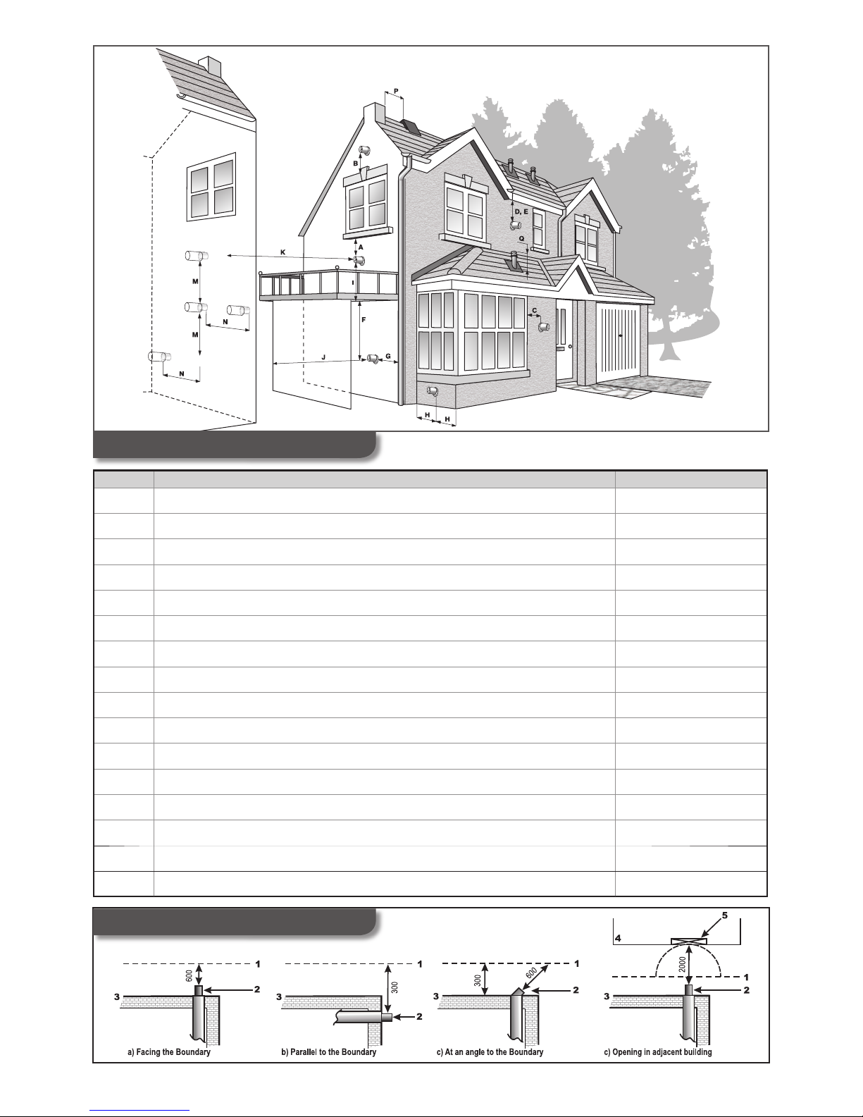
10.7.4 Re commended terminal pos itions for both horizo ntal and vertical flues are shown
and flue components an d installation options are also detailed.
10.7.5 Wh ere the lowest part of the flue terminal is located less than 2 metres above the
ground, a balcony or a bove a flat roof acros s which there is access, the terminal
MUST be fitted with a guard (Part No: 1000-0019710) which is available from
Johnson & Starley. The distance between the guard and the nearest part o f the
terminal must not be l ess than 50 mm.
10.7.6 Th e Flue MUST NOT be ins talled under a car por t.
10.8 PLUME TERMINAL OUTLETS
10.8.1 A flue duct outlet of an appliance should be a t least 600mm from the boundary
line when facing it an d at least 300mm from the boundary line when running
parallel to it. (see F ig 6)
NOTE: When the flow of products is at an angle to t he boundary, the 600mm
dimension may be measured in the direction of the flo w, as long as the terminal
is not less than 300mm from the boundary.
10.8.2 It is recommended the te rminals are not sited within 2 m of an opening in an
adjacent building or w ithin 2m of the bounda ry facing the terminal if the plume
is likely to cause a n uisance to a neighbour, e.g discharging over a walkway or
patio.
www.johnsonandstarley.co.uk
12
Page 13
13
Telephone: 01604 762881
TABLE 7
TERMINAL POSITION MINIMUM DISTANCE
A Directly below an opening, air brick, opening window etc 300mm
B Above an opening, air brick, opening window, etc. 300mm
C Horizontally to an opening, air brick, opening window etc. 300mm
D Below gutters, soil pipes or drain pipes. 75mm
E Below eaves. 200mm
F Below balconies. 200mm
G From a vertical drain pipe or soil pipe. 150mm
H From an internal or external corner. Greater than 450mm protrusion. 300mm
I Above ground, roof or balcony level. 300mm
J From a surface facing the terminal. 600mm
K From a terminal facing the terminal. 1,200mm
M Vertically from a terminal on the same wall. 1,500mm
N Horizontally from a terminal on the same wall. 300mm
Q Above intersection with roof. 530mm
P From a vertical structure on the roof 300mm
R From the terminal to the boundary 300mm
FIGU RE 5
TERM INAL PO SITIONS
FIGU RE 6
PLUME TER MINAL O UTLET D IMENSIO NS
Page 14
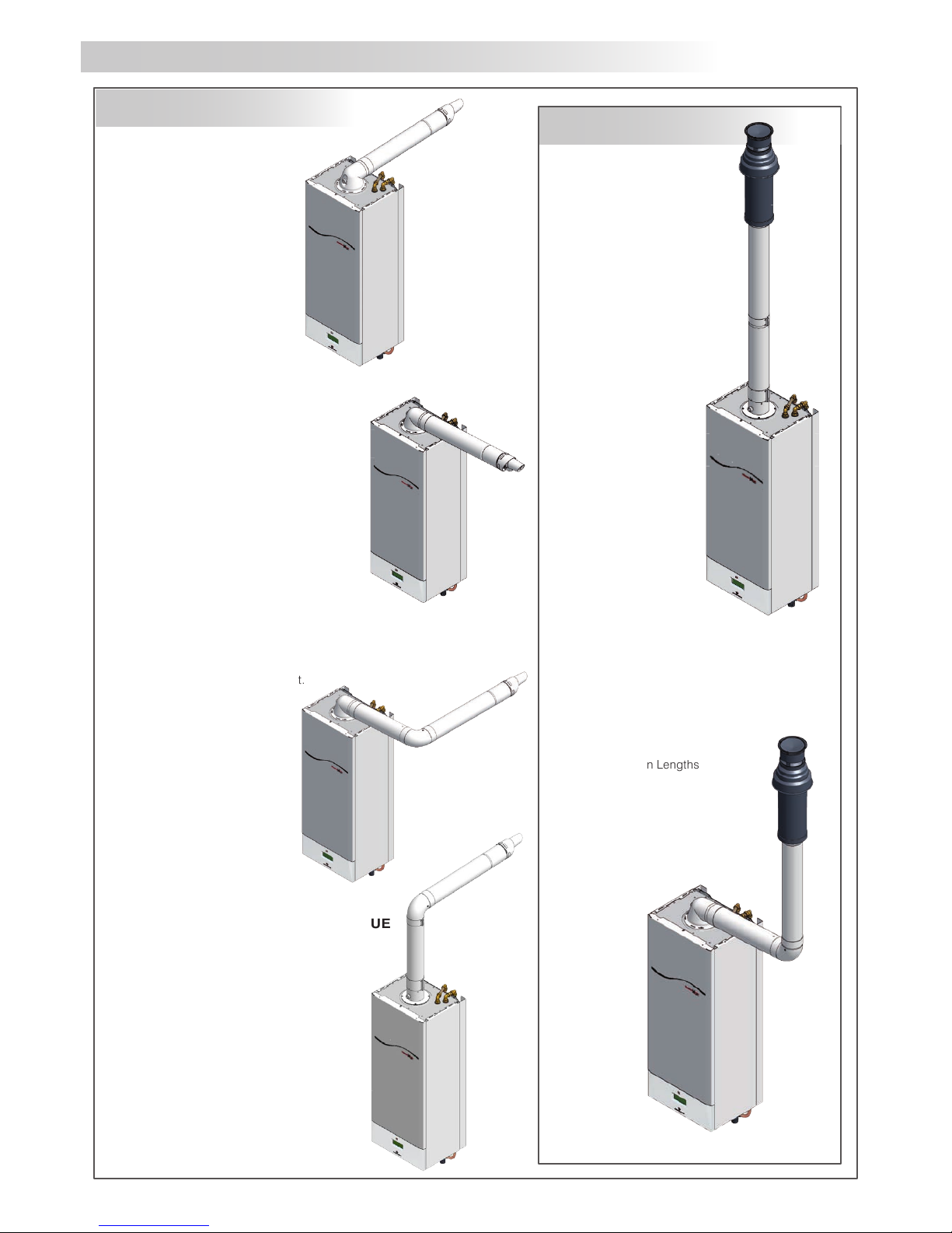
10.8 TYPICAL FLUE CONFIGURATIONS
HORIZONTAL REAR FLUE
Standard flue kit
comprising of:
Turret
Horizontal Terminal
HORIZONTAL SIDE FLUE
Can be fitted to the left or the right.
Standard Flue Kit
Turret
Horizontal Terminal
EXTENDED HORIZONTAL REAR FLUE
Can be fitted to the left or the right.
Vertical Appliance Adaptor
Horizontal Terminal
90˚ Elbow
Required Extension Length
OFFSET EXTENDED HORIZONTAL REAR FLUE
Can be fitted to the left or the right.
Standard Flue Kit +
90˚ Elbow
Required Extension Length
OFFSET VERTICAL FLUE
Can be fitted to the left or the right.
Turret
Vertical Terminal
90˚ Elbow
Required Extension Lengths
VERTICAL FLUE
Vertical Appliance Adaptor
Required Extension Lengths
Vertical Terminal
HORIZONTAL FLUES
www.johnsonandstarley.co.uk
14
Page 15
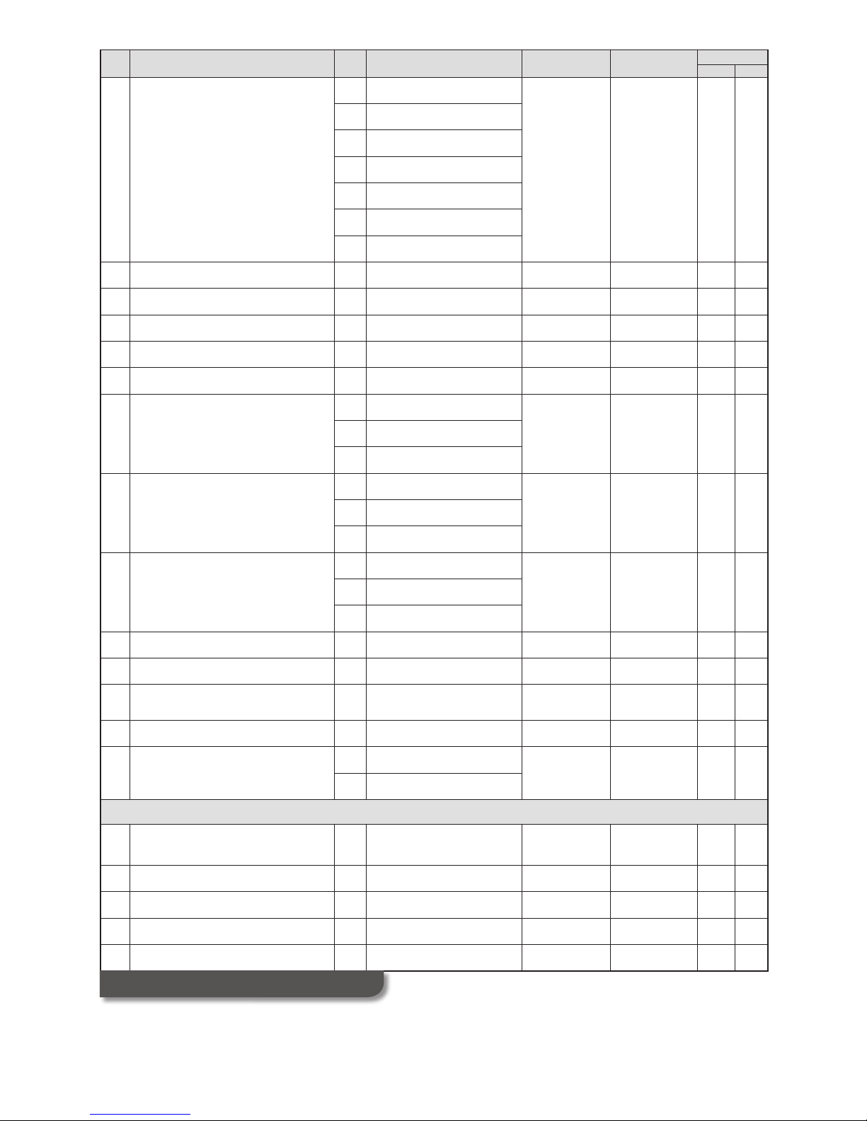
ITEM DESCRIPTION QTY PARTS INCLUDED
APPLICATION
PART No.
PASCAL
30C 37C
1 STANDARD FLUE KIT WHITE
1
Turret
Horizontal 1000-0020070 45 60
1
Appliance Seal
1
60/80 Adaptor
1
Inside Wall Cover Plate
1
Outside Wall Cover Plate
1
100mm Diameter Clamp
1
800mm Horizontal Terminal
1a TURRET WHITE 1
Turret
Horizontal 1000-0020020 40 45
1b HORIZONTAL TERMINAL WHITE 1
800mm Horizontal Terminal
Horizontal 1000-0019830 5 15
2 VERTICAL APPLIANCE ADAPTOR WHITE 1
Adaptor
Vertical 1000-00018990 0 0
3 45˚ ELBOW WHITE 1
Elbow
Horizontal + Vertical
1000-00018980 5 12.5
4* 90˚ ELBOW WHITE 1
Elbow
Horizontal + Vertical
1000-00018980 10 75
5 250mm STRAIGHT EXTENSION WHITE
1 250mm Straight Extension
Horizontal + Vertical
1000-0018960 1.25 41 100mm Diameter Clamp
2 Screws
6 500mm STRAIGHT EXTENSION WHITE
1 500mm Straight Extension
Horizontal + Vertical
1000-0018950 2.5 7.51 100mm Diameter Clamp
2 Screws
7 1000mm STRAIGHT EXTENSION WHITE
1 1000mm Straight Extension
Horizontal + Vertical
1000-0018940 5 151 100mm Diameter Clamp
2 Screws
8 FLAT ROOF WEATHER COLLAR 1 Aluminium Circular Flat Roof Seal Vertical 1000-0020060 n/a n/a
9 PITCHED ROOF COLLAR BLACK 1 Plastic & Lead Pitched Roof Seal Vertical 1000-0020030 n/a n/a
10 RIDGE TERMINAL 1
Condensing Concentric Ridge
Terminal
1000-0021030 5 10
11 WALL FIXING BRACKET 100mm 1 Clamp for 100mm tube
Horizontal + Vertical
1000-0020050 n/a n/a
12 1140mm VERTICAL TERMINAL
1 Vertical Terminal Assembly
Vertical 1000-00018930 5 10
1 Support Bracket
PLUME MANAGEMENT SYSTEM
17
PLUME MANAGEMENT KIT
(BLACK) 60mm
1
Horizontal + Vertical
1000-00200730 21 53
18 1000mm EXTENSION FLUE 60mm 1
Horizontal + Vertical
1000-0020740 3 8
19 90˚ ELBOW BLACK 60mm 1
Horizontal + Vertical
1000-0020680 6 15
20 45˚ ELBOW (BLACK) 60mm 2
Horizontal + Vertical
1000-0020670 3 8
21 WALL FIXING BRACKET 60mm 1
Horizontal + Vertical
100-0020770 n/a n/a
15
Telephone: 01604 762881
TABLE 7
60/1 00 FLUE COMP ONENTS
Page 16
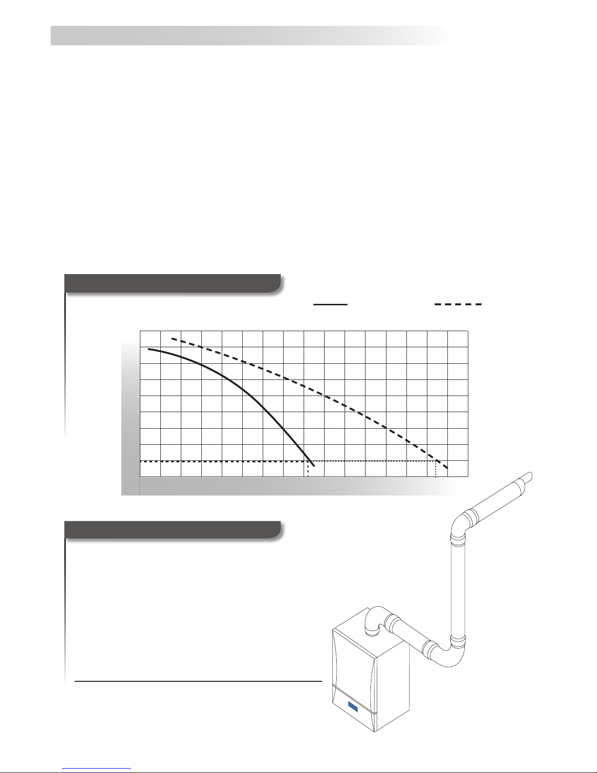
10.9 FLUE REQUIREMENTS & GENERAL INFORMATION
10.9.1 Horizontal and vertical concentric flues (60/100mm diameter) with ba lanced
terminals may be ins talled on all the Reno appliance’s.
10.9.2 If an extended horizontal flue is being used (any flue length longer than the
standard kit) it mus t have a continuous fa ll back towards the appliance of 3°
(52mm) per meter. This ensures that co ndensate runs back int o the appliance
from the flue system for safe discharge vi a the condensate waste pipe.
Reference should be made to Table 7 for relevant part numbers.
10.9.3 The maximum length of flue permissible is calculated by using the co mponent
pressure drop (Examp les are given in Figur e 8 which include the maximum
lengths at 95% of in put.)
10.9.4 The minimu m vertical flue length is 0.7m from the top of the appliance case to
the top of the termi nal.
10.9.5 Longer flu es may be fitted, howe ver the input of the a ppliance will be reduced
accordingly.
10.9.6 Elbows may be fitted within the flue system with a cor responding reduction in
overall flue length based on the component pressure drop.
10.9.7 Reference should be made to Tables 8.
Heat Input (%)
106
104
102
100
99
98
97
96
95
94
10 20 30 40 50 60 70 80 90 100 110 120 130 140 150 160
Flue Pressure Drop (Pascals)
Flue Pressure Drops for the RenoXtra 30CA & RenoXtra 37C
www.johnsonandstarley.co.uk
16
TABLE 8
FLUE PRES SURE DR OPS
FLUE PRES SURE DR OP EX AMPLE
Turret + Horizontal Terminal = 45 Pa
500mm Extension
= 2.5 Pa
90 Elbow
= 10 Pa
100m Extension
= 5 Pa
90 Elbow
= 10 Pa
TOTAL = 72.5 Pa
RENOXTRA 30CA MAXIMUM FLUE RESISTANCE 82Pa RENOXTRA 37C MAXIMUM FLUE RESISTANCE 145Pa
Page 17
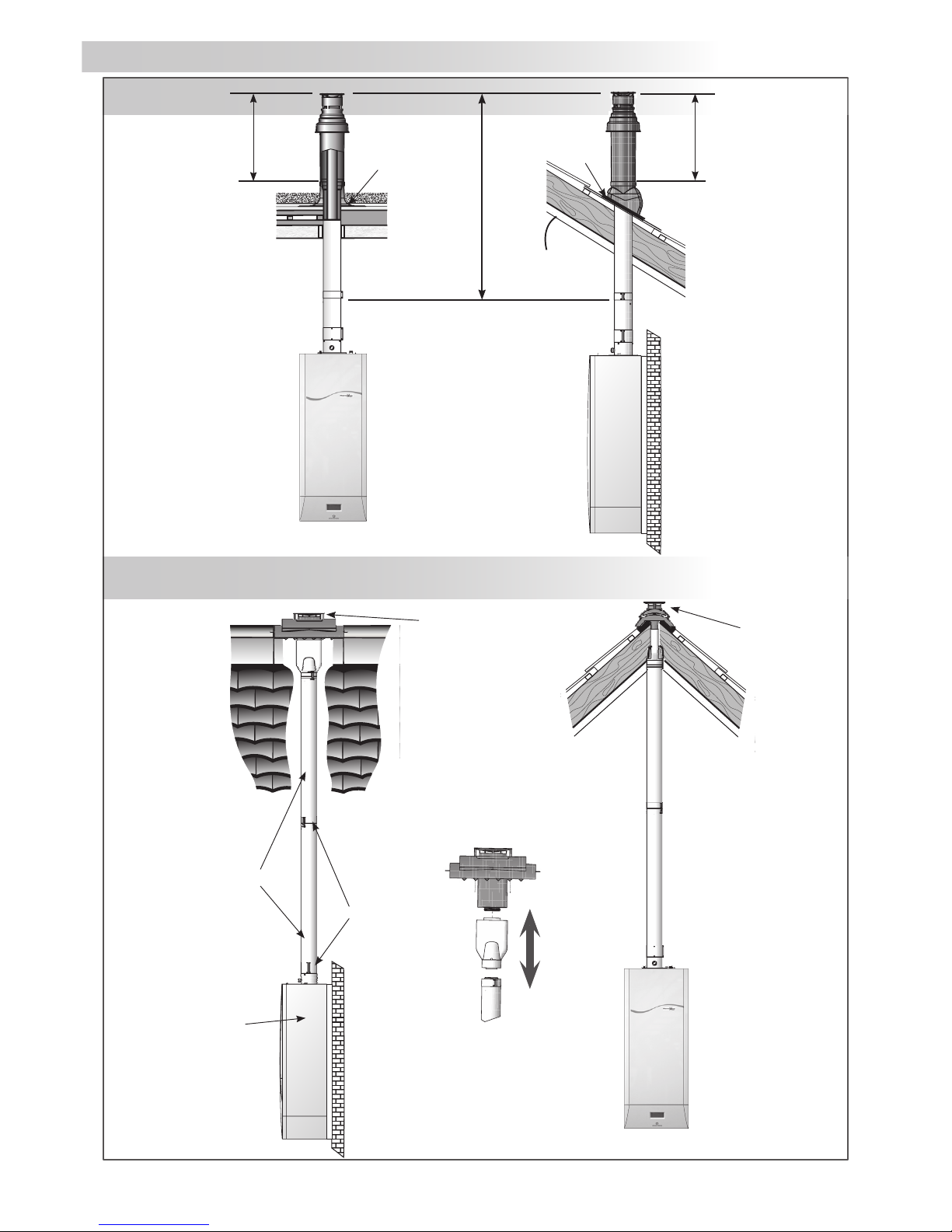
17
Telephone: 01604 762881
500m m
Pitc hed
Roof
Weat her
500m m
1140 mm
Flat Roof
Weat her
Coll ar
20˚ to 50˚
RIDGE TERMINAL
Ridg e
Termina l
Ridg e
Termina l
Clam ps
Flue Extens ions
Verti cal
Appl iance
Adap tor
Adju stable
leng th
10.10 INSTALLATION INSTRUCTION FOR ROOF OUTLETS
PITCHED
ROOF
FLAT ROOF
Page 18
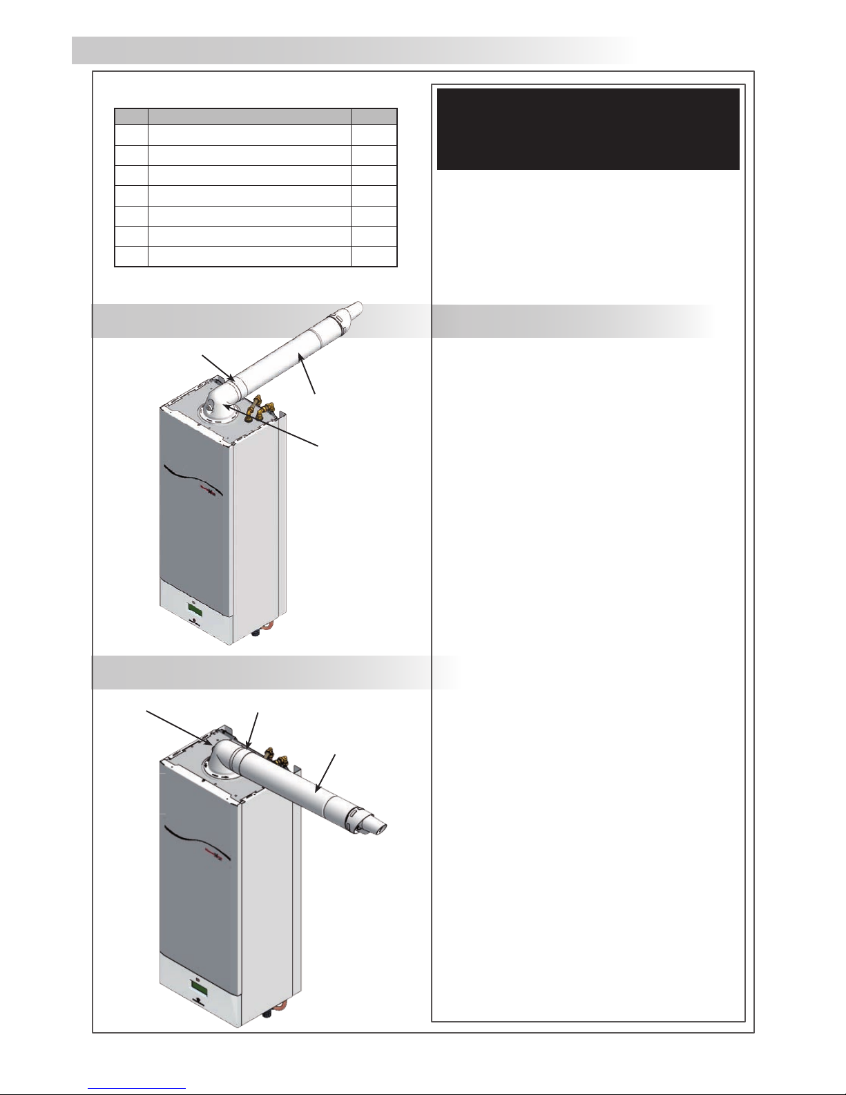
10 .12 I NSTALL ATION O F THE STANDARD F LUE SYST EMS
The stand ard flue kit compr ises of:
ITE M DES CRIP TION QTY
1 Turr et 1
2 Appl iance Sea l 1
3 60/8 0 Adaptor 1
4 EPDM Outside Wall Cover Plate 1
5 Insi de wall c over Pl ate 1
6 100m m Diamete r Clamp 1
7 800m m Horizon tal Termin al 1
Hor izo ntal Terminal
Turret
IMPORTANT NOTE:
Before carrying out this procedure
ensure seal has not been dislodged
from top of heat exchanger.
With the appliance comes a wall template.
(Label Ref: 1000-2217950-3)
1. INSTALLATION INSTRUCTIONS
1.1 Using the template supplied with the boiler,
determine the position of the flue.
1.2 If access is available from outside drill a
105mm diameter hole.
If no access is available refer to section 2.
1.3 Mount the jig and the boiler on the wall
as detailed in the boiler installation
instructions.
1.4 Fit the appliance seal to the underside of
the turret and fix the turret to the top of
the boiler using the 4 screws supplied,
ensuring that the heat exchanger flue seal
and 60/80 adaptor is in place.
1.5 Take a measurement from the outside of
the wall to the edge of the turret dimension
“X” Fig. 1.
1.6 Mark this dimension onto the horizontal
terminal as shown in Fig. 2.
1.7 Cut the flue to the desired length making
sure the ends are square and free from
burrs.
NOTE:
To ease the assembly of the flue
compo nents,
apply suitable silicone lubricant to
the m ale plastic end. (Any other type of lubricant
may c orrode the gasket.)
1.8 Place flue clamp over turret rim.
1.9 From the outside of the building, push the
terminal through the wall and locate the
male plastic end of the terminal into the
female end of the turret.
1.10 Place clamp equally over the turret and
terminal ends and tighten the 2 screws.
1.11 Fit the rubber-finishing ring over the
outside of the flue, pushing it flush to the
wall. The rib on the inside of the ring will
locate in-between the locating pips on the
end of the terminal.
Cl am p
HORIZONTA L REAR FLUE
HORIZONTA L SIDE FLUE
www.johnsonandstarley.co.uk
18
Hor izo ntal Terminal
Turret
Cl am p
Page 19
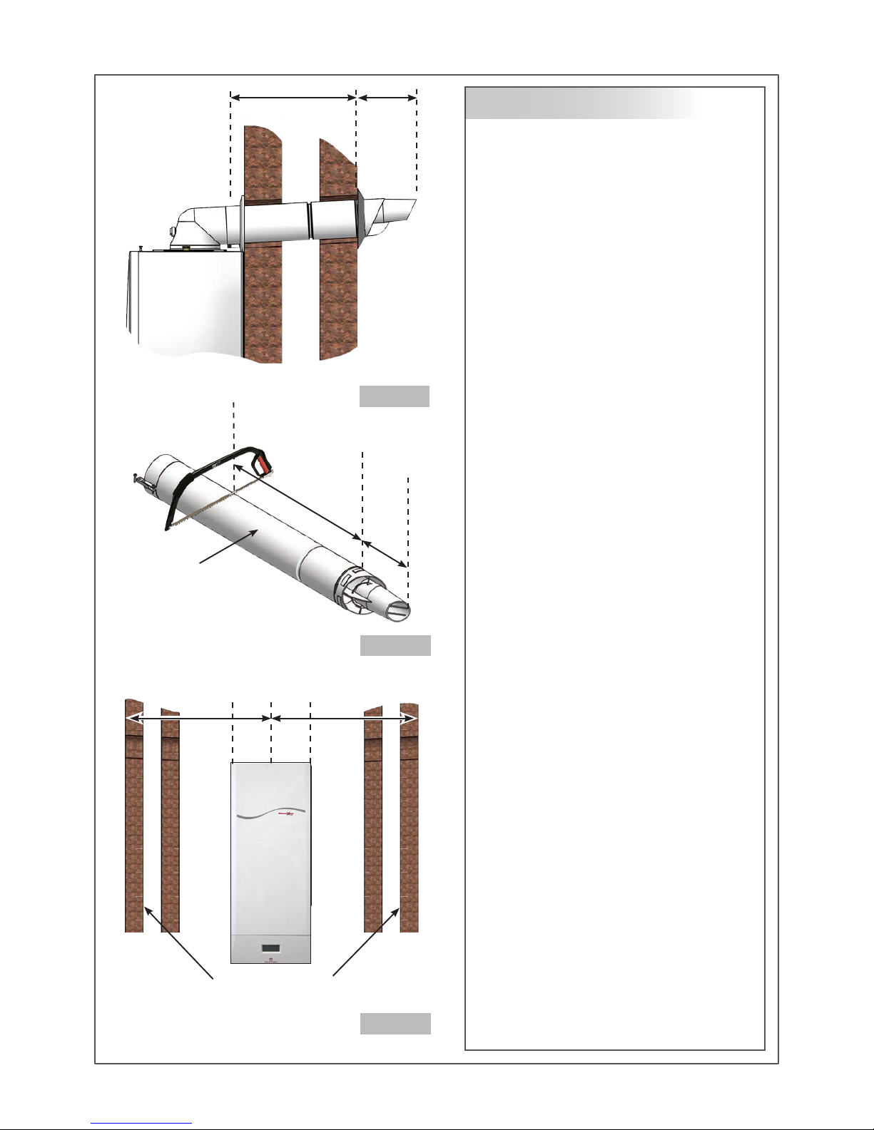
Fig . 1
Fig . 2
X
155 mm
x
155mm
Hor izont al Terminal
2. NO OUTSIDE ACCESS
2.1 If no access is available from outside
the building drill a 125mm diameter
hole.
2.2 Mount the jig and the boiler on
the wall as detailed in the boiler
installation manual.
2.3. a. For a rear flue measure the wall
thickness and add;
40mm for a standard rear flue
90mm for a rear flue if the
standoff bracket is used.
b. For a side flue measure the
distance from the outside wall to
the side of the boiler and add;
Length shown in Fig. 3.
This dimension is known as
dimension “X”.
2.4 Mark this dimension on to the turret
as in Fig. 2.
2.5 Cut the flue to the desired length
making sure the ends are square and
free from burrs.
NOTE:
To ease the assembly of the flue
compo nents,
apply suitable silicone
lubri cant to the male plastic end. (Any other
type of lubricant may corrode the gasket.)
2.6 Fit the rubber-finishing ring over
the outside of the flue. The rib on
the inside of the ring will locate inbetween the locating pips on the end
of the terminal.
2.7 Push the terminal through the hole in
the wall.
2.8 Fit the appliance seal to the
underside of the turret and fix the
turret to the top of the boiler using
the 4 screws supplied, ensuring that
the heat exchanger flue seal and
80/60 reducer is in place.
2.9 Place flue clamp over turret rim
2.10 Pull back the terminal through the
wall locating the male plastic end of
the terminal into the female end of
the turret.
2.11 Place the clamp equally over the
turret and terminal and tighten the 2
screws.
Fig . 3
Dis tance t o outsi de wall
TUR RET FLUE LEN GTH =
Cen tre of boiler to outside wall + XXXmm
19
Telephone: 01604 762881
Page 20
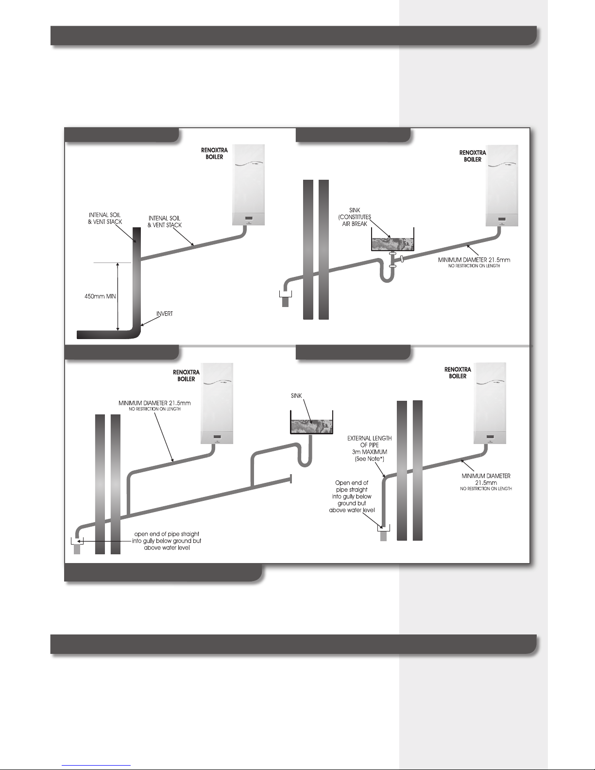
NB the boiler has a built in condense trap and it MUST be noted that
fitting an additional trap to the configurations shown above, may
have an adverse effect on the evacuation of condensate from the
boiler.
12. ELECTRICAL
12.1 Electrical Connections
12.1.1 External wiring must be correctly earthed, polarised and in
accordance with BS 7671 (current edition).
12.1.2 All system components must be an approved type and all electrical
components should have been tested and meet the requirements of
BEAB or equivalent. All the electrical connections to the heating
11. CONDENSATE DRAIN
11.1 The condensate drain utilizes plastic 21.5mm push fit or adhesive overflow
pipes and fittings. It should be piped to drain, preferably within the building,
maintaining a 44mm in 1m fall away from the appliance. If the drain is routed
to outside it should be to a drain or soak away. Protection from freezing in cold
weather conditions is also advisable.
NOTE:
* External runs exceeding 3 metres the discharge pipe should be
increased to 32mm diameter for complete peace of mind.
www.johnsonandstarley.co.uk
20
FIGU RE 7
TYPI CAL CON DENSATE D RAIN AR RANGEME NTS
FIGU RE 7bFIGU RE 78a
FIGU RE 7c FIGURE 7d
Page 21

system must be through a common double pole isolation switched
spur that has a 3mm separation on each pole and has a 3A rated
fuse. It should be used for the heating system only and no other
household components. A fused three pin plug and shuttered outlet
may also be used provided they both comply with BS 1363.
Important: This appliance must be earthed and it must be wired
in accordance with these instructions. In addition, it must have a
permanent electrical supply that is not interrupted by a timing device
or thermostat.
12.1.3 Fit the electrical supply cable as shown using the connection plug
provided. The cable must be at least 0.75 mm², PVC insulated to
BS 6500.
12.1.4 As a minimum, a room thermostat MUST be fitted and therefore
the link between L2 & L1 should be removed and the thermostat
connected between these two connections. If the thermostat has
a neutral connection, this should be used in order to enhance the
temperature control. Programmable thermostats are wired in a
similar way!
All cables entering/leaving the appliance MUST be restrained by
use of the cable clamps!
12.2 Frost Protection
12.2.1 The microprocessor based controls within the appliance monitor the
water temperature in order to protect from freezing. To ensure that
this function is active the main switch on the appliance should be
left on and the gas supply also left on. This does not protect remote
areas of the heating system, which should be protected by other
means (e.g. an independent frost thermostat that is linked back to
the appliance).
12.2.2 If a frost ‘stat is required to protect remote parts of the heating
system, this should be fitted as accordingly.
12.3 Optional System Controls
12.2.1 Opentherm protocol controls are available for outside temperature
compensation and room temperature sensing and can be used to
improve the heating system control. They must be connected to
the correct terminals as described in their own instructions. A room
thermostat MUST NOT be used with these controls.
12.4 Fitting The Case & Control Module
12.4.1 Remove the case components from their packaging and fit the LH
and RH case panels to the appliance. Each panel hooks over the
two lugs at the top of the appliance and screws to the base with the
screws provided.
12.4.2 Remove the controls door from the module panel and offer the
controls module up to the side case panels. The two hinge pins drop
into the two slots on the groupset support.
12.4.3 Fit the support strap (green cord) to the appliance to support the
controls in the horizontal position.
12.4.4 Make the electrical harness connections to the rear of the module,
ensuring that the harness connections are paired with their
respective mates on the control module: X1; X2 etc.
12.4.5 Swing the controls up into their vertical position and secure to the
side case with the two screws provided.
12.4.6 Refit the controls door, fit the front outer case and secure with the
screw in the top of the boiler.
12.5 Electrical Testing
Carry out electrical checks:
• Earth continuity and short circuit of cables
• Polarity of the mains supply
• Insulation resistance to earth.
12.6 Electrical Supply Failure
12.6.1 In the event of electrical voltage supply failure, the appliance will
stop operating but remain in a safe condition.
12.6.2 When the electrical supply is resumed, the appliance will start from
its safe off condition and continue to operate in the normal manner
under the control of the system components. Should the appliance
fail to resume, press the RESET button to allow the safety control to
be reset. Normal operation should then continue.
21
Telephone: 01604 762881
Page 22
13. FUNCTIONAL FLOW DIAGRAM
www.johnsonandstarley.co.uk
22
FIGU RE 9
FUNC TIONAL FLOW CHART
Page 23
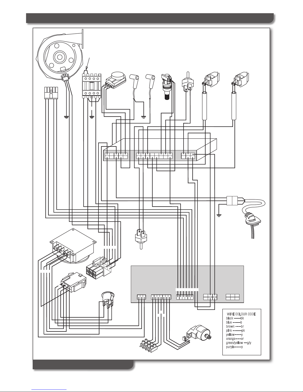
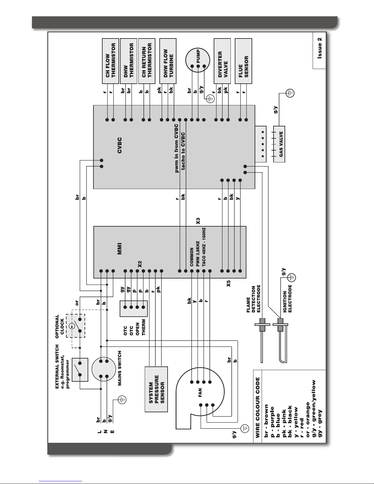
14. WIRING DIAGRAM
23
Telephone: 01604 762881
WIRE COLOUR CODE
black ------bk
blue -------b
brown -----br
pink --------pk
yellow------y
orange-----or
green/yellow ---g/y
purple------p
br
b
r
y
bk
br
pk
br
br
br
b
b
g/y
g/y
br
r
r
b
r
r
b
b
b
or
br
br
b
p
p
r
b
or
b
br
b
b
ybr
b
b
g/ybk
br
or br
b
br
r
r
pk
bk
bk
b
pk
r
L1
L2
N
L3
br
PUMP
CLOCK
(OPTIONAL)
DHW
THERMISTOR
PC
CONNECTIONS
MAINS
SWITCH
FAN
PRESSURE
SENSOR
OPEN
THERM
OTC
DIVERTER
VALVE
MAINS
SUPPLY
230V~50Hz
REMOVE THIS
LINK TO FIT
THERMOSTAT
SPARK
ELECTRODE
FLAME
DETECTION
ELECTRODE
FLUE
THERMISTOR
CH FLOW
THERMISTOR
DHW FLOW
TURBINE
CH RETURN
THERMISTOR
CVBC
gy
gy
g/y
or
brbb
br
b
br
or
r
bk
bk
y
b
r
b
r
br
L
X1
X2
X3
X5 X4
N SL
bk
y
MMI PCB
pk
br
FIGU RE 10
ILLUSTRATED WI RING DI AGRAM
Page 24
15. COMMISSIONING
15.1 With all the pipe connections made, open the cold supply water valve
and the CH flow and return valves at the base of the appliance. Open the
manual vent at the top of the appliance and bleed, close the manual vent
when all the air is removed and ensure that the autovent cap is open.
15.2 Ensure that all isolating valves are open and that the system is
pressurised to the correct level.
15.3 Having tested for gas tightness, purge air from the gas supply and turn
on the gas service cock. Prime gas saver unit by pouring 6 litres of water
into the top of the gas saver before connecting the flue.
15.4 Ensure the domestic cold water system, all system radiators and the
boiler have been bled.
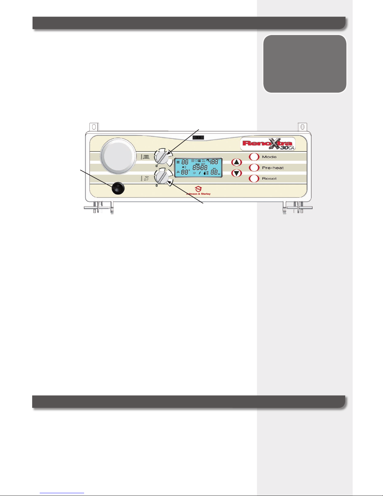
15.5 Turn the CH and DHW controls to minimum, switch on the electricity
supply to the appliance and turn ON the ON/OFF switch on the boiler
control panel.
15.6 The LCD display will become active, whilst the microprocessor control
completes a number of checks and sets the appliance to a standby
position. When the boiler reaches its temp. set point, the anti-cycle
feature introduces a 180 second delay between cycles, indicated by an
hour glass symbol on the display. The display will indicate the system
pressure in the lower RH corner of the LCD panel and a numerical
display in the upper and lower LH side of the LCD panel.
15.7 Check that any external controls are calling for heat, switch the integral
time clock (if fitted) to the ON position and turn the CH temperature knob
clockwise. The set point temperature will be displayed on the LCD
screen, set it to 60˚. The fan will start and the ignition sequence
will take place. The display will indicate the burner is on and a stylised
flame will be displayed when the flame is established.
15.8 If ignition does not take place during the first ignition attempt, there
will be a further 2 attempts. If the burner has still not lit, a fault code
will be displayed and this may be due to air being present in the
gas supply. Pressing the reset button will initiate a second sequence of
ignition attempts.
15.9 When the boiler lights, allow the appliance to operate at low temperature
and vent all the air from the boiler and system. If necessary, re-pressurise
the system to between 1.1 and 1.5 bar.
15.10 Turn OFF the CH by turning the C.H control to the OFF position. Turn the
DHW temperature control to maximum. Open a DHW tap and allow the
water to flow. The appliance will start an ignition sequence and light the
burner. After ignition, the control will monitor the water temperature and
try to maintain the DHW set point.
15.11 When the above checks have been completed, a combustion
performance test (as detailed in the SERVICING section) can be carried
out if required.
16. HANDING OVER
16.1 After commissioning, the installer should hand the appliance over to the
occupier of the house by the following procedure:
16.2 Hand the User Instructions ZZ1312 to the occupier and explain their
responsibilities in respect of current legislation and regulations,
both national and local.
16.3 Explain and demonstrate how to light and shut down the appliance.
16.4 In order to gain the best possible fuel economy in relation to the heating
and hot water requirements of the household, carefully explain the
operation of the appliance and the use/adjustment of all the system
controls.
NOTE
The gas valve is factory
preset and must not be
adjusted. A replacement
valve must only be
supplied by Johnson &
Starley Ltd.
www.johnsonandstarley.co.uk
24
CH Temperat ure Con trol
DHW Tempera ture Co ntrol
Mai n Swi tch
Page 25
16.5 Advise on the precautions required to prevent damage to the appliance;
the system and the building in the event of the appliance being shut
down in very cold weather.
16.6 Explain how to control the temperature of the radiators and domestic
hot water by use of the controls on the appliance.
16.7 Explain how, in the event of a fault, the appliance will display a fault
code, emphasising that if a fault is indicated they should note the fault
code, turn off the appliance and contact a “competent person” which in
normal circumstances would be a GAS SAFE registered engineer.
16.8 Explain and demonstrate the function/operation of time/temperature
controls and thermostatic radiator valves, emphasising the economic
use of the appliance.
16.9 If a programmer has been fitted, hand the user instructions that were
supplied with the programmer to the occupier.
16.10 Point out the water pressure gauge and explain what it indicates and
that if the pressure falls over a period of time when the system is cold,
a water leak should be suspected and that a “competent person”
should be contacted.
16.11 Emphasise the importance of a regular service and that servicing of the
appliance MUST only be carried out by a “competent person” which in
normal circumstances would be a GAS SAFE registered engineer.
16.12 As the installer you may wish to offer a service contract yourself, or
alternatively you may wish to explain to the occupier that they can take
advantage of an extended warranty scheme offered by Johnson &
Starley Ltd.
Reminder: At the time of commissioning, complete all rel-
evant sections of the Benchmark Checklist located on the
inside back pages of this document prior to handing over
the appliance to the occupier.
17. SERVICING
17.1 SERVICING SCHEDULE
To ensure that the appliance gives continued operation that is both safe and
efficient, it is necessary to carry out regular service checks and whilst the
period between servicing will depend on the installation condition and the
demands placed upon the appliance, it is recommended that the appliance be
serviced annually.
NOTE: it is a statutory requirement that ALL work be carried
out by a “competent person” which in normal circumstances
would be a GAS SAFE registered engineer.
17.2 SERVICING SEQUENCE
17.2.1 Light the boiler and carry out a pre-service check, noting any
operational faults.
17.2.2 Check the gas consumption.
17.2.3 Put the appliance in test mode and connect a suitable flue gas
analyser to the sampling point on the top of the boiler or into the flue
terminal if access is possible (optional test).
17.2.4 For correct boiler operation, the ratio of CO to CO2 in the flue gas
should not be greater than 0.008.
17.2.5 Check that the gas input is at least 90% of the nominal.
17.2.6 Clean the main burner.
17.2.7 Clean the heat exchanger.
17.2.8 Check the condition of the combustion chamber insulation. Any
cracked or damaged pieces should be replaced.
17.2.9 Check the condensate trap for blockages. To remove the trap you
must isolate the water. Unscrew the trap at the bottom to clear.
17.2.10 Check that the flue terminal is unobstructed and that the flue system
is sealed correctly.
17.2.11 Check the DHW flow and if reduced, check the DHW filter for
blockage. (Refer to section 20.13)
Note: In order to carry out either servicing or replacement of
components the boiler front panel and sealing panel must be
removed. (Refer to section 20.1.2)
WARNING. Always turn OFF the gas supply at the gas service
cock and switch OFF and disconnect the electricity supply to
the appliance before servicing.
17.2.12 After completing the servicing or exchange of components, always test
for gas tightness and carry out functional checks as described above.
17.2.13 When work is complete, the sealing panel MUST be correctly refitted,
ensuring that a good seal is made.
17.2.14 After servicing, complete the relevant Service Interval Record
section of the Benchmark Checklist located on the inside back
pages of this document.
25
Telephone: 01604 762881
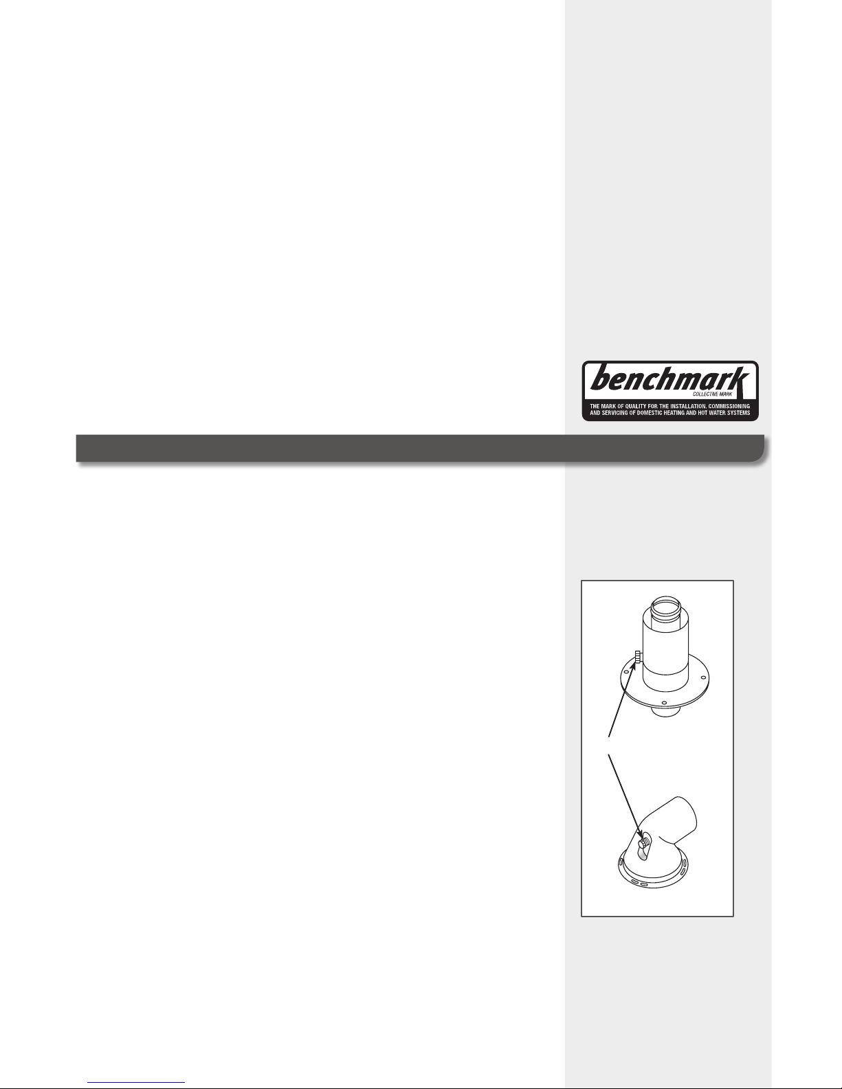
FLUE GAS TEST
POINTS
Page 26
TEST MODE
To put the appliance in test mode, first press and whilst holding it, press the MODE button and hold
both together until the display changes. (Possible 5 second time delay.) If the display shows EHIS press
RESET. and try again. The flow and return temperatures are displayed along with the flame current value and
the fan speed. Whilst in test mode, the appliance overrides all temperature setting and defaults to maximum
rate. Pressing the
and buttons allows you to scroll between maximum and minimum rates, whilst still
overriding all temperature settings*. Press RESET to take the appliance out of test mode. If no changes are
made, the appliance will stay in test mode for 30 minutes.
* On smaller heating systems, running at maximum output MIGHT cause the boiler
to go into lockout and display E3. Allow the heating system to cool and press RESET.
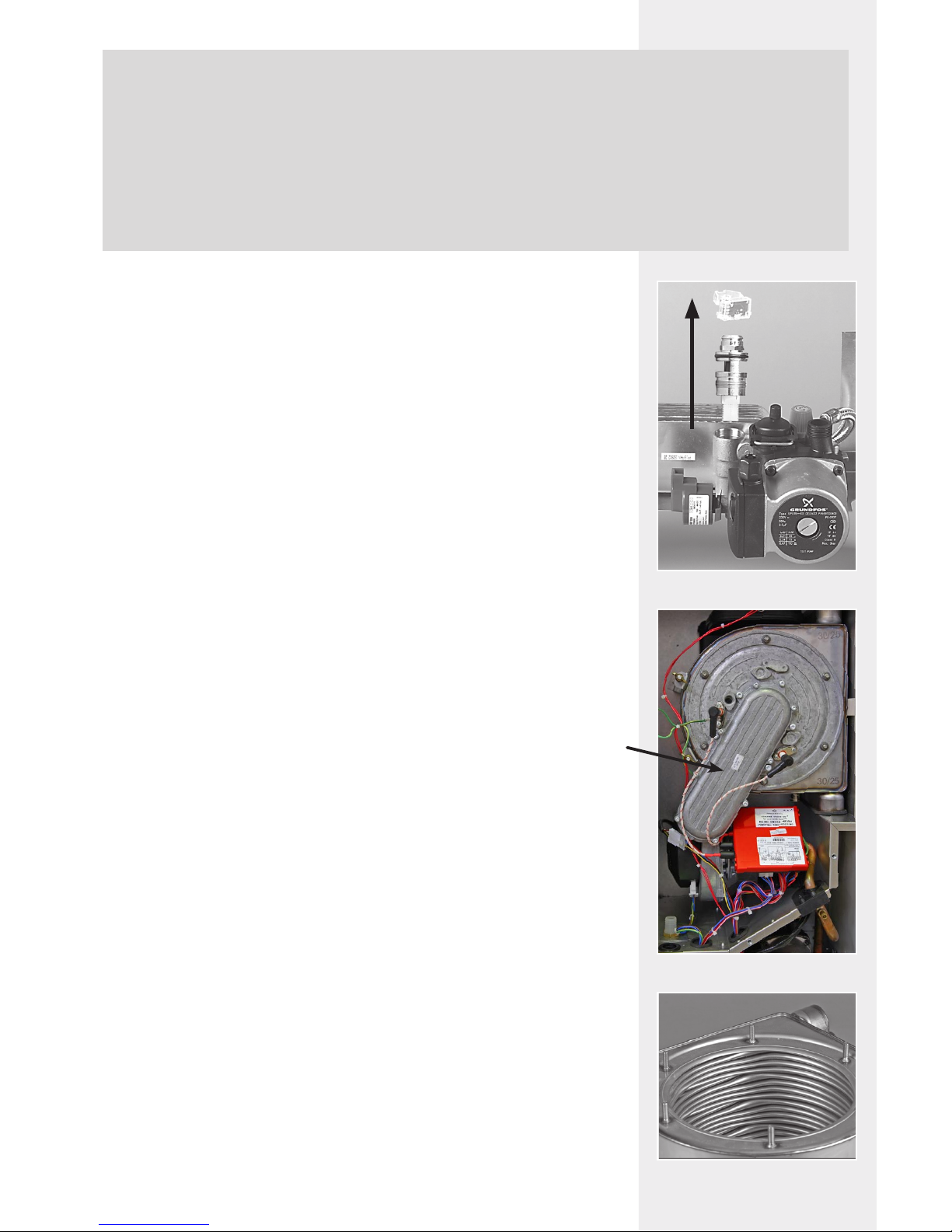
17.2 COLD WATER INLET FILTER
17.2.1 Close the mains inlet valve to the household, open a domestic
hot water tap at the lowest point in the system, allow the pressure
to dissipate and close this tap. Unclip the plastic electronic
component from the top of the turbine, (the wires may be
unplugged if necessary) and pull it off. Remove the grommet from
the sealed chamber above the turbine and unscrew the complete
turbine from the brass housing. The turbine can now be removed
upwards. The complete assembly can now be flushed clean using
water and re-assemble in reverse order, ensuring that all seals are
replaced correctly.
17.2.2 This operation will be made easier by removing the gas manifold
/ fan assembly as described in section 20.121 to gain access to
the cover grommet. Unclip the plastic electronic component from
the top of the turbine, the wires may be unplugged if necessary.
Remove the grommet from the sealed chamber above the turbine.
Unscrew the complete turbine from the brass housing and remove
it upwards through the hole in the sealed chamber. Replace in
reverse order ensuring the grommet is correctly seated.
17.3 GAS/AIR DUCT AND INTERNAL VOLUME OF THE
BURNER
Remove the cover from the gas/air manifold (8 screws) and inspect
the inside of the duct and burner for debris. Clean with a soft brush if
necessary. Inspect the ‘O’ ring seal. Re-assemble the cover ensuring the
seal is fitted correctly.
17.4 COMBUSTION ASSEMBLY COMPLETE
Remove the CVBC (refer to section 20.18) and disconnect the gas pipe
at the top of the isolation valve, which will already have been turned off.
Unscrew the six retaining nuts from the studs that hold the assembly to
the heat exchanger, supporting the assembly as the last one (bottom) is
removed and slowly withdraw the complete assembly, including the gas
inlet pipe and the case seal. As the assembly is withdrawn, disconnect
the two electrical connections from the fan. Inspect and clean the spark
ignition and flame sensing electrode, removing any debris and oxidization
and check the spark gap and position of the spark electrode and the
position of the flame-sensing electrode. Refer to illustrations 20.16 and
20.17 and adjust if necessary. Inspect the two seals and the ceramic pad
on the inside of the mounting plate and clean or replace as necessary.
17.5 COMBUSTION CHAMBER/HEAT EXCHANGER
Inspect the inside of the combustion chamber for debris. If necessary,
brush clean the inside of the tubes with a soft brush. Do not brush the
insulation at the rear, if this part is damaged it will require replacement.
www.johnsonandstarley.co.uk
26
GAS DUCT
Page 27
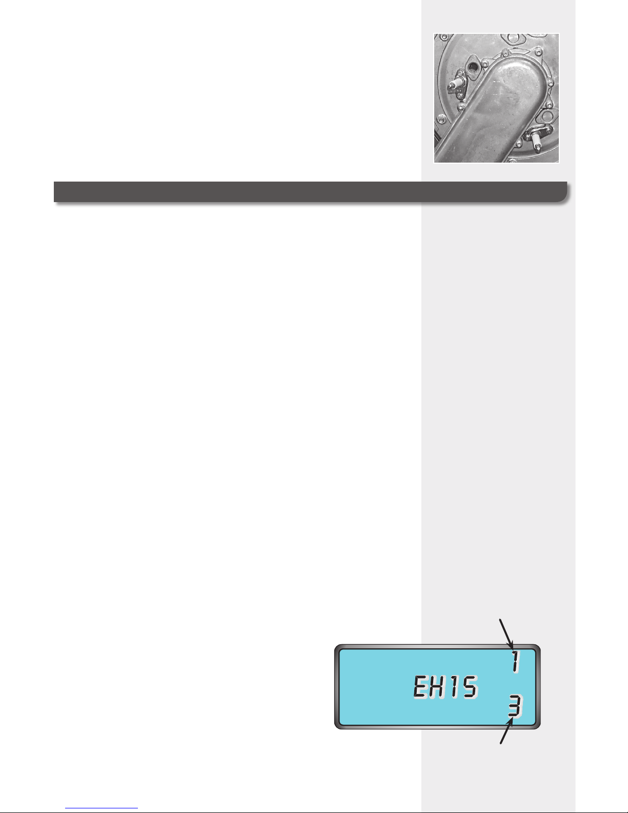
17.6 IGNITION AND DETECTION ELECTRODES
Remove the plug cap from the top and the earth wire from the base of the
spark electrode. Unscrew the two screws that retain the electrode in the
cover plate and remove the assembly. Inspect and clean the electrode,
removing any debris and oxidation. If necessary use an abrasive paper
or cloth. Inspect the gasket and replace if necessary during re-assembly.
Repeat the sequence for the flame detection electrode with the exception
of the earth lead.
18. DEFECT DIAGNOSIS
18.1 CAUTION
18.1.1 Before commencing any mechanical servicing the appliance
should be isolated from the electrical supply and the gas service
cock on the appliance closed. All parts that are removed during
a service operation should be replaced in reverse order, ensuring
correct seals are made and wires are connected correctly. During
the service remove any debris from within the appliance. When
gas-carrying components are serviced the appliance must be tested
for gas tightness after re-assembly. On completion of a service
carry out a full functional test of all appliance components and
ensure system controls are operating correctly.
18.1.2 Remove the upper front case that is retained by a screw in the top of
the appliance.
18.1.3 Remove the control fascia by removing the plastic door, unscrewing
the two screws that hold the control pod in place, rotate downward.
Unplug the wires, slide the hinge pins inwards and remove the
fascia from the appliance.
18.1.4 Remove the sealed door by removing the three screws and lifting
the door clear.
18.1.5 Should a fault occur, the boiler will shut down and the letter E
followed by an error code will be displayed.
18.2 ATTENTION
The flip door at the bottom of the boiler is held in the closed position. To gain
access to the control panel, take hold of the side of the panel at the corners
and pull towards you, allowing the door to drop into the open position. To
close the flip door, lift up the panel and push shut until it clicks into place.
18.3 ERROR HISTORY MODE
18.3.1 The MMI stores the last 8 error codes and these can be viewed by
putting the appliance into error history mode.
18.3.2 To do this, press the MODE button and “E H I S” will be displayed
on the LCD display. The number in the top right hand-corner is the
error index (1 being the most recent) and the number in the bottom
right hand corner is the error code that applies to that index number.
18.3.3 The appliance will stay in error history mode
for a period of 30 seconds and pressing the
and buttons allows you to scroll
through the error codes stored.
18.3.4 Press RESET to manually take the appliance
out of error history mode.
NOTE: all new boilers are shipped with pre-set
error codes stored in the memory.
27
Telephone: 01604 762881
ERROR INDEX NUMBER 1 - 8
ACTUAL ERROR CODE
Page 28

www.johnsonandstarley.co.uk
28
DEFECT DIAGNOSIS
SYMPTOM POSSIBLE CAUSE REMEDY
N/A Boiler will not run No call for heat to boiler control board
Check all external controls (if fitted)
Check settings on time clock
Check settings of boiler controls
N/A No DHW output
No call for DHW to boiler control board.
No or reduced water flow
Check flow from the appliance is correct
Check cold water inlet filter
Check wiring to the flow sensor
Check operation to flow turbine
1 Flame lockout after several attempts Flame not detected
Check gas supply and gas cock
If burner lights, check flame sensor and wiring to control
board
Check operation of gas valve
2 False flame False flame sensed Check wiring to CBVC
5 High water temperature limit
Air in boiler
No water
Vent boiler
Check automatic bypass setting
Check the flow temperature sensor is clipped to flow pipe
Check the pump
Check secondary heat exchanger for blockage
7 High flue gas temperature Reduced water flow
Check insulation at the back of heat exchanger for damage
Check water content and pump operation
8 Flame circuit error Flame sensor lead shorted to earth
Check flame detection leads between sensing probe and
ignition control board
11 Flow/return sensor calibration error
Flow/return sensors not within 5˚ of each other,
within calibration period
Check there is a bypass in the system
Check the flow/return sensors are fitted to the pipes
10-25 Internal control board fault Replace main control board
26 Flame signal lost 5 times in 4 minutes
Flame sensor error
Falling gas pressure
Flue Blockage
Check flame detection lead between sensor and ignition
control board
Check gas supply does pressure fall when boiler fires.
Check the flue system is not blocked
30
Boiler flow temperature sensor short
circuit
Temperature sensor shorted to earth or failed
Check wiring connections for shorting earth
Check sensor resistance
31
Boiler flow temperature sensor open
circuit
Temperature sensor not connected or failed
Check wiring and connections
Check sensor continuity
32 DHW temperature sensor short circuit Temperature sensor shorted to earth or failed
Check wiring connection to shorting to earth
Check sensor resistance
33 DHW temperature sensor open circuit Temperature sensor not connected or failed
Check wiring and connections
Check sensor continuity
34 Low mains voltage
Electrical supply fault to property
Faulty wiring to appliance
Check incoming mains supply and wiring to appliance
35/36 Power supply fault No fault on boiler
Boiler power supply should be checked by a qualified
electrician
37 Low system water pressure Water pressure low or sensor failed
Check system pressure on dial gauge and if correct check
pressure sensor and wiring
Re pressurize the system
39
Opentherm sensor (if fitted) shorted to
earth
Short circuit in wiring between sensor and
control board
Check wiring to sensor
Check the electrical resistance of the sensor
40 High system water pressure
System water pressure too high
Pressure sensor failed
Check cold system pressure
Check expansion tank charge pressure with system pressure
release
Check pressure sensor
43 Boiler temperature sensor short circuit Temperature sensor shorted to earth or failed
Check wiring connections for shorting to earth
Check sensor resistance
44
Boiler return temperature sensor open
circuit
Temperature sensor not connected or failed
Check wiring connection
Check sensor continuity
45 Flue gas temperature sensor short circuit
Short circuit in wiring between sensor and
control board
Check wiring to sensor
Check the electrical resistance of the sensor
46
The flue gas temperature sensor open
circuit
Temperature sensor not connected or failed
Check wiring and connections
Check sensor
99 Communication MMI & CVBC lost
Connection between MMI & CVBC incorrectly
made
Check wiring and connections
Page 29
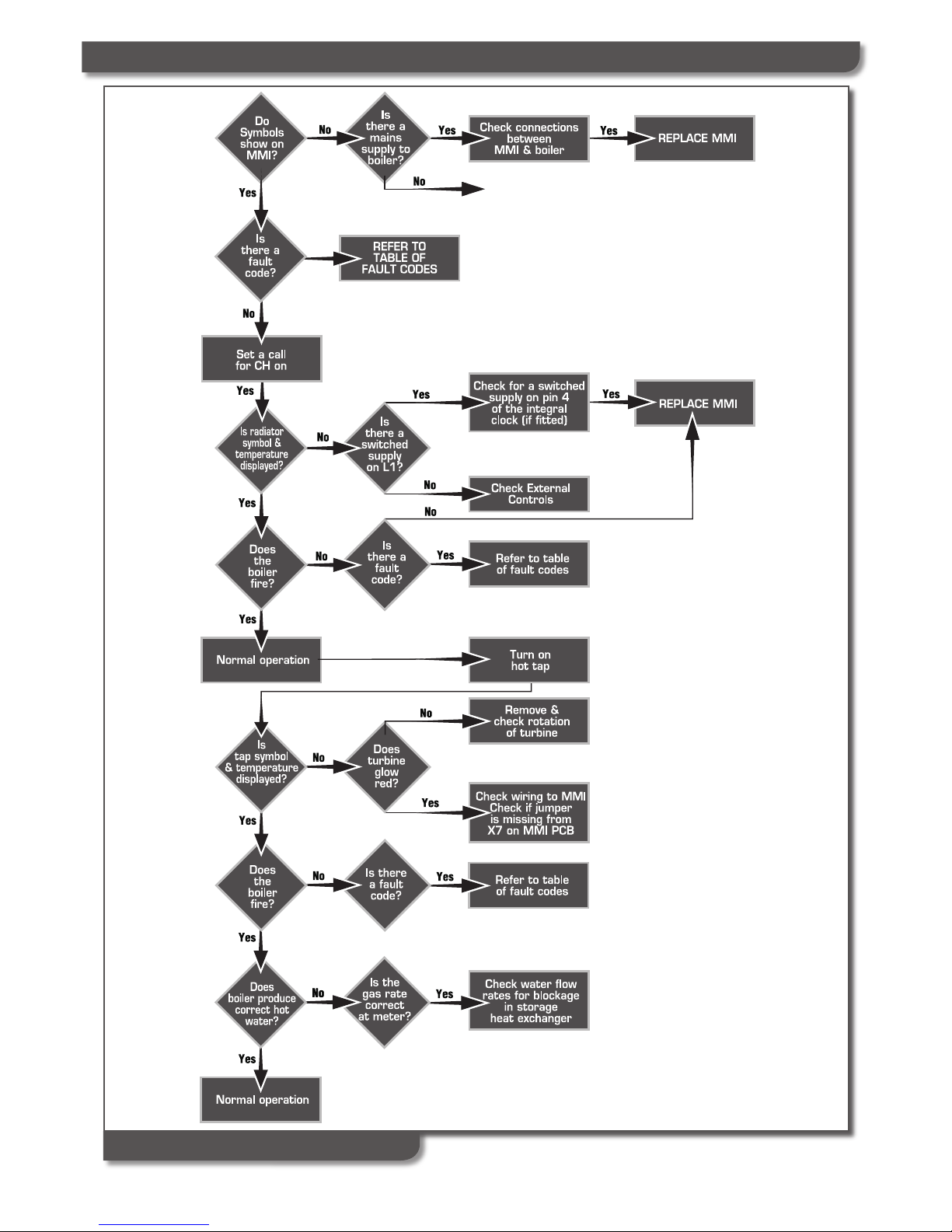
19. FAULT FINDING FLOW CHART
29
Telephone: 01604 762881
FIGU RE 11
FAULT FINDING FLOW CHART
Page 30
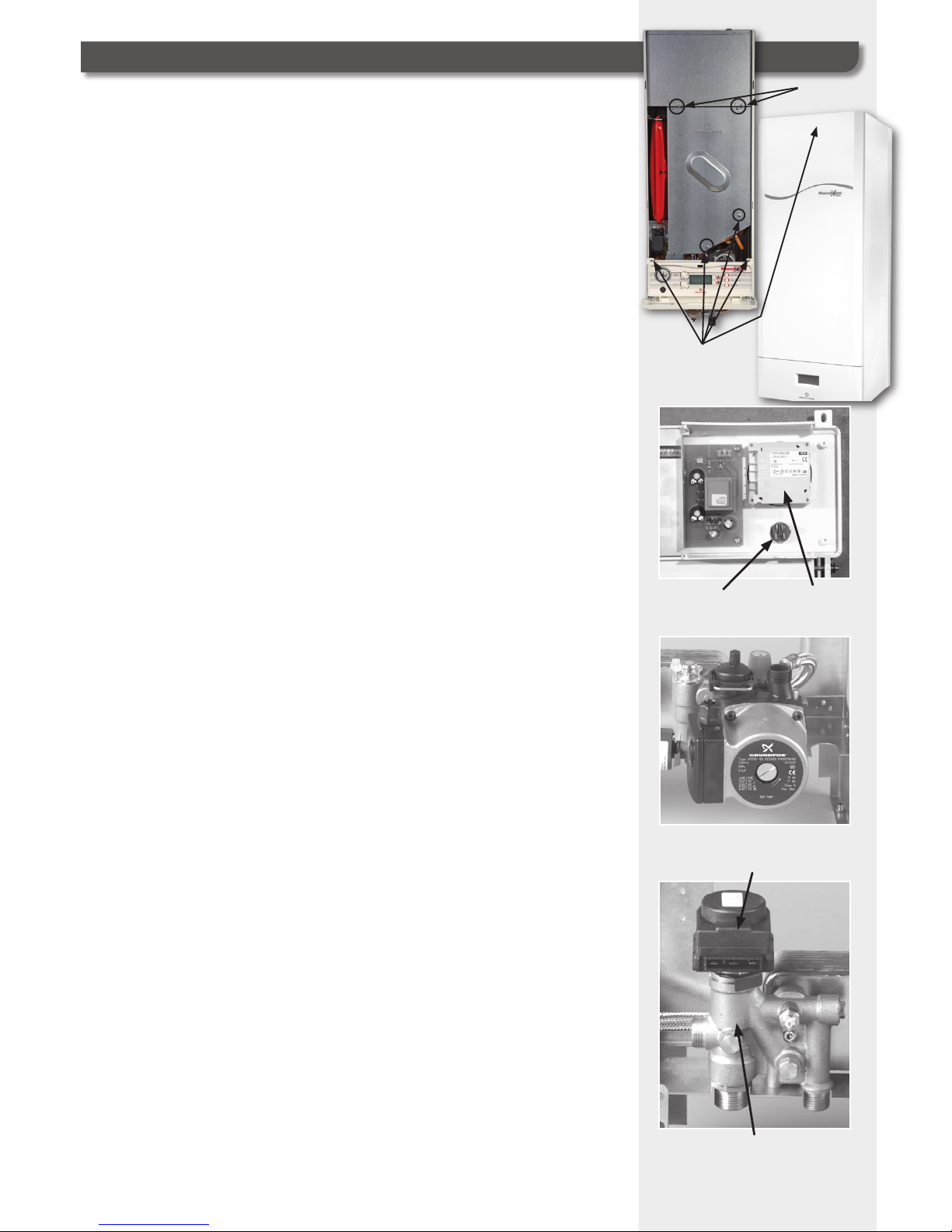
20. PARTS REPL ACEMENT
20.1 INITIAL DISASSEMBLY
20.1.1 Remove the upper front case that is retained by a screw in the top
of the appliance.
20.1.2 Remove the control facia by removing the plastic door unscrewing
the two screws that hold the control module in place, rotate
downward. Unplug the wires, slide the hinge pins inwards and
remove the fascia from the appliance.
20.1.3 Remove the sealed door by removing the six screws and easing
it to the left to disengage it from the LH side of internal casing.
20.2 CONTROL PANEL (COMPLETE)
20.2.1 Because of the complexity and delicate nature of the control PCB, it is
supplied as a complete kit with the plastic facia.
20.2.2 Remove the control panel as described at section 20.1.2 and fit the new
assembly in reverse order.
20.3 MECHANICAL/ELECTRONIC TIMER
Unscrew the metal cover plate from the rear of the control panel. Unscrew the timer
retaining screws and any electrical plug connections. Remove the timer. Replace
with a new component in reverse order
20.4 ELECTRICAL SWITCH
Unscrew the metal cover plate from the rear of the control panel. Unplug the wires
from the switch (NOTING THEIR POSITIONS) and remove the switch. Fit the the new
switch and reconnect the wires ensuring that they are in the correct position.
20.5 PUMP (COMPLETE)
Close the CH flow and return valves, ensuring the drain point on the flow valve is
connected to the appliance side. Drain off the water from within the appliance using
the drain valve. Unplug the electrical connector from the flying lead and unscrew
the lower screw that retains the pump to the appliance. Withdraw the retaining clip
securing the flexible expansion pipe and pull the pipe from the pump. Withdraw the
retaining clip at the rear of the body and remove the pump complete. Replace with
a new component in reverse order.
20.6 DIVERTER VALVE (MOTORISED HEAD)
Carefully pull the three connectors from the electrical connections on the motorised
valve, having made a note of their respective positions. Remove the retaining clip
and withdraw the motorised head upwards from the valve. Replace with a new
component in reverse order.
20.7 DIVERTER VALVE (BODY)
Remove the diverter head as described in section 20.6 and drain the CH and
DHW circuits from the boiler. Disconnect the electrical supply to the DHW sensor,
the CH flow pipe to the radiators and the CH flow pipe from the heat exchanger.
Disconnect the DHW out pipe and remove the 2 x M5 clamp head screws from
the valve body (1 from the centre of the body the second from below). Remove
the complete valve body and unscrew (and retain) the DHW sensor. To replace,
refit the DHW sensor in the new valve and refit the complete valve into the boiler
following the above instructions but in reverse order.
NOTE: Care MUST be taken to ensure that the replacement ‘O’ rings are correctly
seated!
FIX ING
SCR EWS
ELE CTR ICAL
SWI TCH
TIM ER
DIV ERT ER VALVE
BODY
DIV ERT ER VALVE
MOT ORI SED H EAD
FIX ING SCRE WS X
2 p er side
www.johnsonandstarley.co.uk
30
Page 31
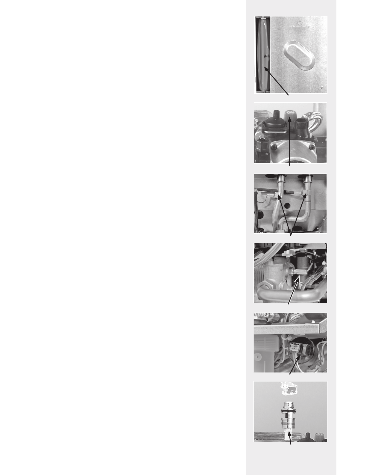
20.8 EXPANSION VESSEL
Close the CH flow and return valves, ensuring the drain point on the flow valve
is connected to the appliance side. Drain off the water from within the appliance
using the drain valve. Remove the LH painted case side. Unscrew the flexible hose
connection from the expansion vessel. Unscrew the upper retaining bracket and
remove the expansion vessel. Replace with a new component in reverse order.
20.9 PRESSURE RELIEF VALVE
Close the CH flow and return valves, ensuring the drain point on the flow valve
is connected to the appliance side. Drain off the water from within the appliance
using the drain valve. Remove the pump as described in section 20.5. Unscrew
the discharge connection and remove the pressure relief valve. Replace with a new
component in reverse order.
20.10 PRIMARY WATER TEMPERATURE SENSORS (2 off)
Unplug the two wires from the temperature sensor to be replaced and unclip the
sensor from the pipe. Replace with a new component in reverse order. Ensure it is
fitted in the same position.
20.11 DOMESTIC HOT WATER TEMPERATURE SENSOR
Close the mains inlet valve to the household, open a domestic hot water tap at the
lowest point in the system and allow the pressure to dissipate. Close this tap again,
carefully remove the two spade connectors from the sensor and unscrew the sensor
from the brass body. Replace with a new component in reverse order, ensuring the
copper washer is fitted correctly.
20.12 PRIMARY WATER PRESSURE SENSOR
Close the CH flow and return valves, ensuring the drain point on the flow valve
is connected to the appliance side. Drain off the water from within the appliance
using the drain valve. Unplug the electrical plug connection. Withdraw the retaining
clip forwards and remove the pressure sensor. Replace with a new component in
reverse order.
20.13 DOMESTIC COLD WATER FLOW SENSOR (TURBINE)
20.13.1 Close the mains inlet valve to the household, open a domestic hot water
tap at the lowest point in the system and allow the pressure to dissipate.
Close this tap again.
20.13.2 This operation will be made easier by removing the gas manifold / fan
assembly as described in section 20.21 to gain access to the cover
grommet. Unclip the plastic electronic component from the top of the
turbine, the wires may be unplugged if necessary. Remove the grommet
from the sealed chamber above the turbine. Unscrew the complete
turbine from the brass housing and remove it upwards through the hole
in the sealed chamber. Replace in reverse order ensuring the grommet is
correctly seated.
EXPAN SION VESSE L
31
Telephone: 01604 762881
PRE SSURE RELIEF VALVE
TEM PER ATURE SENSO RS
DHW TE MPERAT URE S ENS ORS
TEM PER ATURE SENSO R
DCW TE MPERAT URE S ENS OR
Page 32
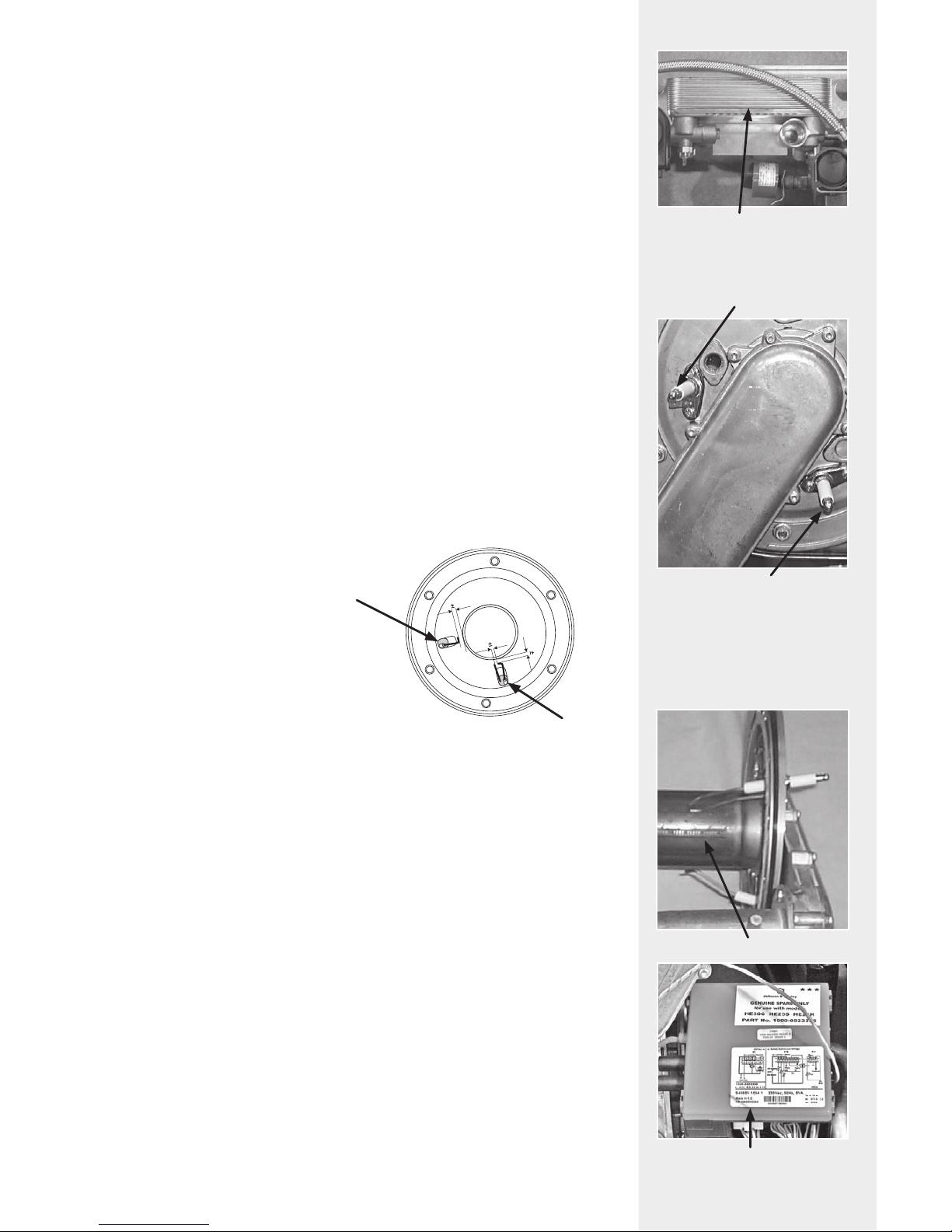
20.14 PLATE HEAT EXCHANGER
Close the mains inlet valve to the household, open a domestic hot water tap at the
lowest point in the system and allow the pressure to dissipate. Close this tap again.
Close the CH flow and return valves, ensuring the drain point on the flow valve
is connected to the appliance side. Drain off the water from within the appliance
using the drain valve. Unscrew the two retaining screws and remove the plate heat
exchanger. Replace with a new component in reverse order.
20.15 IGNITION ELECTRODE
Remove the plug cap and the earth wire from the electrode. Remove the two
retaining screws and withdraw the electrode. Replace with a new unit, ensuring that
the gasket is replaced with a new one, or that the existing gasket reused if it is in
good condition.
20.16 FLAME DETECTION ELECTRODE
Remove the plug cap from the electrode. Remove the two retaining screws and
withdraw the electrode. Replace with a new unit, ensuring the gasket is replaced
with a new one, or the existing gasket reused if it is in good condition.
IMPORTANT:- CLEARANCES
When either the
ignition or flame
detection electrodes have been
serviced/replaced
you MUST set
the clearances as
shown.
20.17 BURNER
20.19.1 Unscrew the gas joint at the top of the gas cock. Unscrew the fan and
gas/air manifold assembly (3 screws) from the heat exchanger. Unplug
the multi pin plug connections from the top of the control and the fan.
Remove the assembly.
20.19.2 Remove the assembly to allow the burner to be withdrawn from the heat
exchanger assembly. Replace with a new component in reverse order.
Ensure the rotational position of the burner is correct (indicated by a
notch) Replace with a new component in reverse order ensuring that the
grommet sealing the casing is correctly positioned.
20.18 MAIN IGNITION/CONTROL PCB (CVBC GREY/RED
HOUSING ON GAS VALVE)
Unplug the multi pin plug connections from the top of the control and remove the
spark detection wires. Unscrew the single retaining screw and slide the housing
off the gas valve electrical connections. Replace with a new component in reverse
order.
NOTE: STARS
www.johnsonandstarley.co.uk
32
HEAT EX CHA NGER
IGN ITI ON EL ECTRODE
FLA ME DETEC TIO N
ELE CTR ODE
BUR NER
CVB C
IGN ITI ON
ELE CTR ODE
5.5
1.0
5.5
1.0
4.5
0.5
FLA ME
DET ECT ION
ELE CTR ODE
Page 33
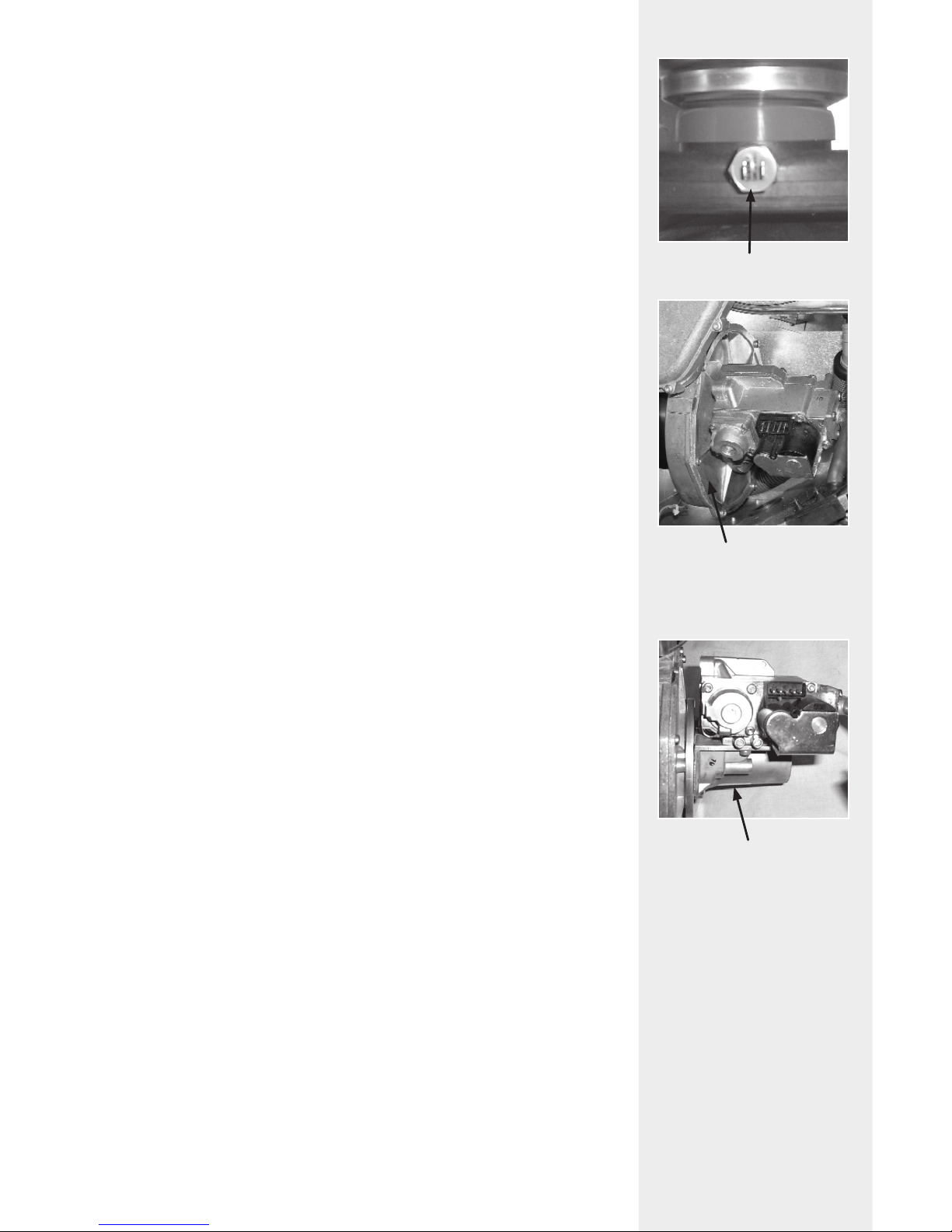
20.19 FLUE TEMPERATURE SENSOR
Carefully remove the two spade connectors from the sensor and unscrew the sensor
from the plastic flue hood. Replace with a new component in reverse order, taking
care not to over tighten!
20.20 FAN
Unscrew the gas joint at the top of the gas cock and remove the CVBC (red box)
from the gas valve. Unscrew the fan and gas/air manifold assembly (3 screws)
from the heat exchanger. Unplug the multi pin plug connections from the top of
the control and the fan. Remove the assembly. Replace with a new component in
reverse order.
20.21 GAS VALVE & VENTURI ASSEMBLY
NOTE: the gas valve is factory preset and must not be adjusted. A replacement
valve must only be supplied by Johnson & Starley Ltd.
20.21.1 Remove the complete fan assembly as shown at paragraph 20.20 and
remove the 4 fixing screws holding the gas feed flange on the gas valve.
Remove the 2 fixing screws securing the venturi (and gas valve) to the fan
and remove the assembly from the fan carefully removing the gasket.
20.21.2 Replace with a new component in reverse order, ensuring that all seals
are in good condition and correctly positioned. Check the gas rate and
combustion as described in section 5 Servicing Instructions.
33
Telephone: 01604 762881
FLUE TEMP ERATUR E SENSOR
FAN
GAS VALVE & VENT URI
ASS EMBLY
Page 34
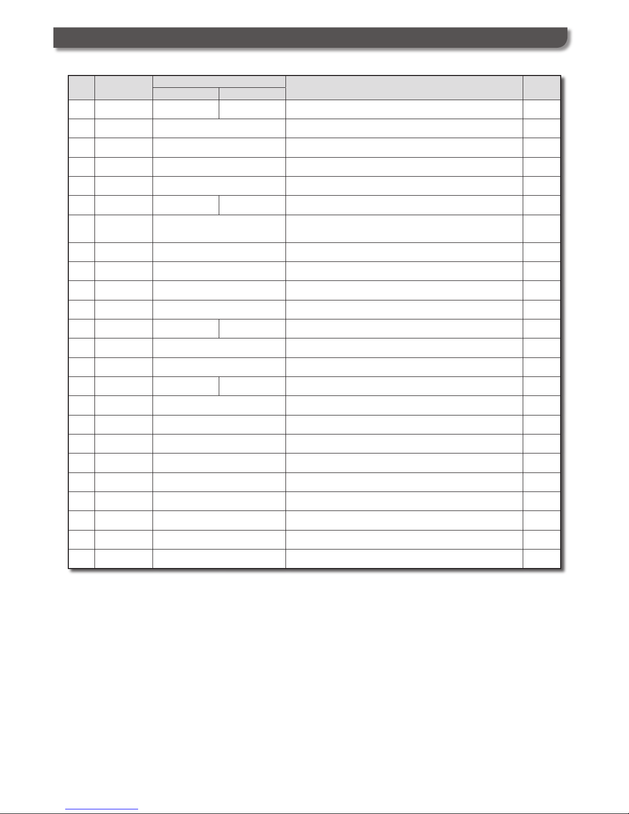
14. LIST OF SPARES
REFER TO THE EXPLODED DIAGRAM
www.johnsonandstarley.co.uk
34
ITEM G.C. No.
PART No.
DESCRIPTION QTY
RENOXTRA 30CA RENOXTRA 37C
1 R300-0501005 R380-0501005 Control Panel Assembly 1
2 H23-609 1000-0301485 Pump 1
3 H23-627 1000-0301615 Diverter Valve (Motorised Head) 1
5 H23-610 1000-0019005 Expansion Vessel (with washer) 1
6 H23-613 1000-0522595 Water Temperature Sensors 2
7 H23-630 1000-0301535 1000-0301645 Plate Heat Exchanger (with ‘O’ rings and fixing screws) 1
8 H23-631 1000-0301625
Domestic Hot Water Flow Sensor
(Turbine, flow resistor, filter & hall effect sensor)
1
9 1000-0020325 CH Pressure Sensor, clip & ‘O’ ring 1
10 H23-623 1000-0522635 Fan, Gasket & Fixing Screws 1
11 H23-624 1000-0709635 Gas Valve, Venturi Assembly 1
12 H23-622 1000-0522645 Flue Temperature Sensor 1
13 R300-0230005 R380-0176005 Heat Exchanger Assembly 1
14 1000-0522685 Ignition Lead 1
15 1000-0522695 Isolation Lead 1
16 1000-0523395 1000-0523405 Main Ignition/Control (CVBC) 1
17 1000-2501425 Seal 1
18 R300-0245005 Gas Saver Box 1
19 1000-0021745 Trap Assembly 1
20 1000-0710205 Female Elbow 15mm - ½ bsp 1
21 1000-0021715 Blending Valve 1
22 1000-0020705 Shock Arrestor (0.16 ltr) 1
24 R300-0243005 Bottom Cover 1
24 R300-0180005 Support Plate Assembly 1
23 1000-0021735 Condensate Drain 1
Page 35

15. EXPLODED DIAGRAM
35
Telephone: 01604 762881
Page 36
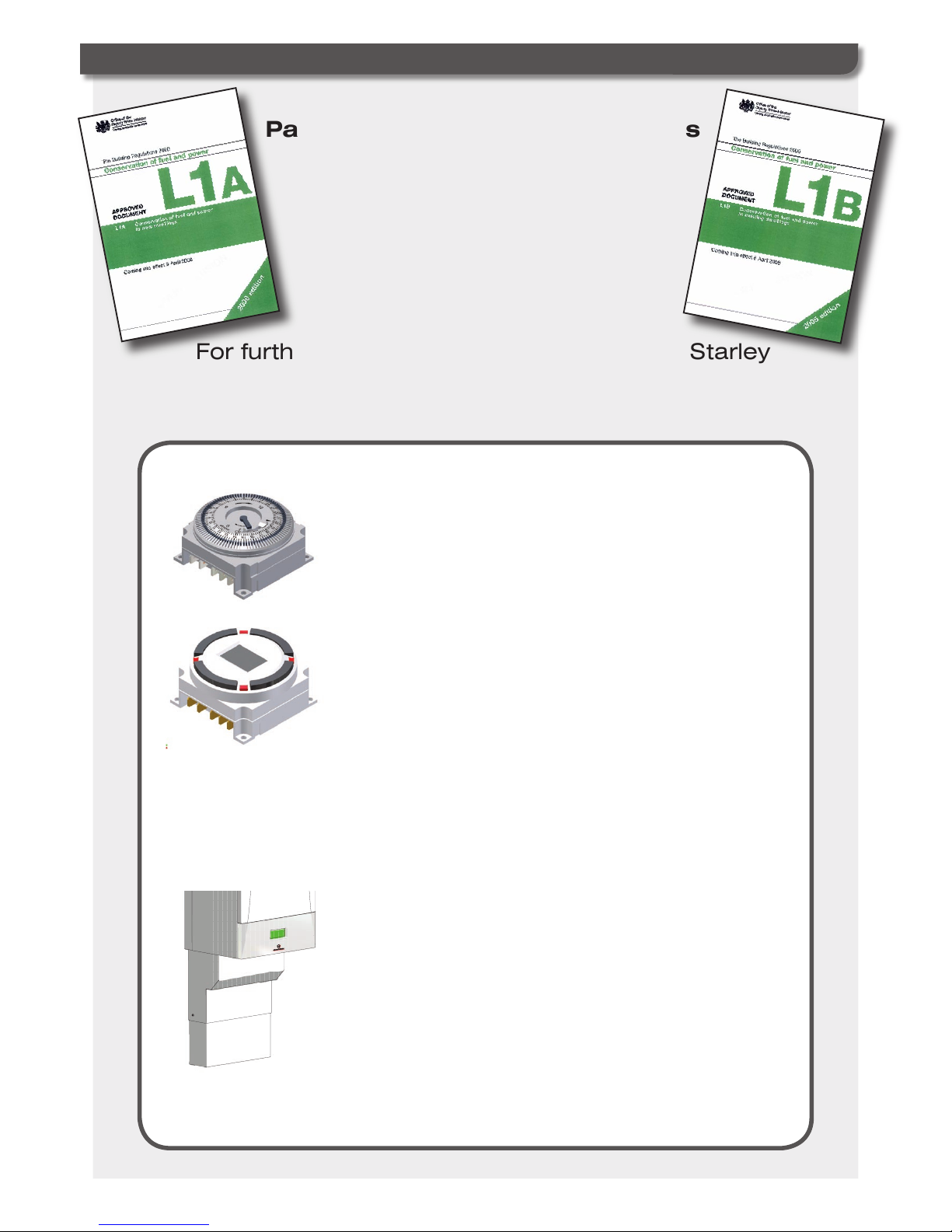
Fully complies with
Part L of the Building Regulations
by following the guidance in the
British Standard BS 5864
and the
Heating Compliance Guide
For further information contact Johnson & Starley
on Telephone 01604 762881
ADDITIONAL KITS AVAILABLE
Mechanical Timer
Part No. MTK 1
Digital Timer
Part No. MTK 2
A single channel electro/mechanical or digital timing device can be
fitted to control the heating periods. Wiring terminals are provided
that may be used to connect a room thermostat.
Opentherm Kit
Part No. 1000-0019720
An opentherm kit is available should an outside temperature
compensation system be required.
Pipe Cover Kit
Part No. PCK 2
This kit can be used to hide open pipe work showing from the bottom
of the boiler.
www.johnsonandstarley.co.uk
36
18. IMPORTANT INFORMATION
Page 37
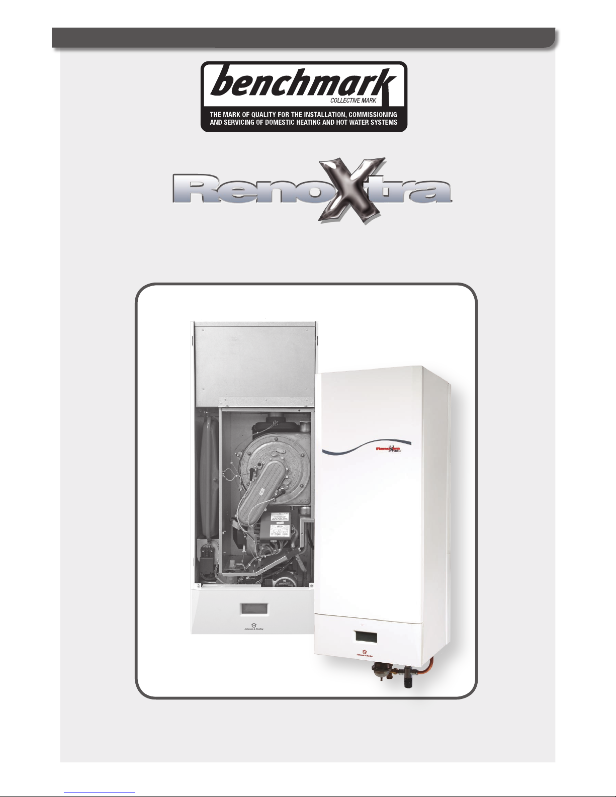
This checklist should be filled out at each
annual service
COMMISSIONING
CHECKLIST & SERVICE RECORD
37
Telephone: 01604 762881
19. BENCHMARK CHECKLIST & SERVICE RECORD
Page 38
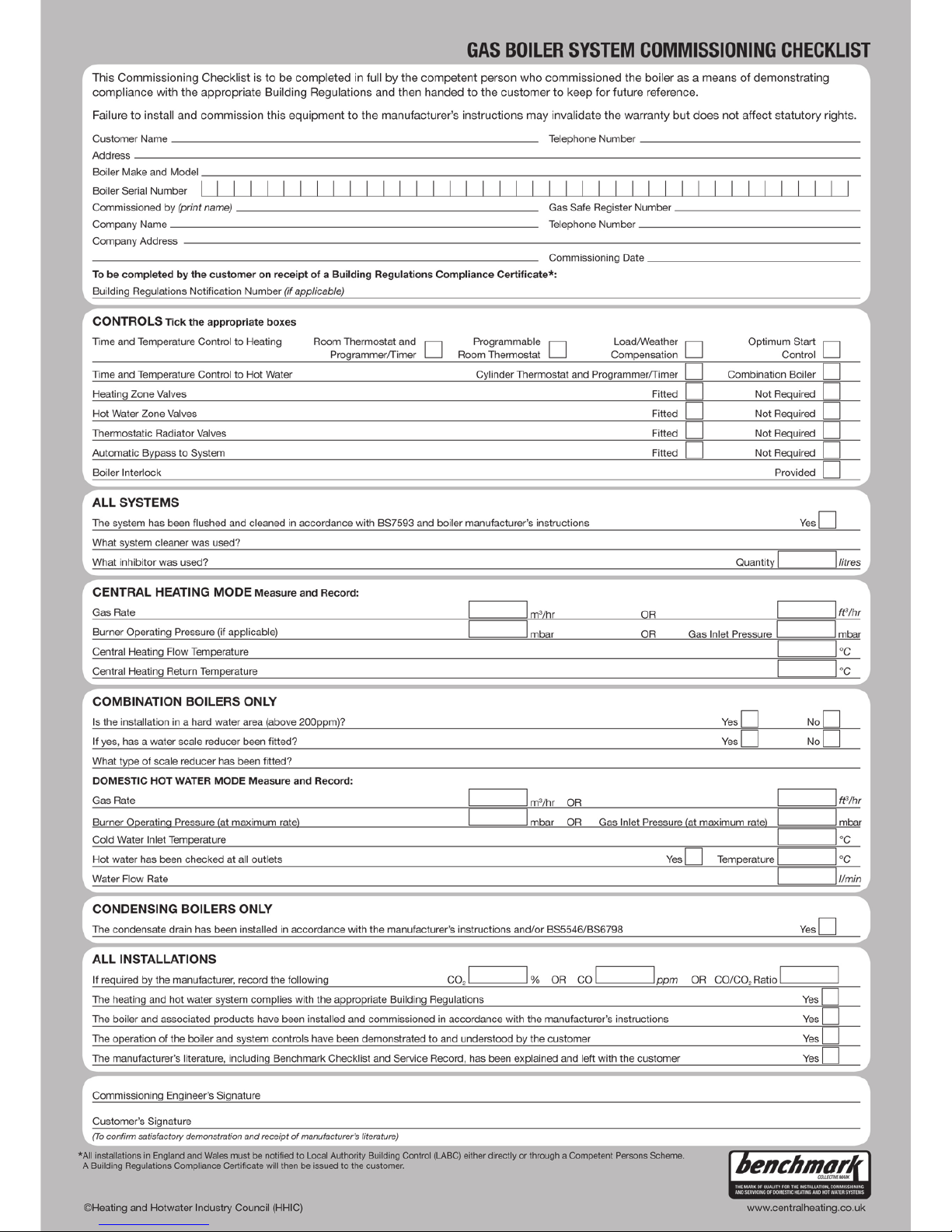
Page 39
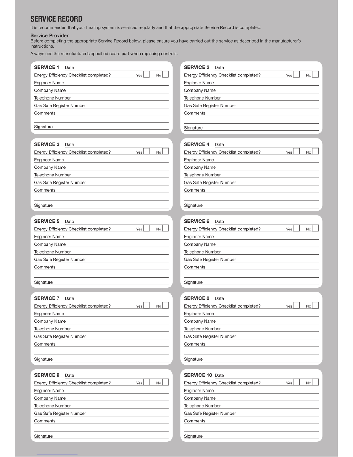
Page 40
Johnson & Starley
R E L I A B I L I T Y Y O U C A N T R U S T
Rhosili Road, Brackmills, Northampton NN4 7LZ
In the interest of continuous development Johnson & Starley Ltd reserve the right to change specifications without
prior notice
RENO BO ILER
RANG E
ECON OMA IRE WAR M A IR HEAT ERS
HI-S PEC WA RM A IR HEAT ERS
HEAT REC OVE RY
HOME ‘N ’ D RY
VENT ILAT ION
DRYF LOW
RENO XTR A
CENT RAL EX TRA CT
VENT ILAT ION SY STE M
DRAV O
Johnson & Starley are the leading UK &
European manufacturers of a complete range
of
Domestic Warm Air Heaters.
All the heaters suit both Replacement and
Upgrade needs and are compliant with the
new (2006) amendments
to Part L of the
Building Regulations.
HOME COMFORT SOLUTIONS
Company Details
Website Address www.johnsonandstarley.co.uk
Telephone Number
01604 762881
(Main switchboard)
Fax Number 01604 767408
Spares
Telephone 01604 707012
Fax 01604 762884
Sales
Telephone 01604 707012
Fax 01604 764879
Service
Telephone 01604 707011
Fax 01604 707017
Warm Air Upgrade Enquiry Service
Telephone 01604 707026
Fax 01604 707017
COMMERCIAL & INDUSTRIAL
H&V SOLUTIONS
Company Details
Johnson & Starley Dravo Division Industrial H&V
Website Address www.dravo.co.uk
T elephone Number 01604 707022
Fax Number 01604 706467
 Loading...