

Page 1
www.johnsonandstarley.co.uk
USER’S INSTRUCTIONS
These instructions are to be left with the User
Publication No. ZZ 1464
September 2013
QUANTEC
REGULAR
Kompact
High Efficiency Boiler
Quantec 16RK - G.C. No. 41-416-19
Quantec 24RK - G.C. No. 41-416-20
Page 2
www.johnsonandstarley.co.uk
2
CONTENTS
1 General information 3
2 The Boiler Control Panel 3
3 To Light the Boiler 3
4 Operarting Functions 4
5 Reset Procedure 5
6 Servicing & Mainenance 5
7 Escape of Gas 5
8 Cleaning 5
9 Trouble Shooting 6
NOTE
This appliance is not intended for use by persons (including children) with reduced physical,
sensory or mental capabilities, or lack of experience and knowledge, unless they have been given
supervision or instruction concerning use of the appliance by a person responsible for their safety.
Children should be supervised to ensure that they do not play with the appliance.
THESE INSTRUCTIONS SHOULD BE LEFT WITH THE USER
AFTER INSTALLATION
The Benchmark Scheme
Johnson & Starley Ltd is a licensed member of the Benchmark Scheme which
aims to improve the standards of installation and commissioning of domestic heating and hot water systems in the UK and to
encourage regular servicing to optimise safety, efficiency and performance.
Benchmark is managed and promoted by the Heating and Hotwater Industry Council. For more information visit www.
centralheating.co.uk
Please ensure that the installer has fully completed the Benchmark Checklist on the inside back pages of the installation
instructions supplied with the product and that you have signed it to say that you have received a full and clear explanation
of its operation. The installer is legally required to complete a commissioning checklist as a means of complying with the
appropriate Building Regulations (England and Wales).
All installations must be notified to Local Area Building Control either directly or through a Competent Persons Scheme. A
Building Regulations Compliance Certificate will then be issued to the customer who should, on receipt, write the Notification
Number on the Benchmark Checklist.
This product should be serviced regularly to optimise its safety, efficiency and performance. The service engineer should
complete the relevant Service Record on the Benchmark Checklist after each service.
The Benchmark Checklist will be required in the event of any warranty work and as supporting documentation relating to home
improvements in the optional documents section of the Home Improvements.
In the interest of continuous development Johnson and Starley reserve the right to change specification without prior notice.
Johnson and Starley prides itself on it’s ability to supply spare parts quickly and efficiently.
Page 3
3
Sales/Spares 01604 707012 Replacement Help Line 01604 707011
1. GENERAL INFORMATION
WARNING: THIS APPLIANCE MUST BE EARTHED
IMPORTANT: IT IS A STATUTORY REQUIREMENT THAT ALL GAS APPLIANCES BE
INSTALLED BY COMPETENT PERSONS, (i.e. GAS SAFE REGISTERED INSTALLERS.
GAS SAFE MEMBERSHIP ENQUIRIES - TEL: 0800 408 5500) IN ACCORDANCE WITH
THE GAS SAFETY (INSTALLATION AND USE) REGULATIONS (CURRENT EDITION).
FAILURE TO COMPLY WITH THESE REGULATIONS MAY RESULT IN PROSECUTION.
1.1 Part of the installation and commissioning of this appliance is related to instructions for use by the heating
engineer to the user where specific requirements may occur.
1.2 The QuanTec Regular Kompact is a wall mounted, room sealed, condensing boiler, featuring full sequence
automatic spark ignition and fan assisted combustion. Due to the high efficiency of the boiler, condensate
is produced from the flue gases and this is drained to a suitable disposal point through a plastic waste pipe
at the base of the boiler. A condensate ‘plume’ will also be visible at the flue terminal.
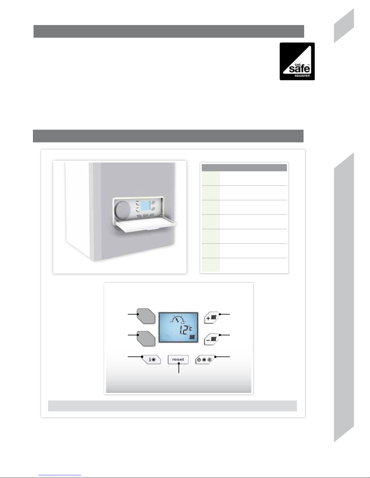
2. THE BOILER CONTROL PANEL
FIGURE 2. LCD DISPLAY FUNCTIONS
K7 K1
K6 K2
K3 K5
K4
Item Description
K1
CH - Central Heating +
K2
CH - Central Heating -
K3
Installer information
K4
Reset
K5
Summer/Winter mode
K6
Installer function only
K7
Installer function only
Page 4
www.johnsonandstarley.co.uk
4
3. TO LIGHT THE BOILER
If a programmer is fitted refer to seperate instructions for the programming before
continuing,
3.1 Check that the electric supply to the boiler is on.
3.2 Set the mode control to winter usinf ‘K5’.
3.3 Set the Heating temperature control to ‘max’ using ‘K1’.
3.4 Check that all external controls, e.g. programmer, room thermostat and cylinder
thermostat, are ON.
3.5 The boiler will commence the ignition sequence supplying heat to the central
heating, if required.
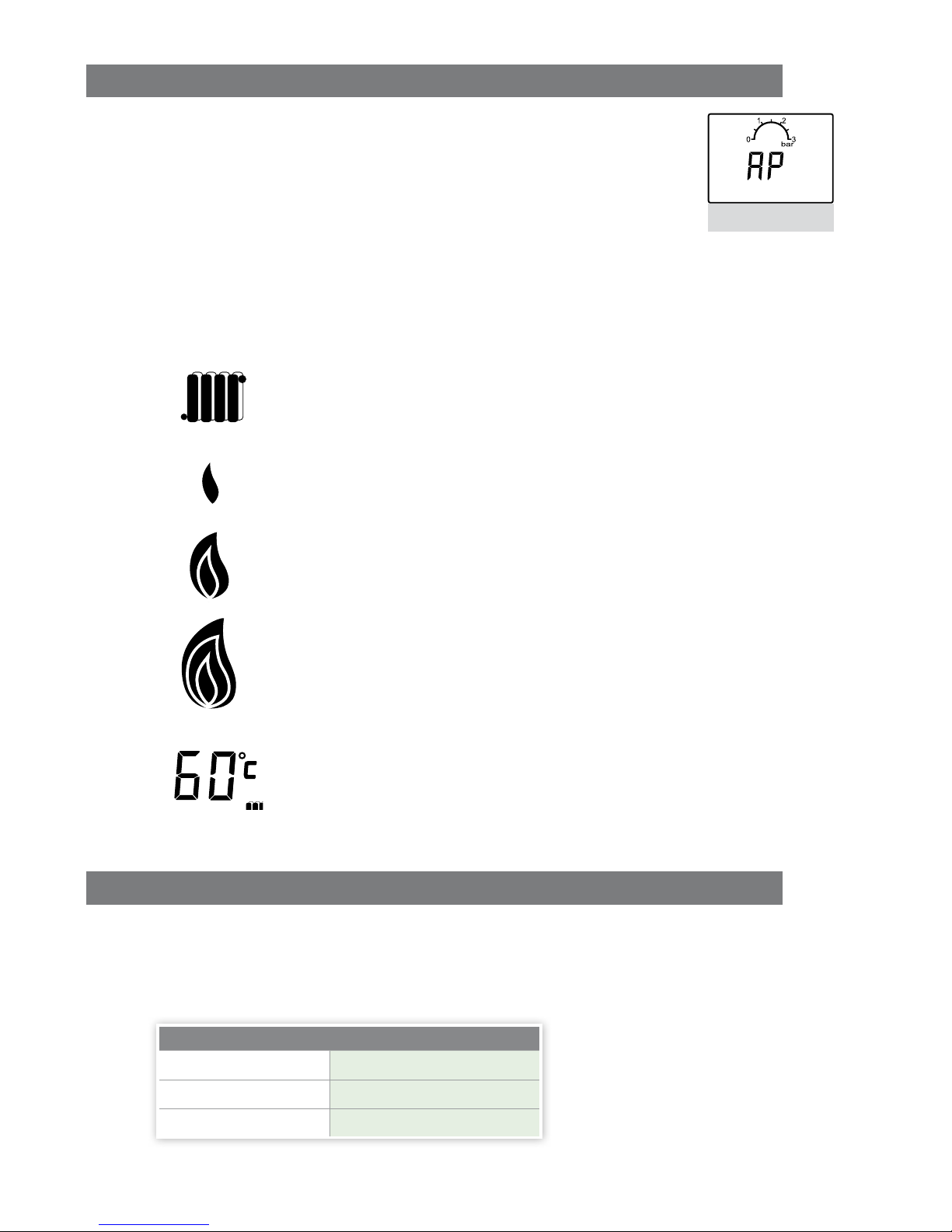
NOTE: In normal operation the boiler status disply will be.
DISPLAY CODES
Call for heat
Burner on low
Medium
High
Temperature of supply
4. OPERATING FUNCTIONS
4.1 OPERATING THE CENTRAL HEATING
When the boiler fire in CH mode it fires for 1 minute, modulating the boiler. The display will flash showing
the radiator, the small flame and temperature. A flame symbol increases with the demand for heat. Once
temperature is reached the display will go back to standby.
Approximate flow temperatures for the boiler thermostat settings are:
TABLE. 2
Button Setting CH Flow Temperature °C
Minimum 40°C
Maximum
80°C
FIGURE 3.
Page 5

5
Sales/Spares 01604 707012 Replacement Help Line 01604 707011
4.2 TO SHUT DOWN THE BOILER
Set the mode to OFF
To relight the boiler repeat the procedure detailed in ‘To light the boiler’.
4.3 FROST PROTECTION
If no system frost protection is provided and frost is likely during a short absence from home, leave the
heating controls (if fitted) at a reduced temperature setting. For longer periods, the entire system should be
drained.
If the system includes a frost thermostat then, during cold weather, the boiler should be turned OFF at the
time switch (if fitted) ONLY. The mains supply should be left switched ON, with the boiler thermostat left in
the normal running position.
4. Turn the filling loop isolation valves to the open position. The system will now fill.
5. Wait for pressure gauge dial to reach 1 to 1.5 bar.
6. Close the filling loop isolation valves.
7. Disconnect the filling loop at left hand side and angle upwards.
8. Attach the two caps as shown on point 2.
4.5 CONDENSATE DRAIN
The condensate drain must not be modified or blocked.
Blockage of the condensate drain, caused by debris or freezing, can cause automatic shutdown of the
boiler.
If freezing is suspected and the pipe run is accessible an attempt may be made to free the obstruction by
pouring hot water over the exposed pipe and clearing any blockage from the end of the pipe. If this fails to
remedy the problem the assistance of a Gas Safe Registered Engineer or in IE a Registered Gas Installer
(RGII) should be sought.
5. RESET BOILER
Press the reset button. See Table 1 Button K4.
6. SERVICING & MAINTENANCE
It is recommended that a full maintenance check be carried out annually on the appliance. It is also
recommended to take out a further service agreement on the expiry of the guarantee period.
You can obtain further information on this from your gas supplier.
The appliance should be checked /serviced by a GAS SAFE registered installer.
If you require service on your appliance please contact your local installer or gas supplier.
On completion of the service the installer should fill in the service section at the rear of the BENCHMARK log
book. All installers registered with GAS SAFE carry an identification card. This card will have an ID number
which should be recorded in your logbook.
If you have any queries regarding your installer you can contact GAS SAFE
by telephone on 0800 408 5500.
The appliance should be serviced at least once a year by a Gas Safe
Registered Engineer or in IE a Registered Gas Installer (RGII).
7. ESCAPE OF GAS
Should a gas leak or fault be suspected contact the National Gas Emergency Service without delay.
Telephone 0800 111 999
Do NOT search for gas leaks with a naked flame.
8. CLEANING
For normal cleaning simply dust with a dry cloth.
To remove stubborn marks and stains, wipe with a damp cloth and finish off with a dry cloth.
DO NOT use abrasive cleaning materials.
Page 6

www.johnsonandstarley.co.uk
6
ERROR CODES
E01
Ingnition lockout
Check other as appliances work
Reset boiler
Contact installer
E02
False flame lockout Contact installer
E03
Overheat lockout
Ensure water in heating system
Bleed radiators & check system pressure
Check radiator valves are open
Reset boiler
Contact installer
E05
Fan Fault Contact installer
E08
Flame Circuit Failure Contact installer
E09
valve feed back ERROR Contact installer
E12
EEPROM lockout Contact installer
E15
Sensor drift lockout
Ensure water in heating system
Bleed radiators & check system pressure
Check valves are open
Reset boiler
Contact installer
E16
E17
E18
Sensor Stuck Lockout
Ensure water in heating system
Bleed radiators & check system pressure
Check valves are open
Reset Boiler
Contact installer
E21
ADC Lockout Contact installer
E33
Return Thermistor Fault Contact Installer
E34
Low Power Supply Lockout Contact installer or Electrcian
E35
Flow Thermistor Fault Contact Installer
12. TROUBLE SHOOTING
Page 7

7
Sales/Spares 01604 707012 Replacement Help Line 01604 707011
FAULT CODES
F07
Exhaust gas temperature too high
Ensure water in heating system
Bleed radiators & check system pressure
Check radiator valves are open
Wait 15 minuets, turn power OFF & ON
Contact installer
F13
Remote Reset Lockout
Turn power OFF and ON
Press Reset
Contact Boiler
F53
Flue Temperature Sensor error Contact installer
GAS LEAKS
DO NOT OPERATE ANY ELECTRICAL SWITCHES, OR USE A NAKED FLAME
TURN OFF GAS SUPPLY
VENTILATE THE AREA BY OPENING THE DOORS AND WINDOWS
CALL THE NATIONAL GAS EMERGENCY SERVICES ON
TEL:
0800 111999
Page 8

Anniversary 1922 - 2012
Johnson & Starley Ltd
Rhosili Road, Brackmills,
Northampton NN4 7LZ
Reception
01604 762881
Sales/Spares
01604 707012
Service/Warm air upgrade
01604 762881
Warm air upgrade
01604 707011
Johnson & Starley Dravo Division Industrial H&V
Sales
01604 707022
www.dravo.co.uk
 Loading...