

Page 1
JANSTAR
MODULATING WARM AIR HEATER
with SYSTEM E-T Control
INSTALLA TION, COMMISSIONING & SERVICING INSTRUCTIONS
G.C. No 42 451 07
This appliance has been tested and certified for use with natural gas.
1. GENERAL DESCRIPTION
1
Publication No. ZZ 757/9
June 2000
9
2
3
4
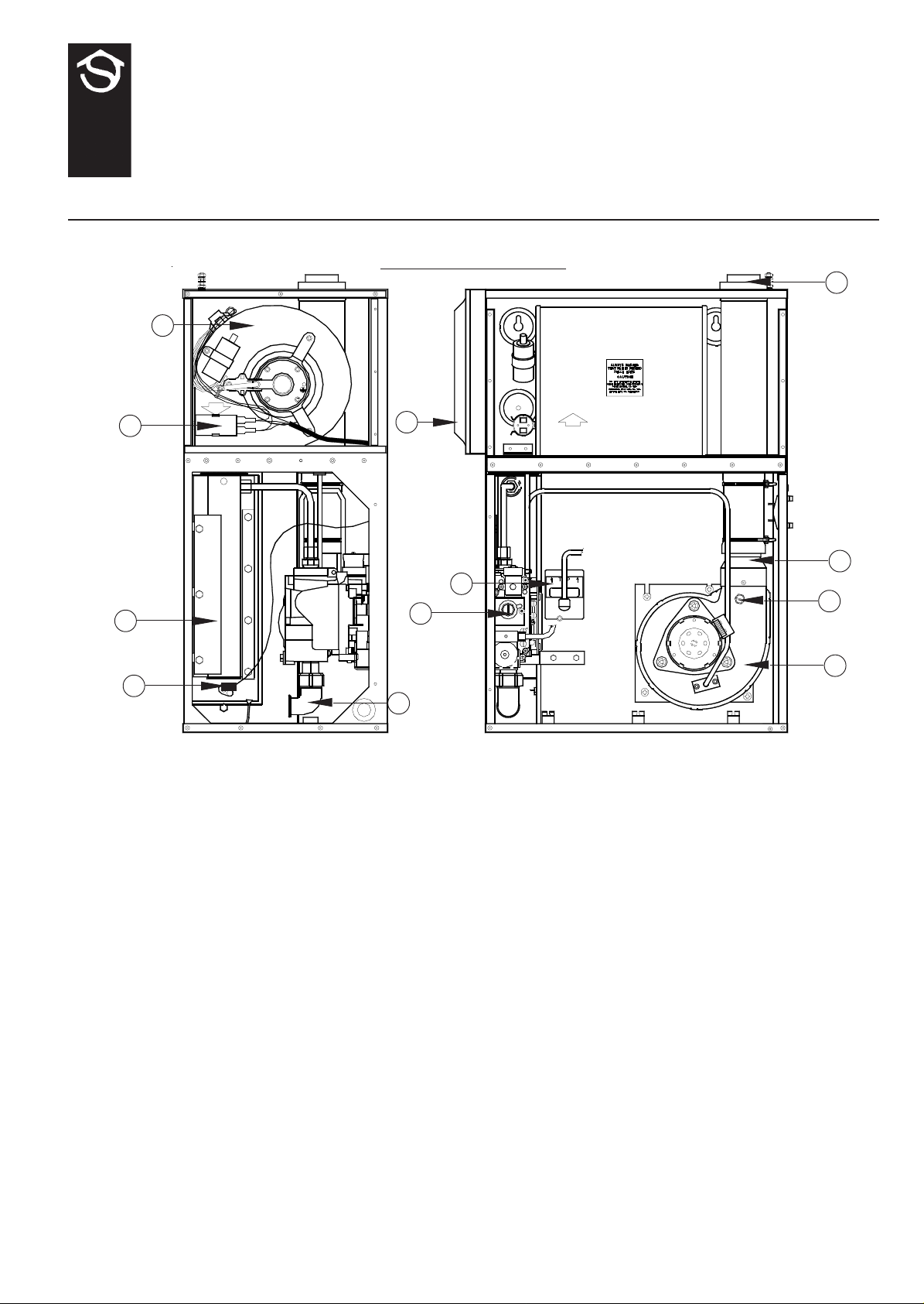
Key Description Key Description
1 Air circulating fan 7 Fan delay/ Overheat limit control
2 Fan energy capacitor 8 Air filter (L H shown)
3 Burner assembly 9 Flue outlet/combustion air inlet
4 Ignition/detection electrode 10 Fan to flue connection
5 Gas connection 11 Flue gas test point
6 Multifunctional control 12 Combustion air fan
8
10
7
11
6
12
5
Fig. 1
JANSTAR Principal Components
1. 1 The Johnson & Starley JANST AR is a all mounted, room sealed, fan assisted, down flow warm air heater with SYSTEM
E-T control. It is designed for use with a concentric air inlet/flue, which enables combustion air to be admitted to the
burner, whilst combustion products are discharged to the outside, via a concentric terminal.
1. 2 The air heater output varies automatically between 8.0 kW (27,300Btu/h) and 2.0 kW (6,800 Btu/h) for horizontal flued
installations, and 8.5 kW (29000Btu/h) and 2.8 kW (9600Btu/h) for vertical flued installations.
1. 3 The appliance is supplied assembled for left hand return air entry. For conversion to right hand return entry, refer to
Section 4. If return air is via the top of the fan chamber, a side blanking plate (Pt No W800-0133000) is required. An
adaptor kit is available which permits the appliance to be converted to an upflow model. The appliance may be base duct
mounted. The JANSTAR is also provided with the facility for connection to a remote time control (not supplied), with
volt-free contacts (i.e. The switching supply is provided by JANSTAR), to enable selection of operating times.
1. 4 A mesh filter, for air return duct mounting, is supplied as standard. However, a Cleanflow electronic filter is offered as an
alternative option.
THIS APPLIANCE CONFORMS TO BS EN 55014
1
Page 2
ZZ757/9
Installation shall be in accordance with the current editions of:Building Standards (Scotland) (Consolidation) Regulations
Building Regulations
Gas Safety (Installation and Use) Regulations (as amended)
BS7671 Institute of Electrical Engineers (IEE.) Wiring Regulations
BS6891 Installation of Low Pressure Gas Pipework of up to 28mm (R1) in domestic premises (2nd family gases).
BS5440 Pt.1 (Flues for Gas Appliances)
BS5440 Pt.2 (Air Supply for Gas Appliances)
BS5864 Installation of Gas Fired Ducted Air Heaters
British System Design Manual “Gas Fired Warm Air Heating”
Model and Local Authority Bye-laws
IMPORT ANT : ST ATUTE LAW DEFINES THA T ALL GAS APPLIANCES MUST BE INST ALLED BY COMPETENT
PERSONS, (i.e. CORGI REGISTERED INST ALLERS) IN ACCORDANCE WITH THE GAS SAFETY (INST ALLA TION
AND USE) REGULA TIONS (CURRENT EDITION). F AILURE T O COMPL Y WITH THESE REGULA TIONS MAY
LEAD TO PROSECUTION.
2. HEA TER COMPARTMENT AND CLEARANCES (See BS5864)
2. 1 A minimum clearance of 15mm (5/8 in) at either side of the heater, and 150mm (6in) above the heater, should be allowed.
For service access, a minimum of 450mm (18in) is required at the front of the heater, and 75mm at the left hand side.
Space must also be allowed, in a compartment installation, to permit the removal of the heater. If a Cleanflow electronic
air filter is to be fitted in the compartment, allowance must be made for this in the width of the compartment. The
compartment must be of a fixed rigid structure and the internal construction must be of half-hour fire resistance to
internal fire; the inside lining or finishing of the enclosure must be noncombustible or a class 1 finish (see also BS 476).
2. 2 In airing cupboard installations, the part used as the air heater compartment must comply with the relevant section of
BS 5864 and must be completely separated by either a noncombustible partition or a perforated metal partition with the
perforations not exceeding 13mm (0.5in).
2.3 In under-stair installations, the compartment must comply with the relevant section of BS5864, provided that, in addition,
all internal surfaces, including the base, are of, or lined with noncombustible material.
3. VENTILA TION AND COMBUSTION AIR
3.1 A room sealed appliance does not require a combustion air vent in the room or internal space in which it is installed. If
the appliance is installed in a compartment, the minimum total free area of the high and low level ventilation air vents
must be as specified in Table 1 below, (in reference to BS5440 Pt 2, Table 1).
Position of Air from room Air direct
air vents or internal space from outside
High level 89cm2 (14 in2) 45cm2 (7 in2)
Low level 89cm2 (14 in2) 45cm2 (7 in2)
T ABLE 1
MINIMUM EFFECTIVE AREAS
4. ADAPTING TO RIGHT HAND AIR ENTR Y
4. 1 Remove the return air spigot and the short side cover from the left hand side of the appliance, and lay to one side.
4. 2 Remove the long side cover from the right hand side of the appliance, and reassemble it on the left hand side, ensuring
that the slots are towards the front of the appliance.
4. 3 Reassemble the short side cover and the return air spigot ton the right side of the appliance, ensuring that the slots in the
side cover are towards the front of the appliance.
5. DUCT SYSTEM
(See British Design Manual - Gas Fired Warm Air Heating).
IMPORTANT: All duct work MUST be mechanically secured, and sealed with ducting tape.
5.1 RETURN AIR
5.1.1 Room sealed appliances may be installed without return air ducting, provided that the path between the return air
grille and the appliance return air inlet is protected in such a manner that the required airflow will be maintained at
all times. Where no ducting is fitted, a finger guard (Ref. FGJ, available from Johnson and Starley Ltd.), MUST be
fitted.
2
Page 3

5.1.2 The return air system should be constructed of fire-resistant material. It is extremely important that the correct
size of return air grilles and ducting is used. The return air duct size should be NOT LESS THAN 225mm x
200mm (9in x 8in). If flexible duct is used, the duct diameter should be NOT LESS THAN 250mm (10in) dia. The
return air grille should have a free area of not less than 645cm2(100in2).
5.1.3 An adequate and unobstructed return air path is essential from areas not served by a directly ducted return and to
which warm air is delivered. All such rooms should be fitted with relief grilles which have a free area of
0.0088m2/kW (1in2/250Btu/h) of heat supplied to the room. The only exceptions are kitchens, bathrooms, and
WC’s.
5.1.4 For top return, a ‘starter ’ knockout is provided to assist in creating the required aperture in the fan chamber top.
5.2 W ARM DELIVERED AIR
5.2.1 All duct work, including riser ducts, should be fully insulated with 50mm (2in) glass fibre or similar. If extended
duct runs are taken below floor level, these should be similarly insulated and in addition, wrapped with a sound
proof barrier, and protected from crushing.
5.2.2 The duct system should be carefully designed (as detailed in the guidelines in the British Design Manual) to suit
the needs of its specific heating requirements and building layout. The type of duct system, i.e. radial/extended/
stepped plenum should be installed using the least number of fittings to minimise air flow resistance.
6. INSTALLATION REQUIREMENTS
6.1 AIR HEA TER
6.1.1 Heater mounting is by means of five screws (provided) into a wall or structure sufficiently rigid to support the
appliance without deflection (for mounting hole positions see Fig. 8. The weight of the appliance is 25kg.
Recommendedscrew size is No 10 x 2 in with suitable wall plugs. Attach the plenum to the underside of the
appliance using the four M4 x 16 screws and gasket provided. NOTE: Ensure that the aperture in the gasket is
correctly aligned with the warm air outlet on the underside of the appliance. Position the return air and warm air
outlet spigots to suit the application before mounting the assembly on the wall. For replacement, the appliance
may be fitted to an existing base plenum, with any blanking plates being mechanically secured and sealed.
6.2 FLUES (See BS 5440 Pt. 1 Flues)
6.2.1 The maximum allowable flue length is 5.0m plus one 90o bend for horizontally flued appliances, and 11.0m plus
terminal for vertically flued appliances.
6.2.2 The minimum allowable flue length is 350mm plus one 90o bend for horizontally flued appliances, and the length
of the terminal (1240mm) for vertically flued appliances. For applications where the flue exits directly through a
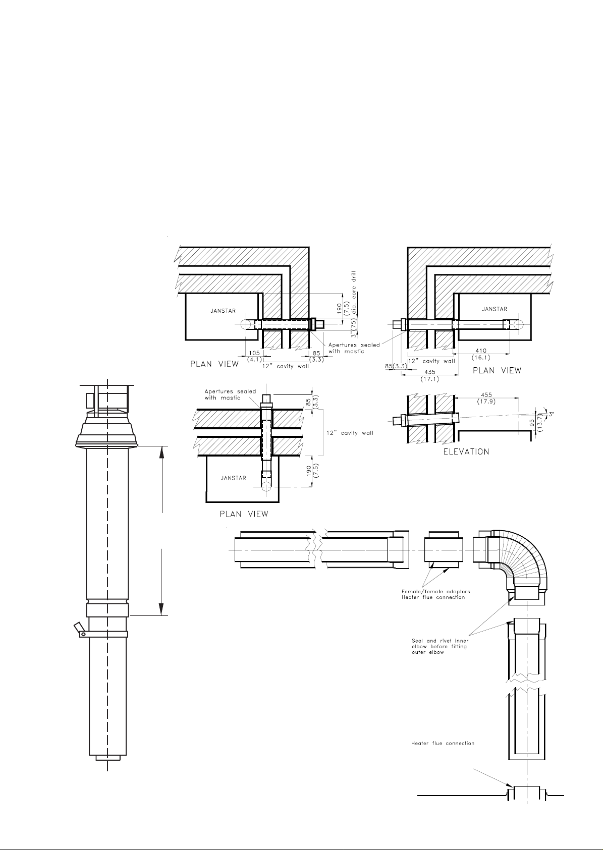
wall, the telescopic flue supplied with the heater may be used, as shown in Fig. 2.
6.2.3 The horizontal flue shall be installed with horizontal runs having a continuous fall to the terminal of at least 1.:50
(refer to T able 2 below).
Flue Length Fall
1 m 20mm
2 m 40mm
3 m 60mm
4 m 80mm
5 m 100mm
T able 2
1:50 flue fall
6.2.4 The overall flue shall be kept as short as possible, with the minimum number of bends. The flue should terminate
in its direction, with the terminal section meeting the outer side of the wall, or roofing at the point where it begins
to flare out, (refer to Fig. 2). One 90o horizontal bend is equivalent to 1m of straight flue, a 45o horizontal bend is
equivalent to 0.5m of straight flue. One 90o vertical bend, where the bend radius is equal to the flue diameter, is
equivalent to 1.3m of flue; one 90o vertical bend, where the bend radius is equal to 0.5 flue diameter, is equivalent
to 2.9m of flue; and a 45o bend, where the bend radius is equal to the flue diameter, is equivalent to 0.85m of flue.
6.2.5 Sufficient support brackets (not supplied) shall be fitted to bear the weight of the total flue system.
6.2.6 The annular space between the flue assembly and surrounding structure must be sealed. If a cement sealant is
used, then the flue pipe must be coated with a suitable varnish a that point, to prevent corrosive attack of the
aluminium pipe.
6.2.7 For a vertical flue, a 60/100mm dia. concentric flue available from Johnson & Starley must to be used.
6.2.8 For a horizontal flue, the terminal supplied must be used. It shall be positioned in accordance with the
recommendations of BS 5440 Pt. 1, Clause 8 and Appendix B, and be guarded against damage and for
protection of passers-by, by using a terminal guard (Tower Flue Components Type K4), obtainable from builders’
merchants and Johnson & Starley (Pt No 1000-0002870).
3
ZZ757/9
Page 4
ZZ757/9
6.2.9 The flue/air duct spigot on the appliance is female. For horizontal flued appliances, the flue/air duct should be
constructed that such that condensate cannot leak from the joints. Therefore, on vertical runs, all female ends
should face away from the appliance, and on horizontal runs should face towards the appliance, as depicted in
Fig. 3. To reverse the lay of joints, it is recommended to use male/male adaptors, available from Johnson &
Starley (Pt Nos. 1000-0002840 [inner], and 1000-0002850 [outer]). The flue should be constructed working
from the appliance towards the telescopic flue.
6.2.10 Construction of flue joints.
a. Coat the end of the inner tube with silicone sealant capable of withstanding temperatures of up to 200
(not provided), and insert it fully into the female end of the next tube.
b. Using 3.3mm dia. drill, drill one hole through the assembly and secure with 1 x blind pop rivet (provided).
c. Fit 1 x centring clip (provided) over the tube, immediately down flow of the joint.
d. Slide the outer tube over the centring clip; assembly, secure and seal the outer joint in the same manner as
the inner joint.
NOTE: Only use the BLIND POP RIVETS PROVIDED.
O
C
300mm
minimum
Fig. 2
Telescopic flue applications
Fig. 3
Vertical flue application
Fig. 4
Flue jointing
4
Page 5

6.3 CONDENSATE
6.3.1 When firing at low rate, the unit will produce condensate which must be drained away. A JDT1 kit, which
externally drains the condensate away from the flue terminal is available for horizontal flued applications. Vertical
flued applications require the fitment of an in-line condensate trap within 0.5 m of the unit, in the first vertical
flue run, and before any bends in the flue run. Such a trap, with a 32 mm male drainage connection, is available for
this purpose.
6.3.2 Condensate from vertical flued applications must be drained away using 32 mm or 20 mm internal diameter, rigid
plastic pipe, connected to the condensate drain using KUTERLITE 700 or similar straight coupling. The pipe
should be installed in such a manner, that it forms a continuous downward slope away from the unit at a minimum
3o angle (6 mm per 100 mm, or, 0.75 in per foot run), and that the risk of mechanical damage and interior
interference is minimised. The pipe is to be protected against frost damage.
6.4 ELECTRICAL
6.4.1 Mains: The heater is supplied with mains cable (PVC sheathed, high temperature resistant, 3 core [BrownBlue-Green/Yellow], 6A, 0.75mm2), connected to a terminal block and exiting from the heater at the bottom right
hand rear. The cable is suitable for a 230V 50Hz single phase supply and must be protected by a 5A fuse, and an
earth wire must be connected. A double pole switch or fused spur box should also be used. All wiring conform to
I.E.E. regulations, (current edition).
6.4.2 Thermista-stat: A Thermista-stat is provided with the appliance; this acts as a room thermostat, and also as a
summer air flow switch. The Thermista-stat wiring is to be connected to terminals 3 and 4 on the air heater
control panel, (marked ‘THERMISTA-STAT’), polarity being unimportant. It should be located where there is free
air circulation, and approximately 1.5m (5ft) from the floor. The following locations should be avoided.
ZZ757/9
a. In a room where temperature is greatly affected by the sun or any other heat source (e.g. radiant fire, wall
light fitting or TV set).
b. Near an outside door or windows, or on an outside wall.
c. Where it can be affected by warm air ducts, diffusers, waste pipes or the heater itself.
d. Where it can be subject to vibration.
6.4.3 Time Control: If an external time control (not supplied) is to be fitted, connect the live supply to terminal 7,
the neutral to terminal 6, and the time-switch output to terminal 5. If no time control is fitted, link terminal 5
and 7.
6.5 GAS (see BS 5864 and BS 6891)
6.5.1 An independent gas supply pipe from the gas meter is to be preferred wherever possible. However, when this is
not possible, the pipe must be capable of taking the complete input of the heater and all other gas appliances being
served by this same pipe. This supply should be suitably sized to conform to British Standards requirements of no
more than 1.0 mbar (0.4 in. wg.) pressure drop (see table of discharge in BS 6891).
6.5.2 The 1/2 in union gas cock (supplied) must be fitted externally in the gas inlet of the heater for easy isolation during
servicing. The gas pipe should be fitted and installed as to be durable, substantial and gas tight. Gas entry to the air
heater may be through the left hand side, right hand side front, or rear, to an Rc1/2 (1/2in B.S.P. internal (taper)
thread).
7. COMMISSIONING
7. 1 Ensure the following:
7.1.1 Gas and Electrical supplies are OFF.
7.1.2 Filter, fan and fan compartments are free from obstructions.
7.1.3 All registers or grilles are open and conform to design specifications.
7.1.4 Return, relief and ventilation air installations are adequate.
7.1.5 Adhesive label is removed from the centre of the combustion air fan to expose the motor cooling slots.
7.2 Turn ON the gas supply to the heater.
7. 3 Test for gas soundness at supply, Multifunctional control, Pilot and Main burners using proprietary detection fluid,
sealing any leaks found, and purge the whole gas pipe as described in BS 6891.
7. 4 Set the Thermista-stat to maximum setting (9).
7. 5 Ensure that the remote time control (if fitted) is in the ON mode.
7. 6 Switch on the electrical supply to the heater. The combustion air fan will start up immediately; after a minimum of 30
seconds, the burner will automatically ignite and the green ‘BURNER ON’ indicator will illuminate.
5
Page 6

ZZ757/9
7.6.1 If the burner fails to light (amber ‘LOCKOUT’ illuminated): Reinstate the ignition sequence by allowing 10
seconds to elapse, and then press and release the ‘RESET’ button.
7.6.2 If the burner ignites but then extinguishes: An automatic purging sequence will take place, which lasts for
approximately 30 seconds. Following this, a second ignition will take place.
7. 7 Set the time control (if fitted) to the required ‘Heating On’ periods and adjust the Thermista-stat to the desired comfort
setting. The burner will then initially operate at maximum output until it reaches the set comfort level, whereby the heater
modulates to maintain the required comfort level.
7.8 BURNER PRESSURE CHECK:
Note: The Burner pressure is factory set and MUST NOT BE ADJUSTED.
7.8.1 Turn the gas and electrical supplies to OFF.
7.8.2 Link Terminal block connection ‘3’ to ‘TEST’ terminal.
7.8.3 Referring to Fig. 5, remove and retain the Burner Pressure Test Point blanking screw, and fit pressure a test gauge
to the test point.
7.8.4 Turn ON the gas and electrical supplies.
7.8.5 Reinstate the ignition sequence as detailed in sub-para 7.6.1
7.8.6 Ensure that the burner ignites, and allow 15 minutes of operation to elapse to ensure stability.
7.8.7 Referring to Table 3, ensure that the burner pressure is within the limits specified for the installed flue length.
7.8.8 If the differential burner pressure is not within the limits stated, run the appliance for a further 10 minutes and
then re-check the burner pressure. If the pressure is still not within the stated limits, contact Johnson and Starley
Ltd. Service Department, since rectification requires the use of special equipment.
7.8.9 Turn the gas and electrical supplies to OFF.
7.8.10 Remove the link from Terminal block connection ‘3’ to ‘TEST’ terminal.
7.8.11 Remove the pressure test gauge, and refit pressure test point blanking screw.
7.8.12 Turn ON the gas and electrical supplies.
7.9 WARM AIR SYSTEM BALANCING:
7.9.1 Set the Thermista-stat to the ‘SUMMER AIRFLOW’ position (fully clockwise switched position), and check
that the air circulation fan is running full speed, without the burner operating.
7.9.2 Balance the system to provide the required volume proportions at the warm air outlets.
Note: If the system includes ceiling diffusers, it is important that the velocities of air through these (except in
very small rooms such as bathrooms) are at least 1.5m/s (300ft/min). In order to achieve this, it may be necessary
to blank off part of the outlet face.
7.9.3 Reset the Thermista-stat to the require comfort level setting.
7.10 AUTOMATIC CONTROLS CHECK: Lighting the heater and allowing it to operate for a short time will effectively
check these controls.
7.11 SAFETY CHECK:
7.11. 1 Turn OFF the gas supply at service cock and ensure that Multifunctional control fail-safe operates (indicated by
loud click from Multifunctional control).
7.11.2 Turn the gas supply ON at service cock, and ensure that the burner ignites.
7.12 FAN PERFORMANCE: No provision is made for fan speed adjustment, since the fan speed is automatically determined
by the appliance, and the demand for heat.
HORIZONT AL FLUE VERTICAL FLUE
APPLICATIONS APPLICATIONS
kW MJ/h Btu/h kW MJ/h Btu/h
INPUT 9.80 35.3 33,500 10.5 37.8 35,800
OUTPUT 8.0 29.0 27,300 8.57 30.86 29,200
Gas rate cv 0.92m3/h (32.3 ft3/h)
1037 Btu/h
Burner setting 8.9mbar (3.6 in wg) 10.2mbar (4.1 in wg)
pressure (hot)
Main Injector BRAY 15/850
T able 3
Main Burner Pressure Settings
6
Page 7
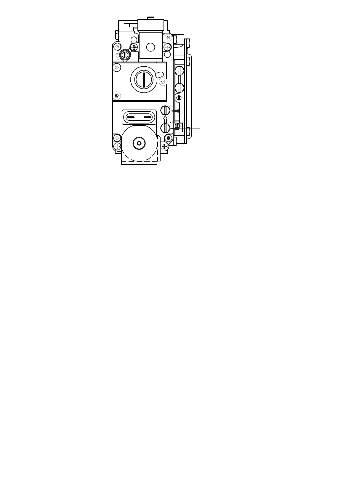
Fig. 5
Multifunctional control
ZZ757/9
Burner pressure test
point
Inlet pressure test point
8. INSTRUCTIONS FOR USERS
8.1 If the building is unoccupied, ensure that the Instructions for User are left taped to the air heater for the User, and
Installation Instructions are left at or near the air heater for use on future service calls.
8. 2 If the building is occupied, hand the User Instructions over and ensure that the User understands:
8.2.1 How to operate the Thermista-stat/room thermostat, time and heater ON/OFF switch and summer air circulation
switch, and that the time control must be reset following a power failure.
8.2.2 How to turn off the appliance, and switch off electrical supply to the heater.
8.2.3 How to remove, clean and refit the air filter and at what intervals (i.e. fortnightly, or for new houses, weekly).
8.2.4 How to control the heating system by opening and closing warm air outlets.
8.2.5 That the heater must be serviced at least once a year by a competent person to ensure efficient and safe operation.
8.2.6 That the red instructions for safe use have been pointed out and understood.
8.2.7 That the air grilles on the heater or heater compartment; grilles and ventilators in the walls, windows or doors of
the building must not be obstructed.
8.2.8 That expert help must be obtained if malfunction of the appliance occurs.
8.2.9 How to obtain summer air circulation.
8.2.10 How to rest the appliance if LOCKOUT occurs.
9. SERVICING
IMPORTANT: Ensure that gas and electricity supplies are isolated before commencing any maintenance or
replacement of components. After completion of any maintenance, always test for gas soundness and
carry out a complete functional test of the appliance in accordance with Commissioning Instructions.
9.1 ROUTINE MAINTENANCE:
9.1.1 Operate appliance and check for correct function.
9.1.2 Clean the air circulation fan and the air filter.
Note: The air/fuel ratio is controlled automatically and therefore combustion is and will remain extremely clean. In the
unlikely event of this ratio deviating from the norm, the system will lock out. It is, therefore, not necessary to remove the
burner assembly for internal inspection during an annual service.
9.1.3 Reassemble all items in reverse order and carry out the commissioning procedure as detailed in Sect 6.
7
Page 8

9.2 MUL TIFUNCTIONAL CONTROL REMOVAL:
9.2.1 Ensure that the gas and electrical supplies are switched off.
9.2.2 Remove the heater front cover.
9.2.3 Remove the 2 x screws securing the heater front door, and the open front door.
9.2.4 Remove the central securing screws and disconnect the 2 x electrical plugs from the Multifunctional control.
9.2.5 Disconnect the two 6mm and one 8mm pipes from the top of the multifunctional control.
9.2.6 Disconnect the gas supply union from beneath the multifunctional control.
9.2.7 Remove the 2 x screws securing the multifunctional control mounting bracket to the heater body , and withdraw
the multifunctional control.
9.2.8 Refitting or replacement is in reverse order. Note: If the multifunctional control is to be replaced, transfer the
pipe fittings and mounting bracket to the new unit.
9.3 BURNER ASSEMBL Y REMOV AL:
9.3.1 Referring to 9.2, remove the multifunctional control.
9.3.2 Disconnect the igniter lead from the ignition/detection electrode.
9.3.3 Disconnect the gas feed pipe from the burner assembly.
9.3.4 Remove the four hexagonal burner manifold fixing screws from the manifold front flange, and slacken the three
hexagonal screws at the rear of the manifold.
9.3.5 Slide the manifold down to disengage the air connection, and then forward to disengage the rear screws. Withdraw
the burner manifold and burner face plate.
ZZ757/9
9.3.6 Refitting or replacement is in reverse order, ensuring that the metal fibre on the burner face plate is TOW ARDS
the manifold.
9.4 BURNER ASSEMBLY CLEANING:
9.4.1 Referring to 9.3, remove the burner assembly.
9.4.2 Using a soft brush, lightly brush the burner manifold inside and out, taking care to avoid damaging the injector.
9.4.3 Using a vacuum cleaner with nozzle attachment, carefully clean the burner face plate element if necessary. DO
NOT USE a wire brush or sharp implement, since the element is fragile and easily damaged.
9.5 AIR CIRCULATION FAN REMOVAL AND CLEANING:
9.5.1 Ensure that the electrical supply is switched off.
9.5.2 Remove the heater front cover.
9.5.3 Remove the six screws securing the fan chamber cover and remove the cover.
9.5.4 Remove the lower of the two capacitors from its spring clip.
9.5.5 Remove the air circulation fan securing screw, and slide the fan from its locating channel.
9.5.6 Supporting the air circulation fan, disconnect 2 x black, and 1 x green/yellow conductors from the terminal block
situated on the fan casing.
9.5.7 Remove all dust from both the impeller and motor, taking care to avoid disturbance of the fan balancing.
9.5.8 Refitting or replacement is in reverse order, referring to Fig. 7 for correct wiring.
9.6 REMOVAL OF INJECTOR:
9.6.1 Referring to 9.3, remove the burner assembly.
9.6.2 Using 14mm A/F ring spanner, undo the nut and washer, and remove injector from burner manifold.
9.6.3 Refitting or replacement is in reverse order.
9.7 FUSE REPLACEMENT:
9.7.1 Ensure that the electrical supply is switched off.
9.7.2 Remove the heater front cover.
9.7.3 Remove the 2 x screws securing the heater front door, and open front door.
9.7.4 Replace the appliance fuse, situated in the inside of the front door at the top left hand side. The only fuse to be
fitted is 20mm, T3.15 (slow blow).
8
Page 9

9.8 TRANSFORMER REMOV AL:
9.8.1 Ensure that the electrical supply is switched off.
9.8.2 Remove the heater front cover.
9.8.3 Remove the 2 x screws securing the heater front door, and open front door .
9.8.4 Disconnect the leads from the transformer.
9.8.5 Release 2 x securing screws, nuts and lock washers, and withdraw transformer from the electrical panel.
9.8.6 Refitting or replacement is in reverse order, ensuring the leads are correctly reconnected to the transformer .
9.9 IGNITION/DETECTION ELECTRODE REMOV AL:
9.9.1 Referring to 9.3, remove the burner assembly.
9.9.2 Remove the securing nut and washer, and carefully remove the electrode from the burner .
9.9.3 Refitting or replacement is in reverse order, taking care to avoid bending the electrode since its profile is critical.
9.10 IGNITION MODULE REMOV AL:
9.10.1 Ensure that the electrical supply is switched off.
9.10.2 Remove the heater front cover.
9.10.3 Remove the 2 x screws securing the heater front door, and open front door .
9.10.4 Disconnect the ignition lead from the ignition module.
9.10.5 Disconnect the ignition module edge connector plug.
9.10.6 Remove the 2 x securing screws and withdraw the ignition module.
9.10.7 Refitting or replacement is in reverse order.
9.11 CONTROL MODULE REPLACEMENT:
9.11.1 Ensure that the electrical supply is switched off.
9.11.2 Remove the heater front cover.
9.11.3 Remove the 2 x screws securing the heater front door, and open front door .
9.11.4 Disconnect the ribbon cable from the combustion air fan, by gripping the plug. Do not pull on the ribbon cable.
9.11.5 Disconnect the 2 x grey, and 1 x violet conductors from the transformer.
9.11.6 Disconnect the following conductors from the listed terminal strip connections:
a. Pink from ‘3’,
b. Pink from ‘4’,
c. White from ‘5’,
d. Yellow from ‘10’,
e. Orange from ‘12’,
f. Orange from ‘13’,
g. Red from ‘14’,
h. Blue from ‘15’.
9.11. 7 Remove the 2 x securing screws and nuts, and remove the control module.
9.11. 8 Refitting or replacement is in reverse order.
9.12 COMBUSTION AIR FAN REMOV AL:
9.12.1 Ensure that the electrical supply is switched off.
9.12.2 Remove the heater front cover.
9.12.3 Remove the 2 x screws securing the heater front door, and open front door.
9.12.4 Disconnect the ribbon cable from the combustion air fan, by gripping the plug. Do not pull on the ribbon cable.
9.12.5 Remove 2 x screws securing the 6mm pipe to the combustion air fan, release the tubing nut at the multifunctional
control, and withdraw the 6mm pipe complete with clamping plate and gasket.
9.12.6 Remove the upper and lower screws securing combustion air fan, and withdraw the fan complete with gasket.
9.12.7 Refitting or replacement is in reverse order.
Important: Ensure that both gaskets are undamaged, and that the flue connection is sound. Only use the securing
screws supplied, as longer screws will cause damage to the heat exchanger.
ZZ757/9
9
Page 10

9.13 F AN DELA Y/OVERHEA T (LIMIT) CONTROL (FDC) REMOVAL:
9.13.1 Ensure that the electrical supply is switched off.
9.13.2 Remove the heater front cover.
9.13.3 Remove the 2 x screws securing the heater front door, and open front door.
9.13.4 Disconnect the five conductors in the FDC lead from the control panel terminal strip, having first noted their
positions.
9.13.5 Release 2 x screws securing FDC to the bulkhead, and withdraw the FDC from the heater.
9.13.6 Refitting or replacement is in reverse order.
9.14 OVERHEA T CUTOUT (THERMAL SWITCH) REMOVAL:
9.14.1 Ensure that the electrical supply is switched off.
9.14.2 Remove the heater front cover.
9.14.3 Remove the 2 x screws securing the heater front door, and open front door.
9.14.4 Disconnect the two conductors from the thermal switch.
9.14.5 Release the two securing screws and withdraw the switch.
9.14.6 Refitting or replacement is in reverse order.
9.15 MAINS FIL TER REMOVAL:
9.14.1 Ensure that the electrical supply is switched off.
9.14.2 Remove the heater front cover.
9.14.3 Remove the 2 x screws securing the heater front door, and open front door.
9.14.4 Disconnect the two conductors from the thermal switch.
9.14.5 Release the two securing screws and withdraw the switch.
9.14.6 Refitting or replacement is in reverse order.
9.16 HEA T EXCHANGER REMOVAL:
9.15.1 Referring to 9.3, remove the burner assembly.
9.15.2 Referring to 9.9, remove the Ignition/detection electrode.
9.15.3 Referring to 9.12, remove the combustion air fan, including complete removal of the two upper securing screws.
9.15.4 Referring to 9.13, remove the fan delay/overheat (limit) control.
9.15.6 Disconnect the base plenum from its associated duct work, and remove it form the appliance by releasing the two
screws from inside the plenum, and one hexagonal screw from the appliance floor.
9.15.7 Release the two hexagonal screws securing the heat exchanger at the burner aperture, and withdraw the heat
exchanger from the appliance through the base aperture.
9.15.8 Refitting or replacement is in reverse order, ensuring that the two upper combustion fan securing screws are fitted
before fully tightening the heat exchanger securing screws at the burner aperture.
ZZ757/9
10. DEFECT DIAGNOSIS
10.1 IMPORTANT: If an electrical fault occurs after installation of the appliance, preliminary earth continuity,
polarity and resistance to earth checks should be carried out with a multimeter. On completion of any service/
defect rectification tasks which have required the breaking and remaking of electrical connections, then
continuity, polarity and resistance to earth checks should be repeated.
10.2 Note: When purging or checking gas supplies, ensure that there is adequate ventilation to the room or cupboard, and all
naked lights are extinguished.
10.3 Care must be taken during replacement and handling of electronic assemblies, i.e. printed circuit board module,
fan delay/overheat (limit) control and Thermista-stat. It is not practical to rectify defects in these assemblies
except in the factory, and any attempt to do so may render any guarantee or factory replacement arrangement
invalid.
10
Page 11
10.4 GENERAL INFORMATION:
10.4.1 This appliance is fitted with an automatic sequence control which also provides a spark ignition and flame
detection facility. If the ignition/detection electrode fails to detect the presence of a flame during normal
operating conditions, it will cause the multifunctional control to close. The control will then make one attempt at
re-ignition by repeating the pre-purge/ignition cycle and then lock out (indicated by the amber light). The
combustion air fan will continue to run, provided there is a demand for heat. Operation of the time control (if
fitted) or if the room temperature exceeds plenum the set comfort level will simply cause the appliance to switch
off (green light goes out). In this case, restoration of the electrical supply will initiate the ignition sequence.
10.4.2 If the combustion air fan will not start when the electrical supply to the appliance is on, and there is a demand for
heat, the defect lies in the control module or the combustion air fan. Check that the connections to the fan are
sound, and then, if necessary, change the control module followed by the combustion air fan.
10.4.3 If lockout occurs and it is known that gas is being supplied to the appliance, attempt to restart the appliance by
pressing and releasing the reset button. If this attempt to restart the appliance is unsuccessful, check the electrode
lead and the electrode for damage and replace as necessary. Note: It is possible to obtain a spark, even when the
electrode lead is damaged, but the lead may not be able to conduct the very small detection current to the ignition/
detection control. If there is no evidence of damage to the electrode or lead, replace the ignition control unit.
10.4.4 The appliance is also fitted with an overheat cutout device mounted on the face of the control module. This device
will cause the appliance to shut down if an overheat situation should arise due to a lack of adequate ventilation.
Therefore it is important that the minimum installation clearances are maintained, and that the ventilation
apertures on the sides and inside the appliance remain unblocked.
ZZ757/9
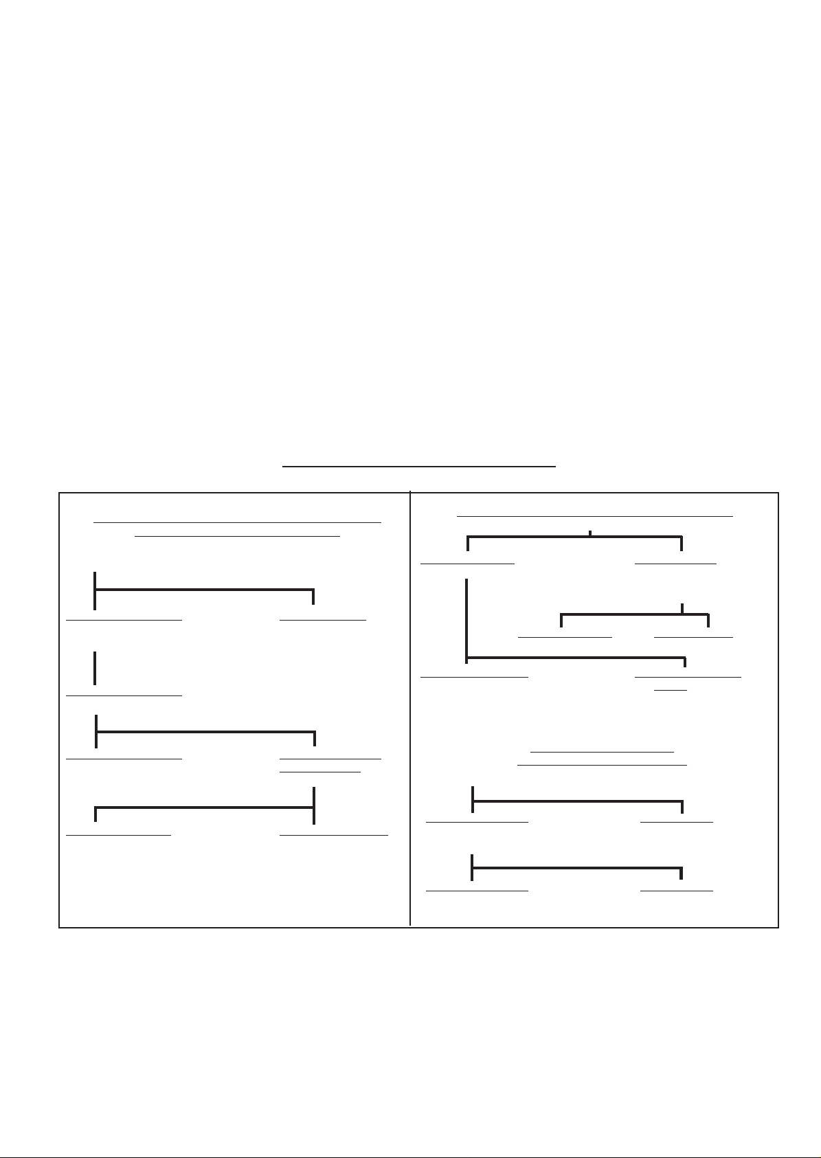
DEFECT DIAGNOSIS FLOW CHAR T
AIR CIRCULA TION FAN ON, BUT BURNER CYCLES BEFORE
REQUIRED COMFORT LEVEL IS REACHED
Disconnect Thermista-stat at terminals 3 & 4 and link terminal 3 to ‘TEST’
terminal. Do not link terminals 3 & 4.
Burner continues to cycle Burner remains on
Check air filter, return air path Thermista-stat defective.
and outlets for restrictions.
Burner continues to cycle
Link terminals 10 & 11 to bypass limit control.
Burner continues to cycle Burner runs and room
Replace electronics module. temperature rises
Check temperature rise.
Less than 60 degrees C More than 60 degrees C
Replace fan delay/overheat (limit) Replace electronics module.
control.
BURNER ON, BUT AIR CIRCULATION F AN NOT RUNNING
Check for 230 volts at fan terminals 14 & 15
No 230 volts detected 230 volts detected
Switch to ‘Summer Airflow’. Switch to ‘Summer Airflow’.
Check for 230 volts at energy
capacitor black leads.
No 230 volts detected 230 volts detected
Replace energy capacitor. Replace air circulation fan.
Air circulation fan runs Air circulation fan does
Replace fan delay/overheat not run
(limit control). Replace electronics module
BURNER ON CONTINUOUSL Y
(ROOM TEMPERATURE TOO HIGH)
Set Thermista-stat to ‘Summer Airflow’
Burner remains alight Burner goes out
Disconnect solenoid plug at Replace Thermista-stat.
multifunctional control.
Burner remains alight Burner goes out
Replace multifunctional control. Replace electronics module.
11
Page 12
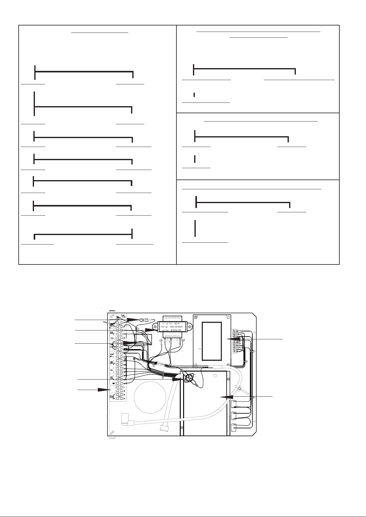
BURNER NOT OPERA TING
Check that the time control is on and Thermista-stat is calling for heat.
Check mains electrical supply.
Link terminals 5 & 7 (shorts out clock).
Disconnect Thermista-stat at terminals 3 & 4 and link terminal 3 to ‘TEST’
terminal. Do not link terminals 3 & 4.
ZZ757/9
AIR CIRCULATION F AN CONTINUES TO RUN OR CYCLES
Check that Thermista-stat is not set to ‘Summer Airflow’.
Disconnect Thermista-stat at terminals 3 & 4 and link terminal 3 to ‘TEST’
terminal.
Disconnect the fan delay/overheat (limit) control.
WHEN BURNER IS NOT ON
No response Burner lights
Link terminals 10 & 11. Reinstate connections at 3 & 4.
Check wiring to, or replace
Thermista-stat.
No response Burner lights
Check terminal 9 for 230 volts. Replace fan delay/overheat
(limit) control.
No 230 volts 230 volts detected
Check terminal C4 for 230 volts. Check wiring to, or replace
multifunctional control.
No 230 volts 230 volts detected
Check terminal 10 for 230 volts. Check wiring.
No 230 volts 230 volts detected
Check terminal 7 for 230 volts. Replace ignition module or
combustion air fan.
No 230 volts 230 volts detected
Check 230 volts at fuse, if OK Check transformer output
replace filter. voltages.
Voltages correct Voltages incorrect
Replace electronics module. Replace transformer.
Air circulation fan stops Air circulation fan continues to run
Replace fan delay/overheat Replace electronics module
(limit) control
Air circulation fan runs
Replace electronics module
COMBUSTION FAN RED OVERLOAD INDICA TOR ON
Defect in combustion fan circuit. Check connection to combustion fan.
Light stays on Light goes out
Replace combustion fan Defect cleared
Light stays on
Replace electronics module
AIR CIRCULA TION FAN RED OVERLOAD INDICA TOR FLASHING
Defect in air circulation fan circuit. Check connections to air circulation fan .
Light remains flashing Light goes out
Check fan is not obstructed. Defect cleared
Light remains flashing
Replace energy capacitor and/or fan
Fuse
Transformer
EMC Filter
Overheat cutout device
Terminal strip
Ignition module
Electronics control
module
Fig. 6, Electrical panel
12
Page 13
ZZ757/9
Flue
Spigot
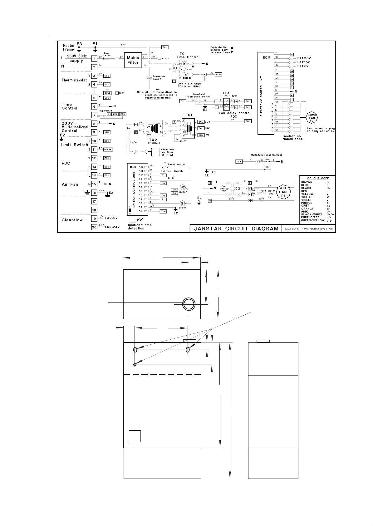
Fig. 7 JANSTAR functional flow circuit diagram
440
75
Rear face
190
285
Fixing holes
in rear face
44
268
40
122
600
830
Return air
plenum
Fig. 8 Principal dimensions (mm)
13
Warm air
plenum
Page 14

11. SHORT LIST OF SPARES
G.C. MAKER’S DESCRIPTION QTY
No No
E00 124 W800-0701000 Burner assembly 1
E00 125 W800-0774000 Burner metal fibre assembly 1
245 549 1000-1500840 Gasket - burner top plate 1
398 219 1000-0704560 Injector Bray Cat 15/850 1
245 530 W800-0300000 Heat exchanger assembly 1
245 533 1000-0704500 Multifunctional control valve 1
SIT Novamix 828
245 534 1000-0704490 Ignition/detection electrode 1
245 535 1000-0516440 Fan delay/overheat (limit) control 1
245 536 1000-0516400 Electronics module 1
245 537 1000-0516250 Transformer 1
245 525 1000-0515730 Transformer (Cleanflow filter) 1
173 118 1000-0516420 Ignition module 1
245 531 W800-0515005 Combustion air fan assembly 1
173 120 1000-0516200 Air circulation fan 1
245 538 1000-0504710 Capacitor 4µF 1
245 509 1000-0513820 Fuse T3.15A 1
245 514 1000-0515620 Thermista-stat 1
173 119 1000-0516830 Overheat cutout device 1
1000-0519500 EMC Filter 1
ZZ757/9
14
Page 15

Johnson and Starley prides itself on its ability to supply spare parts quickly and efficiently. If you have a problem in
obtaining a spare part, please contact Johnson and Starley Spares Department at the address below.
JOHNSON & STARLEY LTD.
Telephone: (01604) 762881 Rhosili Road,
Brackmills,
Telefax: (01604) 767408 Northampton NN4 7LZ
 Loading...