

Johnson & Starley HI-SPEC J32P, HI-SPEC J32RP Installation, Commissioning & Servicing Instructions
Page 1
These instructions are to be left with the User or adjacent to the Gas Meter
HI-SPEC J32P and HI-SPEC J32RP
WARM AIR HEATERS
with Conventional Control
INSTALLA TION, COMMISSIONING & SER VICING INSTRUCTIONS
G.C. No 42 451 07 HI-SPEC J32P
G.C. No 42 451 08 HI-SPEC J32RP
These appliances have been tested and certified by B G T echnology for use with PROP ANE gas G31.
Note: If a HIJAN 6P circulator is fitted, the relevant Installation, Commissioning and Servicing instructions provided with that
appliance must also be observed.
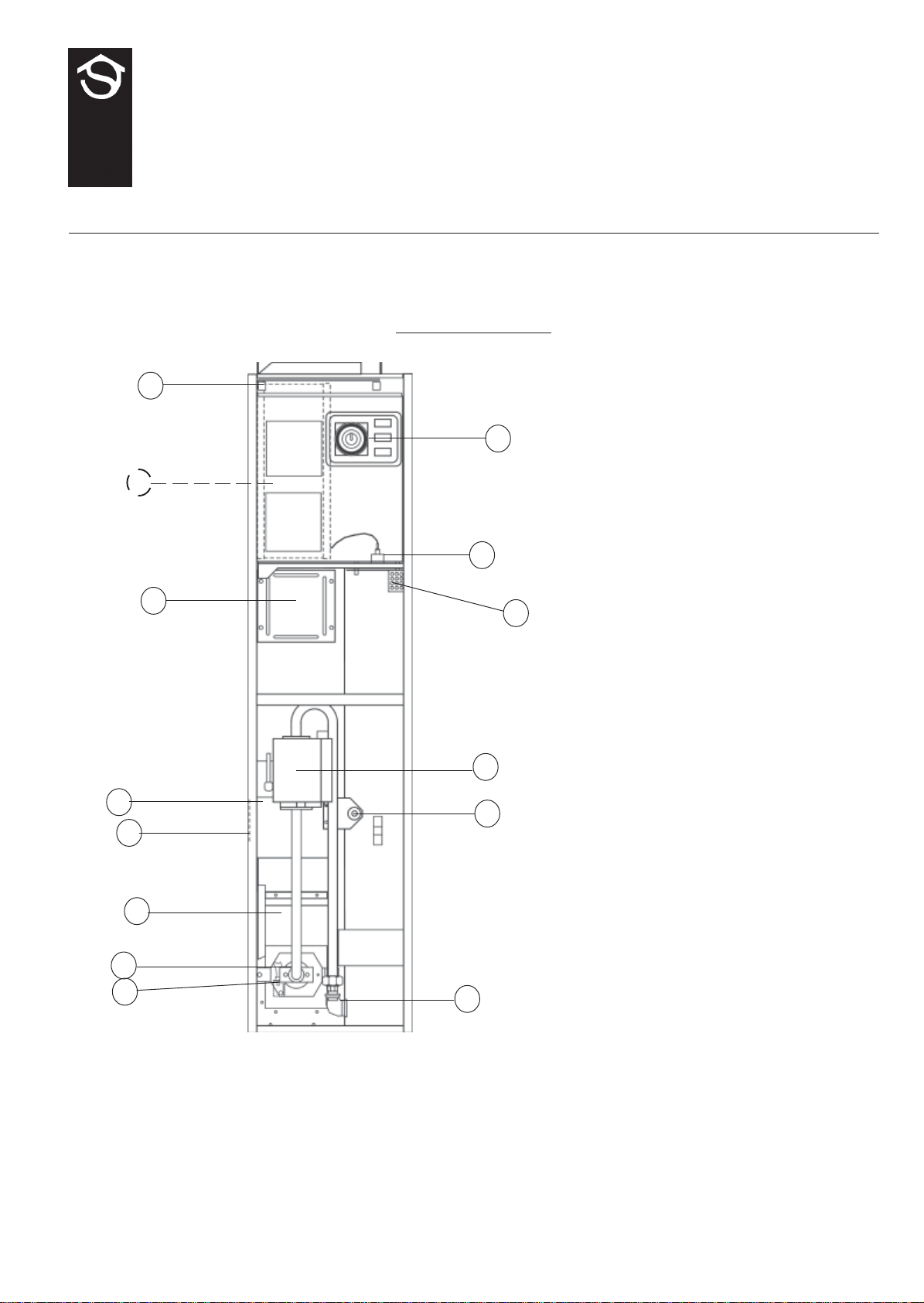
1. BRIEF DESCRIPTION
1
5
2
Publication No. ZZ 982/7
February 2007
13
1 Air Filter
3
7
4
11
9
8
10
14
6
12
2 Air circulating fan
3 Heat exchanger access cover
4 Data plate
5 Time control
6 Multifunctional control
7 Fan Delay Control/Limit Switch
8 Pilot burner
9 Burner Assembly
1 0 Gas connection
11 Heat shield
1 2 Piezo igniter unit
1 3 Spillage monitoring Device (TTB)
(Air heater)
1 4 Spillage monitoring Device (TTB)
(Water Heater)
Fig. 1
1. 1 HI-SPEC J32P is an open-flued, fan assisted downflow, ducted warm air heater, supplied with conventional control. A
HIJAN 6P circulator is available as an option. HI-SPEC J32RP, which has an integral rear rising duct is also available as
an option. A Spillage Monitoring Device (TTB) is fitted which senses the temperature in the draught diverter, and shuts
down the appliance when this temperature rises due to the presence of flue gases.
1. 2 The Air heater output is 8.30kW (29.88MJ/h, 28,320Btu/h) . “Summer air circulation” of unheated air is available by
manual selection (see User’s Instructions). HIJAN 6P output is 3.56kW (12.8MJ/h, 12,150Btu/h).
THIS APPLIANCE CONFORMS TO BS EN 55014
1
Page 2

Installation shall be in accordance with the current editions of:-
Building Standards (Scotland) (Consolidation) Regulations
Building Regulations
Gas Safety (Installation and Use) Regulations (as amended)
BS 7671 Institute of Electrical Engineers (I.E.E.) Wiring Regulations
BS 5482 Pt. 1 Domestic Butane- and Propane-gas-burning installations.
BS 5440 Pt. 1 (Flues for Gas Appliances)
BS 5440 Pt. 2 (Air Supply for Gas Appliances)
BS 5864 Installation of Gas Fired Ducted Air Heaters
British System Design Manual “Gas Fired Warm Air Heating”
Model and Local Authority Bye-laws
BS 5546 Installation of Domestic Hot Water Supplies.
IMPORT ANT : STA TUTE LAW DEFINES THA T ALL GAS APPLIANCES MUST BE INST ALLED BY COMPETENT PERSONS, (i.e. CORGI REGISTERED INST ALLERS) IN ACCORDANCE WITH THE GAS SAFETY (INST ALLATION AND
USE) REGULA TIONS (CURRENT EDITION). FAILURE TO COMPL Y WITH THESE REGULA TIONS MA Y LEAD TO
PROSECUTION.
2.
2.1 IMPOR TANT : If the heater is to be fitted to an existing base duct (warm air plenum), always ensure that installation is
carried out such that the rear left hand corner of the heater is aligned with the rear left hand corner of the base duct, so
that any overhang or blanking off will be at the front and/or right hand side. In any event, blanking plates must be
mechanically secured and all joints sealed.
2. 2 When the heater is fitted into a compartment, a minimum clearance from the compartment walls of 3mm at the
sides and rear, and 75mm (3 in) at the front must be left. Consideration should also be given to the space required for the
removal and replacement of the filter tray and the entry of the gas, water and electrical supplies. If gas and /or water
connections are made from a side entry , a minimum clearance of 75mm is required at that side.
2. 3 For service access, a minimum of 450mm (18ins) is required at the front of the heater . Space must also be allowed, in a
compartment installation, to permit the removal of the heater . The clearance between the appliance and the compartment
should be not less than 75mm (3 in). However, if clearances are less than 75mm, the internal surface of the compartment
must be lined with non-combustible material. The compartment must be of a fixed rigid structure.
2.4 In airing cupboard installations, the part used as the air heater compartment must comply with the relevant section of
BS5864 and must be completely separated by either a non-combustible partition or a perforated metal partition with the
perforations not exceeding 13mm (1/2in). The secondary flue must be a tight fit where it passes through the partition and
must be suitably protected (see BS5440:Part 1).
2.5 In free-standing installations, (see instructions packed with TC32 or TC32R T op Closure Kit), only one or two walls will be in
close proximity to the air heater; these must be non-combustible.
2.6 If the Air Heater is to be installed onto a combustible surface, a suitable base tray is required (BT32 for J32 model
appliances) is required. However, when a base duct is used, this provides suf ficient protection for combustible material and
no further insulation is required.
2.7 For Slot Fix applications (see instructions packed with the Slot Fix Kit), it is important to ensure that the draught diverter
relief is maintained on both sides of the application.
3. VENTILA TION AND COMBUSTION AIR
HEATER COMP ARTMENT AND CLEARANCES (See BS 5864)
3.1 The room or internal space in which the heater is installed requires a permanent air vent of minimum effective area
41cm2 (6in2). The air vent should be either direct to outside air or to an adjacent room or internal space (other than a
toilet or bathroom) that itself has an equivalent air vent direct to outside.
3. 2 Combustion air may be introduced, via a 100mm (4in) nominal bore pipe, connected to a return air duct or plenum from
a ventilated area and fitted with a lockable damper. The damper should be adjusted to control combustion airflow to
0.0099m3/s (21cfm), (i.e. 1.26m/s [250ft/min] velocity in a 100mm [4in] bore pipe). If this arrangement is used, a noncloseable warm air register MUST be provided in the same area as the front of the air heater or heater compartment if a
return air grille is not located in that area.
3. 3 When installed in a compartment, two permanent ventilation openings into the compartment are required, one at high
level and one at low level, both communicating either directly with outside air or with a ventilated room or space. The
minimum effective areas specified in Table 1 are related to the rated heat input of the Air Heater, and assuming that a
HIJAN 6P circulator is fitted.
3.4 If any room or area from which air is drawn for ventilation or combustion contains an extract fan, the permanent vents
must be sized to ensure that the operation of the appliance(s) at full rate is/are not adversely affected. A spillage test as
specified in sub-para 6.8 (Safety Checks) is carried out and any remedial work undertaken.
2
Page 3

VENTILA TED Low level grille 288cm2 (44in2)
FROM INSIDE
BUILDING High level grille 144cm2 (22in2)
VENTILA TED Low level grille 144cm2 (22in2)
FROM OUTSIDE
BUILDING High level grille 72cm2 (11in2)
T able 1: Minimum Effective Ar eas
4. DUCT SYSTEM
(See British Design Manual - Gas fired W arm Air Heating)
4.1 RETURN AIR
4.1.1 All return air shall be POSITIVEL Y ducted from outside the compartment to the top of the unit via a return air
duct, or if appropriate, using a J & S Side Return Air Kit, and mechanically secured. It is recommended that the
return air duct be not routed directly from the main living area, but from a convenient central area serving the
remainder of the dwelling.
4.1.2 The return air system should be constructed of fire-resistant material. The flue shall not be run through an area
serving as a return air path. It is extremely important that the correct size of return air grilles and ducting is used.
For heaters on maximum output the return air duct size should not be less than the equivalent of 250mm x 200mm
(10" x 8"). If flexible duct is used the duct diameter should not be less than 300mm (12") dia. The return air
grille should have a free area of not less than 860cm2 (137in2).
4.1.3 An adequate and unobstructed return air path is essential from areas not served by a directly ducted return and to
which warm air is delivered. All such rooms should be fitted with relief grilles which have a free area of
0.0088m2/kW (1in2/250Btu/h) of heat supplied to the room. The only exceptions are kitchens, bathrooms and
WC.’ s.
4.1.4 The return air duct should allow for ease of removal for access to the flue.
4.1.5 All duct work in the room or internal space in which the heater is installed shall be mechanically secured, and
sealed with ducting tape.
4.2 WARM DELIVERED AIR
4.2.1 All duct work, including riser ducts, should be fully insulated with 50mm (2in) fibreglass or similar . If short
extended duct runs are taken below floor level these should be similarly insulated, and in addition wrapped with a
sound vapour proof barrier, and protected from crushing.
4.2.2 The duct system should be carefully designed (as given in the guidelines in the British System Design Manual) to
suit the needs of its specific heating requirements and building layout. The type of duct system, (i.e. radial/
extended plenum/stepped) should be installed using the least number of fittings to minimise airflow resistance.
The base duct, which equalises the air pressure to supply ducts, shall be constructed to support the weight of the
heater, which shall be secured to the plenum with screws on at least two sides, and sealed using self-adhesive
foam strip, ducting tape or sealing compound. All ducting and blanking plates shall be mechanically secured and
sealed.
5. INSTALLATION REQUIREMENTS
Note: For circulator Installation Instructions, refer to the relevant instructions provided with the circulator.
5.1 FLUES (see British Standards BS 5440 Pt. 1 Flues)
5.1.1 All joints shall be soundly sealed.
5.1.2 The flue should be kept as short and warm as possible.
5.1.3 Sufficient support brackets shall be installed to bear the weight of the total flue system.
5.1.4 The spigot connection of the heater draught diverter will accept internally the spigot end of a non-asbestos flue
to BS 567 or twin wall metal flue to BS 715 of nominal 100mm (4in) diameter.
5.1.5 A split collar should be fitted to provide for flue maintenance or inspection.
5.1.6 The flue shall be in accordance with the Building Regulations and British Gas Materials and Installations
specification (3rd edition) with regard to clearance and shielding from combustible materials.
5.1.7 All materials shall be in accordance with Building Regulations requirements.
3
Page 4

5.1.8 The flue should run as vertically as possible. Horizontal runs should be avoided if at all possible and any
directional change should be as gentle as possible. If there is any doubt about the flue configuration, the
equivalent flue height should be determined (see 5.1.10).
5.1.9 If the appliance to be fitted is a replacement, the old appliance should be checked for signs of spillage prior to
commencement of the installation and appropriate action taken, (i.e. check flue system and renew as necessary).
5.1.10 It is recommended that at least 600mm of vertical flue should be provided above the appliance (for new
installations this shall be incorporated into the flue design). However, when carrying out replacement
installations, an existing flue system may be encountered, where the vertical flue above the appliance to the first
bend is less than 600mm. In the first instance, the installer must judge whether this distance can be achieved
practicably by some means. Where this is not practicable, the existing flue system may be used, providing there is
no evidence of spillage from the old appliance (see 5.1.9 above). Every effort must be made, however, to ensure
that the existing flue complies in every other way to BS 5440 Part 1, including the visual inspection, flue flow and
spillage test described in 4.3.2 of the above standard. Flue configurations may be assessed in terms of equivalent
vertical height - details are given below. For air heaters, the minimum equivalent vertical height is 1 metre. The
installer must make a judgement based on his knowledge and experience and the examination and testing
described above as to whether an existing flue system can be used.
Note: Ventilation of the compartment, room or internal space in which the appliance is to be installed must be checked
for compliance with the requirements of BS 5440 Part 2 ( Ref. Section 3 of these instructions) and upgraded as
necessary.
5.1.11 Calculation method for flue sizing: (from BS 5440: Part 1, Appendix A)
a. This appendix provides a procedure for estimating whether a given flue design is likely to ensure full
clearance of combustion products.
b. The procedure is based on calculating the ‘equivalent height’ of the flue under consideration, (i.e. that
height of the straight vertical circular flue pipe of specific size which will produce the same flow rate as
the flue under consideration). The equivalent height is calculated from the formula:
(K
+ Ko )
i
e
He = Ha x
(Ki + Ko)a - KeHa + Sum K
where:
He is the height of the equivalent flue;
Ha is the vertical height of the actual or proposed flue;
Ki is the inlet resistance of the flue;
Ko is the outlet resistance from the flue;
subscript e refers to the equivalent flue diameter;
subscript a refers to the actual or proposed flue diameter;
Ke is the resistance per unit length of the equivalent flue;
Sum K is the resistance (other than the inlet and outlet resistance) of the actual or proposed flue.
Note: K and Sum K are obtained from Table 2. Ko and Ki are obtained from Table 3.
c. Table 2 gives resistance factors for common flue components for use in the formula. Table 3 contains the
appropriate inlet and outlet flue resistances, ( the flue is likely to be satisfactory of its equivalent height
exceeds 1m).
4
Page 5
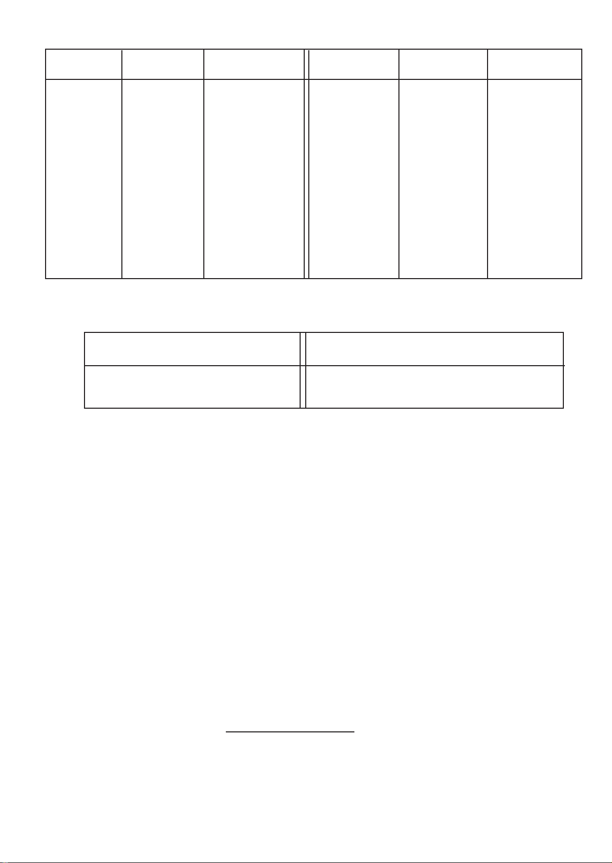
Component Internal Size Resistance Component Internal Size Resistance
(mm) Factor (mm) Factor
Flue Blocks 197 x 67 0.85 per meter 135O Bend 100 mm pipe 0.61 per
231 x 65 0.65 run 125 mm pipe 0.25 fitting
317 x 63 0.35 150 mm pipe 0.12
140 x 102 0.60 197 x 67 0.30
200 x 75 0.60 231 x 65 0.22
183 x 90 0.45 317 x 63 0.13
Pipe 100 0.78 Raking block Any 0.30 per block
125 0.25
150 0.12 Adaptor block Any 0.50
Chimney 213 x 213 0.02 Terminal 100 mm ridge 2.5
125 mm ridge 1.0
90O Bend 100 mm pipe 1.22 per 150 mm ridge 0.48
125 mm pipe 0.50 fitting 100 mm GCI 0 . 6
150 mm pipe 0.24 125 mm GCI 0.25
150 mm GCI 0.12
Table 2
Resistance factors for use in calculating equivalent heights
Appliance Inlet Flue Outlet
Resistance (Ki) Resistance (Ko)
100 mm dia spigot 2. 5 100 mm flue 2. 5
125 mm dia spigot 1. 0 125 mm flue 1. 0
150 mm dia spigot 0.48 150 mm flue 0.48
Inlet and outlet resistance
d. Worked Calculation Example:
A warm air unit with a 100 mm diameter flue spigot, fitted with a pre-fabricated flue system leading to a
ridge tile in the loft (refer Fig. 2):
From table 3:
Kia Inlet resistance of actual flue = 2.5
Koa Outlet resistance of actual flue = 2.5
Kie Inlet resistance of equivalent flue = 2.5
Koe Outlet resistance of the actual flue = 2.5
From table 2:
Other resistances of actual flue:
Terminal = 2.5
Pipe bend ( 2 x 0.61) = 1.22
Pipe (4 x 1m @ 0.78) = 3.12
(5 x 0.3m @ 0.78) = 1.17
Sum K = 8.01
Equivalent height :
From the formula
(2.5 + 2.5)
He = 6.2 x
(2.5 + 2.5) - (0.78 x 6.2) + 8.01
He = 3.793 This flue exceeds 1.0m equivalent height and is therefore satisfactory.
Table 3
5
Page 6
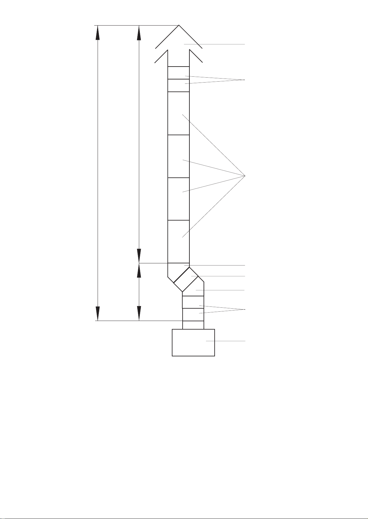
Ha = 6.2m
Ridge Terminal
2 x 300 mm lengths
100 mm dia flue pipe
4.6m
4 x 1000 mm lengths
O
45
bend
300 mm length
1.6m
45O bend
2 x 300 mm lengths
Flue spigot
Fig. 2
W orked example of equivalent flue height
5.1.12 Special consideration must be given to external flues with a view to prevention of condensation and weathering
problems.
5.1.13 An approved terminal should always be used; a ridge terminal or “GC1” terminal is specifically recommended.
The latter should be positioned in a free air space where it is not shielded by any structure. A minimum of 1m
(3ft.) from any vertical or inclined roof structure must be allowed for .
5.1.14 Where flue blocks are used, builders should ensure that no obstruction is created during erection. The installer
should ensure that the connection flue does not project beyond the internal wall of the flue blocks and that there
is provision for examination and servicing.
6
Page 7

5.1.15 Important: Before installing the appliance, carry out a visual check of the flue system as directed in the relevant
section of BS5440 Pt. 1, then check the flue performance as follows:a. Close all doors and windows in the room in which the appliance is to be installed.
b. Introduce some heat into the flue, using a blow torch or other means.
c. Carry out a flow visualisation check with a smoke pellet at the intended position for the appliance. Ensure
that there is discharge of smoke from the correct terminal only , and no spillage into the room.
Smoke coming out of other than the correct terminal only, or a down draught or ‘no flow’ condition,
indicates that the flue has failed the test, and the appliance shall not be connected until the defect has been
found and rectified, and the test satisfactorily completed.
5.2 ELECTRICAL
5.2.1 Mains.
a. The heater is supplied with mains cable (PVC sheathed, heat resisting to 85
o
C), 3-core Brown-BlueGreen/Yellow, 6A, 0.75mm2), connected to a terminal block and exiting through the heater at the right
hand top. The cable is suitable for a 230V 50Hz supply and shall be connected to the fixed wiring
using a double pole switched, fused spur, incorporating a protective earth link. The fuse fitted shall be
rated 5A to BS 1362 Connections shall be in accordance with the current edition of I.E.E Regulations BS
7671.
b. Fan Delay Controls and Limit Switch are not adjustable and are set as follows:
i . Fan Delay Control closes at 54OC± 4.5OC; opens at 40OC±3OC.
ii. Limit Switch opens at 80OC; closes at 60OC.
c. A 24V room thermostat (not supplied), that complies with BS 800 BS 3955 and BS 4201 is essential to
ensure close control of comfort conditions. An anticipator is located within the thermostat and is graded
in amps. The anticipator should be checked and adjusted to 0.2A.
5.2.2 Room Thermostat and its location.
a. The Room Thermostat should be located where there is free air circulation approx. 1.5m (5ft) from the
floor.
b. Avoid the following locations:-
i. In a room where temperature is greatly affected by the sun or any other heat source, e.g. radiant
fire, wall light fittings or TV set.
ii. Near an outside door or windows, or on an outside wall.
iii. Where affected by warm air ducts, diffusers, waste pipes or the heater itself.
iv. Where subject to vibration.
c. Connect Room thermostat wires to control panel terminals ‘7’ and ‘8’ (see Fig. 6 or 7).
5.3 GAS (See BS5864 and BS 6891)
5.3.1 An independent gas supply pipe from the meter is to be preferred wherever possible. When this is not possible,
the pipe must be capable of taking the complete input of the heater and all other gas appliances being served by
this same pipe. This supply should be suitably sized to conform to British Standards requirements of no more than
2.5 mbar (0.4in wg) pressure drop (See table of discharge in BS 5482 Part 1.).
5.3.2 The 1/2in union gas cock (supplied) must be fitted to the gas inlet of the heater for easy isolation during
servicing. The gas pipe should be so fitted and installed as to be durable, substantial and gas tight. To assist in
determining where a gas connection may not be tight, a leak detection fluid should be applied around the
connection. Under no circumstances should a flame be used to locate a gas leak. Gas entry to the air heater is
through either side to a Rc1/2 (1/2in BSP. external [taper] thread).
6. COMMISSIONING
6.1 PREPARATION:
6.1.1 Ensure that:
a. Gas and Electrical supplies are OFF.
b. Filter, fan and fan compartments are free from obstructions.
c. All registers or grilles are open and conform to design specifications.
d. Return, relief and ventilation air installations are adequate.
7
Page 8
6.2 SYSTEM BALANCING:
6.2.1 Set the Air Heater electrical supply ON.
6.2.2 Set the SUMMER AIRFLOW switch to ‘1’.
6.2.3 Balance the system to provide the required volume proportions at the warm air outlets.
Note: If the system includes ceiling diffusers, the air through these should be NOT LESS THAN 1.5m/s (300ft/min), except
for very small rooms, (i.e. bathrooms etc.). Outlet faces may require partial blanking in order to achieve this.
6.2.4 Set the SUMMER AIRFLOW switch to ‘0’.
6.3 IGNITION OF PILOT AND MAIN BURNERS:
W ARNING: If the pilot light is extinguished either intentionally or unintentionally , no attempt should be made to
relight the gas for a minimum of 3 minutes. Ensure that the electrical supply , T ime Control and Selector switches are set to
‘OFF’.
6.3.1 Set the room thermostat to its lowest setting.
6.3.2 On the Multifunctional Control, remove the Inlet Pressure test point cover, and a fit pressure test gauge (refer fig.
4).
6.3.3 Turn the heater Gas supply ON, test for gas soundness and purge the whole gas pipe as described in BS 5482
Part 1.
6.3.4 Referring to Fig .4, press and hold the OPERA TING CONTROL, and whilst observing the Pilot Burner , repeatedly
press the Piezo igniter button until the Pilot Burner ignites.
6.3.5 After 20 seconds release the OPERATING CONTROL and let it spring out; ensure that the Pilot Burner remains
alight. If the Pilot Burner extinguishes, rotate the OPERA TING CONTROL clockwise to the ‘z’ position and
ensure that the OPERATING CONTROL is fully reset. Wait three minutes and repeat steps 6.2.4 and 6.2.5 until
the Pilot burner remains alight.
6.3.6 With the Pilot burner lit, depress the OPERATING CONTROL and turn it to the position indicated by the flame
symbol.
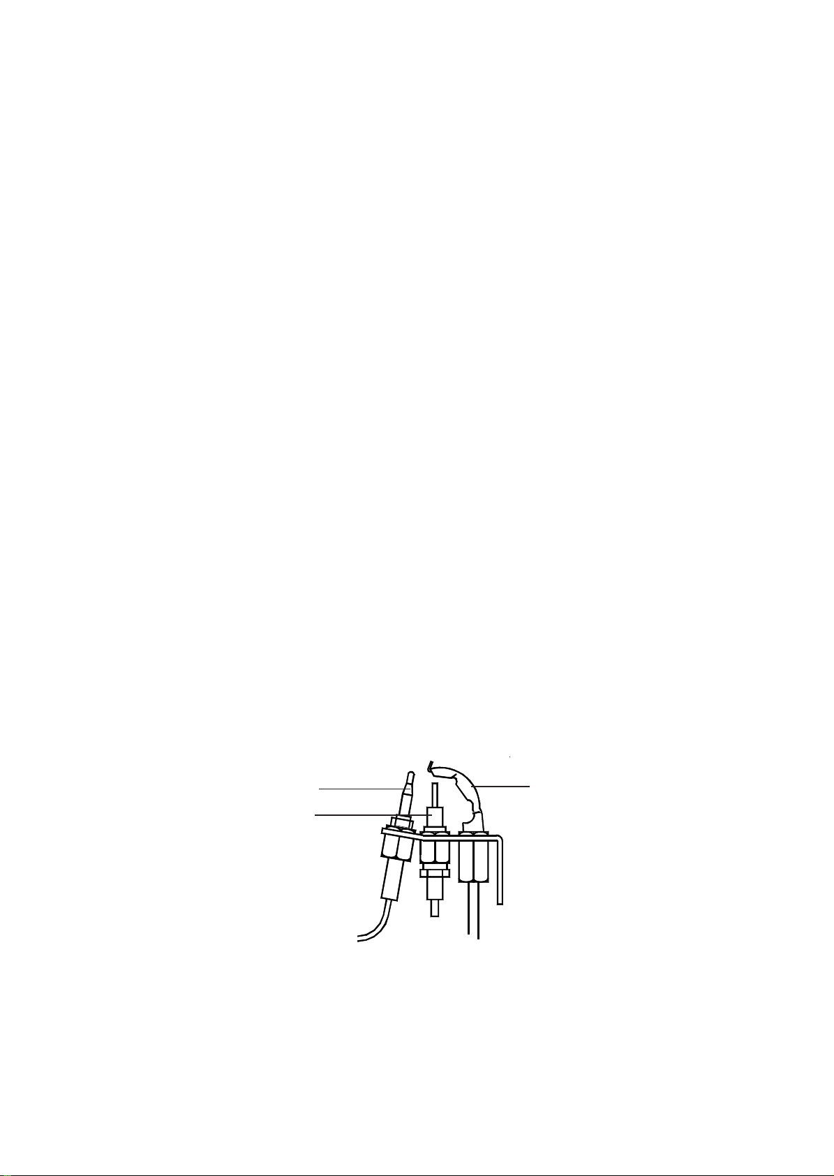
6.3.7 Ensure that the pilot flame envelops thermocouple tip (refer Fig. 3).
6.3.8 Set the Heater Electricity supply ON.
6.3.9 Set the Time control to the required Heating On periods.
6.3.10 Set the Selector switch to ‘TIMED’.
6.3.11 Set the room thermostat to MAXIMUM.
6.3.12 Ensure that the main burner has now ignited.
6.3.13 Test for gas leakage at the supply, Multifunctional control, Pilot and Main burners using proprietary detection
fluid, sealing any leaks found.
6.3.14 Allow heater to operate for a minimum of 15 minutes to ensure stability.
Thermocouple
Electrode
Pilot Burner
Fig. 3
PILOT BURNER ASSEMBLY
8
Page 9
6.4 MAIN BURNER PRESSURE TEST:
6.4 MAIN BURNER PRESSURE TEST AND TEMPERA TURE RISE CHECK:
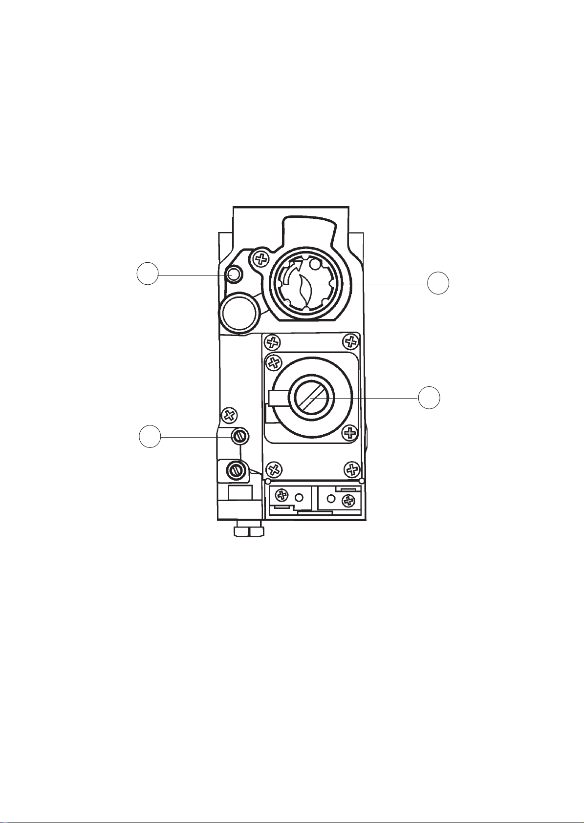
6.4.1 Referring to Table 4 and Fig. 4 below, ensure that the pressure test gauge indicates correct pressure, adjusting the
6.4.1 Referring to Table 4 ensure that the pressure test gauge indicates the correct burner pressure, a low pressure
supply pressure if required.
indicates a regulator fault or low cylinder pressure.
6.5 EXTINGUISHING OF BURNERS:
6.5.1 On the Multifunctional Control, rotate the OPERA TING CONTROL clockwise to the ‘z’ position and ensure that
6.5.2 On the Multifunctional Control, remove the pressure test gauge and refit the Inlet Pressure test point cover, and
6.4.2 Check that the temperature rise across heater is between 45oC - 55oC, setting the fan speed accordingly by alteration
6.6 TEMPERA TURE RISE CHECKS:
6.6.1 Ignite the Pilot and Main Burners and allow 15 minutes for stability before continuing.
6.6.2 With the Main Burner operating continuously , check that the temperature rise across heater is between 45oC -
Note: T apping 1 = 150V, T apping 2 = 170V, Tapping 3 = 190V, T apping 4 = 210v and T apping 5 = 230V.
a. At the Multifunctional control:
i . Remove the Burner Pressure Adjuster cover.
the OPERA TING CONTROL fully resets, and both the Pilot and Main Burners are extinguished.
check for gas soundness.
of the voltage selection at the tap changer on the control panel, (decrease voltage to decrease fan speed thus
increase temperature).
55oC, adjusting the fan speed at the control panel voltage selector, (decrease voltage selection to decrease fan
speed).
Note: T apping 1 = 210V, tapping 2 = 175V , tapping 3 = 150V, tapping 4 = 120V and tapping 5 = 100V.
ii. Set the Burner Pressure Adjuster to provide a pressure test gauge indication for the correct burner
pressure as detailed in T able 4.
iii. Refit the Burner Pressure Adjuster cover.
2
1
4
3
1. Operating control
2. Inlet Pressure test point
3. Outlet Pressure test point
4. Burner Pressure adjuster
Fig. 4
MUL TIFUNCTIONAL CONTROL
6.7 AUTOMA TIC CONTROLS CHECK
.5 EXTINGUISHING OF PILOT AND MAIN BURNERS:
6.7.1 Set the TIME CONTROL to ‘ON’.
6.5.1 On the Multifunctional Control, rotate the OPERA TING CONTROL clockwise to the ‘O’ position and ensure that
6.7.2 Set the room thermostat slowly clockwise until the Main Burner ignites.
6.7.3 Ensure that the fan starts to operate after a short period (approx. 1-2 minutes).
6.5.2 On the Multifunctional Control, remove the pressure test gauge and secure the Pressure test point screw.
6.7.4 When the temperature reaches the control setting, ensure that the Main Burner extinguishes followed by the fan
6.6 AUTOMA TIC CONTROLS CHECK
6.6.1 Ignite the Pilot burner .
6.7.5 When the temperature falls below the control setting, ensure that the Main Burner re-ignites followed by fan
6.6.2 Set the TIME CONTROL to ‘ON’.
6.6.3 Set the Room Thermostat slowly clockwise until the Main Burner ignites.
the OPERA TING CONTROL fully resets, and both Pilot and Main Burners are extinguished.
switching off after a short period.
operation.
6.6.4 Ensure that the fan starts to operate after a short period.
6.6.5 When the temperature reaches the control setting, check that the Main Burner extinguishes followed by the fan
switching off after a short period.
6.6.6 When the temperature falls below the control setting, ensure that the Main Burner re-ignites followed by fan
operation.
9
9
Page 10

6.8 SAFETY CHECKS:
6.8.1 Check for gas soundness within the appliance.
6.8.2 Spillage test: Carry out a full spillage test as follows, and ensure that the flue operates effectively with all doors
closed and any extractor fans in operation.
NOTE: If an extractor fan is situated in an adjoining or adjacent room, carry out the spillage test with the interconnecting
doors open.
If the draught diverter is accessible:
a. Introduce smoke into the draught diverter adjacent to an exit from the heat exchanger, by means of a
smoke match or puffer.
b. Ensure that there is no spillage present (indicated by displacement of smoke downwards and out of the
draught diverter.
If the Draught Diverter is not accessible:
a. Introduce smoke, by means of part of a smoke pellet on a non-combustible support, into the heat
exchanger.
b. Extinguish the Main and Pilot burners.
c. Ensure that there is no spillage evident by visually observing the draught diverter location on the air
heater.
d. If spillage is evident, further investigation and rectification is required before re-testing the appliance.
e. Repeat spillage tests but with the fan running, or Summer Airflow switch set to ON.
W ARNING: The appliance shall not be left connected to the gas supply unless it has successfully passed
the above spillage test.
6.8.3 Turn OFF the gas supply at the service cock and ensure that the Multifunctional Control fail-safe operates within
60 secs (indicated by loud click from Multifunctional Control).
6.8.4 Turn gas supply ON at service cock.
6.8.5 Switch the appliance electrical supply OFF .
6.8.6 Disconnect the Air Circulation Fan at the flying lead socket.
6.8.7 Switch the appliance electrical supply ON.
6.8.8 Ignite the Pilot and Main Burners as detailed in 6.3.1 to 6.3.5.
6.8.9 Ensure that the Limit Switch operates, indicated by the main burner extinguishing, within 120 and 180 seconds.
6.8.10 Switch the appliance electrical supply OFF .
6.8.11 Reconnect the Air Circulation Fan.
6.8.12 Switch the appliance electrical supply ON.
6.8.13 Ensure that the Main Burner re-ignites when the appliance temperature reduces, (note: with the Air Circulation Fan
disconnected, there may be some delay before the Main Burner re-ignites).
kW MJ/h Btu/h
INPUT 11.1 40.0 38,000
OUTPUT 8.30 29.88 28,320
Gas rate 0.418 m3/h
Propane G31 (14.77 ft3/h)
Burner setting 33 m bar ( 13.2 i n wg)
pressure (hot)
Main Injector Br a y 1 .7 8 m m
T able 4
Main Burner Pressure Settings
10
Page 11

mbar in.wg.
0.50 0.20
0.375 0.15
100V
120V
150V
175V
210V
0.25 0.10
RESISTANCE EXTERNAL TO HEA TER
0.125 0.05
2 00 250 300 350 400 ft3/min
0.09 0.12 0.14 0.17 0.19 m3/sec
AIR VOLUME
T able 5
Fan Performance Curve
7. INSTRUCTIONS FOR USERS
7.1 If the building is unoccupied, ensure that the Instructions for User are left taped to the air heater for the User, and
Installation Instructions are left at or near the air heater for use on future service calls.
7.2 If the building is occupied, hand the User Instructions over and ensure the User understands:
7.2.1 How to ignite the pilot and burner .
7.2.2 How to operate the room thermostat, time and heater ON/OFF switch and summer air circulation switch, and that the
time control must be reset following a power failure.
7.2.3 How to extinguish the pilot and main burner at the Multifunctional control, and switch off electrical supply to the
heater.
7.2.4 How to remove, clean and refit the air filter and at what intervals (i.e. fortnightly , or for new houses, weekly).
7.2.5 How to control the heating system by opening and closing warm air outlets.
7.2.6 How to obtain summer air circulation.
7.2.7 That the air grilles on the heater or heater compartment; grilles and ventilators in the walls, windows or doors of the
building must not be obstructed.
7.2.8 Tha t the heater must be serviced at least once a year by a competent person to ensure efficient and safe operation.
7.2.9 That the red instructions for safe use have been pointed out and understood.
7.2.10 That expert help must be obtained if persistent failure of the pilot burner occurs.
8. MAINTENANCE
IMPORT AN T: Ensur e gas and electricity supplies are isolated before commencing any maintenance or replacement of components. After completion of any maintenance, always test for gas soundness and carry out a complete functional test of the appliance in accordance with Commissioning Instructions at Sect 6.1 to 6.8 inclusive.
8.1 ROUTINE MAINTENANCE:
8.1.1 Operate the appliance and check for the correct function of the burner and controls.
8.1.2 Turn OFF the gas and electrical supplies to the appliance.
8.1.3 Remove the air heater front panel.
8.1.4 Remove and check the return air filter/cleaner for cleanliness, remove and clean the Air Circulation fan as
detailed in para 8.7.
8.1.5 Remove the Burner and Controls Assembly as detailed in para 8.2. Inspect and clean the main burner and injector
as necessary . Examine the main burner for cracks, including hairline cracks, exchanging the burner as necessary .
8.1.6 Inspect and clear the pilot burner orifice.
8.1.7 Clean the heat exchanger flueways by thoroughly brushing from above and below .
8.1.8 By viewing through the Fan Aperture, and using a torch or similar , examine the heat exchanger externally for signs
of cracks or holes, particularly around welded joints.
11
Page 12

8.1.9 Using a torch or similar, introduce a light source into the heat exchanger burner aperture and upper access port,
and again examine the heat exchanger for signs of cracks or holes, particularly around welded joints, whilst again
viewing through the Fan Aperture.
8.1.10 Refit the Air Circulation fan, Burner and Controls Assembly , and air filter/air cleaner.
8.1.11 Light the appliance and note the main burner flame profile. If the flame profile is affected when the Air
Circulation fan switches on, check for any air leaks between the air heater and the base plenum, paying particular
attention to heaters with rear draught diverters. Rectify any air leaks before continuing with this procedure.
8.1.12 Allow the air heater to operate for approximately 15 minutes to ensure stability , and with the main burner lit,
ensure that the operation of Air Circulation fan does not af fect the main burner flame profile.
8.2 BURNER AND CONTROL ASSEMBLY REMOV AL:
8.2.1 Ensure that the Gas and Electrical supplies are switched OFF
8.2.2 Remove the appliance louvre door.
8.2.3 Disconnect the igniter at the Piezo unit.
8.2.4 Disconnect the Multifunctional Control electrical connections.
8.2.5 Disconnect the gas supply by breaking the union at the input side of the Multifunctional Control, and water
heater union (if applicable).
8.2.6 Whilst supporting the Burner and Control Assembly , remove 3 x Burner Assembly fixing screws and withdraw the
Burner and Control Assembly
8.2.7 Refit the Burner and Control Assembly in reverse order .
8.3 BURNER AND CONTROL ASSEMBL Y CLEANING:
8.3.1 Remove the Burner and Controls Assembly as detailed in 8.2.
8.3.2 Disconnect the Pilot Feed Pipe and Thermocouple from the Multifunctional Control.
8.3.3 Release the single screw, nut and washer securing the Pilot Assembly to the Burner and Controls Assembly, and
remove the Pilot Assembly .
8.3.4 Release the 2 screws, nuts and washers securing the Main Burner to the mounting bracket, and remove the Main
Burner.
8.3.5 Clean burner thoroughly both inside and out with a soft brush. DO NOT ENLARGE, DISTORT OR DAMAGE
BURNER HOLES.
8.3.6 Reassemble in reverse order.
8.4 PILOT BURNER, THERMOCOUPLE AND ELECTRODE, REMOVAL AND REPLACEMENT :
8.4.1 Remove the Burner and Controls Assembly as detailed in 8.2
8.4.2 Disconnect the Igniter lead from the Electrode.
8.4.3 Disconnect the Thermocouple from the Multifunctional Control, taking care to avoid damage to the thermocouple
capillary.
8.4.4 Release the Pilot Feed Pipe from the Multifunctional Control.
8.4.5 Release the single screw, nut and washer securing the Pilot Assembly to the Burner and Controls Assembly, and
remove the Pilot Assembly .
8.4.6 Release the Thermocouple securing nut from the Pilot Burner Assembly and withdraw the Thermocouple, taking
care to avoid damage to the Thermocouple capillary .
8.4.7 Release the Electrode securing nut from the Pilot Burner Assembly and withdraw the Electrode.
8.4.8 Release the Pilot Feed Pipe securing nut from the Pilot Burner Assembly and withdraw the Pilot Feed Pipe and
Pilot Injector from the Pilot Burner assembly, and disconnect the Pilot Injector from Pilot Feed Pipe hook.
8.4.9 Release the 2 screws securing the Pilot Burner Bracket to the Pilot Mounting bracket, and remove the Pilot
Burner Bracket.
8.4.10 Refitting or replacement is in reverse order.
NOTE: When refitting or replacing the Thermocouple, tighten only to FINGER TIGHT + 1 FLA T.
12
Page 13

8.5 MULTIFUNCTIONAL CONTROL REMOVAL:
8.5.1 Remove the Burner and Controls Assembly as detailed in 8.2
8.5.2 Disconnect the Thermocouple at the Multifunctional Control, avoiding damage to the capillary .
8.5.3 Disconnect the Pilot Feed Pipe from the Multifunctional Control.
8.5.4 Disconnect the Multifunctional Control input and output supply feeds.
8.5.5 Refitting or replacement is in reverse order.
NOTE: When refitting or replacing the Multifunctional Control, the ‘O’ ring seal is to be replaced.
8.6 PIEZO UNIT REMOV AL:
8.6.1 Disconnect the 2 conductors from Piezo unit.
8.6.2 Release the retaining nut and remove the Piezo unit from its mounting bracket.
8.6.3 Refitting or replacement is in reverse order.
8.7 AIR CIRCULA TING F AN, REMOVAL AND CLEANING:
8.7.1 Ensure that the electrical supply is isolated.
8.7.2 Remove the appliance louvre door, release the 2 x securing screws and hinge down the fan chamber door.
8.7.3 Disconnect the fan flying leads from the Fan Assembly.
8.7.4 Release the Fan Assembly securing screw and withdraw the Fan Assembly from the Heater cabinet, avoiding
damage to the fan blades.
8.7.5 Remove all dust from both the impeller and motor, taking care to not disturb the balance of the fan.
8.7.6 Refitting or replacement is in reverse order.
8.8 ELECTRICAL ASSEMBLY REMOV AL:
8.8.1 Ensure that the electrical supply is isolated.
8.8.2 Remove the appliance louvre door, release the 2 x securing screws and hinge down the fan chamber door.
8.8.3 Disconnect the following:
a. Air circulation fan flying leads from the Fan assembly ,
b. 230V mains ‘L’, ‘N’ and ‘E’ from connection block terminals ‘1’ and ‘2’, and Earth stud respectively,
c. Room thermostat connections from connection block terminals ‘7’ and ‘8’,
d. Limit Switch from connection block terminals ‘13’ and ‘14’,
e. Fan Delay Control from connection block terminals ‘18’ and ‘17’,
f. Multifunctional Control from connection block terminals ‘16 (N) and ‘15’ (L),
g. Water heater from connection block terminals ‘10’ (L) and ‘9’ (N),
h. Water Pump from connection block terminals ‘12’ (L) and ‘11’ (N),
i. Cleanflow from connection block terminals ‘19’ (24V) and ‘20’ (0V),
j. Earth lead from the fan chamber floor,
8.8.4 Disconnect 2 x Spillage monitoring device connections from the terminal block on the fan compartment
diaphragm.
8.8.5 Release the 2 x hinge pins and withdraw the Electrical Assembly , releasing wiring from cable clamps and
grommets as required..
8.8.6 Refitting or replacement is in reverse order.
8.9 TRANSFORMER REMOVAL:
8.9.1 Ensure that the electrical supply is isolated.
8.9.2 Remove the appliance louvre door, release the 2 x securing screws and hinge down the fan chamber door.
8.9.3 Disconnect the conductors from the large Transformer.
8.9.4 Release 2 x screws and nuts securing Transformer to Electrical assembly , and remove Transformer..
8.9.5 Refitting or replacement is in reverse order.
13
Page 14

8.10 TIME CONTROL and SWITCH REMOV AL:
8.10.1 Ensure that the electrical supply is isolated.
8.10.2 Remove the appliance louvre door, release the 2 x securing screws and hinge down the fan chamber door.
Time Control removal:
8.10.3 Disconnect conductors ‘C1’, ‘C2’, ‘C3’ and ‘C5’ from the Time control.
8.10.4 Release the 2 x fixing screws, and withdraw the Time control.
8.10.5 Refitting or replacement is in reverse order.
8.10.6 Set the Time Control to the required ON and OFF times.
8.10.7 Set the Time Control to the correct time.
Switch removal:
8.10.8 Disconnect the conductors from the switch terminals.
8.10.9 Depress the retaining clips and press the switch out of the fascia panel.
8.10.10 Refitting or replacement is in reverse order.
W ARNING: The fascia panel is held in place by push fit retainers which must be r emoved with caution to avoid
causing damage to the support pins. Removal of the fascia is not advised unless it is intended to be replaced.
8.11 FAN DELA Y CONTROL/LIMIT SWITCH REMOVAL:
8.11.1 Ensure that the electrical supply is isolated.
8.11.2 Remove the appliance louvre door, release the 2 x securing screws and hinge down the fan chamber door.
8.11.3 Disconnect the following at the Electrical panel:
a. Limit Switch from connection block terminals ‘13’ and ‘14’,
b. Fan Delay Control from connection block terminals ‘18’ and ‘17’,
c. Earth connection from common earth stud.
8.11.4 Release 2 x 4mm screws securing Limit Switch mounting plate, and withdraw the control from the appliance by
drawing the conductors through the grommet in the fan chamber floor.
8.11.5 Refitting or replacement is in reverse order.
8.12 SPILLAGE MONITORING DEVICE (TTB) REMOV AL:
8.12.1 Ensure that the electrical supply is isolated.
8.12.2 Remove the appliance louvre door, release the 2 x securing screws and hinge down the fan chamber door.
8.12.3 Disconnect the TTB from its conductors.
8.12.4 Release 2 x screws securing the TTB Bracket to the fan chamber floor, and withdraw TTB Bracket.
8.12.5 Refitting or replacement is in reverse order.
8.13 HEA T EXCHANGER ACCESS:
8.13.1 Ensure that the electrical supply is isolated.
8.13.2 Remove the appliance louvre door.
8.13.3 Remove the Burner and Controls Assembly as detailed in sect 8.2.
8.13.4 Release the 4 screws securing the combustion chamber heat shield, and withdraw the heat shield.
8.13.5 Release the 4 screws securing the top access cover plate, and withdraw the cover plate and gasket
8.13.6 Release the 4 screws securing the heat exchanger top sealing plate, and withdraw the sealing plate and gasket.
8.13.7 Reassembly is in reverse order.
NOTE: When reassembling, ensure that the gaskets ar e soundly sealed, and fully re-commission the heater .
14
Page 15

9. DEFECT DIAGNOSIS
9.1 IMPOR T ANT : If an electrical defect occurs after installation of the appliance; preliminary earth continuity ,
polarity, and resistance to earth checks should be carried out with a multimeter. On completion of any
maintenance/fault-finding task that has required the breaking and remaking of electrical connections, then
checks of continuity, polarity, and resistance to earth must be repeated.
9.2 WARNING: When purging or checking gas supplies, ensure that the ventilation to the room or cupboard is adequate, and
that all naked lights are extinguished.
SYMPTOM POSSIBLE CAUSE REMEDY
a. Pilot will not light. i. No gas supply to heater. Check for gas at inlet pressure test
point on Multifunctional Control.
ii. Gas supply pipe not purged. Purge gas supply pipe in accordance
with BS 6891.
iii Pilot orifice restricted. Clear pilot orifice or replace pilot injector.
iv. Piezo system faulty. Check igniter, lead, and electrode.
v. Excessive gas supply pressure. Check that mains gas pressure is 37mbar,
and reduce if necessary.
b. Pilot lights but goes i. Connection between thermo- Check connection is secure.
out on releasing STAR T couple and Multifunctional
button during initial Control not secure.
light-up, or after
normal operation. ii . Faulty Multifunctional Replace Multifunctional Control.
Control.
iii. Faulty Thermocouple. Replace Thermocouple.
c. Main burner opera- i. Gas rate or burner pressure Check gas rate and burner pressure
ting intermittently setting high. setting.
with fan running.
ii. Temperature rise excessive. Adjust fan speed or gas rate accordingly.
iii. Air filter or return air path Check filter is clean and air path is clear.
restricted.
iv. Excessive number of outlets Open additional outlets.
closed.
v . Spillage of flue gases. Carry out spillage test and rectify.
vi. Spillage monitor device (TTB) Replace Spillage device (TTB)
faulty.
d. Pilot alight but main i. Mains electrical supply not Check mains supply.
burner not igniting. connected to heater.
i i . Controls not demanding heat Check that time control and
room thermostat are operating correctly.
iii. T3.15A fuse failed. Replace. If failure occurs again, check
wiring for short circuits.
iv. Loose connection to room thermo- Check connections.
stat, Limit Switch, gas control lead,
time control, or transformer.
v. 230V/24V transformer failure. Check 24V side with test meter, if voltage
missing, replace transformer.
vi. Faulty relay module Check 230V at white wire from switch S5
vii. Multifunctional Control faulty. Replace Multifunctional Control.
viii.Limit Switch faulty. Short circuit control and replace Fan Delay/
Limit control if necessary.
i x. Room thermostat or external Fit temporary loop in heater thermostat
wiring faulty. socket. If heater ignites, external circuit
or room thermostat is faulty.
x. Spillage device faulty Check Spillage device and wiring for open
circuit.
15
Page 16

e. Main burner lights i . Loose electrical connection Check connections.
but fan fails to run at fan control.
after approx. 3 min.
i i . Fan delay control faulty . Replace Fan Delay/Limit Switch.
iii. Faulty fan assembly. Replace, taking care not to damage
impeller.
iv. Burner pressure setting incorrect. Adjust pressure as necessary.
g. Main burner opera- i. Gas rate or burner pressure Check gas rate and burner pressure
ting with intermittent setting too low. setting.
fan operation.
i i. Fan delay control faulty Replace Fan Delay/Limit control.
h. Noisy operation. i. Gas pressure too high. Check burner pressure setting.
ii. Noisy fan motor . Replace fan assembly.
iii. Fan speed setting too high. Adjust fan speed.
i . Fan runs for excessive i. Fan delay control faulty. Replace Fan Delay/Limit control.
period or operates
intermittently after
main burner shuts down.
16
Page 17
g/y
to A
br
ANCILLARIES
Link Cont. 230v
Earth
230v
1
50Hz
Mains
Supply
Continuous.
br
b
NL
Timed
230v
N
A
1
Fuse
br
T3.15A
br
b
br
b
gy
When
C5
w
AH
r
L
N
fitted
S1
S2
SAC
TX2
S3
0V
24V
y
OFF
ON
6VA Double Bobbin
v
or
or
Wire Colour Code
blue ----b black -----bk red ----r
black/white ---bk/w
purple/red ---p/r
brown ---br violet ---v
grey ----gy white ----w
orange ---or yellow ----y green/yellow---g/y
Issue 07
TX1
br
230v
Voltage Selector
b
Auto Transformer
N
M
C1
C2
br
b
fitted
When
br
b
b
gy
S8
r
WH
nc
C3
gy
w
S7
S4
Timed
S5
Off
S6
Cont.
S9
gy
Earth
Th/Stat.
Test
b
230v
230v
230v
230v
Water
Water
Limit
Multi-
functional
Fan
Heater
pump
LNLN
control
GE T
control
NL
bk
Delay
Control
24V
Cleanflow
0V
brb
br
br
bbrr
bk
r
bk
2
p/r
87 654 32
r
b
r
br
br
b
bk
or
bk
20 19 18 17 16 15 14 13 12 11 10 9
bk
y
b
b
b
r
Butt
w
Conn.
br
p/r
Relay
Module
r
Comm.
24v
y
T500mA
Fuse
or
FROST
See note *
r Sleeve
ANTI-HYPO.
TTB
r
or
p/r
bk
bk
g/y
Note-: *
w
N/O
N/C
24v
If Superjan fitted remove
0v
terml. 10 & 12
red wire link between
v
bk
y
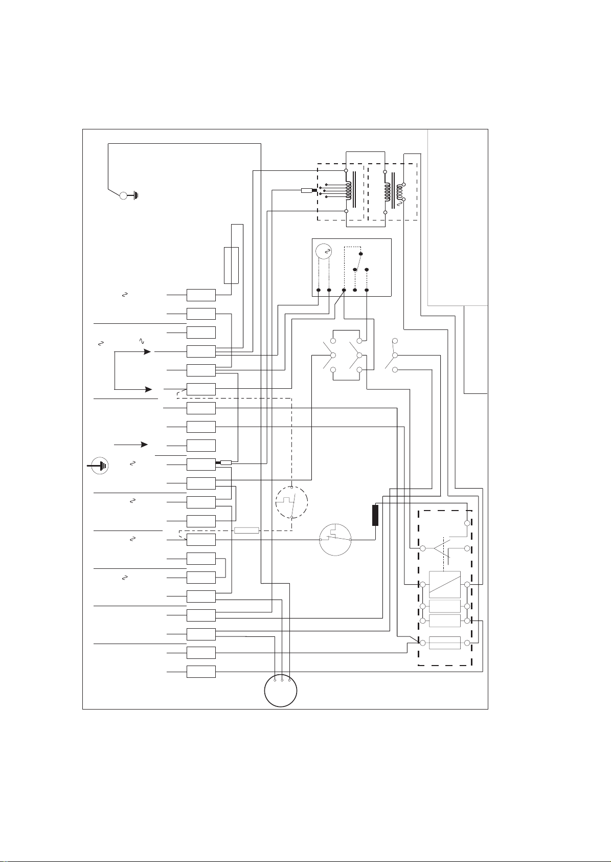
Fig. 5, CIRCUIT DIAGRAM
FAN
17
Page 18
13
18
14
17
N
N
N
N
N
230V 50Hz
S5
T
1
0
L
Fan
N
n/o
N
N
Supply
Timed
230V
Cont.
Room Thermostat
Water Heater
(Optional)
Water Pump
(Optional)
Limit Switch
Multi-functional
Control 230V
Fan Delay
Control
24V
Cleanflow
(Optional)
Park conns when no
clock fitted or for
external prog.
230V
NO CLOCK
OPTION
T3.15A
br
1
L
FUSE
230V
2
N
Continuous
3
4
5
N
A
6
br
4
br
Link
6
7
C1
C2
C3
C6
S8
Park S8 when no
water htr. or
for ext. prog.
C1
br
C3
gy
CLOCK
gy
N
230V Cont.
AH(S5)
Timed
WH
Timed
M
C4
SW
C5
C2
EXTERNAL PROG.
b
S4
w
AIR
HTR.
S6
8
L
0V
Voltage
Selector
TX1
TX2
24V
WATE R
HTR.
S9
S7
N
bk
GE
9
N
10
L
11
N
12
L
13
T
14
15
L
N
16
17
18
19
CH
WH
OPTION
r
r
T
0
1
p/r
M
br
br
Limit
Switch
bk
Fan Delay
bk
Summer
Air Flow
S3
ON
S2
0
1
br
r
or
bk
or
S1
OFF
1
N
Control
or
S8
r
10
12
r
20
19
(See
note)
br
br
bk
r
230V
PUMP
230V
Water
Htr
(Optional)
(Optional)
Cleanflow
Air
Cleaner
(Optional)
0V
20
p/r
7
r
*FELV Functional Extra-LowVoltage
Wire colour code where indicated
red-----------r
blue---------b
black-------bk
brown------br
white-------w
grey-------gy
orange---or
violet------v
yellow-----y
black/white------bk/w
purple/red-------p/r
green/yellow----g/y
NOTES:-
If Superjan fitted remove red wire link
between terminals 10 &12
v
y
r
y
T500mA
24V
Relay Module
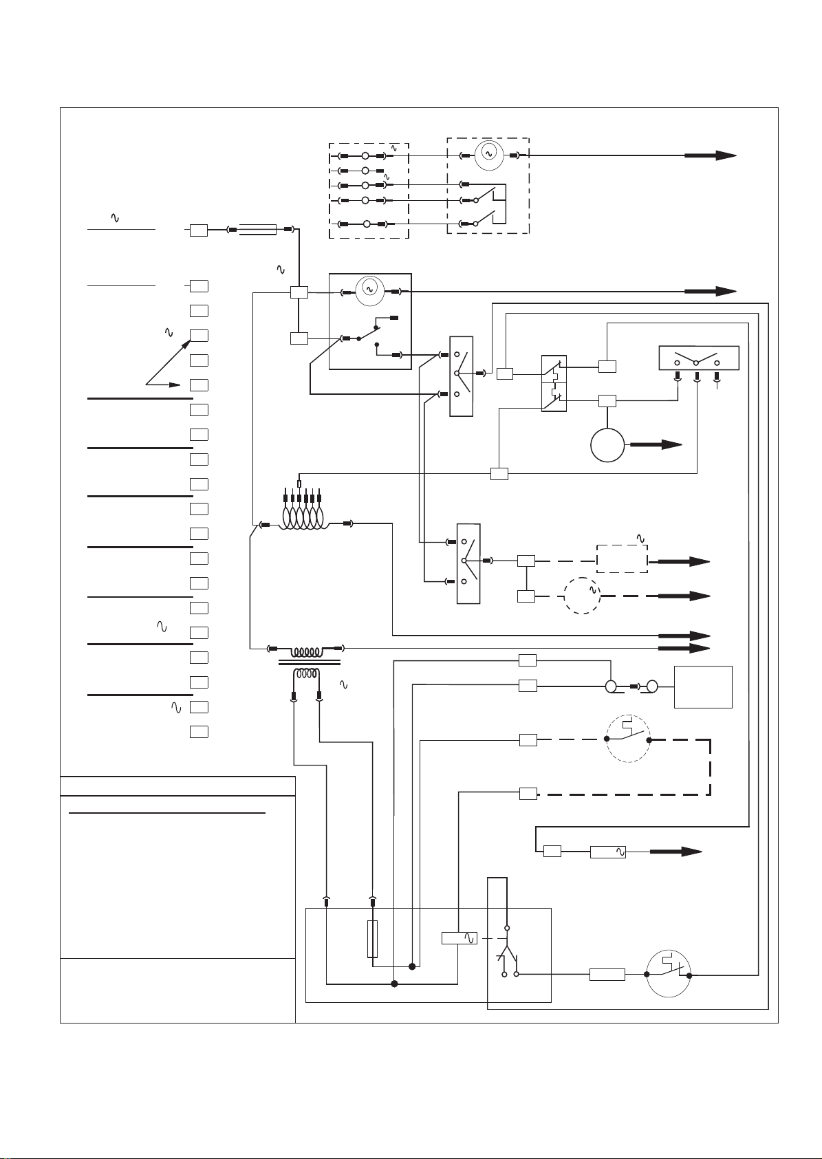
Fig. 6, FUNCTIONAL DIAGRAM
18
8
Comm.
24V Thermostat
(Not Fitted)
bk
FELV * Connection
br
br
15
230V
Multi-functional Control
w
br
Butt
Connector
b
Spill
Switch
(TTB)
br
r
Page 19
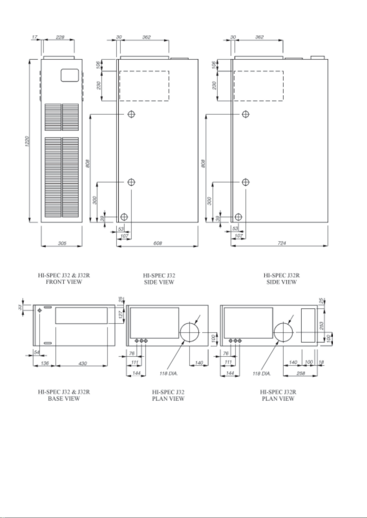
Fig. 7, PRINCIPA L DIMENSIONS (mm)
19
Page 20

10. SHORT LIST OF SPARES
HI-SPEC J32P and HI-SPEC J32RP
KE Y G . C No MFR’S No DESCRIPTION QTY
1 245 501 1000-0500370 Fan Assembly 1
2 H26-712 1000-0709640 Multifunctional Control 1
Honeywell V8600C 1129
BOS 02397/2 Pilot Burner 1
1000-0701440 Pilot Injector (No 19) 1
1000-0704730 Pilot Feed Pipe 1
390 210 BOS 01970 Igniter Electrode 1
BOS 02394 Igniter Lead 1
381 626 1000-0704830 Thermocouple 1
4 378 466 BOS 02031 Time Control 1
5 1000-0708020 Burner Bar Assembly 1
6 1000-0708040 Main Injector ( Bray 1.78mm ) 1
7 395 945 1000-0700570 Piezo Unit (High Energy) 1
8 245 509 1000-0513820 Fuse T3.15A anti-surge 1
1 3 386 634 1000-0503730 Spillage Monitor Device (TTB) 1
14 J304-0511000 Electrical Panel 1
1 5 245 520 1000-0516125 Fan Delay/Limit Control 1
16 1000-0515190 Transformer Fan Speed 1
1 7 245 525 1000-0515730 Transformer 24 volt 1
1 8 245 413 1000-0511760 Relay Module 1
19 J304-0769000 TTB Assembly (water heater) 1
Johnson and Starley prides itself on its ability to supply spar e parts quickly and efficiently. If you have a problem in obtaining a
spare part, please contact Johnson and S tarley Spares Department at the address below .
JOHNSON & STARLEY L TD.
T elephone: (01604) 762881 Rhosili Road,
Brackmills,
Fax: (01604) 767408 Northampton NN4 7LZ
 Loading...