

Johnson & Starley HI-SPEC J25RS Series Installation, Commissioning & Servicing Instructions

These instructions are to be left with the User or adjacent to the Gas Meter
HI-SPEC J25RS SERIES WARM AIR HEATERS
SYSTEM E-T and BASIC Control
INSTALLATION, COMMISSIONING & SERVICING INSTRUCTIONS
G.C. No 42 451 08
This appliance has been tested and certified by B G Technology for use with natural gas G20.
Note: For Balanced flue installations see BF25 Kit Instructions.
For Transfer Box installations see TBS25 Kit Instructions.
For Right Angle Transfer Box installations see TBR25 Kit Instructions.
For SUGG F60 replacement installations see TB25/F60 Kit Instructions.
For JGD25 replacement installations see TB25/JGD25 Kit Instructions.
1. BRIEF DESCRIPTION
1
Publication No. ZZ 810/6
December 2005
2
5
3
12
1 Air Filter
7
11
4
6
10
8
9
2 Air circulating fan
3 Heat exchanger access cover
4 Data plate
5 Electrical Panel Assembly
6 Multifunctional control
7 Fan delay control/limit switch
8 Viewing port
9 Pilot Burner
1 0 Burner Assembly
11 Gas supply pipe
1 2 Piezo igniter unit
Fig. 1
1. 1 HI-SPEC J25RS is a fanned-circulation, downflow, ducted warm air heater for SE-duct and balanced flue applications,
which may be supplied with SYSTEM E-T or Basic control.
1. 2 The Air heater output is 6.44kW (23.21MJ/h, 22,000Btu/h) or 7.3kW (26.4MJ/h, 25,000Btu/h) .
“Summer air circulation” of unheated air is available by manual selection (see User’s Instructions). HIJAN 6 output is
3.81kW (13.7MJ/h, 13,000Btu/h), whilst SUPERJAN 6 output is 6.0kW (21.6MJ/h, 20,470Btu/h).
THIS APPLIANCE CONFORMS TO BS EN 55014
1

Installation shall be in accordance with the current editions of:-
409
1
0
0
0
SPIGOT POSITION
FROM FRONT
FRONT VIEW
SIDE VIEW
TOP VIEW
BASE VIEW
2
8
2
5
5
24
255
1
1
5
463
2
8
8
3
6
8
140
28
476
330
343
455153157777
255
1
0
125
1
2
5
38
Building Standards (Scotland) (Consolidation) Regulations
Building Regulations
Gas Safety (Installation and Use) Regulations (as amended)
BS7671 Institute of Electrical Engineers (I.E.E.) Wiring Regulations
BS6891 Installation of Low Pressure Gas Pipework of up to 28mm (R1) in domestic premises (2nd family gases).
BS5440 Pt.1 (Flues for Gas Appliances)
BS5440 Pt.2 (Air Supply for Gas Appliances)
BS5864 Installation of Gas Fired Ducted Air Heaters
Model and Local Authority Bye-laws
IMPORTANT: STATUTE LAW DEFINES THAT ALL GAS APPLIANCES MUST BE INSTALLED BY COMPETENT
PERSONS, (i.e. CORGI REGISTERED INSTALLERS) IN ACCORDANCE WITH THE GAS SAFETY (INSTALLATION
AND USE) REGULATIONS (CURRENT EDITION). FAILURE TO COMPLY WITH THESE REGULATIONS MAY
LEAD TO PROSECUTION.
2.
HEATER COMPARTMENT AND CLEARANCES (See BS5864)
2.1 IMPORTANT: If the heater is to be fitted to an existing base duct (warm air plenum), always ensure that installation is
carried out such that the rear right hand corner of the heater is aligned with the rear right hand corner of the base duct, so
that any overhang or blanking off will be at the front and/or left hand side. In any event, blanking plates must be
mechanically secured and all joints sealed.
2. 2 When the heater is fitted into a compartment a minimum clearance from the compartment side walls of 38mm (1.5 in)
and 25mm (1.0 in) from the front must be left. Consideration should also be given to the space required for the removal
and replacement of the filter tray and the entry of the gas and electrical supplies.
2. 3 For service access, a minimum of 300mm (12 ins) is required at the front of the heater. Space must also be allowed, in a
compartment installation, to permit the removal of the heater. The clearance between the appliance and the compartment
should be not less than 75mm (3 in). However, if clearances are less than 75mm, the internal surface of the compartment
must be lined with non-combustible material. The compartment must be of a fixed rigid structure.
2. 4 The base duct on which the air heater stands must be only placed on a non-combustible floor.
2.5 IMPORTANT: The red ‘SAFETY’ label supplied with the heater, MUST BE AFFIXED in a prominent position
on the inside of the compartment door.
3.
VENTILATION AND COMBUSTION AIR
3. 1 A room sealed appliance does not require a combustion air vent in the room or internal space in which it is installed. If
the appliance is installed in a compartment, he minimum total free area of the high and low level ventilation air vents
must be as specified in Table 1 (as per BS5440 Pt 2 Table 1).
Note: These free areas allow for the operation of the appliance in combination with a HI-SPEC ELJAN/SE water heater.
2
VENTILA TE D Low level grille 132 cm
FROM INSIDE
BUILDING High level grille 132cm
VENTILA TE D Low level grille 66cm
FROM OUTSIDE
BUILDING High level grille 66cm
(20in2)
2
(20in2)
2
(10in2)
2
(10in2)
Table 1: Minimum Effective Areas
3. 2 Both vents must communicate with the same room or internal space, or must both be on the same wall to outside air. The
vertical distance between the vents shall be as large as is practicable.
2

4.
DUCT SYSTEM
All ductwork MUST be mechanically secured and sealed with good quality ducting tape.
4.1 RETURN AIR
4. 1.1 Room-sealed appliances may be installed without return air ducting provided that the path between the return air
grille and the appliance return air inlet is protected in such a manner that the required airflow will be maintained at
all times. The return air grille should have a free area of not less than 0.06m
2
(93 in2).
4.2 WARM DELIVERED AIR
4. 2.1 The base duct, which equalises the air pressure to supply ducts, shall be constructed to support the weight of the
heater, which shall be secured to the plenum with screws on at least two sides, and sealed using self-adhesive
foam strip, ducting tape or sealing compound. All ducting and blanking plates shall be mechanically secured and
sealed.
5. INSTALLATION
5.1 SIDE RETURN AIR
If return air is to be introduced via the side of the appliance, it will be necessary to prepare it prior to installation. Return
air ducting may be connected to either side of the heater as follows:
5. 1.1 Remove the air filter, front cover and the air circulation fan.
5. 1.2 Cut a hole in the chosen side of the fan compartment. The knock outs will determine the size and position.
5. 1.3 Remove and the filter frame retaining screws and remove the filter frame.
5. 1.4 Position the filter frame centrally over the prepared hole so that the front of the frame is flush with the front of
the heater.
5. 1. 5 Using the frame as a template, mark and drill the 6 x 3.2mm dia. frame fixing holes.
5. 1.6 Secure the filter frame to the side of the heater using the screws previously removed.
5. 1.7 Refit the air circulation fan, front cover and air filter.
5. 1.8 Using suitable material, manufacture a plate to cover the original return air opening in the top of the air heater, and
secure with self tapping screws (not provided).
5.2 SE-DUCT PREPARATION
5. 2.1 Ensure that the existing air heater has first been removed.
IMPORTANT: Many SE-ducts are constructed from asbestos-based materials, and due to dimensional
variations between Johnson & Starley and other manufacturers appliances, a certain amount of rework
will be required on the SE-duct by REGISTERED CONTRACTORS.
5.2 .2 In some circumstances, the SE-duct may be completely exposed and special components needed to complete the
installation. Consult Johnson & Starley Service Department if this situation is encountered.
5.2.3 Referring to Fig. 2, NOTE THE DATUM POINTS INDICATED before proceeding.
5. 2.4 Thoroughly clean and replace the sealing material from the top of the existing base duct.
5. 2. 5 The holes in the SE-duct MUST correspond with the positions ‘A’ and ‘B’ as shown in Fig. 2. Measure the
thickness of the SE-duct wall and cut pieces of 125mm (5 in) inside diameter tube of a suitable non combustible
material to length, and cement in place such that the upper tubing projects 38mm (1.5 in) into the SE-duct, and
the lower tubing is flush with the inside face of the duct. These positions are critical.
5. 2.6 Seal the redundant hole/s in the SE-duct using a suitable cement or blanking material, to ensure a good flat surface
on both the inner and outer faces of the duct wall.
IMPORTANT: Any debris which falls into the SE-duct MUST BE REMOVED.
5.2 .7 Referring to Fig. 2, drill 2 x 9mm diameter holes and fix the eye-bolts using the masonry plugs provided in the
installation kit.
3

Eye bolt
positions
360mm
DA TUM
Base of heater
142mm
A
455mm
B
Flue outlet
465mm
115mm
Combustion
air inlet
13mm (ref)
38mm
Important
Spigot MUST
NOT extend
into SE-duct
FRONT
Floor
HI-SPEC J25RS fitted to SE-Duct - fitting dimensions
5.3 SE-DUCT APPLICATION USING SE25 FIXING KIT
5.3 .1 Fit the orifice cup provided into the top (outlet) spigot of the air heater, such that the pre-drilled holes on both
components line up, and the hole in the cup is at the TOP of the spigot aperture as shown in Fig. 3 and secure
using the self tapping screw provided.
Note: The orifice cup must NOT be used in balanced flue applications.
Plenum
Fig. 2
SIDE
Fig. 3
Fitting of orifice cup
4

5.4 METHOD OF FIXING
5. 4.1 Due to base plan variations between the replacement and the original heaters, at some stage it may be necessary to
blank off part or parts of the base duct aperture. This can be done at the discretion of the installer, but it is
important that a suitable non-combustible material is used and that the perimeter of the remaining aperture is
bounded by suitable sealing tape to ensure a good seal between the heater and the base duct. Blanking plates
MUST be mechanically secure to the base duct, and the use of TAPE ALONE IS NOT ACCEPTABLE.
5. 4.2 The air heater must be mechanically secured to the base duct on at least 2 sides.
5. 4. 3 Position the rope ring seals on the heater spigots as shown in Fig. 2, and place the heater onto the base duct to
engage the spigots into the SE-duct holes.
5. 4.4 Hook the tie rods to the eye-bolt wall fixings, and secure using the brackets provided, hooked into the slots in the
front edge of the side of the air heater.
5. 4.5 Fit the nuts and washers provided, then carefully tighten the tie rods so that the air heater is effectively sealed
against the SE-duct.
Note: If the air heater is installed in a compartment, the warning label must be applied in a prominent position.
5.5 ELECTRICAL
5.5.1 Mains.
o
a. The heater is supplied with mains cable (PVC sheathed, heat resisting to 85
2
Green/Yellow, 6A, 0.75mm
), connected to a terminal block and exiting through the heater at the top left
C), 3-core Brown-Blue-
hand front. The cable is suitable for a 230V 50Hz supply and shall be connected to the fixed wiring
using a double pole switched, fused spur, incorporating a protective earth link. The fuse fitted shall be
rated 5A to BS1362. Connections shall be in accordance with the current edition of I.E.E Regulations BS
7671.
b. SYSTEM E-T MODELS: An electronic controller (Thermista-stat) is supplied which acts as a room
thermostat.
c. BASIC CONTROL MODELS: A 24V room thermostat (not supplied), that complies with BS800,
BS3955 and BS4201 is essential to ensure close control of comfort conditions. An anticipator is located
within the thermostat and is graded in amps. The anticipator should be checked and adjusted to 0.2A.
d. To gain access to the control panel to make the Thermista-stat/Room Thermostat connections, remove the
air filter and the front cover from the air heater.
5.5.2 Thermista-stat/Room Thermostat and its location.
a. The Thermista-stat/Room Thermostat should be located where there is free air circulation approx. 1.5m
(5ft) from the floor.
b. Avoid the following locations:-
i. In a room where temperature is greatly affected by the sun or any other heat source, e.g. radiant
fire, wall light fittings or TV set.
ii. Near an outside door or windows, or on an outside wall.
iii. Where affected by warm air ducts, diffusers, waste pipes or the heater itself.
iv. Where subject to vibration.
c. Connect Thermista-stat/Room thermostat wires to control panel terminals ‘7’ and ‘8’ (see Fig. 6a/b
or 7a/b).
5.3 GAS (See BS5864 and BS6891)
5. 3.1 An independent gas supply pipe from the meter is to be preferred wherever possible. When this is not possible,
the pipe must be capable of taking the complete input of the heater and all other gas appliances being served by
this same pipe. This supply should be suitably sized to conform to British Standards requirements of no more than
1.0 mbar (0.4in wg) pressure drop (See table of discharge in BS6891).
5. 3.2 The 1/2in union gas cock (supplied) must be fitted to the gas inlet of the heater for easy isolation during
servicing. The gas pipe should be so fitted and installed as to be durable, substantial and gas tight. To assist in
determining where a gas connection may not be tight, a leak detection fluid should be applied around the
connection. Under no circumstances should a flame be used to locate a gas leak. Gas entry to the air heater is
through either side to a Rc1/2 (1/2in BSP. external [taper] thread).
5

6.
COMMISSIONING
6.1 PREPARA TION:
6.1.1 Ensure that:
a. Gas and Electrical supplies are OFF .
b. Filter, fan and fan compartments are free from obstructions.
c. All registers or grilles are open and conform to design specifications.
d. Return, relief and ventilation air installations are adequate.
6.2 SETTING OF FAN SPEED:
6.2.1 Remove the air filter and fan chamber door.
SYSTEM E-T MODELS: On the electronic control module, set:
6.2.2 Rate Switch to ‘MAX’,
6.2.3 Cleanflow switch to ‘1’ if a Cleanflow electronic air cleaner is fitted, otherwise set to ‘0’.
6.2.4 Refit the fan chamber door and air filter.
6.3 IGNITION OF PILOT AND MAIN BURNERS:
WARNING: If the pilot light is extinguished either intentionally or unintentionally, no attempt should be made to
relight the gas for a minimum of 3 minutes. Ensure that the Electrical supply, time control and Selector switches are set
to ‘OFF’.
6.3 .1 Set the Thermista-stat/room thermostat to lowest or OFF setting.
6. 3.2 On the Multifunctional control, remove the Outlet Pressure test point cover, and fit a pressure test gauge (refer
Fig. 4).
6. 3. 3 Turn the heater Gas supply ON, test for gas soundness and purge the whole gas pipe as described in BS6891.
6. 3. 4 Referring to Fig. 4, partially depress the OPERATING CONTROL and set the control
1
/4 turn anti-clockwise to
the ‘SPARK’ symbol. Press and hold the OPERATING CONTROL, and whilst observing the Pilot Burner,
repeatedly press the Piezo igniter button until the Pilot burner ignites.
6. 3.5 After 20 seconds release the Multifunctional control OPERATING CONTROL and let it spring out; ensure that
the Pilot burner remains alight. If the Pilot burner extinguishes, rotate the Multifunctional control OPERATING
CONTROL clockwise to the ‘l ’ position and ensure that the OPERATING CONTROL is fully reset. Wait three
minutes and repeat steps 6.3.4 and 6.3.5, holding the OPERATING CONTROL depressed for a longer period, until
the Pilot burner remains alight.
6. 3.6 Ensure that the pilot flame envelops thermocouple tip, if not, check that the pilot orifices is free from
obstruction. The pilot is factory set and is non-adjustable.
6. 3. 7 With the Pilot burner lit, depress the OPERATING CONTROL and turn it to the position indicated by the flame
symbol.
6. 3.8 Set the air heater Electricity supply ON.
6. 3.9 Set the Time control to required Heating On periods.
6. 3.9 Set the Selector switch to ‘TIMED’.
6.3.10 Set the Thermista-stat or room thermostat to MAXIMUM.
6.3 . 11 Ensure that the main burner has now ignited.
6.3.12 Test for gas leakage at supply, Multifunctional control, Pilot and Main burners using proprietary detection fluid,
sealing any leaks found.
6.3.13 Allow heater to operate for a minimum of 15 minutes to ensure stability.
6

3
Sit
1
2
EV2
1. Operating control
2. Burner Pressure Adjuster
3. Outlet Pressure test point
Fig. 4
Multifunctional Control
6.4 MAIN BURNER PRESSURE TEST:
NOTE: AIR HEATER BURNERS ARE FACTORY SET TO PROVIDE A NOMINAL HIGH PRESSURE OUTPUT AS
DETAILED IN SUB PARA 1.2
6. 4.1 Referring to Table 2 and Fig. 4 below, ensure that the pressure test gauge indicates the correct burner pressure,
resetting if required as follows:
a. At the Multifunctional control:
i. Remove the Burner Pressure Adjuster cover.
ii. Set the Burner Pressure Adjuster to provide a pressure test gauge indication for the correct burner
pressure as detailed in Table 2.
iii. Refit the Burner Pressure Adjuster cover.
6. 4.2 Apply the pressure set arrow to indicate the appropriate burner pressure on the data badge.
6.5 EXTINGUISHING OF PILOT AND MAIN BURNERS:
6. 5.1 On the Multifunctional control, rotate the OPERATING CONTROL clockwise to the ‘l’ position and ensure that
the OPERATING CONTROL fully resets, and both the Pilot and Main Burners are extinguished.
6.5 .2 On the Multifunctional control, remove the pressure test gauge and refit the Outlet Pressure test point cover.
6.6 TEMPERATURE RISE CHECKS:
6. 6.1 Ignite Pilot and Main burners and allow 15 minutes for stability before continuing.
o
6. 6.2 Check temperature rise across heater is between 45
C - 55oC, setting fan speed as follows:
i. SYSTEM E-T heaters: System E-T provides a fan speed corresponding to the above temperature rise, if
the appliance is to be set to operate at the minimum rate and the ducting has been sized accordingly, set
the ‘RATE SWITCH’ to ‘MIN’, thus reducing the fan speed.
7

ii BASIC Control heaters, the fan speed is adjusted by selecting the fan speed at control panel
(decrease voltage selection to decrease fan speed).
6.7 AUT OMATIC CONTROLS CHECK
6. 7.1 Ignite the Pilot and Main burners and allow to operate for 15 minutes to ensure stability.
6. 7. 2 Set the TIME CONTROL (if fitted) to ‘ON’.
6. 7.3 Turn the Thermista-stat or room thermostat slowly clockwise until the Main burner ignites.
6. 7.4 Ensure that the fan starts to operate after a short period (approx. 1-2 minutes).
SYSTEM E-T models:
6. 7.5 Ensure that the fan speed increases to full speed.
6. 7.6 When the temperature reaches the control setting, check that the main burner cycles ON and OFF, at
approximately 75 to 120 seconds.
BASIC CONTROL models:
6. 7.7 When the temperature reaches the control setting, ensure that the Main burner extinguishes followed by the fan
switching off after a short period.
6. 7.8 When the temperature falls below the control setting, ensure that the Main Burner re-ignites followed by fan
operation.
6.8 SAFETY CHECKS:
6. 8.1 On Multifunctional control, rotate OPERATING CONTROL clockwise to ‘l’ position and ensure that the
OPERATING CONTROL fully resets, and both Pilot and Main Burners are extinguished.
6. 8.2 Switch OFF the electrical supply to the air heater.
6. 8.3 Release the securing screw and hinge down the fan chamber door.
6.8 .4 Disconnect the air circulation fan as follows:
a. System E-T models: disconnect the 2 x red conductors at the terminal block terminals ‘30’ and ‘31’
b. Basic control models: disconnect the 2 x black conductors at the terminal block terminals ‘16’
and ‘18’
6. 8.5 Switch ON the electrical supply to the air heater.
6. 8. 6 Ignite the air heater pilot and main burners, and check that the Limit switch operates between 120 and
180 seconds (indicated by the main burner extinguishing).
6. 8.7 Switch OFF the electrical supply to the air heater.
6. 8.8 Reconnect the air circulation fan at the terminal block.
6. 8. 9 Hinge up the fan chamber door, taking care to avoid causing damage to wiring, and secure using the 3 x screws
previously removed.
6.8.10 Switch ON the electrical supply to the air heater.
6.8 .11 Ensure that the Limit switch resets, indicated by the main burner igniting, within approximately 60
seconds.
6.8.12 Check for gas soundness within the appliance.
6.8.13 Turn OFF the gas supply at the service cock and ensure that the Multifunctional control fail-safe operates within
60 seconds (indicated by loud click from Multifunctional control).
6.9 SYSTEM BALANCING:
6. 9 .1 Set the ‘SUMMER AIR’ switch to ‘I’.
6. 9.2 Balance the system to provide required volume proportions at warm air outlets.
NOTE: If the system includes ceiling diffusers, air velocities through these should be NOT LESS THAN 1.5m/s (300ft/
min), except for very small rooms (ie. bathrooms etc.). Outlet faces may require partial blanking in order to achieve this.
6. 9 . 3 Set the ‘SUMMER AIR’ switch to ‘O’.
6. 9. 4 Turn the gas supply ON at the service cock.
6. 9.5 Ignite the Pilot and Main burners as detailed in sub-paras 6.3.4 to 6.3.7.
9.6 .6 Set the appliance to operate according to the user’s requirements.
8

LOW RAT E HIGH RATE
kW MJ/h Btu/h kW MJ/h Btu/h
INPUT 9.01 32.45 30,750 10.22 36.8 34,880
OUTPUT 6.44 23.21 22,000 7.33 26.38 25,000
Gas rate cv 0.80m3/h (28.3ft3/h) 0.9m3/h (31.9ft3/h)
1037Btu/ft
3
Burner setting 11.5mbar (4.6 in wg) 15.2mbar (6.1 in wg)
pressure (hot)
Main Injector BRAY CAT 960/480. 1.88 mm dia.
Table 2
Main Burner Pressure Settings
mbar in.wg.
0.375 0.15
0.25 0.10
0.125 0.05
1 00 150 200 2 50 300 ft3/min
3
0.05 0.07 0.09 0.12 0.14 m
/sec
AIR VOLUME
Table 3
Fan Performance Curve
INSTRUCTIONS FOR USERS
7.
7. 1 If the building is unoccupied, ensure that the Instructions for User are left taped to the air heater for the User, and
Installation Instructions are left at or near the air heater for use on future service calls.
7. 2 If the building is occupied, hand the User Instructions over and ensure the User understands:
7. 2. 1 How to ignite the pilot and burner.
7. 2.2 How to operate the Thermista-stat/room thermostat, time and heater ON/OFF switch and summer air circulation
switch, and that the time control must be reset following a power failure.
7. 2.3 How to extinguish the pilot and main burner at the Multifunctional control, and switch off electrical supply to the
heater.
7. 2. 4 How to remove, clean and refit the air filter and at what intervals (i.e. fortnightly, or for new houses, weekly).
7. 2.5 How to control the heating system by opening and closing warm air outlets.
7. 2.6 How to obtain summer air circulation.
7. 2.7 That the air grilles on the heater or heater compartment; grilles and ventilators in the walls, windows or doors of
the building must not be obstructed.
7. 2.8 That the heater must be serviced at least once a year by a competent person to ensure efficient and safe operation.
7. 2.9 That the red instructions for safe use have been pointed out and understood.
7.2.10 That expert help must be obtained if persistent failure of the pilot burner occurs.
9

8.
IMPORTANT: Ensure gas and electricity supplies are isolated before commencing any maintenance or
replacement of components. After completion of any maintenance, always test for gas soundness and carry
out a complete functional test of the appliance in accordance with Commissioning Instructions at Sect 6.1
to 6.8 inclusive. Replace any sealing gasket or insulation that is damaged before re-commissioning, taking
care to not disperse fibrous materials.
8.1 ROUTINE MAINTENANCE:
8. 1.1 Operate the appliance and check for the correct function of the burner and controls.
8.1 .2 Turn OFF the gas and electrical supplies to the appliance.
8.1 .3 Remove the air heater front panel.
8.1 .4 Remove and check the return air filter/cleaner for cleanliness, remove and clean the Air Circulation fan as
detailed in para 8.8.
8.1 .5 Remove the Burner and Controls Assembly as detailed in para 8.2. Inspect and clean the main burner and injector
as necessary. Examine the main burner for cracks, including hairline cracks, exchanging the burner as necessary.
8.1 .6 Inspect and clear the pilot burner orifice.
8. 1. 7 Clean the heat exchanger flueways by thoroughly brushing from above and below.
8. 1. 8 By viewing through the Fan Aperture, and using a torch or similar, examine the heat exchanger externally for signs
of cracks or holes, particularly around welded joints.
8. 1.9 Using a torch or similar, introduce a light source into the heat exchanger burner aperture and upper access port,
and again examine the heat exchanger for signs of cracks or holes, particularly around welded joints, whilst again
viewing through the Fan Aperture.
8.1.10 Refit the Air Circulation fan, Burner and Controls Assembly, and air filter/air cleaner.
8.1 .11 Light the appliance and note the main burner flame profile. If the flame profile is affected when the Air
Circulation fan switches on, check for any air leaks between the air heater and the base plenum, paying particular
attention to heaters with rear draught diverters. Rectify any air leaks before continuing with this procedure.
8.1.12 Allow the air heater to operate for approximately 15 minutes to ensure stability, and with the main burner lit,
ensure that the operation of Air Circulation fan does not affect the main burner flame profile.
8.1.13 If no defects are found, fully commission the air heater in accordance with the Installation, Commissioning and
Maintenance instructions applicable to the appliance.
8.2 BURNER AND CONTROL ASSEMBLY REMOVAL:
8. 2.1 Ensure that the Gas and Electrical supplies are switched OFF
8. 2.2 Remove the appliance door.
8. 2.3 Disconnect igniter at the piezo unit.
8.2. 4 Disconnect Multifunctional control electrical connections.
8. 2.5 Disconnect the gas supply by breaking the union at the input of the Multifunctional control.
8. 2.6 Remove the 9 Burner assembly securing screws and withdraw the Burner and Control Assembly.
8.2 .7 Refitment or replacement is in reverse order.
8.3 MAIN BURNER REMOVAL:
8. 3.1 Remove the Burner and Controls assembly as detailed in 8.2.
8.3 .2 Disconnect the pilot gas feed pipe from the Multifunctional control and the Pilot Assembly.
8.3 .3 Disconnect the Thermocouple from the Multifunctional control.
8. 3.4 Release the 4 x securing screws and withdraw the Pilot Assembly.
8. 3.5 Release the 2 x hexagonal headed screws situated above the main injectors, and remove the injector shrouds.
8.3 .6 Remove the 2 x main injector holders complete with injectors.
8. 3. 7 Release the 2 screws securing the Main Burner to the burner plate and withdraw the Main Burner.
8.3 .8 Refitment or replacement is in reverse order.
8.4 MAIN INJECTOR REMOVAL:
8. 4.1 Remove the Burner and Controls assembly as detailed in 8.2.
8. 4.2 Release the 2 x hexagonal headed screws situated above the main injectors, and remove the injector shrouds.
8.4 .3 Remove the 2 x main injector holders complete with injectors.
8.4 .4 Unscrew the main injectors from the holders.
8.4 .5 Refittment or replacement is in reverse order.
MAINTENANCE
10

8.5 PILOT BURNER ASSEMBLY REMOVAL:
8. 5.1 Remove Burner and Controls assembly as detailed in 8.2.
8.5 .2 Disconnect the pilot gas feed pipe from the Multifunctional control and Pilot Assembly.
8.5 .3 Disconnect the thermocouple from the Multifunctional control, taking care to avoid damage to the capillary.
8. 5.4 Release the 4 x screws securing the Pilot Assembly to the Burner and Controls assembly, and withdraw the Pilot
Assembly.
8.5 .5 Withdraw the Pilot injector from the Pilot Assembly.
8. 5.6 Release the Thermocouple lock nut from the Pilot Assembly and withdraw the Thermocouple, taking care to avoid
damage to the capillary.
8. 5.7 Release the Igniter electrode lock nut from the Pilot Assembly and withdraw the electrode.
8. 5.8 Refitting or replacement is in reverse order, ensuring that the Pilot Assembly gaskets are not damaged and that the
Pilot Assembly firmly seals with the Burner and Controls assembly. DO NOT over tighten the thermocouple
connection at the Multifunctional control, (finger tight plus 1 flat).
8.6 MULTIFUNCTIONAL CONTROL REMOVAL:
8. 6.1 Remove the Burner and Controls Assembly as detailed in 8.2
8. 6.2 Disconnect the Thermocouple at the Multifunctional control, avoiding damage to the capillary.
8.6 .3 Disconnect the Pilot gas feed pipe from the Multifunctional control.
8.6 .4 Disconnect the Multifunctional control input and output supply feeds.
8.6 .5 Refitting or replacement is in reverse order.
NOTE: When refitting or replacing the Multifunctional control, the ‘O’ ring seal is to be replaced.
8.7 PIEZO UNIT REMOVAL:
8.7 .1 Disconnect the 2 conductors from Piezo unit.
8. 7.2 Release the retaining nut and remove the Piezo unit from its mounting bracket.
8.7 .3 Refitting or replacement is in reverse order.
8.8 AIR CIRCULATING FAN, REMOVAL AND CLEANING:
8.8 .1 Ensure that the electrical supply is isolated.
8. 8.2 Remove the appliance front door, release the securing screw and hinge down the electrical panel.
8. 8.3 Remove the 3 x insulator covers and disconnect the fan flying leads, noting their position for subsequent
reconnection.
8. 8.4 Withdraw the fan flying lead cable tie from the fan chamber floor.
8. 8. 5 Release the Fan Assembly securing screw and withdraw the Fan Assembly from the Heater cabinet, avoiding
damage to the fan blades.
8. 8. 6 Remove all dust from both the impeller and motor, taking care to not disturb the balance of the fan.
8.8 .7 Refitting or replacement is in reverse order.
8.9 ELECTRICAL ASSEMBLY REMOVAL:
8.9 .1 Ensure that the electrical supply is isolated.
8. 9.2 Remove the appliance front door, release the securing screw and hinge down the electrical panel.
SYSTEM E-T models:
8.9 .3 Disconnect the following
a. Air circulation fan flying leads from the capacitor,
b. 230V mains ‘L’, ‘N’ and ‘E’ from connection block terminals ‘1’ and ‘2’, and Earth stud respectively,
c. Thermista-stat connections from connection block terminals ‘7’ and ‘8’,
d. Limit switch from connection block terminals ‘13’ and ‘14’,
e. Fan Delay Control from connection block terminals ‘18’ and ‘17’,
f. Multifunctional Control from connection block terminals ‘16 (N) and ‘15’ (L), and Earth stud.
g. Water heater from connection block terminals ‘10’ (L) and ‘9’ (N),
h. Water Pump from connection block terminals ‘12’ (L) and ‘11’ (N),
i. Cleanflow from connection block terminals ‘19’ (24V) and ‘20’ (0V),
j
. Earth lead from the fan chamber floor,
11

BASIC Control models:
8.9 .4 Disconnect the following:
a. Air circulation fan flying leads from the Fan assembly,
b. 230V mains ‘L’, ‘N’ and ‘E’ from connection block terminals ‘1’ and ‘2’, and Earth stud respectively,
c. Room thermostat connections from connection block terminals ‘7’ and ‘8’,
d. Limit switch from connection block terminals ‘13’ and ‘14’,
e. Fan Delay Control from connection block terminals ‘18’ and ‘17’,
f. Multifunctional Control from connection block terminals ‘16 (N) ,‘15’ (L) and Earth stud.
g. Water heater from connection block terminals ‘10’ (L) and ‘9’ (N),
h. Water Pump from connection block terminals ‘12’ (L) and ‘11’ (N),
i. Cleanflow from connection block terminals ‘19’ (24V) and ‘20’ (0V),
j. Earth lead from the fan chamber floor,
Both model types:
8. 9.5 Release the hinge screw and withdraw the Electrical assembly, releasing wiring from cable clamps and grommets
as required.
8.9 .6 Refitting or replacement is in reverse order.
8.10 ELECTRONIC MODULE REMOVAL (SYSTEM E-T models only)
8.10.1 Ensure that the electrical is isolated.
8.10.2 Remove the appliance front door, release the securing screw and hinge down the electrical panel.
8.10.3 Disconnect terminals ‘21’ to ‘33’ from the Electronic module.
8.10.4 Release the 2 x screws and nuts securing Electronic module to Electrical assembly and remove module.
8.10.5 Refitting or replacement is in reverse order.
8.11 TRANSFORMER REMOVAL (BASIC Control models only):
8.11 .1 Ensure that the electrical is isolated.
8.1 1.2 Remove the appliance front door, release the securing screw and hinge down the electrical panel.
8.11 .3 Disconnect the conductors from the large Transformer, noting their position for subsequent reconnection.
8.1 1.4 Release 2 x screws, nuts and star washers securing Transformer to the Electrical assembly, and remove the
Transformer.
8.11 .5 Refitting or replacement is in reverse order.
8.12 TIME CONTROL and SWITCH REMOVAL:
8.12.1 Ensure that the electrical is isolated.
8.12.2 Remove the appliance front door, release the securing screw and hinge down the fan chamber door.
Time Control removal:
8.12.3
8.12.4 Release the 3 x fixing screws, and withdraw the Time control.
8.12.5 Refitting or replacement is in reverse order.
8.12.6 Set Time Control to required ON and OFF times.
8.12.7 Set Time Control to correct time.
Switch removal:
8.12.8 Disconnect the conductors from the switch terminals.
8.12.9 Depress the retaining clips and press the switch out of the fascia panel.
8.12.10 Refitting or replacement is in reverse order.
WARNING: The fascia panel is held in place by push fit retainers which must be removed with caution to avoid
causing damage to the support pins. Removal of the fascia is not advised unless it is intended to be replaced.
8.13 FAN DELAY CONTROL/LIMIT SWITCH REMOVAL:
8.13.1 Ensure that the electrical supply is isolated.
8.13.2 Remove appliance front door, release the securing screw and hinge down the fan chamber door.
8.13.3 Disconnect the following at the Electrical panel:
8.13.4 Release the 2 x 4mm screws securing the Limit switch mounting plate, and withdraw the control from the
8.13.5 Refitting or replacement is in reverse order.
Disconnect conductors ‘C1’, ‘C2’, ‘C3’ and ‘C5’ from the Time control.
a. Limit switch from connection block terminals ‘13’ and ‘14’,
b. Fan Delay Control from connection block terminals ‘18’ and ‘17’,
c. Earth connection from common earth stud.
appliance by drawing the conductors through the grommet in the fan chamber floor.
12

8.14 HEAT EXCHANGER ACCESS:
8.14.1 Ensure that the electrical supply is isolated.
8.14.2 Remove the appliance front door.
8.13.3 Remove the Fan Delay Control/Limit switch wiring loom clip from the return edge of the fan chamber floor.
8.13.4 Release the 6 screws securing the access plate to the bulkhead, and withdraw the access plate and gasket.
8.13.5 Release the 8 screws securing the top access cover plate, and withdraw the cover plate and gasket.
8.13.6 Reassembly is in reverse order.
NOTE: When reassembling, ensure that the gaskets are soundly sealed, and fully re-commission the heater.
9.
9.1 IMPORTANT : If an electrical defect occurs after installation of the appliance; preliminary earth continuity,
polarity, and resistance to earth checks should be carried out with a multimeter. On completion of any
maintenance/fault-finding task that has required the breaking and remaking of electrical connections, then
checks of continuity, polarity, and resistance to earth must be repeated.
9.2 WARNINGS:
9. 2. 1 When purging or checking gas supplies, ensure that the ventilation to the room or cupboard is adequate, and that
all naked lights are extinguished.
9.2.2 SYSTEM E-T models:
a. When carrying out any electrical testing, a test meter MUST be used, since low resistance test devices can
cause damage to the Electronics module.
b. Before commencing defect diagnosis, ensure that the Thermista-stat is set to maximum, the mains supply
is ‘ON’ and the time control (if fitted) is at an ‘ON’ position.
c. Care is to be taken during the replacement and handling of electronic assemblies (ie electronic panel,
airflow sensor or Thermista-stat), it is not practical to rectify defects on these assemblies, except at the
manufacturer, and any attempt to do so may render the guarantee or factory replacement arrangement
invalid.
SYMPTOM POSSIBLE CAUSE REMEDY
a. Pilot will not light. i. No gas supply to heater. Check for gas at inlet pressure test
DEFECT DIAGNOSIS
point on multifunctional control.
ii. Gas supply pipe not purged. Purge gas supply pipe in accordance
with BS 6891.
iii Pilot orifice restricted. Clear pilot orifice or replace pilot injector.
iv Piezo system faulty. Check igniter, lead, and electrode.
v. Excessive gas supply pressure. Check that mains gas pressure is 20mbar,
and reduce if necessary.
b. Pilot lights but goes i. Connection between thermo- Check connection is secure.
out on releasing START couple and Multifunctional
button during initial control not secure.
light-up, or after
normal operation. ii . Faulty Multifunctional Replace Multifunctional control.
control.
iii. Faulty thermocouple. Replace pilot assembly.
iv. Pilot orifice restricted. Clear pilot orifice or replace pilot injector.
v. Air inlet/flue outlet fitted Check that inlet/outlet arrangements conform
incorrectly. to Fig. 3, and that seals are air tight.
c. Main burner lights but i. Loose electrical connection Check connections.
fan fails to run after on Fan Delay Control.
approximately 3 mins.
ii. Faulty Fan Assembly. Replace, taking care to not damage impeller.
iii. Faulty Fan Delay Control. Replace.
iv. Burner pressure setting incorrect. Adjust.
13

d. Main burner opera- i. Gas rate or burner pressure Check gas rate and burner pressure
ting intermittently setting high. setting.
with fan running.
ii. Temperature rise excessive. Adjust fan speed or gas rate accordingly.
iii. Air filter or return air path Check filter is clean and air path is clear.
restricted.
iv. Excessive number of outlets Open additional outlets.
closed.
e. Main burner opera- i. Gas rate or burner pressure Check gas rate and burner pressure
ting with intermittent setting too low. setting.
fan operation.
ii. Fan delay control faulty Replace.
f. Fan runs for excessive i. Fan delay control faulty. Replace.
period or operates
intermittently after
main burner shuts down.
g. Noisy operation. i. Gas pressure too high. Check burner pressure setting.
ii. Noisy fan motor. Replace fan assembly.
iii. Fan speed setting too high. Adjust fan speed.
SYSTEM E-T models:
h. Incorrect operation Fault related to SYSTEM E-T Consult diagnostic chart and follow
of fan or main burner. Control system (refer to pages 15 - 18) recommended procedure.
Basic control models:
j. Pilot alight but main i. Mains electrical supply not Check mains supply.
burner not igniting. connected to heater.
ii. Controls not demanding heat Check that time control (if fitted) and
room thermostat are operating correctly.
iii. T3.15A fuse failed. Replace. If failure occurs again, check
wiring for short circuits.
iv. Loose connection to room thermo- Check connections.
stat, limit switch, multifunctional
control lead, time control, relay
module or 24V transformer.
v. 230V/24V transformer failure. Check 24V side with test meter, if voltage
missing, replace transformer.
vi. Faulty relay module Check 230V at white wire from switch S5
vii.Multifunctional control faulty. Replace Multifunctional control.
viii.Limit control faulty. Short circuit control and replace if necessary.
ix. Room thermostat or external Fit temporary loop in heater thermostat
wiring faulty. socket. If heater ignites, external circuit
or room thermostat is faulty.
9. 3 The SYSTEM E-T module is fitted with a diagnostic light emitting diode (LED) which is visible through a hole in the
module cover, as shown in Fig. 5 below. If the LED is flashing, this means that :
9. 3.1 The fan is not connected, or
9. 3.2 The capacitor is not connected, or
9. 3. 3 There is a short circuit in the fan supply.
14

SYSTEM E-T DEFECT DIAGNOSIS FLOW CHART
MAIN BURNER NOT OPERATING
SWITCH ON
230 V
REPLACE
MULTIFUNCTIONAL
CONTROL
CHECK WIRING TO
MULTIFUNCTIONAL
CONTROL
LINK TERMINALS ‘13’
& ‘14’, IF BURNER
LIGHTS REPLACE
FAN/LIMIT CONTROL
CHECK WIRING
CONNECTIONS
IS
PILOT
LIT ?
N
Y
N
IS 230V
SUPPL Y
ON ?
LIGHT
PILOT
Y
IS TIME
CONTROL &
THERMISTA-STAT
CORRECTLY
SET ?
N
SET CONTROLS
Y
DISCONNECT THERMISTA-ST A T
AT TERMINALS ‘7’ & ‘8’, LINK
TERMINALS ‘7’ & ‘TEST’
RECONNECT THERMISTA-ST A T
DOES
FAN
RUN ?
Y
DISCONNECT ON CONNECTION
N
CHECK FOR 230V AT
Y
MULTIFUNCTIONAL
CONTROL
N
Y
CHECK FOR 230V AT
TERMINAL 15
N
Y
CHECK FOR 230V AT
TERMINAL 13
N
Y
CHECK FOR 230V AT
TERMINAL 29
IS
GAS
TURN GAS
N
ON
ON ?
Y
CORRECTL Y
AT TERMINALS ‘7’ & ‘8’,
A T THERMISTA-ST A T
DOES
FAN
RUN ?
N
EXTERNAL WIRING TO
THERMISTA-STAT
FAULTY
Y
REPLACE
THERMISTA-STAT
CHECK WIRING
CONNECTIONS
REPLACE AIR HEATER
SWITCH
CHECK FOR 230V AT
TERMINAL 27
Y
CHECK FOR 230V AT
CENTRE TERMINAL OF
SWITCH ‘S5’
Y
CHECK FOR 230V AT
TIME CONTROL
TERMINAL ‘C5’
REPLACE TIME
CONTROL MECHANISM
N
Y
REPLACE
ELECTRONIC
MODULE
N
N
N
15

F AN OPERATES, BUT BURNER CYCLES BEFORE REQUIRED TEMPERATURE IS REACHED
DISCONNECT THERMISTA-ST A T
AT TERMINALS ‘7’ & ‘8’, LINK
TERMINALS ‘7’ & ‘TEST’
DO NOT LINK ‘7’ &’8’
DOES
REPLACE
THERMISTA-STAT
N
CHECK RETURN AIR PATH
THE BURNER
CONTINUE TO
CYCLE?
Y
FOR RESTRICTIONS
DOES
THE BURNER
CONTINUE TO
CYCLE?
Y
CHECK TEMPERATURE RISE.
O
IF LESS THAN 60
C, LINK
TERMINALS ‘13’ & ‘14’
DOES
THE BURNER
CONTINUE TO
N
REPLACE FAN DELAY/
LIMIT CONTROL
CYCLE?
Y
REPLACE
ELECTRONIC
MODULE
MAIN BURNER ON, BUT FAN NOT RUNNING
CHECK FOR
VOL TAGE A T
TERMINALS
30 & 31
N
DISCONNECT FAN LEADS
Y
FROM CAPACITOR, AND
CONNECT DIRECT TO FAN
REPLACE FAN
DELA Y/LIMIT
CONTROL
BRIDGE OUT
F AN DELA Y AT
TERMINALS 21 & 22
Y
DOES
FAN
START?
N
REPLACE
ELECTRONICS
MODULE
16
DOES
FAN
START?
N
REPLACE
FAN
Y
REPLACE
CAPACITO R

FAN RUNS BUT MAIN BURNER NOT OPERATING
IS
‘SUMMER
AIRFLOW’
SWITCH
SET TO
‘0’
Y
IS
THERMISTA
-STAT
CONNECTED
Y
IS
THERMISTA
-STAT SET TO
‘SUMMER
AIRFLOW
N
N
SET ‘SUMMER
AIRFLOW SWITCH TO
‘0’
CONNECT
THERMISTA-STAT
Y
SET THERMISTA-ST A T TO
REQUIRED
TEMPERATURE SETTING
DOES
FAN STILL
RUN ?
Y
DISCONNECT THERMISTA-ST A T
AT TERMINALS ‘7’ & ‘8’, LINK
TERMINALS ‘7’ & ‘TEST’
DO NOT LINK ‘7’ &’8’
DOES
FAN STILL
RUN WITH
BURNER
LIT?
N
CHECK THERMISTA-STAT WIRING.
IF OK, REPLACE THERMIST A-STAT.
N
IF NOT, RECONNECT TERMINALS
‘7’ & ‘8’, AND SET THERMISTA-STAT
FAULT
CLEARED
TO DEMAND HEA T
Y
REPLACE ELECTRONIC
MODULE. RECONNECT
THERMISTA-STAT
HAS
FAN STOPPED
AND BURNER
LIT?
Y
17
HAS
BURNER
LIT?
Y
F AN OPERATES AFTER BURNER HAS
RAISED THE INTERNAL
TEMPERA TURE T O CAUSE THE F AN
DELA Y CONTROL T O OPERATE

MAIN BURNER NOT CYCLING
(ROOM TEMPERATURE TOO HIGH)
DISCONNECT
THERMISTA-STAT
DOES
BURNER
GO OUT?
Y
REPLACE
THERMISTA-STAT
N
DISCONNECT
MULTIFUNCTIONAL
CONTROL AT
TERMINAL 15
DOES
BURNER
GO OUT?
Y
REPLACE
ELECTRONICS
MODULE
N
REPLACE
MULTIFUNCTIONAL
CONTROL
FAN CONTINUES TO RUN, OR CYCLES AFTER HEATING IS TURNED OFF
DISCONNECT
TERMINALS ‘17’ &’18’
DOES
FAN
RUN ?
Y
N
REPLACE FAN DELAY/
LIMIT CONTROL
REPLACE
ELECTRONIC
MODULE
Diagnostic LED
Fig. 5
SYSTEM E-T Electronic module
18

Fig. 6a, SYSTEM E-T FUNCTIONAL DIAGRAM
19
r

Fig. 6b, BASIC CONTROL FUNCTIONAL DIAGRAM
20

Fig. 7a, SYSTEM E-T CIRCUIT DIAGRAM
r
21
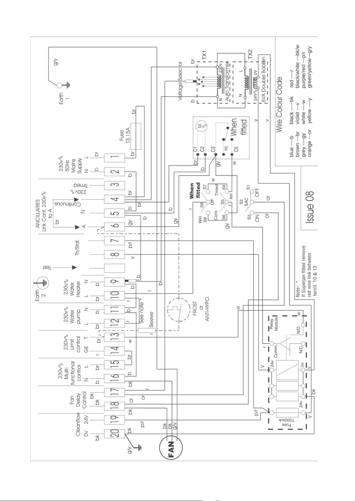
Fig. 7b, BASIC CONTROL CIRCUIT DIAGRAM
r
22

409
1
0
0
0
SPIGOT POSITION
FROM FRONT
FRONT VIEW
SIDE VIEW
TOP VIEW
BASE VIEW
2
8
2
5
5
24
255
1
1
5
463
2
8
8
3
6
8
140
28
476
330
343
455153157777
255
1
0
125
1
2
5
38
Fig. 8, PRINCIPA L DIMENSIONS (mm)
23

10. SHORT LIST OF SPARES
HI-SPEC J25RS
K E Y G .C No MFR’S No DESCRIPTION QT Y
1 232 961 BOS 02064 Fan Assembly 1
2 245 508 R253-0145000 Filter Assembly 1
3 378 466 BOS 02031 Time Control 1
4 381 627 1000-0701140 Multifunctional Control 1
5 232 948 BOS 02061 ‘O’ Ring Seal 2
6 245 545 1000-0705000 Pilot Burner Assembly 1
7 245 548 1000-1500850 Pilt Burner Gasket 1
8 390 210 BOS 00036 Thermocouple 1
9 245 509 1000-0513820 Fuse T3.15A anti-surge 1
10 245 504 R253-0700000 Burner and Controls Assembly 1
11 242 289 1000-0701350 Burner and Cross Lighter Assembly 1
12 399 849 BOS 02375 Main Injector 1
13 384 505 BOS 01441 Piezo Unit 1
14 393 623 BOS 01449 Igniter Electrode 1
System E-T Models Only
15 245 511 ET002 Electronic Panel Assembly and Daughter board 1
16 245 514 1000-0515620 Thermista-stat 1
17 245 515 1000-0515455 Fan Delay Control/Limit Switch 1
18 245 542 1000-0515970 Capacitor 15µf 1
Basic Models only
19 245 518 R253-0505000 Electrical Panel and Clock Assembly 1
20 245 517 1000-0515770 Electrical Chassis assembly 1
21 245 520 1000-0516125 Fan Dely Control/Limit Switch 1
22 245 522 1000-0515200 Fan Speed Transformer 1
23 245 525 1000-0515730 Transformer 24V 1
24 245 413 1000-0511760 Relay Module 1
Johnson and Starley prides itself on its ability to supply spare parts quickly and efficiently. If you have a problem in
obtaining a spare part, please contact Johnson and Starley Spares Department at the address below.
JOHNSON & STARLEY LTD.
Telephone: (01604) 762881 Rhosili Road,
Brackmills,
Fax: (01604) 767408 Northampton NN4 7LZ
24
 Loading...