

Page 1
These instructions are to be left with the User or adjacent to the Gas Meter
Johnson
& Starley
HI-SPEC J25 WARM AIR HEATERS
SYSTEM E-T and Basic Control
INSTALLATION, COMMISSIONING & SERVICING INSTRUCTIONS
G.C. No 42 451 04
Publication No. ZZ 753/12
January 2010
This appliance ha been tested and certified by G . L. Industrial Services UK Ltd. for use with natural gas G20.
Note: If a HIJAN 6 or SUPERJAN 6 circulator is fitted, the relevant Installation, Commissioning and Servicing instructions
provided with that appliance must also be observed.
1. BRIEF DESCRIPTION
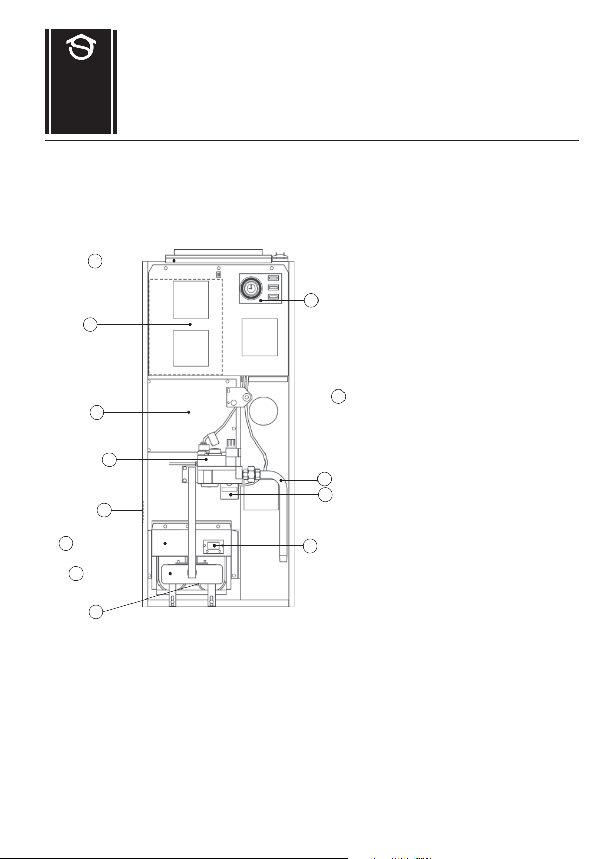
1
13
2
12
3
4
11
10
5
6
7
8
Fig. 1
9
1 Air filter
2 Air circulating fan
3 Heat exchanger access cover
4 Multifunctional control
5 Data Plate
6 Heat shield
7 Burner assembly
8 Pilot burner
9 Lighting port
10 Fan delay control/limit switch
11 Gas supply pipe
1 2 Piezo igniter unit
1 3 Time control
1.1 HI-SPEC J25 is an open-flued, fan assisted downflow, ducted warm air heater , which may be supplied with SYSTEM E-T or
1.2 The Air heater output can be adjusted between 5.6kW (20.0MJ/h, 19,000Btu/h) and 7.3kW (26.4MJ/h, 25,000Btu/h). “Summer
Basic control. A HIJAN 6 or SUPERJAN 6 circulator is available as an option. A pilot burner incorporating an Atmospheric
Sensing Device (ASD) is fitted which responds to the presence of flue gases and shuts down the appliance.
air circulation” of unheated air is available by manual selection (see User’s Instructions). HIJAN 6 output is 3.81kW (13.7MJ/
h, 13,000Btu/h), whilst SUPERJAN 6 output is 6.0kW (21.6MJ/h, 20,470Btu/h).
THIS APPLIANCE CONFORMS TO BS EN 45014
1
Page 2

Installation shall be in accordance with the current editions of:
Building Standards (Scotland) (Consolidation) Regulations
Building Regulations
Gas Safety (Installation and Use) Regulations (as amended)
BS7671 Institute of Electrical Engineers (I.E.E.) Wiring Regulations
BS6891 Installation of Low Pressure Gas Pipework of up to 28mm (R1) in domestic premises (2nd family gases).
BS5440 Pt.1 (Flues for Gas Appliances)
BS5440 Pt.2 (Air Supply for Gas Appliances)
BS5864 Installation of Gas Fired Ducted Air Heaters
British System Design Manual “Gas Fired Warm Air Heating”
Model and Local Authority Bye-laws
BS5546 Installation of Domestic Hot Water Supplies.
IMPORT ANT: ST ATUTE LA W DEFINES THAT ALL GAS APPLIANCES MUST BE INSTALLED BY COMPETENT PERSONS,
(i.e. GAS SAFE REGISTERED INSTALLERS) IN ACCORDANCE WITH THE GAS SAFETY
(INSTALLA TION AND USE) REGULA TIONS (CURRENT EDITION). FAILURE T O COMPLY WITH THESE
REGULATIONS MA Y LEAD TO PROSECUTION.
2. HEATER COMPARTMENT AND CLEARANCES (SEE BS5864)
2.1 IMPORTANT: If the heater is to be fitted to an existing base duct (warm air plenum), always ensure that installation is
carried out such that the rear left hand corner of the heater is aligned with the rear left hand corner of the base duct, so that
any overhang or blanking off will be at the front and/or right hand side. In any event, blanking plates must be mechanically
secured and all joints sealed.
2.2 When the heater is fitted into a compartment, a minimum clearance from the compartment walls of 15mm at the sides and rear,
and 25mm at the front must be left. Consideration should also be given to the space required for the removal and
replacement of the filter tray and the entry of the gas and electrical supplies.
2.3 For service access, a minimum of 450mm (18ins) is required at the front of the heater. Space must also be allowed, in a
compartment installation, to permit the removal of the heater. The clearance between the appliance and the compartment
should be not less than 75mm (3 in). However, if clearances are less than 75mm, the internal surface of the compartment
must be lined with non-combustible material. The compartment must be of a fixed rigid structure.
2.4 In airing cupboard installations, the part used as the air heater compartment must comply with the relevant section of
BS5864 and must be completely separated by either a non-combustible partition or a perforated metal partition with the
perforations not exceeding 13mm (1/2in). The secondary flue must be a tight fit where it passes through the partition and
must be suitably protected (see BS5440: Part 1).
2.5 In under-stairs installations, the compartment must comply with the relevant section of BS5864, provided that in addition, all
internal surfaces, including the base, are non-combustible or lined with non-combustible material. This requirement is
applicable only to dwellings of more than two storeys.
2.6 If the Air Heater is to be installed onto a combustible surface, a suitable base tray (BT25) is required. However, when a base
duct is used, this provides sufficient protection for combustible material and no further insulation is required.
3. VENTILA TION AND COMBUSTION AIR
3.1 The room or internal space in which the heater is installed requires a permanent air vent of minimum effective area 36cm
2
(5in2). The air vent should be either direct to outside air or to an adjacent room or internal space (other than a toilet or
bathroom) that itself has an equivalent air vent direct to outside.
3.2 Combustion air may be introduced, via a 100mm (4in) nominal bore pipe, connected to a return air duct or plenum from a
ventilated area and fitted with a lockable damper. The damper should be adjusted to control combustion airflow to 0.0083m
3
s (17.6cfm), (i.e. 1.06m/s [210ft/min] velocity in a 100mm [4in] bore pipe). If this arrangement is used, a non-closeable warm air
register MUST be provided in the same area as the front of the air heater or heater compartment if a return air grille is not
located in that area.
/
3.3 When installed in a compartment, two permanent ventilation openings into the compartment are required, one at high level
and one at low level, both communicating either directly with outside air or with a ventilated room or space. The minimum
effective areas specified in Table 1 are related to the rated heat input of the Air Heater, and assuming that a HIJAN 6
circulator is fitted. If a SUPERJAN 6 circulator is fitted, the minimum area is greater, and reference made to the relevant
installation instructions for the circulator.
3.4 If any room or area from which air is drawn for ventilation or combustion contains an extract fan, the permanent vents must
be sized to ensure that the operation of the appliance(s) at full rate is/are not adversely affected. A spillage test as specified
in sub-para 6.8 (Safety Checks) is carried out and any remedial work undertaken.
2 27
Page 3

Ven ti la t e d fro m i ns id e
building.
Low leve l g r ille 2 84c m
2
(44in2)
Hig h leve l g r ille 142 cm
2
(22in2)
Ven t i la t e d fro m
o utside bu ild in g .
Low leve l g r ille 142c m
2
(22in2)
Hig h leve l g r ille 7 1cm
2
(112)
T able 1: Minimum Efective A reas
4 DUCT SYSTEM
(See British Design Manual- Gas Fired W arm Air Heating)
4.1 RETURN AIR
4.1.1 It is NOT recommended that the return air duct be routed directly from the main living area, but from a convenient
central area serving the remainder of the dwelling.
4.1.2 All return air shall be POSITIVELY ducted from outside the compartment to the top of the unit via a return air duct.
Where required, return air can be ducted to the side of the heater by transferring the return air spigot. Refering to fig.
9 (page25), remove the 4 x knockouts and use the return air spigot as a template in order to mark out where to cut the
heater casing. Using a 2.9 mm bit, drill the fixing holes and secure using the previously removed screws. Fit the
supplied blanking plate to the top of the heater and secure using the screws supplied with the blanking plate. NB
remove swarfe from the air heater compartment prior to installation and commissioning!
4.1.3 The return air system should be constructed of fire-resistant material. The flue shall not be run through an area
serving as a return air path. It is extremely important that the correct size of return air grilles and ducting is used. For
heaters on maximum output the return air duct size should not be less than the equivalent of 200mm x 200mm ( 8" x
8"). If flexible duct is used the duct diameter should not be less than 250mm (10") dia. The return air grille should
have a free area of not less than 645cm
2
(100in2).
4.1.4 An adequate and unobstructed return air path is essential from areas not served by a directly ducted return and to
4.1.5 The return air duct should allow for ease of removal for access to the flue.
4.1.6 All duct work in the room or internal space in which the heater is installed shall be mechanically secured, and sealed
4.2 W ARM DELIVERED AIR
4.2.1 All duct work, including riser ducts, should be fully insulated with 50mm (2in) fibreglass or similar. If short extended
4.2.2 The duct system should be carefully designed (as given in the guidelines in the British System Design Manual) to
5. INSTALLATION REQUIREMENTS
Note: For circulator Installation Instructions, refer to the relevant instructions provided with the circulator.
5.1 FLUES (SEE BRITISH ST ANDARDS BS5440 PT.1 FLUES)
5.1.1 All joints shall be soundly sealed.
5.1.2 The flue should be kept as short and warm as possible.
5.1.3 Sufficient support brackets shall be installed to bear the weight of the total flue system.
5.1.4 The spigot connection of the heater draught diverter will accept internally the spigot end of a non-asbestos flue to
2
which warm air is delivered. All such rooms should be fitted with relief grilles which have a free area of 0.0088m
2
/250Btu/h) of heat supplied to the room. The only exceptions are kitchens, bathrooms and WC.’ s.
(1in
/kW
with ducting tape.
duct runs are taken below floor level these should be similarly insulated, and in addition wrapped with a sound
vapour proof barrier, and protected from crushing.
suit the needs of its specific heating requirements and building layout. The type of duct system, (i.e. radial/extended
plenum/stepped) should be installed using the least number of fittings to minimise airflow resistance. The base duct,
which equalises the air pressure to supply ducts, shall be constructed to support the weight of the heater, which
shall be secured to the plenum with screws on at least two sides, and sealed using self-adhesive foam strip, ducting
tape or sealing compound. All ducting and blanking plates shall be mechanically secured and sealed.
BS567 or twin wall metal flue to BS715 of nominal 100mm (4in) diameter.
3
Page 4

SIDE VIEW
BASE V IEW
FRONT VIEW
TOP VIEW
9
9
5
326088
300
51
2065010
254
376
120 dia.
90
440
695
3
0
0
3
8
4
1
3
2
5
6
2
2
1
0
253
21
393
115
3
9
3
5
1
2
593
60067
0
5.1.5 A split collar should be fitted to provide for flue maintenance or inspection.
5.1.6 The flue shall be in accordance with the Building Regulations and British Gas Materials and Installations specification 3rd edition) with regard to clearance and shielding from combustible materials.
5.1.7 All materials shall be in accordance with Building Regulations requirements.
5.1.8 The flue should run as vertically as possible. Horizontal runs should be avoided if at all possible and any directional
change should be as gentle as possible. If there is any doubt about the flue configuration, the equivalent flue height
should be determined (see 5.1.10).
5.1.9 I f th e appliance to be fitted is a replacement, the old appliance should be checked for signs of spillage prior to
commencement of the installation and appropriate action taken, (i.e. check flue system and renew as necessary).
5.1.10 It is recommended that at least 600mm of vertical flue should be provided from the top of the draught diverter (for
new installations this shall be incorporated into the flue design). However, when carrying out replacement
installations, an existing flue system may be encountered, where the vertical flue above the appliance to the first
bend is less than 600mm. In the first instance, the installer must judge whether this distance can be achieved
practicably by some means. Where this is not practicable, the existing flue system may be used, providing there is no
evidence of spillage from the old appliance (see 5.1.9 above). Every effort must be made, however, to ensure that the
existing flue complies in every other way to BS 5440 Part 1, including the visual inspection, flue flow and spillage test
described in 4.3.2 of the above standard. Flue configurations may be assessed in terms of equivalent vertical height details are given below. For air heaters, the minimum equivalent vertical height is 1 metre. The installer must make a
judgement based on his knowledge and experience and the examination and testing described above as to whether
an existing flue system can be used.
Note: Ventilation of the compartment, room or internal space in which the appliance is to be installed must be checked for
compliance with the requirements of BS 5440 Part 2, ( Ref. Section 3 of these instructions) and upgraded as
necessary.
5.1.11 Calculation method for flue sizing: (BS 5440: Part 1, Appendix A)
a. This appendix provides a procedure for estimating whether a given flue design is likely to ensure full
clearance of combustion products.
b. The procedure is based on calculating the ‘equivalent height’ of the flue under consideration, i.e. that height
of the straight vertical circular flue pipe of specific size which will produce the same flow rate as the flue
under consideration. The equivalent height is calculated from the formula:
(K
He = Ha x
(Ki + Ko)a - KeHa + Sum K
+ Ko )
i
e
where:
is the height of the equivalent flue;
H
e
is the vertical height of the actual or proposed flue;
H
a
Ki is the inlet resistance of the flue;
is the outlet resistance from the flue;
K
o
subscript e refers to the equivalent flue diameter;
subscript a refers to the actual or proposed flue diameter;
is the resistance per unit length of the equivalent flue;
K
e
Sum K is the resistance (other than the inlet and outlet resistance) of the actual or proposed flue.
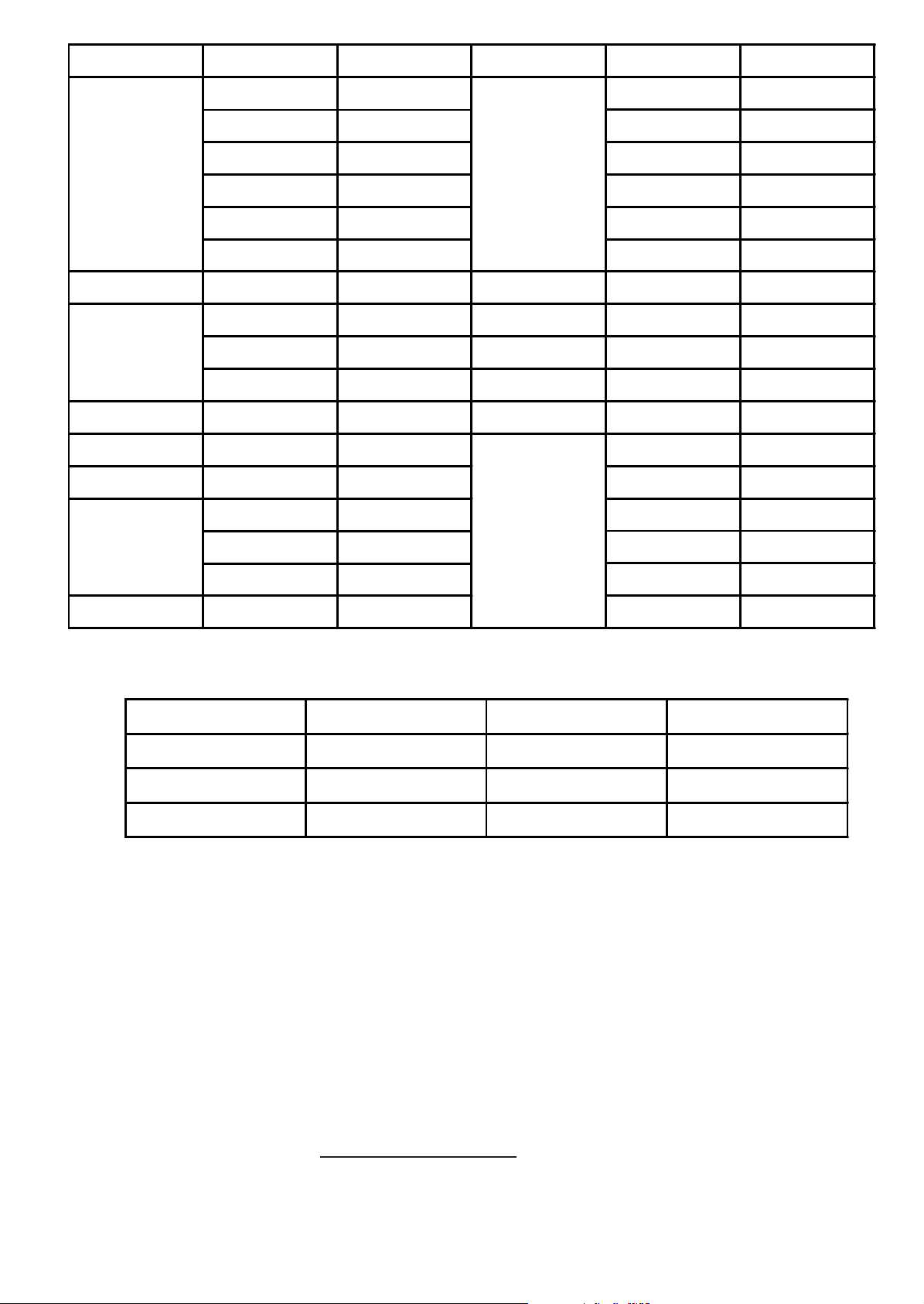
Note: K and Sum K are obtained from T able 2. K
and Ki are obtained from T able 3.
o
c. Table 2 gives resistance factors for common flue components for use in the formula. Table 3 contains the
appropriate inlet and outlet flue resistances. The flue is likely to be satisfactory if its equivalent height exceeds 1m.
d. W orked Calculation Example:
A warm air unit with a 100 mm diameter flue spigot, fitted with a pre-fabricated flue system leading to a ridge
tile in the loft (refer Fig. 2):
From table 3:
Inlet resistance of actual flue . . . . . . . . 2.5
K
ia
Outlet resistance of actual flue . . . . . . 2.5
K
oa
Inlet resistance of equivalent flue . . . . 2.5
K
ie
Outlet resistance of the actual flue . . . 2.5
K
oe
Page 5
Component Internal Size (mm) Re s istance Components Internal Size (mm) Re s is tance
Flue Blocks
197 x 67 0.85 per metre
45
o
bend
100mm pipe 0.61 per fitting
231 x 65 0.65 run 125mm pipe 0.25 per fitting
317 x 63 0.35 150mm pipe 0.12 per fitting
140 x 102 0.60 197 x 67 0.30 per fitting
200 x 75 0.60 231 x 65 0.22 per fitting
183 x 90 0.45 317 x 63 0.13 per fitting
Pipe
100 0.78 Raking Block Any 0.30 per block
125 0.25
150 0.12 Adaptor Block Any 0.50 per block
C himney 2 1 3 x 21 3 0.0 2
Terminal
100mm ridge 2.5
125mm ridge 1.0
90
o
Bend
100mm pipe 1.22 per fitting 150mm ridge 0.48
125mm pipe 0.50 per fitting 100mm GCI 0.6
150mm pipe 0.24 per fitting 125mm GCI 0.25
150mm GCI 0.12
Appliance Inlet Resistance ( Ki) Flue Out let res is t ance (Ko)
100mm Dia Spigot 2.5 100mm 2.5
125mm Dia Spigot 1.0 125mm 1.0
150mm Dia Spigot 0.48 150mm 0.48
T able 2
Resistance factors for use in calculating equivelent lengths
T able 3
Inlet and outlet resistance
From table 2:
Other resistances of actual flue:
Terminal . . . . . . . . . . . . . . . . . . . . . . . . . . . . . 2.5
Pipe bend ( 2 x 0.61) . . . . . . . . . . . . . . . . . . . . 1.22
Pipe (4 x 1m @ 0.78) . . . . . . . . . . . . . . . . . . . 3.12
(5 x 0.3m @ 0.78) . . . . . . . . . . . . . . . . . . 1.17
Sum K . . . . . . . . . . . . . . . . . . . . . . . . . . . . . . 8.01
Equivalent height :
From the formula
(2.5 + 2.5)
= 6.2 x
H
e
(2.5 + 2.5) - (0.78 x 6.2) + 8.01
= 3.793 This flue exceeds 1.0m equivalent height and is therefore satisfactory.
H
e
Page 6
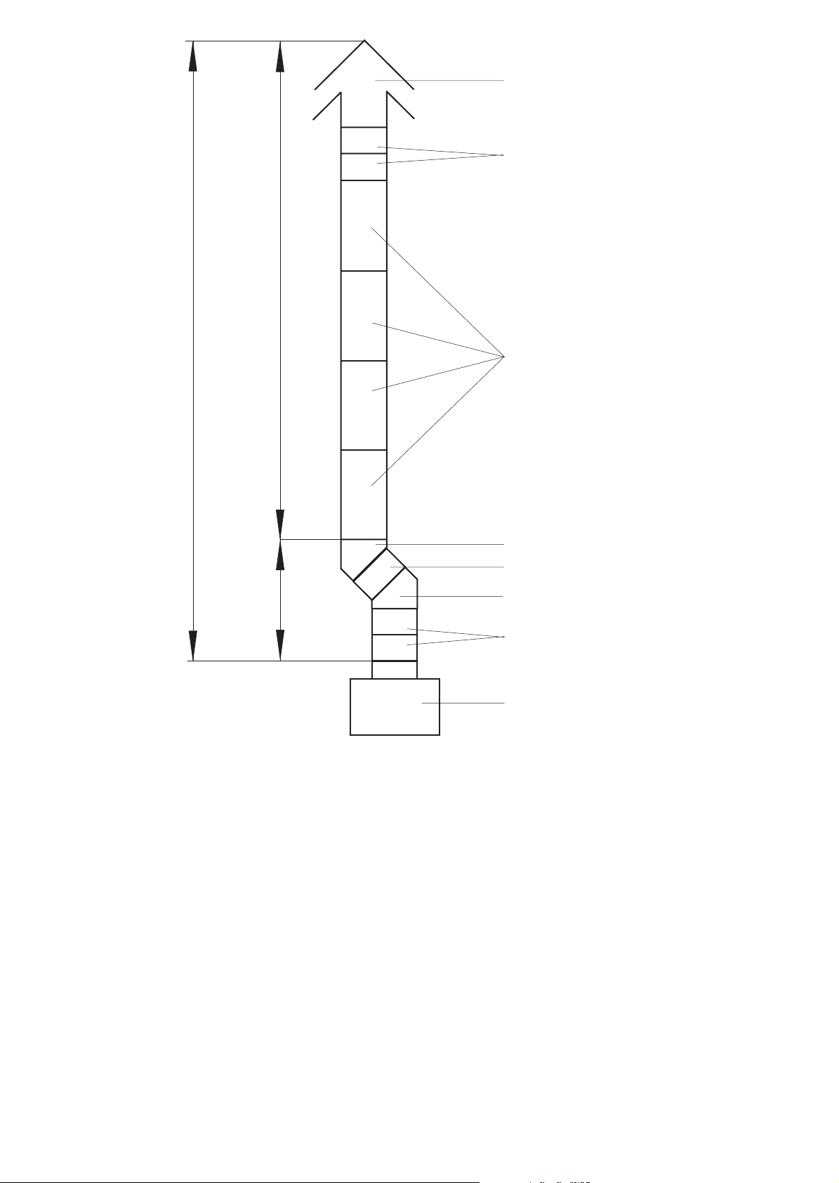
= 6.2m
H
a
Ridge T erminal
2 x 300 mm lengths
100 mm dia flue pipe
(Example only)
4.6m
4 x 1000 mm lengths
O
45
bend
300 mm length
O
45
1.6m
bend
2 x 300 mm lengths
Fig. 2
Flue spigot
W orked example of equivalent flue hight
Note: Ventilation of the compartment, room or internal space in which the appliance is to be installed must be checked for compli-
ance with the requirements of BS 5440 Part 2 ( Ref. Section 3 of these instructions) and upgraded as necessary
5.1.12 Consideration must be given to external flues with a view to prevention of condensation and weathering problems.
5.1.13 An approved terminal should always be used; a ridge terminal or “GC1” terminal is specifically recommended. The
latter should be positioned in a free air space where it is not shielded by any structure. A minimum of 1m (3ft.) from
any vertical or inclined roof structure must be allowed for.
5.1.14 Where flue blocks are used, builders should ensure that no obstruction is created during erection. The installer
should ensure that the connection flue does not project beyond the internal wall of the flue blocks and that there is
provision for examination and servicing.
5.1.15 Important: Before installing the appliance, carry out a visual check of the flue system as directed in the relevant
section of BS5440 Pt.1, then check the flue performance as follows:
a. close all doors and windows in the room in which the appliance is to be installed;
b. introduce some heat into the flue, using a blow torch or other means;
c. carry out a flow visualisation check with a smoke pellet at the intended position for the appliance. Ensure that
there is discharge of smoke from the correct terminal only, and no spillage into the room. Smoke coming out of
other than the correct terminal only, or a down draught or ‘no flow’ condition, indicates that the flue has failed
the test, and the appliance shall not be connected until the defect has been found and rectified, and the test
satisfactorily completed.
6
Page 7

5.2 ELECTRICAL
5.2.1 Mains.
a. The heater is supplied with mains cable (PVC sheathed, heat resisting to 85
2
Yellow, 6A, 0.75mm
), connected to a terminal block and exiting through the heater at the right hand top. The
cable is suitable for a 230V 50Hz supply and shall be connected to the fixed wiring using a double pole
switched, fused spur, incorporating a protective earth link. The fuse fitted shall be rated 5A to BS1362.
Connections shall be in accordance with the current edition of I.E.E Regulations BS 7671.
b. The Fan Delay Control and Limit Switch are not adjustable and are set as follows:
Basic Models: Fan Delay Control closes at 54OC± 4.5OC; opens at 40OC±3OC.
i.
All Models: Limit Switch opens at 80OC; closes at 60OC.
ii.
c. SYSTEM E-T MODELS: An electronic controller (Thermista-stat) is supplied which acts as a room thermostat.
d. BASIC CONTROL MODELS: A 24V room thermostat (not supplied), that complies with BS800, BS3955 and
BS4201 is essential to ensure close control of comfort conditions. An anticipator is located within the
thermostat and is graded in amps. The anticipator should be checked and adjusted to 0.2A.
5.2.2 Thermista-stat/Room Thermostat and its location.
a. The Thermista-stat/Room Thermostat should be located where there is free air circulation approx. 1.5m (5ft)
from the floor.
b. Avoid the following locations:
i. In a room where temperature is greatly affected by the sun or any other heat source, e.g. radiant fire,
wall light fittings or TV set.
o
C), 3-core Brown-Blue-Green/
ii. Near an outside door or windows, or on an outside wall.
iii. Where affected by warm air ducts, diffusers, waste pipes or the heater itself.
iv. Where subject to vibration.
c. Connect Thermista-stat/Room thermostat wires to control panel terminals ‘7’ and ‘8’ (see Fig. 7a/b or 8a/b).
5.2.3 IMPOR TANT: SUPERJAN 6 circulator .
a. If the air heater is fitted with a SUPERJAN 6 circulator, this will contain a pump overrun switch (CK6), which
is connected via the air heater terminal block terminals ‘6’, ‘10’ and ‘12’. Ensure that the red wire link
connecting terminals ‘10’ and ‘ 12’ has been removed, as this would cause the effective short circuit of the
pump overrun switch.
5.3 GAS (SEE BS5864 AND BS6891)
5.3.1 An independent gas supply pipe from the meter is to be preferred wherever possible. When this is not possible, the
pipe must be capable of taking the complete input of the heater and all other gas appliances being served by this
same pipe. This supply should be suitably sized to conform to British Standards requirements of no more than 1.0
mbar (0.4in wg) pressure drop (See table of discharge in BS6891).
5.4.2 The 1/2in union gas cock (supplied) must be fitted to the gas inlet of the heater for easy isolation during servicing.
The gas pipe should be so fitted and installed as to be durable, substantial and gas tight. To assist in determining
where a gas connection may not be tight, a leak detection fluid should be applied around the connection. Under no
circumstances should a flame be used to locate a gas leak. Gas entry to the air heater is through either side to a Rc1/2
(1/2in BSP . external [taper] thread).
5.4 DRAUGHT DIVER TER & DEFELCTOR PLATE:
5.4.1 The HI-SPEC J25 heater is supplied with a draught diverter that requires fitting to the rear of the heater prior to
installation, using 3 x 4mm screws and lock washers (provided).
5.4.2 The deflector plate prevents spillage from the draught diverter in the event of a leak between the air heater and the
base plemum and MUST be fitted as shown in fig 3 using the pre-drilled holes and the 2 x No8 screws provided.
5.5 DEFLECTOR PLA TE SAFETY CHECK:
In order to ensure that the deflector plate is preventing warm air from entering the draught diverter and therefore causing spillage,
the following test MUST be carried out BEFORE commissioning:
5.5.1 Turn on the power supply to the heater.
5.5.2 Set the summer airflow switch to “on”.
5.5.3 Using a smoke match, introduce smoke into the heat exchanger at the burner opening.
722
Page 8
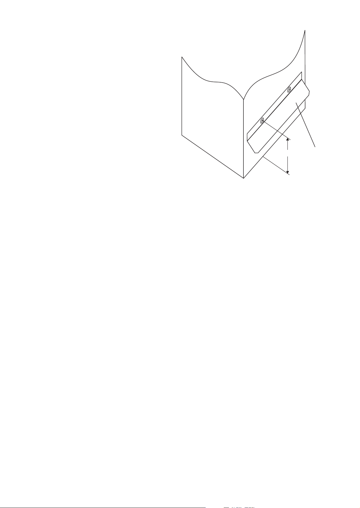
130mm
Heater
Deflector
Plate
EXTERNAL PROG.
OPTIONAL
NOCLOCK
OPTIONAL
Park S8 when no
water htr. or
for ext. prog.
N
C1
230V
N
WH
Timed
230V Cont.
AH(S5)
Timed
C2
C3
C5
S8
CH
WH
Park conns when no
clock fitted or for
external prog.
M
M
Spill
Switch
(TTB)
4
33
3
21
15
13
27
31
PCB
PCB
30
12
10
6
Wire colour code where indicated
*FELV FunctionalExtra-LowVoltage
NOTE:-
pink-----------pk
red------------r
blue----------b
black---------bk
brown--------br
white---------w
grey----------gy
orange-------or
violet---------v
yellow--------y
black/white------bk/w
green/yellow----g/y
N
N
N
N
CLOCK
230V
Continuous
C4
C2
C5
C1
C3
gy
gy
b
230V
Timed
PCB
PCB
22
PCB
29
PCB
br
w
br
bk
r
r
bk
br
If Superjan fitted removeredwire link
between terminals. 10 &12
br
or
S4
S6
S5
T
1
0
AIR
HTR.
230V
PUMP
r
r
br
S7
S9
S8
T
1
0
WATE R
HTR.
230V
(Optional)
(Optional)
(See note)
SW
Water
Htr.
A
18
14
17
r
bk
or
br
br
b
Multi-functional
Control
br
br
bk
Limit
Switch
Fan Delay
Control
M
N.BMay be
fittedwith start/run
capacitor.
Air
Fan
Fan power
cap.
230V
7
23
PCB
24
PCB
pk
bk
pk
pk
r
ON S3
N.BBreaking conn
starts fan
1
O
0
Summer Air
Flow
OFF S1
S2
th
Room
Thermista-stat
FELV *
Connections
8
33
32
31
30
29
28
27
26
25
24
23
22
2117
18
S1
8
19
20
S5
4
N
System E-T
PCB
Suppressed
230V Supply
Fan
Gas
Cleanflow
24V
Thermista-stat
FDC
L
N
2
1
L
N
GE
N.C
PCB
Power
Link
N
Timed
230V
Cont.
A
2
3
4
5
6
7
8
9
10
11
12
13
14
15
16
17
18
19
20
230V 50Hz
Supply
N
T3.15A
FUSE
br
b
br
MAINS
FILTER
1
L
br
N
N
T
L
N
24V
0V
GE
L
L
Room Thermista-stat
Water Heater
(Optional)
Water Pump
(Optional)
Limit Switch
Multi-functional
Control 230v
Fan Delay
Control
Cleanflow
(Optional)
TEST
R1
27K0
25 19
26
20
y
r
v
PCB
PCB
24V
0V
bk
(Optional)
Cleanflow
Air
Cleaner
N
(TTB)
Spill
Switch
5.5.4 Ensure that the smoke is drawn into the
heat exchanger and not blown back from
the burner opening.
5.5.5 If smoke is blown back from the burner
opening, check for air leaks between the
heater and the base plenum, paying
particular attention to the rear of the heater
directly beneath the draught diverter.
6. COMMISSIONING
6.1 PREP ARA TION:
6.1.1 Ensure that:
a. Gas and Electrical supplies are OFF.
6.2 SYSTEM BALANCING:
6.2.1 Set the Air Heater electrical supply ON.
6.2.2 Set the SUMMER AIRFLOW switch to ‘1’.
6.2.3 Balance the system to provide the required volume proportions at the warm air outlets.
Note: If the system includes ceiling diffusers, the air through these should be NOT LESS THAN 1.5m/s (300ft/min), except for very
small rooms, (i.e., bathrooms etc.). Outlet faces may require partial blanking in order to achieve this.
6.3 IGNITION OF PILOT AND MAIN BURNERS:
W ARNING: If the Pilot Bight is extinguished either intentionally or unintentionally, no attempt should be made to relight the gas
for a minimum of 3 minutes. Ensure that the Electrical supply, time contr ol and Selector switches are set to ‘OFF’.
6.3.1 Set the Thermista-stat/room thermostat to its lowest or OFF setting.
6.3.2 On the Multifunctional Control, remove the Outlet Pressure test point cover, and fit a pressure test gauge (refer fig.
6.3.3 Turn the heater Gas supply ON, test for gas soundness and purge the whole gas pipe as described in BS6891.
6.3.4 Referring to Fig. 5, partially depress the OPERA TING CONTROL and set the control
b. Filter, fan and fan compartments are free
from obstructions.
c. All registers or grilles are open and conform
to design specifications.
d. Return, relief and ventilation air
installations are adequate.
5).
‘SP ARK’ symbol. Press and hold the OPERATING CONTROL, and whilst observing the Pilot Burner, repeatedly
Note: If the Piezo unit should fail to spark, the Pilot Burner may be lit by applying a lighted taper to the Pilot Burner whilst the
OPERA TING CONTROL is pressed and held.
press the Piezo igniter button until the Pilot Burner ignites.
6.3.5 After 20 seconds release the OPERA TING CONTROL and let it spring out; ensure that the Pilot Burner remains
alight. If the Pilot Burner extinguishes, rotate the OPERATING CONTROL clockwise to the ‘l’ position and ensure
that the OPERATING CONTROL is fully reset. Wait three minutes and repeat steps 6.3.4 and 6.3.5, holding the
OPERA TING CONTROL depressed for a longer period, until the Pilot Burner remains alight.
6.3.6 With the Pilot Burner lit, depress the OPERATING CONTROL and turn it to the position indicated by the flame
symbol.
6.3.7 Ensure that the pilot flame envelops the thermocouple tip, if not, check that the pilot orifices and aeration port are
free from obstruction. The pilot is factory set and is non-adjustable.
6.3.8 Set the air heater Electricity supply ON.
6.3.9 Set the Time Control to the required Heating On periods.
6.3.10 Set the Selector switch to ‘TIMED’.
6.3.11 Set the Thermista-stat or room thermostat to MAXIMUM.
6.3.12 Ensure that the Main Burner has now ignited.
8 21
Deflector Plate
Fig. 3
1
/4 turn anti-clockwise to the
Page 9
6.3.13 T est for gas leakage at the supply,
Multifunctional Control, Pilot and Main
Burners using a proprietary detection
fluid, sealing any leaks found.
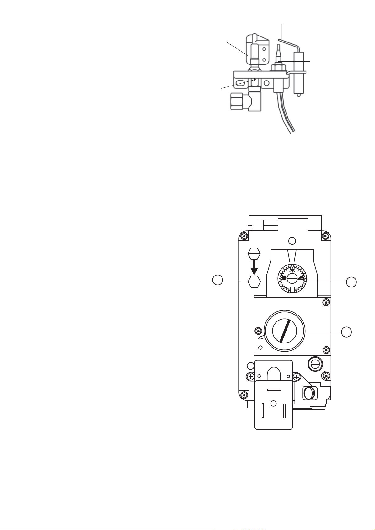
Electrode
Pilot Burner
6.3.14 Allow the heater to operate for a minimum
of 15 minutes to ensure stability.
6.4 MAIN BURNER PRESSURE TEST:
NOTE: AIR HEA TER BURNERS ARE FACTO RY SET
TO PROVIDE A NOMINAL HIGH RA TE OUTPUT AS
DET AILED IN SUB P ARA 1.2
6.4.1 Referring to Table 4 and Fig. 5 below,
ensure that the pressure test gauge
indicates the correct burner pressure,
resetting if required as follows:
At the Multifunctional Control:
i Remove the Burner Pressure
Adjuster cover.
ii. Set the Burner Pressure Adjuster
to provide a pressure test gauge indication for the correct burner pressure as detailed in Table 4.
iii. Refit the Burner Pressure Adjuster cover.
6.4.2 Apply the pressure set arrow to indicate the appropriate
burner pressure on the data badge.
6.5 EXTINGUISHING OF PILOT AND MAIN BURNERS:
6.5.1 On the Multifunctional Control, rotate the OPERATING
CONTROL clockwise to the ‘l’ position and ensure that
the OPERA TING CONTROL fully resets and both Pilot
and Main Burners are extinguished.
Thermocouple
Aeration Port
Fig. 4
Pilot Burner Assembly
6.5.2 On the Multifunctional control, remove the pressure test
gauge and refit the Outlet Pressure test point cover.
6.6 TEMPERATURE RISE CHECK:
6.6.1 Ignite the Pilot and Main Burners and allow 15 minutes
for stability before continuing.
6.6.2 Check that the temperature rise across the heater is
o
between 45
C - 55oC, setting the fan speed as follows:
i . SYSTEM E-T heaters: System E-T provides a fan
speed corresponding to the above temperature
rise, if the appliance is to be set to operate at the
minimum rate and the ducting has been sized
accordingly, set the ‘RATE SWITCH’ to ‘MIN’,
thus reducing the fan speed.
ii BASIC Control heaters, the fan speed is adjusted
by selecting the fan speed at control panel
(decrease voltage selection to decrease fan
speed).
Note: T apping 1 = 230V, T apping 2 = 220V , Tapping 3 = 210V ,
T apping 4 = 200V , T apping 5 = 190V , Tapping 6 = 170V .
6.7 AUTOMA TIC CONTROLS CHECK
6.7.1 Set the TIME CONTROL to ‘ON’.
6.7.2 Turn the Thermista-stat or room thermostat slowly
clockwise until the Main Burner ignites.
6.7.3 Ensure that the fan starts to operate after a short period
(approx. 1-2 minutes).
3
Sit
1
2
EV2
1. Operating control
2. Burner pressure adjuster
3. Outlet pressure test pont
Fig. 5
Multifunctional Control
920
Page 10

SYSTEM E-T models:
0.50
mbar
0.20
170V
190V
200V
210V
220V
In wg.
0.15
0.10
0.05
0.375
0.25
0.125
150
0.07
200
0.09
250
0.12
300 ft /min
0.14 m /sec
3
3
Air Volume
Air Volume
6.7.4 Ensure that the fan speed increases to full speed.
6.7.5 When the temperature reaches the control setting, check that the Main Burner cycles ON and OFF, at approximately
75 to 120 seconds.
BASIC CONTROL models:
6.7.6 When the temperature reaches the control setting, ensure that the Main Burner extinguishes followed by the fan
switching off after a short period.
6.7.7 When the temperature falls below the control setting, ensure that the Main Burner re-ignites followed by fan
operation.
6.8 SAFETY CHECKS:
6.8.1 Check for gas soundness within the appliance.
6.8.2 Spillage test: Carry out a full spillage test as follows, and ensure that the flue operates effectively with all doors
closed and any extractor fans in operation.
NOTE: If an extractor fan is situated in an adjoining or adjacent room, carry out the spillage test with the interconnecting doors
open.
If the draught diverter is accessible:
a. Introduce smoke into the draught diverter adjacent to an exit from the heat exchanger, by means a smoke
match or puffer.
b. Ensure that there is no spillage present (indicated by displacement of smoke downwards and out of the
draught diverter).
If the Draught Diverter is not accessible:
a. Introduce smoke, by means of part of a smoke pellet on a non-combustible support, into the heat exchanger.
b. Extinguish the Main and Pilot burners.
c. Ensure that there is no spillage evident by visually observing the draught diverter location on the air heater.
d. If spillage is evident, further investigation and rectification is required before re-testing the appliance.
W ARNING: The appliance shall not be left connected to the gas supply unless it has successfully passed the above spillage test.
6.8.3 Turn OFF the gas supply at the service cock and ensure that the Multifunctional Control fail-safe operates within 60
secs (indicated by loud click from Multifunctional Control).
6.8.4 Turn gas supply ON at service cock.
6.8.5 Switch the appliance electrical supply OFF.
6.8.6 Disconnect the Air Circulation Fan at the flying lead socket.
6.8.7 Switch the appliance electrical supply ON.
6.8.8 Ignite the Pilot and Main Burners as detailed in 6.3.1 to 6.3.5.
6.8.9 Ensure that the Limit Switch operates, indicated by the Main Burner extinguishing, within 120 and 180 seconds.
6.8.10 Switch the appliance electrical supply OFF.
6.8.11 Reconnect the Air Circulation Fan.
6.8.12 Switch the appliance electrical supply ON.
6.8.13 Ensure that the Main Burner re-ignites when the
appliance temperature reduces, (note: with the
Air Circulation Fan disconnected, there may be
some delay before the Main Burner re-ignites).
T able 5
Fan Performance Curve
Page 11

Low Rate Me dium Rate High Rate
kW MJ/h Btu/h kW MJ/h Btu/h kW MJ/h Btu/h
Inpu t
7.6 27.1 25,780 8.7 31.2 29,560 9.7 35.1 33,250
Output
5.6 20.0 19,000 6.5 23.2 22,00 7.3 26.4 25,000
Gas ra te C V
1037Btu/ft
3
0.70 m3/h (24.9ft3/h 0.80m3/h (28. 5ft3/h 0.91m3/h (32.1ft3/h
Burner s et ting
pressure (hot)
10.0 mbar (4.0 in wg) 14.0 mbar (5.6 in wg) 17.0 mbar (6.8 in wg)
Main injector BRAY CAT 33/700
T able 4
Main Burner Pressure Settings
7. INSTRUCTIONS FOR USERS
7.1 If the building is unoccupied, ensure that the Instructions for User are left taped to the air heater for the User, and the
Installation Instructions are left at or near the air heater for use on future service calls.
7.2 If the building is occupied, hand the User Instructions over and ensure the User understands:
7.2.1 How to ignite the pilot and burner.
7.2.2 How to operate the Thermista-stat/room thermostat, time and heater ON/OFF switch and summer air circulation
switch, and that the time control must be reset following a power failure.
7.2.3 How to extinguish the pilot and main burner at the Multifunctional control, and switch off electrical supply to the
heater.
7.2.4 How to remove, clean and refit the air filter and at what intervals (i.e. fortnightly, or for new houses, weekly).
7.2.5 How to control the heating system by opening and closing warm air outlets.
7.2.6 How to obtain summer air circulation.
7.2.7 That the air grilles on the heater or heater compartment; grilles and ventilators in the walls, windows or doors of the
building must not be obstructed.
7.2.8 That the heater must be serviced at least once a year by a competent person to ensure efficient and safe operation.
7.2.9 That the red instructions for safe use have been pointed out and understood.
8. MAINTENANCE
IMPORT ANT: Ensure that the gas and electricity supplies are isolated before commencing any maintenance or replacement of
components. After completion of any maintenance, always test for gas soundness and carry out a complete functional test of the
appliance in accordance with the Commissioning Instructions at Sect 6.1 to 6.8 inclusive.
8.1 ROUTINE MAINTENANCE:
Note: During annual servicing, ASD pilots must be inspected for damage to any component part, the aeration port and lint arrestor
must be cleaned to remove lint or debris. No attempt should to be made to clean ASD pilots with any hard tool that could result in
swarfe or foreign bodies, since this can block the pilot injector, thereby affecting the safety performance. Upon ignition, both pilot
flames should appear stable and ‘clean’, and the pilot assembly replaced if this is not so. If any damage is found, then the complete
pilot assembly will require replacement.
7.2.10 That expert help must be obtained if persistent failure of the pilot burner occurs.
8.1.1 Operate the appliance and check for the correct function of the burner and controls.
8.1.2 Turn OFF the gas and electrical supplies to the appliance.
8.1.3 Remove the air heater front panel.
8.1.4 Remove and check the return air filter/cleaner for cleanliness, remove and clean the Air Circulation fan as detailed in
para 8.7.
8.1.5 Remove the Burner and Controls Assembly as detailed in para 8.2. Inspect and clean the main burner and injector as
necessary. Examine the main burner for cracks, including hairline cracks, exchanging the burner as necessary.
8.1.6 Inspect and clear the Pilot Burner orifice.
1118
Page 12

8.1.7 Clean the heat exchanger flueways by thoroughly brushing from above and below.
8.1.8 By viewing through the Fan Aperture, and using a torch or similar, examine the heat exchanger externally for signs of
cracks or holes, particularly around welded joints.
8.1.9 Using a torch or similar, introduce a light source into the heat exchanger burner aperture and upper access port, and
again examine the heat exchanger for signs of cracks or holes, particularly around welded joints, whilst again viewing
through the Fan Aperture.
8.1.10 Refit the Air Circulation fan, Burner and Controls Assembly, and air filter/air cleaner.
8.1.11 Light the appliance and note the main burner flame profile. If the flame profile is af fected when the Air Circulation fan
switches on, check for any air leaks between the air heater and the base plenum, paying particular attention to
heaters with rear draught diverters. Rectify any air leaks before continuing with this procedure.
8.1.12 Allow the air heater to operate for approximately 15 minutes to ensure stability, and with the main burner lit, ensure
that the operation of Air Circulation fan does not affect the main burner flame profile.
8.2 BURNER AND CONTROL ASSEMBL Y REMOVAL:
8.2.1 E ns ur e t ha t t he Ga s a nd Electrical supplies are switched OFF
8.2.2 Remove the appliance door.
8.2.3 Disconnect the igniter at the Piezo unit.
8.2.4 Disconnect the Multifunctional Control electrical connections.
8.2.5 Disconnect the gas supply by breaking the union at the input side of the Multifunctional Control.
8.2.6 Slacken the 2 lower Burner Assembly securing screws.
8.2.7 Whilst supporting the Burner and Control Assembly , release the 2 upper Burner assembly fixing screws and
withdraw the Burner and Control Assembly
8.2.8 Refit the Burner and Control Assembly in reverse order.
8.3 BURNER AND CONTROL ASSEMBLY CLEANING:
8.3.1 Remove the Burner and Controls Assembly as detailed in 8.2.
8.3.2 Disconnect the Pilot Feed Pipe and Thermocouple from the Multifunctional Control.
8.3.3 Remove the lint arrestor from the Pilot Assembly, which is secured by a ‘Terry clip’.
8.3.4 Release the single screw securing the Pilot Assembly to the Burner and Controls Assembly, and remove the Pilot
Assembly.
8.3.5 Release the 3 nuts and lock washers securing the Main Burner to the mounting bracket, and remove the Main Burner.
8.3.6 Release the 2 nuts securing the burner back plate and gasket, and withdraw back plate and gasket from the burner.
8.3.7 Clean the burner thoroughly both inside and out with a soft brush. DO NOT ENLARGE, DISTORT OR DAMAGE
BURNER HOLES.
8.3.8 Reassemble in reverse order, replacing the burner gasket if damaged. The Pilot Assembly is located by a tag on the
burner bracket. DO NOT over tighten the Thermocouple connection at the Multifunctional Control, (finger tight plus
1 flat).
8.4 PILOT BURNER ASSEMBL Y REMOV AL AND REPLACEMENT:
Note: The relationship between the Pilot and Thermocouple is critical and must not be disturbed. Do not attempt to
dismantle the Pilot Assembly. If any part of the Pilot Assembly is considered defective, the complete assembly must
be replaced.
8.4.1 Remove the Burner and Controls Assembly as detailed in 8.2.
8.4.2 Disconnect the Pilot Feed Pipe and Thermocouple from the Multifunctional Control.
8.4.3 Remove the lint arrestor from the Pilot Assembly, which is secured by a ‘Terry clip’.
8.4.4 Release the single screw securing the Pilot Assembly to the Burner and Controls Assembly, and remove the Pilot
Assembly.
8.4.5 Disconnect the Pilot Feed Pipe from the Pilot Injector.
8.4.6 Refitting or replacement is in reverse order. The Pilot Assembly is located by a tag on the burner bracket. DO NOT
over tighten the Thermocouple connection at the Multifunctional Control, (finger tight plus 1 flat).
12 17
Page 13

8.5 MUL TIFUNCTIONAL CONTROL REMOV AL:
8.5.1 Remove the Burner and Controls Assembly as detailed in 8.2
8.5.2 Disconnect the Thermocouple at the Multifunctional Control, avoiding damage to the capillary.
8.5.3 Disconnect the Pilot Feed Pipe from the Multifunctional Control.
8.5.4 Disconnect Multifunctional Control input and output supply feeds.
8.5.5 Refitting or replacement is in reverse order.
NOTE: When refitting or replacing the Multifunctional Control, the ‘O’ ring seal is to be replaced.
8.6 PIEZO UNIT REMOV AL:
8.6.1 Disconnect the 2 conductors from Piezo unit.
8.6.2 Release the retaining nut and remove the Piezo unit from its mounting bracket.
8.6.3 Refitting or replacement is in reverse order.
8.7 AIR CIRCULATING FAN, REMOV AL AND CLEANING:
8.7.1 Ensure that the electrical supply is isolated.
8.7.2 Remove the appliance front door, release the 3 x securing screws and hinge down the fan chamber door.
8.7.3 Disconnect the fan flying leads from the Fan Assembly .
8.7.4 Release the Fan Assembly securing screw and withdraw the Fan Assembly from the Heater cabinet, avoiding damage
to the fan blades.
8.7.5 Remove all dust from both the impeller and motor, taking care to not disturb the balance of the fan.
8.7.6 Refitting or replacement is in reverse order.
8.8 ELECTRICAL ASSEMBL Y REMOVAL:
8.8.1 Ensure that the electrical supply is isolated.
8.8.2 Remove the appliance front door, release the 3 x securing screws and hinge down the fan chamber door.
SYSTEM E-T models:
8.8.3 Disconnect the following
a. Air circulation fan flying leads from the capacitor,
b. 230V mains ‘L’, ‘N’ and ‘E’ from connection block terminals ‘1’ and ‘2’, and Earth stud respectively ,
c. Thermista-stat connections from connection block terminals ‘7’ and ‘8’,
d. Limit switch from connection block terminals ‘13’ and ‘14’,
e. Fan Delay Control from connection block terminals ‘18’ and ‘17’,
f. Multifunctional Control from connection block terminals ‘16 (N) and ‘15’ (L),
g. W ater heater from connection block terminals ‘10’ (L) and ‘9’ (N),
h. W ater Pump from connection block terminals ‘12’ (L) and ‘11’ (N),
i. Cleanflow from connection block terminals ‘19’ (24V) and ‘20’ (0V),
. Earth lead from the fan chamber floor,
j
BASIC Control models:
8.8.4 Disconnect the following:
a. Air circulation fan flying leads from the Fan assembly,
b. 230V mains ‘L’, ‘N’ and ‘E’ from connection block terminals ‘1’ and ‘2’, and Earth stud respectively ,
c. Room thermostat connections from connection block terminals ‘7’ and ‘8’,
d. Limit Switch from connection block terminals ‘13’ and ‘14’,
e. Fan Delay Control from connection block terminals ‘18’ and ‘17’,
f. Multifunctional Control from connection block terminals ‘16 (N) ,‘15’ (L) and Earth stud.
g. W ater heater from connection block terminals ‘10’ (L) and ‘9’ (N),
h. W ater Pump from connection block terminals ‘12’ (L) and ‘11’ (N),
i. Cleanflow from connection block terminals ‘19’ (24V) and ‘20’ (0V),
j . Earth lead from the fan chamber floor,
Both model types:
8.8.5 Release the 2 x hinge pins and withdraw the Electrical Assembly , releasing wiring from cable clamps and grommets as
required.
8.8.6 Refitting or replacement is in reverse order.
13
Page 14

8.9 ELECTRONIC MODULE REMOV AL (SYSTEM E-T models only):
8.9.1 Ensure that the electrical is isolated.
8.9.2 R emov e the appl ianc e front door, release the 3 x securing screws and hinge down the fan chamber door.
8.9.3 Disconnect terminals ‘21’ to ‘33’ from the Electronic Module.
8.9.4 Release the 2 x screws and nuts securing the Electronic Module to the Electrical assembly and remove the module.
8.9.5 Refitting or replacement is in reverse order.
8.10 TRANSFORMER REMOV A L (BASIC Control models only):
8.10.1 Ensure that the electrical is isolated.
8.10.2 Remove t he ap plia nce f ront door, release the 3 x securing screws and hinge down the fan chamber door.
8.10.3 Disconnect the conductors from the large Transformer.
8.10.4 Relea s e t he 2 x screws and nuts securing the Transformer to the Electrical Assembly, and remove the Transformer.
8.10.5 Refitting or replacement is in reverse order.
8.11 TIME CONTROL and SWITCH REMOV AL:
8.11.1 Ensure that the electrical is isolated.
8.11.2 Remove t he ap plia nce f ront door, release the 3 x securing screws and hinge down the fan chamber door.
Time Control removal:
8.11.3 Disconnect conductors ‘C1’, ‘C2’, ‘C3’ and ‘C5’ from the Time control.
8.11.4 Release the 3 x fixing screws, and withdraw the Time control.
8.11.5 Refitting or replacement is in reverse order.
8.11.6 Set the Time Control to the required ON and OFF times.
8.11.7 Set the Time Control to the correct time.
Switch removal:
8.11.8 Disconnect the conductors from the switch terminals.
8.11.9 Depress the retaining clips and press the switch out of the fascia panel.
8.11.10 Refitting or replacement is in reverse order.
W ARNING: The fascia panel is held in place by push fit retainers which must be removed with caution to avoid causing damage to
the support pins. Removal of the fascia is not advised unless it is intended to be replaced.
8.12 F AN DELA Y CONTROL/LIMIT SWITCH REMOV AL:
8.12.1 Ensure that the electrical supply is isolated.
8.12.2 Remove appliance front door, release the 3 x securing screws and hinge down the fan chamber door.
8.12.3 Disconnect the following at the Electrical Panel:
a. Limit Switch from connection block terminals ‘13’ and ‘14’,
b. Fan Delay Control from connection block terminals ‘18’ and ‘17’,
c. Earth connection from common earth stud.
8.12.4 Release 2 x 4mm screws securing Limit switch mounting plate, and withdraw the control from the appliance by
drawing the conductors through the grommet in the fan chamber floor.
8.12.6 Refitting or replacement is in reverse order.
8.13 HE AT EXCHANGER ACCESS:
8.13.1 Ensure that the electrical supply is isolated.
8.13.2 Remove the appliance front door
8.13.3 Remove the Burner and Controls Assembly as detailed in sect 8.2.
8.13.4 Release the 6 screws securing the access plate to the bulkhead, and withdraw the access plate and gasket.
8.13.5 Release the 8 screws securing the top access cover plate, and withdraw the cover plate and gasket.
8.13.6 Reassembly is in reverse order.
NOTE: When reassembling, ensure that the baffles are pushed fully home, the gaskets are soundly sealed, and fully recommission the heater .
.
14 15
Page 15

9. DEFECT DIAGNOSIS
9.1 IMPORTANT: If an electrical defect occurs after installation of the appliance; preliminary earth continuity, polarity, and
resistance to earth checks should be carried out with a multimeter. On completion of any maintenance/fault-finding task that
has required the breaking and remaking of electrical connections, then checks of continuity, polarity, and resistance to earth
must be repeated.
9.2 WARNINGS:
9.2.1 When purging or checking gas supplies, ensure that the ventilation to the room or cupboard is adequate, and that all
naked lights are extinguished.
9.2.2 I f a defect occurs concerning the Pilot Burner, Thermocouple or Igniter Electrode, then the complete Pilot Assembly
MUST be replaced.
9.2.3 SYSTEM E-T models:
a. When carrying out any electrical testing, a test meter MUST be used, since low resistance test devices can cause
damage to the Electronics module.
b. Before commencing defect diagnosis, ensure that the Thermista-stat is set to maximum, mains supply is ‘ON’ and
that the time control is at an ‘ON’ position.
c. Care is to be taken during the replacement and handling of electronic assemblies (i.e. electronic panel, airflow sensor
or Thermista-stat). It is not practical to rectify defects on these assemblies, except at the manufacturer, and any
attempt to do so may render the guarantee or factory replacement arrangement invalid.
SYMPTOM POSSIBLE CAUSE REMEDY
a. Pilot will not light. i. No gas supply to heater. Check for gas at inlet pressure test
point on Multifunctional Control.
ii. Gas supply pipe not purged. Purge gas supply pipe in accordance
with BS 6891.
i ii Pilot orifice restricted. Clear pilot orifice or replace pilot assembly.
iv Pilot aeration port obstructed. Clear obstruction or replace pilot assembly.
v. Piezo system faulty. Check igniter, lead, and electrode.
vi. Excessive gas supply pressure. Check that mains gas pressure is 20mbar,
and reduce if necessary.
b. Pilot lights but goes i. Connection between thermo- Check connection is secure.
out on releasing START couple and Multifunctional
button during initial Control not secure.
light-up, or after
normal operation. ii. Faulty Multifunctional Replace Multifunctional Control.
Control.
iii. Faulty thermocouple. Replace Pilot Assembly.
iv. Pilot flame affected by draught. Eliminate draught.
v. Combustion air contaminated. Carry out spillage test and rectify.
c. Main burner opera- i. Gas rate or burner pressure Check gas rate and burner pressure
ting intermittently setting high. setting.
with fan running.
ii. Temperature rise excessive. Adjust fan speed or gas rate accordingly.
iii. Air filter or return air path Check filter is clean and air path is clear.
restricted.
iv. Excessive number of outlets Open additional outlets.
closed.
SYSTEM E-T models:
d. Incorrect operation Fault related to SYSTEM E-T Consult diagnostic chart and follow
of fan or main burner. Control system (refer to pages 18-21) recommended procedure.
Basic control models:
e. Pilot alight but main i. Mains electrical supply not Check mains supply.
burner not igniting. connected to heater.
Page 16
ii. Controls not demanding heat Check that time control and
room thermostat are operating correctly.
iii. T3.15A fuse failed. Replace. If failure occurs again, check
wiring for short circuits.
iv. Loose connection to room thermo- Check connections.
stat, limit switch, gas control lead,
time control, or transformer.
v. 230V/24V transformer failure. Check 24V side with test meter, if voltage
missing, replace transformer.
vi. Faulty relay module Check 230V at white wire from switch S5
vii. Multifunctional Control faulty. Replace Multifunctional Control.
viii.Limit Switch faulty. Short circuit control and replace if necessary.
ix. Room thermostat or external Fit temporary loop in heater thermostat
wiring faulty. socket. If heater ignites, external circuit
or room thermostat is faulty.
f. Main burner lights i. Loose electrical connection Check connections.
but fan fails to run at fan control.
after approx. 3 min.
ii. Fan Delay Control faulty. Replace.
iii. Faulty fan assembly. Replace, taking care not to damage
impeller
.
iv. Burner pressure setting incorrect. Adjust pressure as necessary.
g. Main burner opera- i. Gas rate or burner pressure Check gas rate and burner pressure
ting with intermittent setting too low. setting.
fan operation.
ii. Fan Delay Control faulty Replace.
h. Noisy operation. i. Gas pressure too high. Check burner pressure setting.
ii. Noisy fan motor. Replace fan assembly.
iii. Fan speed setting too high. Adjust fan speed.
i. Fan runs for excessive i. Fan delay control faulty. Replace.
period or operates
intermittently after
main burner shuts down.
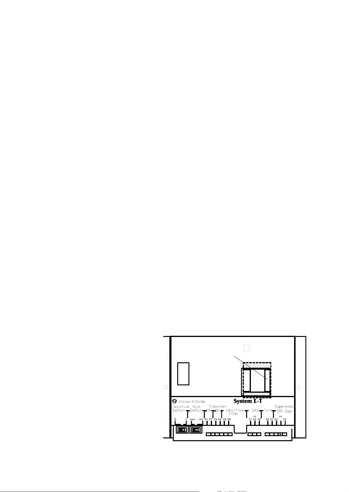
9.3 The SYSTEM E-T module is fitted with a diagnostic light emitting diode (LED) which is visible through a hole in the
module cover, as shown in Fig. 5 below. If the LED is flashing, this means that :
9.3.1 The fan is not connected, or
9.3.2 The capacitor is not connected, or
9.3.3 There is a short circuit in the fan supply.
Diagnostic LED
16
Fig. 6
SYSTEM E-T Electronic Module
Page 17
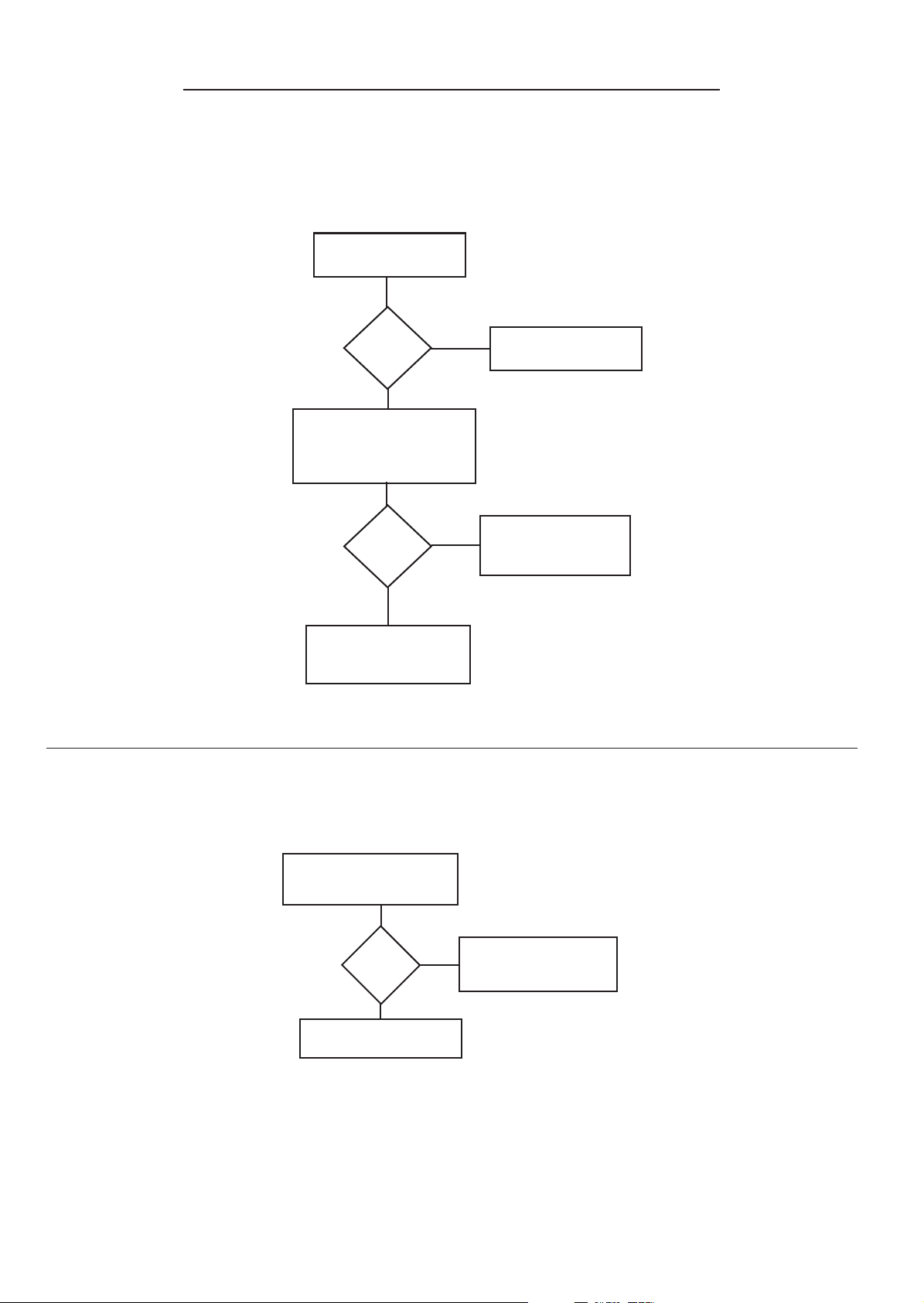
SYSTEM E-T DEFECT DIAGNOSTIC FLOW CHART
MAIN BURNER NOT CYCLING
(ROOM TEMPERA TURE TOO HIGH)
DISCONNECT
THERMISTA-ST A T
DOES
BURNER
GO OUT?
N
DISCONNECT
MUL TIFUNCTIONAL
CONTROL A T
TERMINAL 15
DOES
BURNER
GO OUT?
N
REPLACE
MUL TIFUNCTIONAL
CONTROL
Y
REPLACE
THERMISTA-ST A T
Y
REPLACE
ELECTRONICS
MODULE
F AN CONTINUES T O RUN, OR CYCLES AFTER HEA TING IS TURNED OFF
DISCONNECT
TERMINALS ‘17’ &’18’
DOES
FAN
RUN?
Y
N
REPLACE FAN DELA Y/
LIMIT CONTROL
REPLACE
ELECTRONIC
MODULE
Page 18
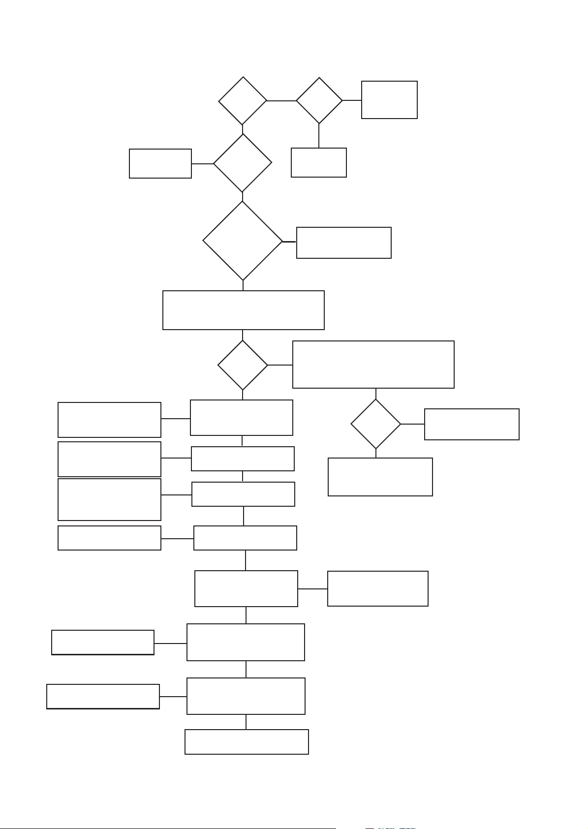
MAIN BURNER NOT OPERATING
Low Rate Me dium Rate High Rate
kW MJ/h Btu/h kW MJ/h Btu/h kW MJ/h Btu/h
Inpu t
7.6 27.1 25,780 8.7 31.2 29,560 9.7 35.1 33,250
Output
5.6 20.0 19,000 6.5 23.2 22,00 7.3 26.4 25,000
Gas ra te C V
1037Btu/ft
3
0.70 m3/h (24.9ft3/h 0.80m3/h (28. 5ft3/h 0.91m3/h (32.1ft3/h
Burner s et ting
pressure (hot)
10.0 mbar (4.0 in wg) 14.0 mbar (5.6 in wg) 17.0 mbar (6.8 in wg)
Main injector BRAY CAT 33/700
SWITCH ON
REPLACE
MUL TIFUNCTIONAL
CONTROL
CHECK WIRING TO
MUL TIFUNCTIONAL
CONTROL
LINK TERMINALS ‘13’
& ‘14’, IF BURNER
LIGHTS REPLACE
FAN/LIMIT CONTROL
CHECK WIRING
CONNECTIONS
IS
PILOT
LIT?
Y
IS 230V
N
230 V
SUPPLY
ON ?
Y
IS TIME
CONTROL &
THERMISTA-STAT
CORRECTL Y
SET?
Y
DISCONNECT THERMISTA-ST AT AT
TERMINALS ‘7’ & ‘8’, LINK
TERMINALS ‘7’ & ‘TEST’
DOES FAN
RUN?
Y
N
CHECK FOR 230V A T
Y
MUL TIFUNCTIONAL
CONTROL
N
Y
CHECK FOR 230V A T
TERMINAL 15
N
Y
CHECK FOR 230V A T
TERMINAL 13
N
Y
CHECK FOR 230V A T
TERMINAL 29
N
IS
GAS
ON ?
N
TURN GAS
ON
Y
LIGHT
PILOT
N
SET CONTROLS
CORRECTL Y
RECONNECT THERMISTA-ST AT AT
TERMINALS ‘7’ & ‘8’,
DISCONNECT ON CONNECTION A T
THERMISTA-ST A T
DOES
FAN
RUN?
N
EXTERNAL WIRING TO
THERMISTA-STA T
FAUL TY
Y
REPLACE
THERMISTA-STAT
N
CHECK FOR 230V A T
TERMINAL 27
N
CHECK FOR 230V A T
CENTRE TERMINAL OF
SWITCH ‘S5’
N
CHECK FOR 230V AT TIME
CONTROL
TERMINAL ‘C5’
CHECK WIRING
CONNECTIONS
REPLACE AIR HEATER
SWITCH
Y
Y
N
REPLACE TIME
CONTROL MECHANISM
Y
REPLACE
ELECTRONIC
MODULE
Page 19
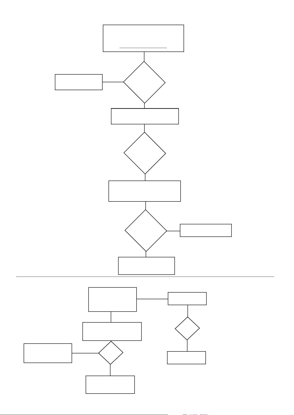
FAN OPERA TES BUT BURNER CYCLES BEFORE REQUIRED TEMPERATURE IS REACHED
DISCONNECT THERMISTA-ST AT AT
TERMINALS ‘7’ & ‘8’, LINK
TERMINALS ‘7’ & ‘TEST’
DO NOT LINK ‘7’ &’8’
DOES
REPLACE
THERMISTA-STAT
N
THE BURNER
CONTINUE TO
CYCLE?
Y
CHECK RETURN AIR P ATH
FOR RESTRICTIONS
DOES
THE BURNER
CONTINUE TO
CYCLE?
Y
CHECK TEMPERATURE RISE. IF
O
LESS THAN 60
C, LINK
TERMINALS ‘13’ & ‘14’
DOES
THE BURNER
CONTINUE TO
N
REPLACE FAN DELA Y/
LIMIT CONTROL
CYCLE?
Y
REPLACE
ELECTRONIC MODULE
MAIN BURNER ON BUT FAN NOT RUNNING
CHECK FOR
VOL TAGE A T
TERMINALS 30 & 31
N
BRIDGE OUT
F AN DELAY A T
TERMINALS 21 & 22
Y
REPLACE
CAPACITOR
DOES
FAN
START?
REPLACE FA N
DELA Y/LIMIT
CONTROL
Y
REPLACE
ELECTRONICS
DOES
FAN
START?
N
MODULE
N
REPLACE
FAN
1910
Page 20
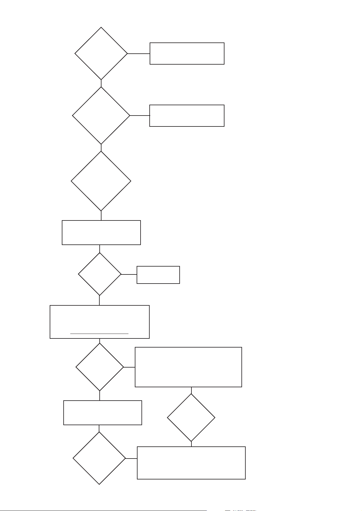
FAN RUNS BUT MAIN BURNER NOT OPERATING
IS
‘SUMMER
AIRFLOW’
SWITCH
SET TO
‘0’
Y
IS
THERMISTA
-STAT
CONNECTED
Y
IS
THERMISTA
-STAT SET
TO SUMMER
AIRFLOW
N
N
SET ‘SUMMER
AIRFLOW SWITCH TO
‘0’
CONNECT
THERMISTA-ST A T
Y
SET THERMISTA-ST AT TO
REQUIRED
TEMPERATURE SETTING
DOES
FAN STILL
RUN ?
Y
DISCONNECT THERMISTA-ST AT AT
TERMINALS ‘7’ & ‘8’, LINK
TERMINALS ‘7’ & ‘TEST’
DO NOT LINK ‘7’ &’8’
DOES
FAN STILL
RUN WITH
BURNER
LIT?
N
CHECK THERMISTA-ST AT WIRING . IF
OK, REPLACE THERMISTA-ST AT . IF
N
NOT , RECONNECT TERMINALS ‘7’ &
FAULT
CLEARED
‘8’, AND SET THERMISTA-STA T TO
DEMAND HEAT
Y
REPLACE ELECTRONIC
MODULE. RECONNECT
THERMISTA-ST A T
HAS
FAN STOPPED
AND BURNER
LIT?
Y
HAS
BURNER
LIT?
Y
F AN OPERA TES AFTER BURNER HAS
RAISED THE INTERNAL
TEMPERA TURE TO CAUSE THE F AN
DELA Y CONTROL TO OPERA TE
Page 21
EXTERNAL PROG.
OPTIONAL
NOCLOCK
OPTIONAL
Park S8 when no
water htr. or
for ext. prog.
N
C1
230V
N
WH
Timed
230V Cont.
AH(S5)
Timed
C2
C3
C5
S8
CH
WH
Park conns when no
clock fitted or for
external prog.
M
M
Spill
Switch
(TTB)
4
33
3
21
15
13
27
31
PCB
PCB
30
12
10
6
Wire colour code where indicated
*FELV FunctionalExtra-LowVoltage
NOTE:-
pink-----------pk
red------------r
blue----------b
black---------bk
brown--------br
white---------w
grey----------gy
orange-------or
violet---------v
yellow--------y
black/white------bk/w
green/yellow----g/y
N
N
N
N
CLOCK
230V
Continuous
C4
C2
C5
C1
C3
gy
gy
b
230V
Timed
PCB
PCB
22
PCB
29
PCB
br
w
br
bk
r
r
bk
br
If Superjan fitted removeredwire link
between terminals. 10 &12
br
or
S4
S6
S5
T
1
0
AIR
HTR.
230V
PUMP
r
r
br
S7
S9
S8
T
1
0
WATE R
HTR.
230V
(Optional)
(Optional)
(See note)
SW
Water
Htr.
A
18
14
17
r
bk
or
br
br
b
Multi-functional
Control
br
br
bk
Limit
Switch
Fan Delay
Control
M
N.BMay be
fittedwith start/run
capacitor.
Air
Fan
Fan power
cap.
230V
7
23
PCB
24
PCB
pk
bk
pk
pk
r
ON S3
N.BBreaking conn
starts fan
1
O
0
Summer Air
Flow
OFF S1
S2
th
Room
Thermista-stat
FELV *
Connections
8
33
32
31
30
29
28
27
26
25
24
23
22
2117
18
S1
8
19
20
S5
4
N
System E-T
PCB
Suppressed
230V Supply
Fan
Gas
Cleanflow
24V
Thermista-stat
FDC
L
N
2
1
L
N
GE
N.C
PCB
Power
Link
N
Timed
230V
Cont.
A
2
3
4
5
6
7
8
9
10
11
12
13
14
15
16
17
18
19
20
230V 50Hz
Supply
N
T3.15A
FUSE
br
b
br
MAINS
FILTER
1
L
br
N
N
T
L
N
24V
0V
GE
L
L
Room Thermista-stat
Water Heater
(Optional)
Water Pump
(Optional)
Limit Switch
Multi-functional
Control 230v
Fan Delay
Control
Cleanflow
(Optional)
TEST
R1
27K0
25 19
26
20
y
r
v
PCB
PCB
24V
0V
bk
(Optional)
Cleanflow
Air
Cleaner
N
(TTB)
Spill
Switch
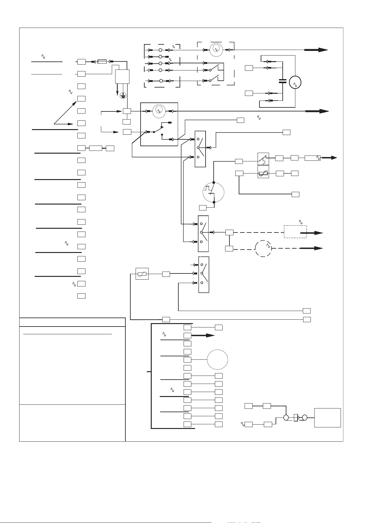
Fig. 7a System ET
Functional Diagram
Page 22
EXTERNAL PROG.
OPTIONAL
NO CLOCK
OPTIONAL
Park S8 when no
water htr. or
for ext. prog.
N
C1
230V
N
WH
Timed
230V Cont.
AH(S5)
Timed
C2
C3
C5
S8
CH
WH
Park conns when no
clock fitted or for
external prog.
M
M
4
18
14
12
19
7
8
15
230V
Multi-functional Control
20
10
6
Wire colour code where indicated
*FELV Functional Extra-LowVoltage
pink----------pk
red-----------r
blue---------b
black-------bk
brown------br
white-------w
grey-------gy
orange---or
violet------v
yellow-----y
black/white------bk/w
purple/red-------p/r
green/yellow----g/y
N
N
N
N
N
N
N
CLOCK
230V
Continuous
C4
C2
C5
C1
C3
Link
gy
gy
b
r
bk
w
w
br
br
or
or
br
br
bk
p/r
p/r
y
r
y
v
r
bk
bk
br
b
w
or
r
r
r
r
bk
T3.15A
FUSE
br
br
S4
S6
S5
T
1
0
AIR
HTR.
S7
S9
S8
T
1
0
WATER
HTR.
L
Voltage
Selector
TX2
TX1
Summer
Air Flow
S3
ON
S1
OFF
S2
1
0
0
Limit
Switch
Fan Delay
Control
Fan
24V
0V
(Optional)
SW
Comm.
n/o
24V
Cleanflow
Air
Cleaner
T500mA
Relay Module
1
2
3
4
5
6
7
8
9
10
11
12
13
14
15
16
17
18
19
20
230V 50Hz
Supply
TIMED
230V
Cont.
L
N
N
N
N
T
L
N
24V
0V
GE
L
L
Room Thermostat
Water Heater
(Optional)
Water Pump
(Optional)
Limit Switch
Multi-functional
Control 230v
Fan Delay
control
Cleanflow
(Optional)
A
24V Thermostat
(Not Fitted)
FELV * Connection
13
r
br
17
230V
PUMP
230V
(Optional)
Water
Htr
N
L
N
(Optional)
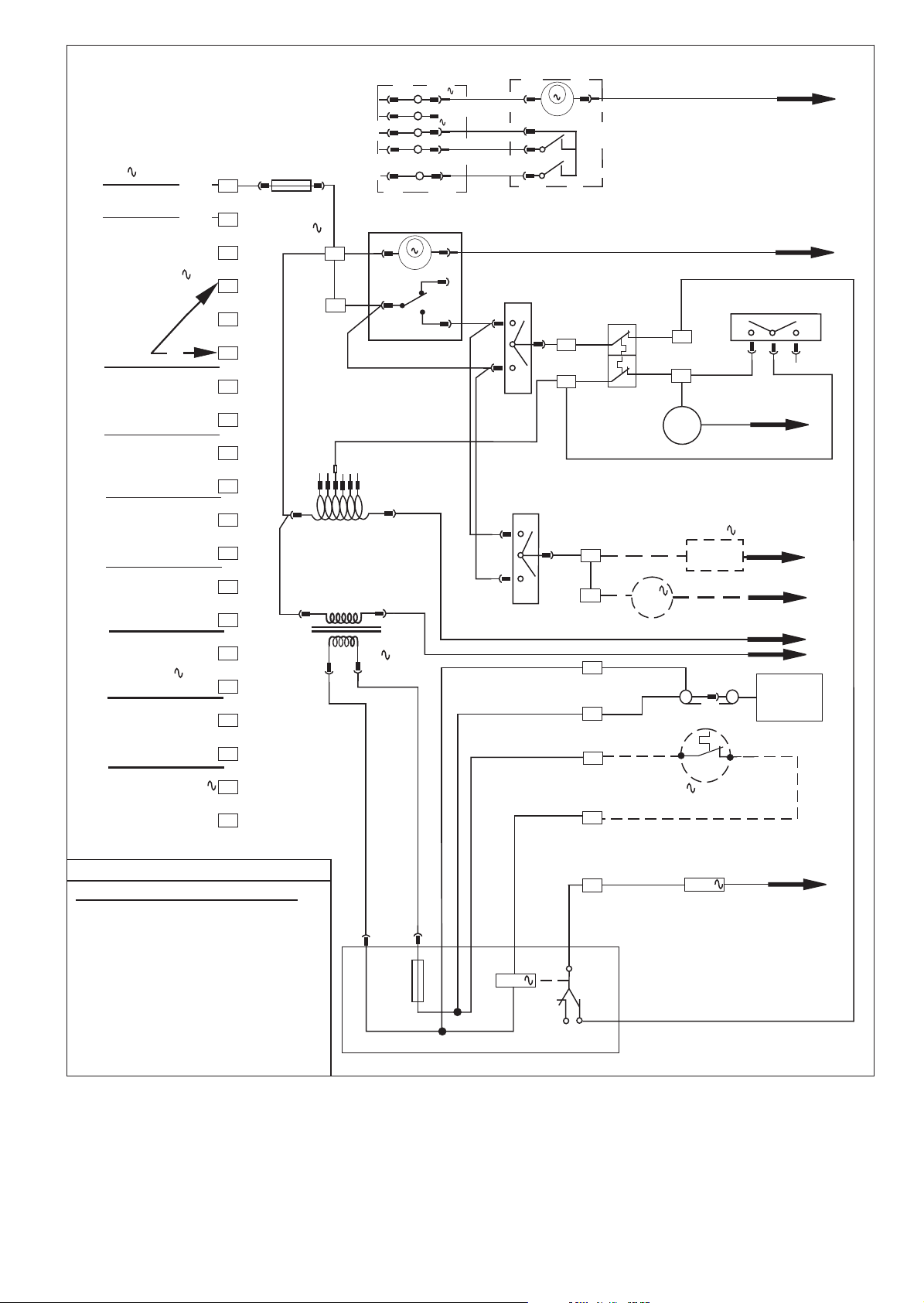
Fig. 7b Basic Control
Functional Diagram
Page 23
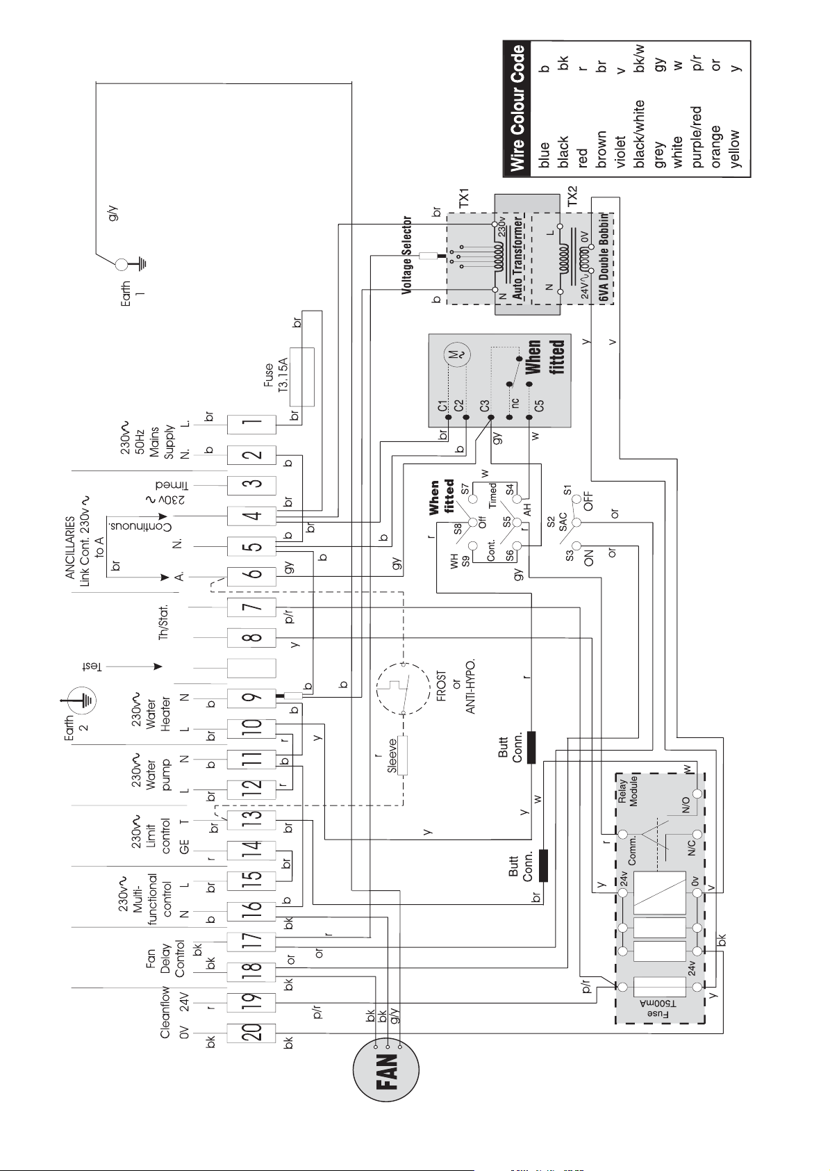
Fig. 8a
System ET Circuit Diagram
23
Page 24
20 19 18 17 16 15 14 13 12 11 10 9
87 654 32
1
bk bk bbrr
br
br brb b
bk
0V NL LNLNGE T
24V
r
Cleanflow
Fan
Delay
Control
230v
Multi-
functional
control
230v
Limit
control
230v
Water
pump
230v
Water
Heater
230v
50Hz
Mains
Supply
Th/Stat.
230v
Timed
Test
br
br
Earth
1
Earth
2
ANCILLARIES
Link Cont. 230v
to A
A.
N.
N. L.
Continuous.
Fuse
T3.15A
g/y
p/r
or
or
bkbkbk
b
r
r
b
b
b
y
y
y
y
y
bk
v
w
r
p/r
w
r
or
v
y
or
ON
OFF
r
y
bbr
b
b
b b
p/r
gy
gy
br
br
br
r
br
br
br
r
Sleeve
FROST
or
ANTI-HYPO.
Issue 02
Wire Colour Code
blue ----b black -----bk red ----r
brown ---br violet ---v black/white ---bk/w
grey ----gy white ----w purple/red ---p/r
orange ---or yellow ----y
b
Butt
Conn.
Butt
Conn.
TTB
TTB
WH
S9
AH
S8
S7
Cont.
Off
When
fitted
Timed
r
gy
S6
S3
S5
S2
SAC
S4
S1
w
w
nc
C5
When
fitted
gy
C3
b
C2
br
br
Voltage Selector
b
C1
M
Fuse
T500mA
24v
0v
24v
Relay
Module
N/C
N/O
Comm.
TX1
TX2
24V
0V
L
N
230v
N
6VA Double Bobbin
Auto Transformer
g/y
bk
bk
FAN
Component Internal Size (mm) Re s istance Components Internal Size (mm) Re s is tance
Flue Blocks
197 x 67 0.85 per metre
45
o
bend
100mm pipe 0.61 per fitting
231 x 65 0.65 run 125mm pipe 0.25 per fitting
317 x 63 0.35 150mm pipe 0.12 per fitting
140 x 102 0.60 197 x 67 0.30 per fitting
200 x 75 0.60 231 x 65 0.22 per fitting
183 x 90 0.45 317 x 63 0.13 per fitting
Pipe
100 0.78 Raking Block Any 0.30 per block
125 0.25
150 0.12 Adaptor Block Any 0.50 per block
C himney 2 1 3 x 21 3 0.0 2
Terminal
100mm ridge 2.5
125mm ridge 1.0
90
o
Bend
100mm pipe 1.22 per fitting 150mm ridge 0.48
125mm pipe 0.50 per fitting 100mm GCI 0.6
150mm pipe 0.24 per fitting 125mm GCI 0.25
150mm GCI 0.12
Appliance Inlet Resistance ( Ki) Flue Out let res is t ance (Ko)
100mm Dia Spigot 2.5 100mm 2.5
125mm Dia Spigot 1.0 125mm 1.0
150mm Dia Spigot 0.48 150mm 0.48
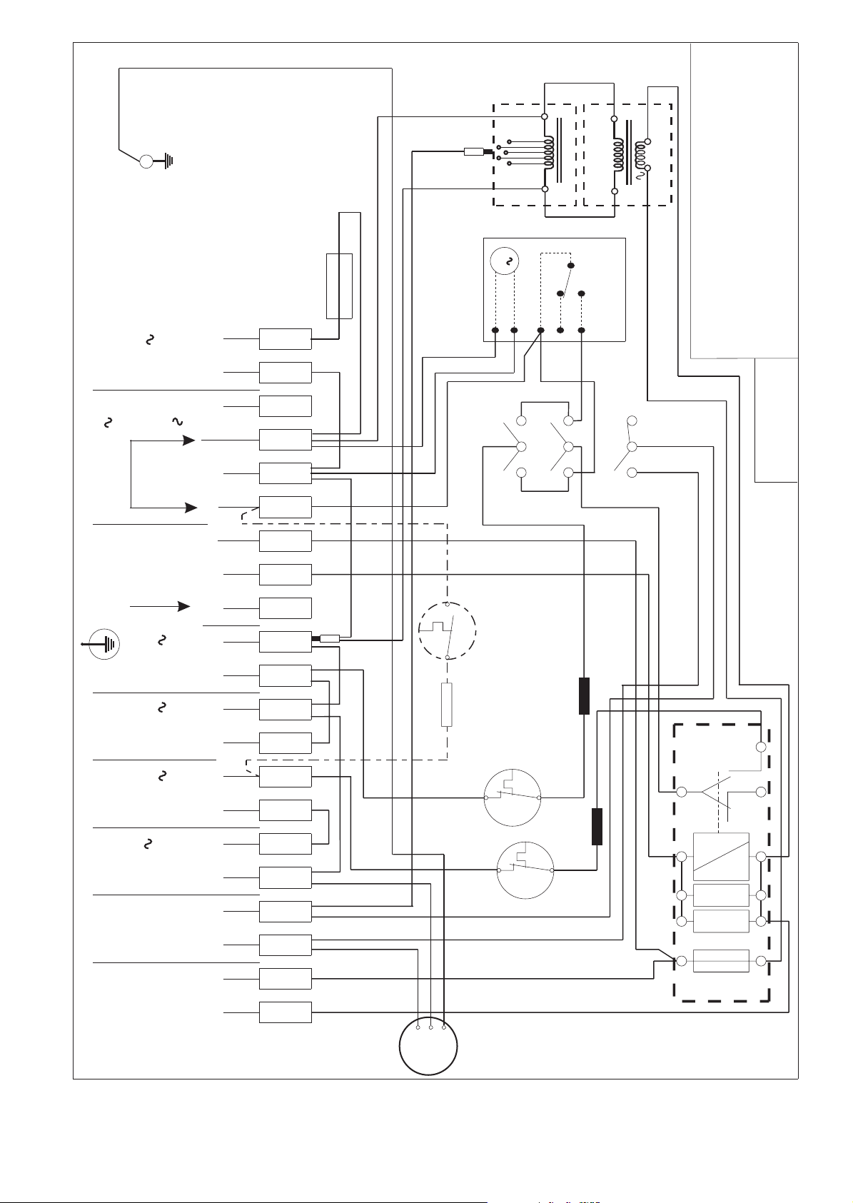
Fig. 8b
Basic Control Circuit Diagram
24 5
Page 25
SIDE VIEW
BASE V IEW
FRONT VIEW
TOP VIEW
9
9
5
326088
300
51
2065010
254
376
120 dia.
90
440
695
3
0
0
3
8
4
1
3
2
5
6
2
2
1
0
253
21
393
115
3
9
3
5
1
2
593
60067
0
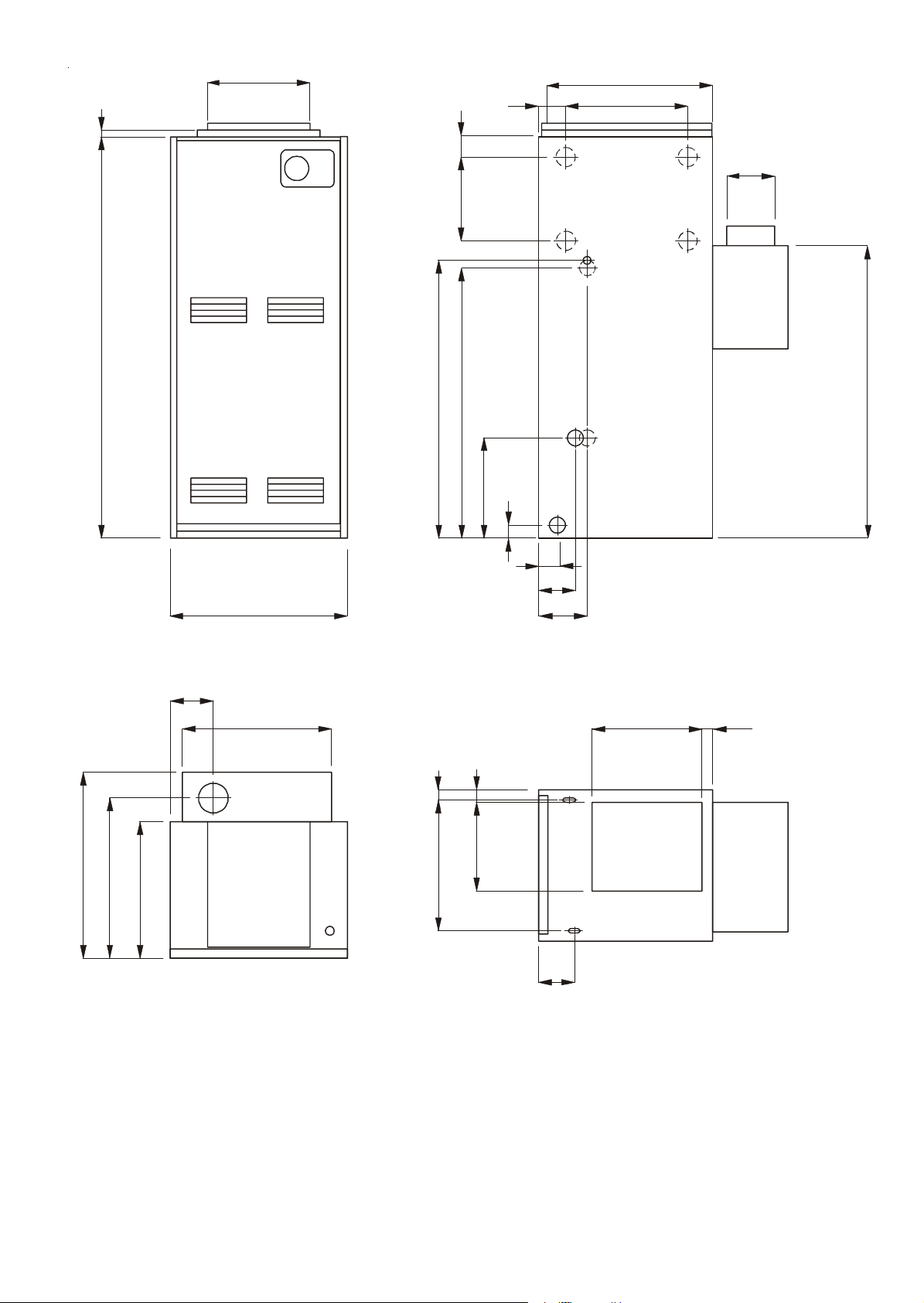
Fig. 9
Principal Dimensions
254
Page 26
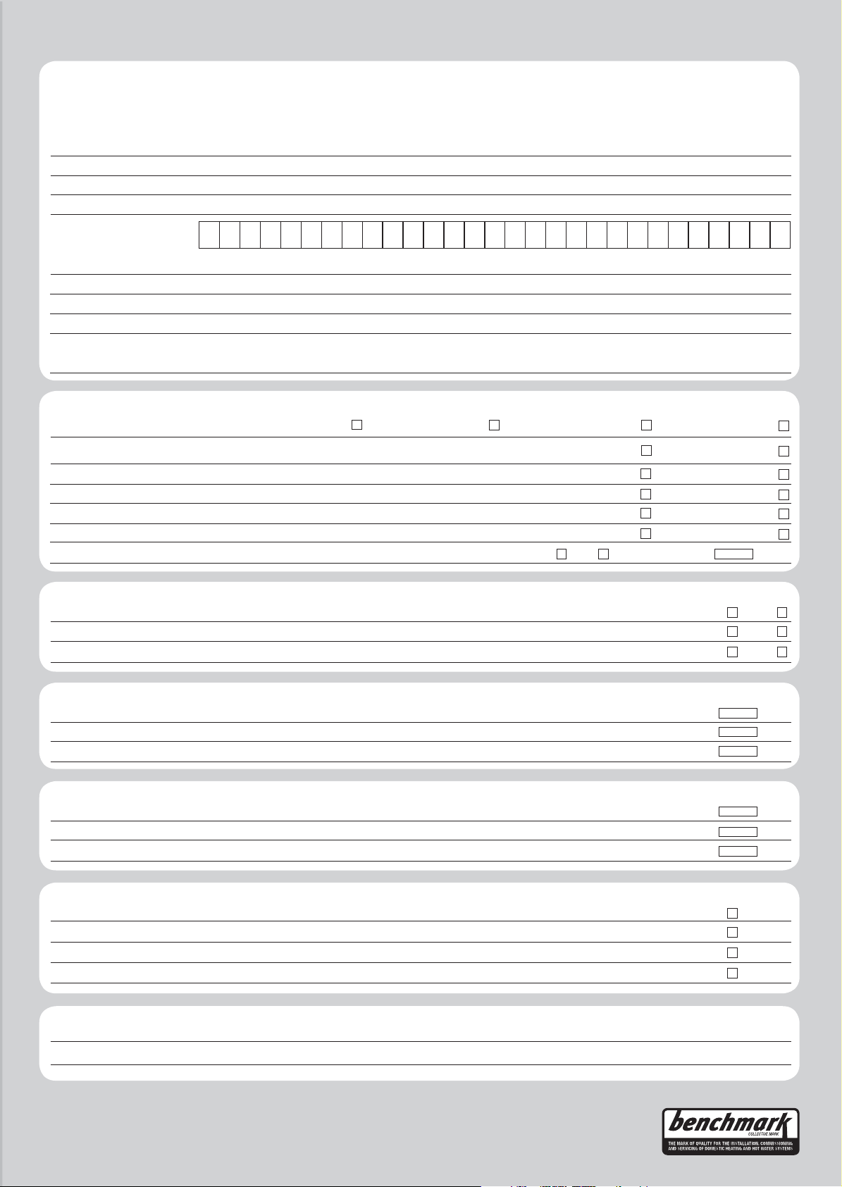
WARM AIR HEATER AND CIRCULATOR COMMISSIONING CHECKLIST
Ven ti la t e d fro m i ns id e
building.
Low leve l g r ille 2 84c m
2
(44in2)
Hig h leve l g r ille 142 cm
2
(22in2)
Ven t i la t e d fro m
o utside bu ild in g .
Low leve l g r ille 142c m
2
(22in2)
Hig h leve l g r ille 7 1cm
2
(112)
This Commissioning Checklist is to be completed in full by the competent person who commissioned the warm air unit and associated equipment as a means of
demonstrating compliance with the appropriate Building Regulations and then handed to the customer to keep for future reference.
Failure to install and commission this equipment to the manufacturer’s instructions may invalidate the warranty but does not affect statutory rights.
Customer Name
Address
Telephone Number
Warm Air Unit Make and Model
Warm Air Unit Serial Number
Commissioned by (print name) Gas Safe Reg. No.
Company Name Telephone No.
Company Address
Commissioning Date
To be completed by the customer on receipt of a Building Regulations Compliance Certificate*:
Building Regulations Notification Number
CONTROLS Tick the appropriate boxes if applicable
Time & Temperature Room Thermostat & Programmable Load/Weather Optimum Start
Control to Heating Programmer/Timer Roomstat Compensation Control
Time & Temperature Cylinder Thermostat & Warm Air
Control to Hot Water Programmer/Timer Unit
Heating Zone Valves Fitted Not Required
Hot Water Zone Valves Fitted Not Required
Thermostatic Radiator Valves Fitted Not Required
Automatic Bypass System Fitted Not Required
Warm Air Unit Interlock Yes No If YES, Volume Litres
(if applicable)
FOR WARM AIR HEATERS ONLY
Has the system been balanced in accordance with the heater manufacture’s instructions? Yes No
Was an anemometer used? Yes No
Have balancing dampers been fitted? Yes No
FOR WARM AIR HEATING: MEASURE AND RECORD
Burner operating pressure mbar
Heat input kW
Temperature difference between return air inlet and nearest outlet °C
FOR HOT WATER GENERATORS: MEASURE AND RECORD
Burner operating pressure mbar
Heat input kW
Water flow temperature °C
ALL INSTALLATIONS
The heating and hot water system complies with the appropriate Building Regulations Yes
The system and associated products have been installed and commissioned in accordance with the manufacturer’s instructions Yes
The efficient operation of system and its controls have been demonstrated to and understood by the customer Yes
The manufacturer’s literature, including Benchmark Checklist and Service Record, has been explained and left with the customer Yes
Commissioning Engineer’s Signature
Customer’s Signature
(To confirm demonstration of equipment and receipt of appliance instructions)
* All installations in England and Wales must be notified to Local Authority Building Control (LABC) either directly or through a Competent
Persons Scheme. A Building Regulations Compliance Certificate will then be issued to the customer.
© Heating and Hotwater Industry Council (HHIC)
www.centralheating.co.uk
Page 27
Page 28

Johnson
& Starley
10. SHORT LIST OF SPARES
HI-SPEC J25
KEY G.C No MFR’S No DESCRIPTION QTY
1 232 878 BOS 02064 Fan Assembly 1
2 381 627 1000-0701140 Multifunctional Control (S.I.T. Nova) 1
3 379 837 1000-0704250 Pilot Assembly (S.I.T .) 1
4 378 466 BOS 02031 Time Control 1
5 245 503 T193-0751000 Burner Assembly 1
6 398 388 BOS 02060 Main Injector (Bray 33/700) 1
7 395 945 1000-0701160 Piezo Unit (High Energy) 1
8 245 509 1000-0513820 Fuse T3.15A anti-surge 1
9 T193-0145000 Filter Tray 1
10 364 835 S00832 Solenoid Valve 1
11 242 228 S00174 Heat Exchanger 1
12 245 542 1000-0515970 Capacitor 15 uF 1
System E-T Models only
13 245 510 ET 001 Electronic Panel Assembly with daughter board 1
14 245 514 1000-0515620 Thermista-stat 1
15 245 515 1000-0515455 Fan Delay/Overheat (limit) switch 1
16 1000-0515090 Mains Filter 1
18 T193 0531000 Complete Electrical panel 1
T193 0131000 Cabinet Door Assembly 1
Basic Control Models only
19 T193 0530000 Electrical Panel 1
20 245 520 1000-0516125 Fan delay/Overheat (limit) switch 1
21 245 522 1000-0515200 Transformer Fan Speed 1
22 245 525 1000-0515730 Transformer 24 volt 1
23 245 413 1000-0511760 Relay Module 1
Johnson and Starley prides itself on its ability to supply spare parts quickly and efficiently . If you have a problem in obtaining a
spare part, please contact Johnson and Starley Spares Department at the address below .
Telephone: (01604) 762881 Rhosili Road,
F a x : (01604) 767408 Northampton NN4 7LZ
JOHNSON & STARLEY LTD.
Brackmills,
28
 Loading...