

Page 1
RELIABILITY YOU CAN TRUST
Johnson & Starley
Publication No. ZZ 1318-2
October 2008
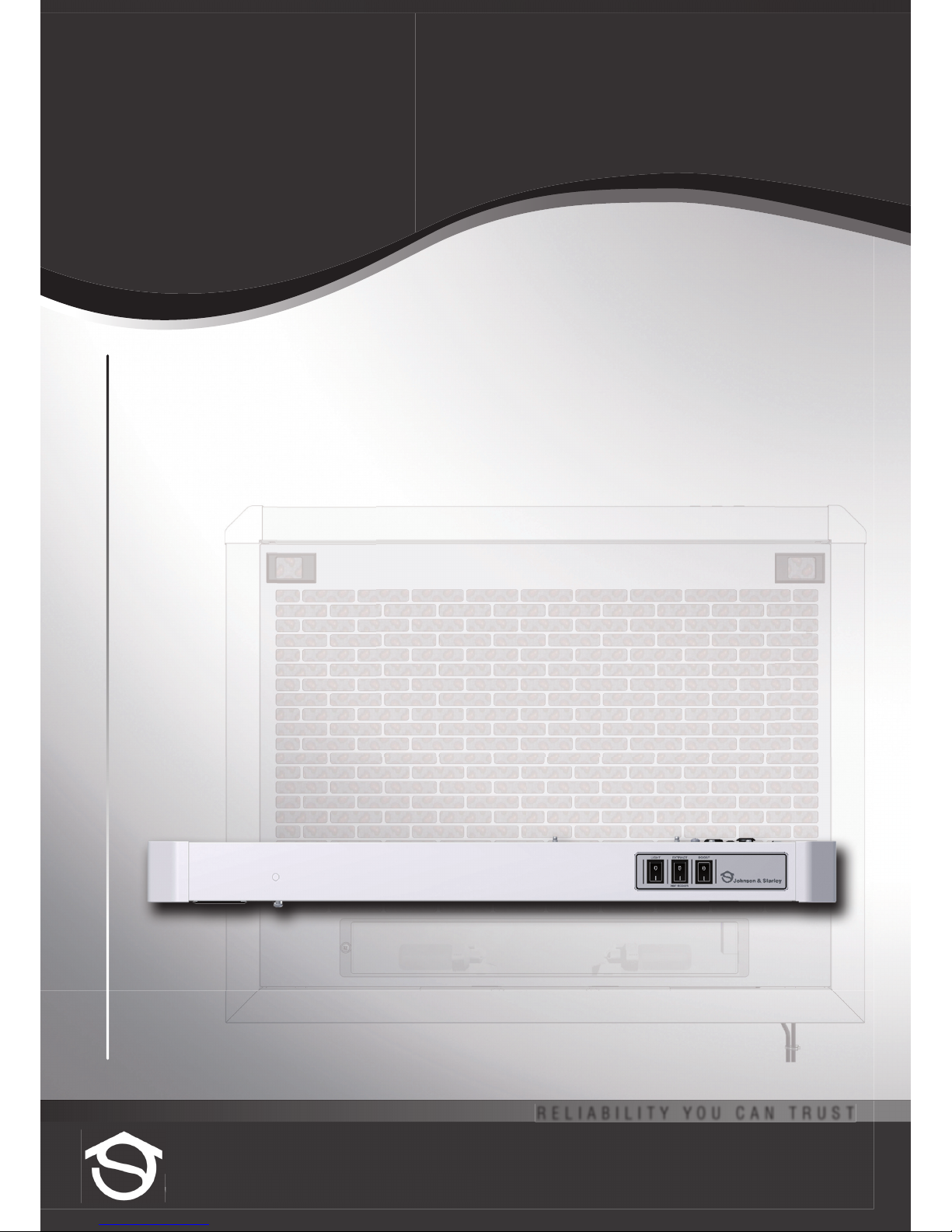
CHW & CHS
SLIM LINE COOKER HOOD
for use with HEAT RECOVERY UNITS
Installation &
Users Instructions
Page 2
1. GENERAL DESCRIPTION
1.1 The Slim Line Cooker Hood is part of a whole house mechanical
ventilation system with heat recovery. You should read these
instructions in conjunction with the instructions provided with the
LE155 heat recovery unit.
1.2 HOW IT WORKS
Warm, humid, stale air from the kitchen is drawn through the cooker
hood by the exhaust fan of the heat recovery unit, before being
discharged to the outside.
IMPORTANT
1.3 Care must be taken to avoid the dangers of flue gases from fuel
burning appliances being drawn into the living area.
1.4 If the cooker hood is fitted in a room containing a fuel burning
appliance, such as a central heating boiler, then:
a. the flue of the fuel burning appliance must be either of the room
sealed, or balanced flue type, or
b. allowances must be made for an adequate supply of air
into the room.
1.5 The exhaust from the cooker hood must be connected to the
heat recovery system and not discharged into any other flue that is
being used for the exhaust of any fumes from fuel burning appliances.
1.6 The requirement of all Building Regulation and local authorities
concerned with the discharge of exhaust air must be observed.
2. INSTALLATION
2.1 This kit must be installed by a competent person. All
electrical wiring must be installed by a suitably qualified
person and conform with I.E.E. Regulations (current edition.).
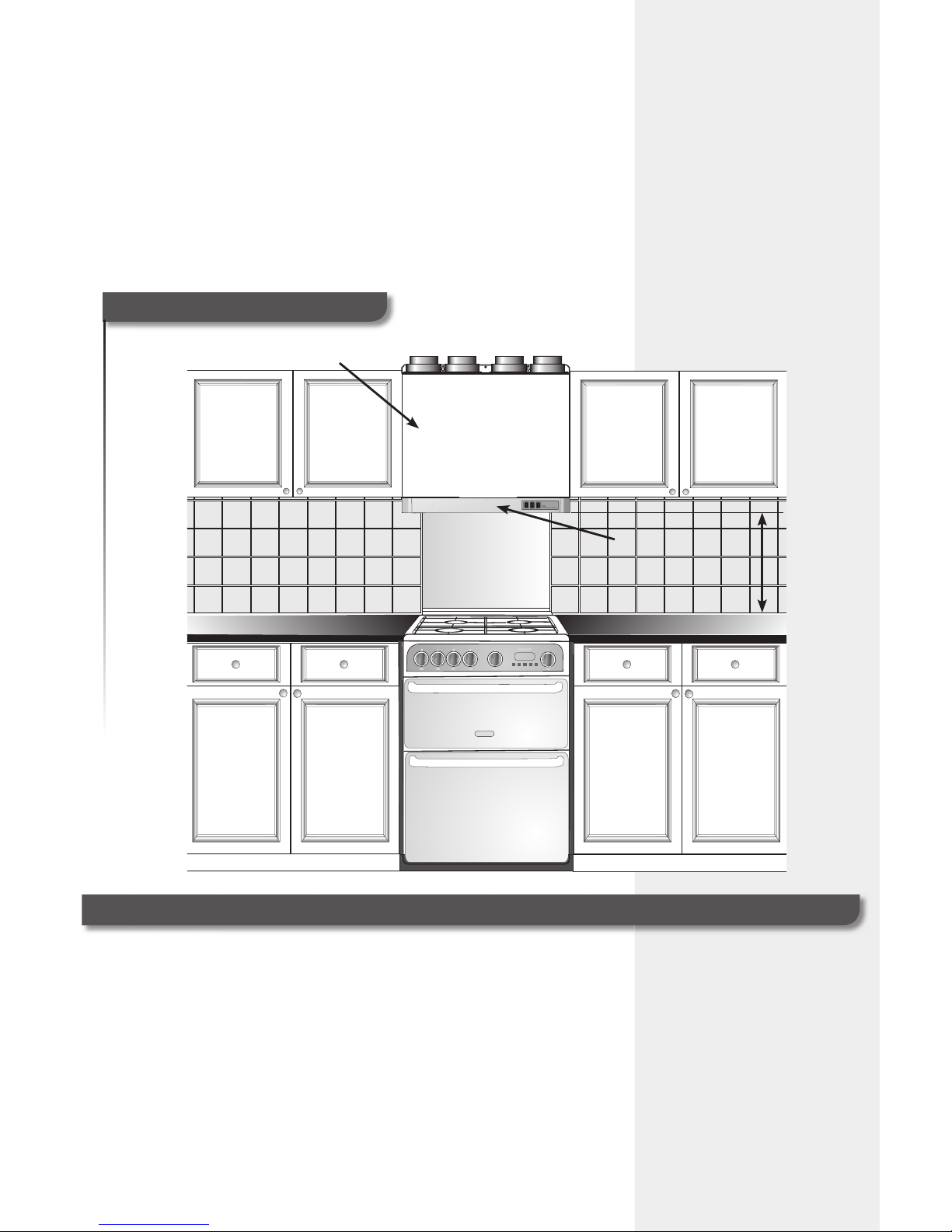
2.2 The installation height is subject to local regulations, but MUST NOT BE
LESS THAN 600mm from the top of an electric cooker, or 700mm from
the top of a gas cooker.
2.3 A fused spur box, or double pole switch having a minimum contact
separation of 3mm, must be fitted for isolation of the unit.
2.4 INSTALLATION WITH A REMOTELY FITTED LE155 HEAT
RECOVERY UNIT
2.4.1 Remove the grille from the cooker hood allowing access to the
screw positions on the inside of the unit.
2.4.1 Determine the location and height of the cooker hood and
mark off the 4 fixing hole positions using the canopy as a
template.
2.4.2 Drill the 4 x 7.5mm holes and secure
the canopy in the required position
with the screws provided.
2.4.3 For surfaces other than masonry: a
purpose made fixing is to be used.
2.5 Connect the extract duct over the fire
damper and spigot and secure into
position.
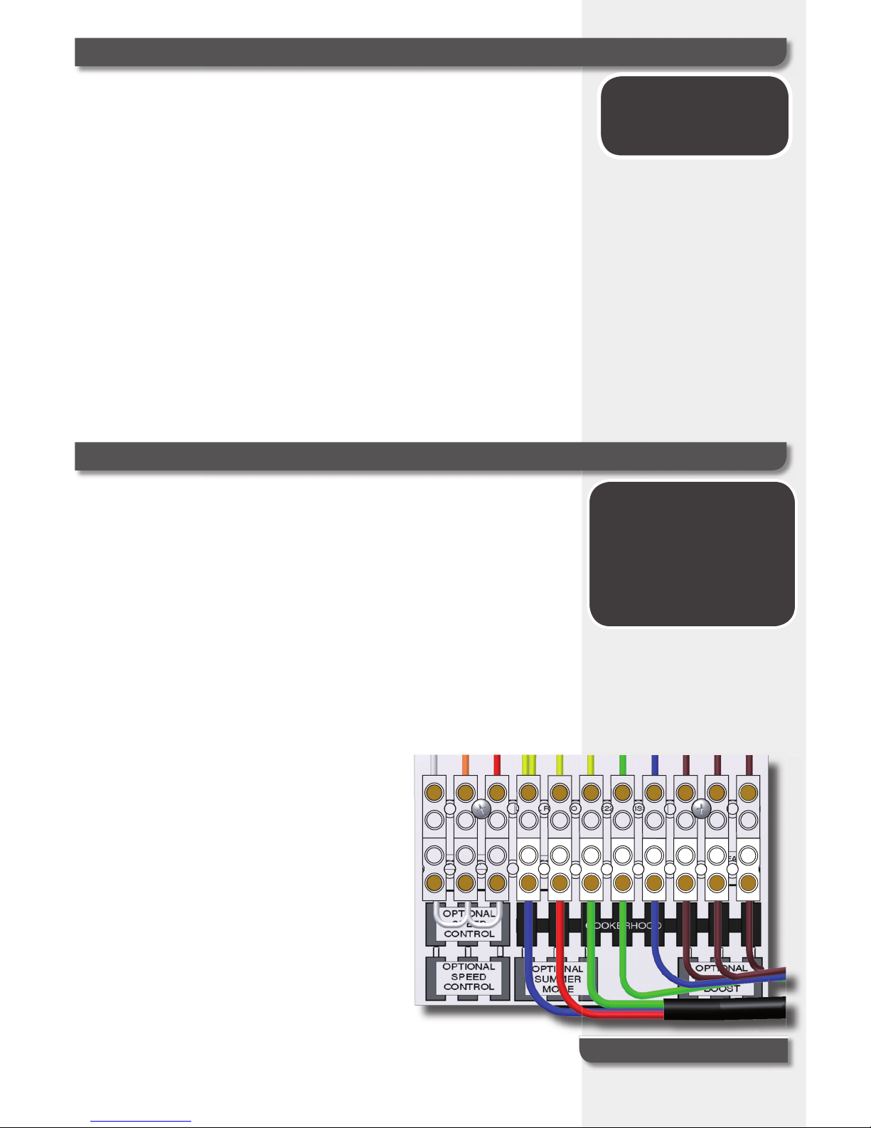
2.6 Connect the pre-wired electrical cable
to the fused spur or double pole switch,
which is to be fused at 3A.
2.7 Reconnect the grille to the cooker hood
and close.
WARNING
Do not flambé whilst
using this appliance!
IMPORTANT
INFORMATION
WARNING - THIS APPLIANCE
MUST BE EARTHED!
BEFORE STARTING THIS
PROCEDURE, YOU MUST
ENSURE THE POWER SUPPLY
TO THE UNIT HAS BEEN
SWITCHED OFF!
www.johnsonandstarley.co.uk
2
FIGURE 1
Electrical Connection
Page 3
2.8 INSTALLATION WITH AN INTEGRAL LE155 HEAT
RECOVERY UNIT
NOTE: Refer to the Installation, Commissioning and Servicing
Instructions provided with the heat recovery unit and fit in the
predetermined position above the cooker. DO NOT FIT the base plate to
the heat recovery unit. This item is to be discarded!
2.8.1 Remove the grille from the cooker hood allowing access to the
screw positions on the inside of the unit.
2.8.2 Using the screw positions where the base was fitted, fix the
cooker hood.
2.8.3 Connect the cooker hood to the heat recovery unit in accordance
with the heat recovery unit instructions.
2.8.4 Reconnect the grille to the cooker hood and close.
3. COMMISSIONING
3.1 Switch on the electrical supply to the unit.
3.2 Switch on the heat recovery unit and ensure that air is being drawn
through the cooker hood. (Measure airflow at the damper position with
the grille removed.)
3.3 Switch the lamp ON, to ensure that both lamps illuminate.
3
Telephone: 01604 762881
HR Unit Integral
with Cooker Hood
Slim Line
Cooker Hood
H
FIGURE 2
Cooker Hood Positioning
Page 4
4 USERS INSTRUCTIONS
4.1 The cooker canopy will not extract unless the heat
recovery unit is operating.
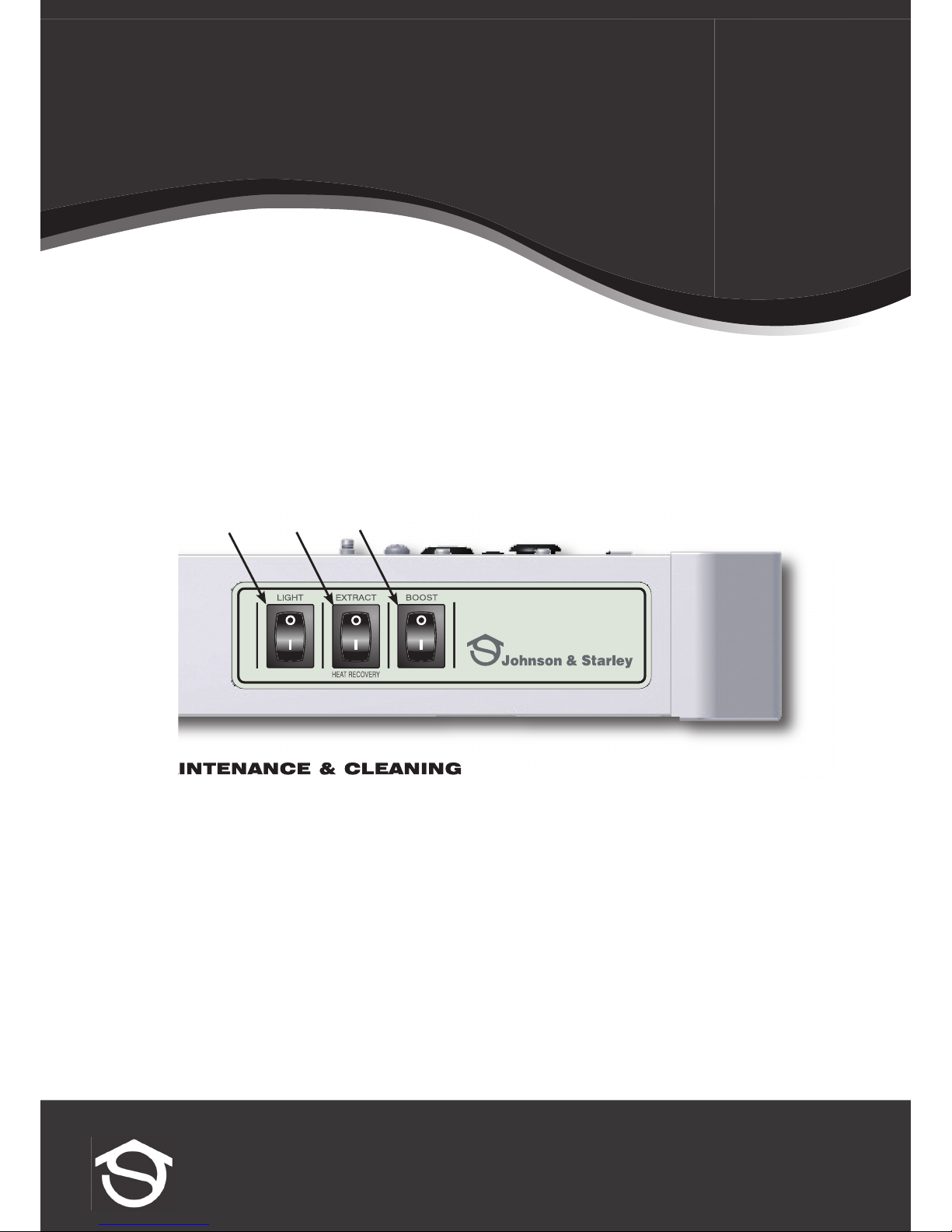
4.2 SWITCH 1
ON position - Lamp ON
4.3 SWITCH 2
OFF position - Extract Only
ON position - Heat Recovery ON
4.4 SWITCH 3
On position - Boost for maximum power
5. MAINTENANCE & CLEANING
5.1 WARNING: Cleaning instructions must be followed to prevent danger of fire! Switch OFF at
mains before starting.
5.2 Cleaning of the cooker hood and inspection of the filter must be carried out at least once per month,
but ideally on a weekly basis. Contamination of the filter will depend upon the amount and type of
cooking, but it is recommended that the filter be changed approximately every 4 months, or when
heavily contaminated.
5.3 To replace the filter, slide the two latches inward and lower the grille. Remove filter and replace with
new.
5.3 Replacement filters can be ordered using Johnson & Starley Part No. S00981.
6. LAMP REPLACEMENT
IMPORTANT: The maximum wattage for each lamp is 40W.
6.1 Isolate the power supply to the cooker canopy
6.2 Unscrew the lamps to remove them from their holders and fit new lamps.
6.3 Replacement lamps can be ordered using Johnson & Starley Part No. S00980
Johnson & Starley
Rhosili Road, Brackmills, Northampton NN4 7LZ
Main Switchboard Tel: 01604 762881 Fax: 01604 767408
Spares Tel: 01604 707012 Fax: 01604 764879
Service Tel: 01604 707011 Fax: 01604 707017
www.johnsonandstarley.co.uk
12 3
 Loading...