

Page 1

A.0500.301.A-C – IM-TW/10.00 BU/GB (0401)
A-C – General, Technical,
Disassembly & Assembly
TopWing
Rotary Lobe Pumps
Page 2
EC-Declaration of conformity
(as per EC's Machinery Directive 98/37/EC, Annex 2A)
Producer
Johnson Pump AB
P.O. Box 1436
SE-701 14 Örebro, Sweden
We hereby guarantee that:
TopWing lobe rotor pumps :
type: TW1/0041
TW1/0082
TW2/0171
TW2/0343
TW3/0537
TW3/1100
TW4/1629
TW4/3257
are in conformity with EC's Machinery Directive 98/37/EC, Annex I.
Manufacturer Declaration
(as per EC's Machinery Directive 98/37/EC, Annex 2B)
The product must not be put into service until the machinery into
which it is to be incorporated has been declared in conformity with
the provisions of the Directive.
Örebro, Sweden, 1 January 2004
Anders Larsson
Managing Director of Johnson Pump AB
Page 3

1
A.0500.301/314.A – IM-TW/10.00 GB (0401)
Contents
1.0 Introduction .......................................................................................3
1.1 General ...................................................................................................................3
1.2 Receipt, storage and handling..............................................................................3
1.2.1 Receipt, storage.......................................................................................................3
1.2.2 Handling...................................................................................................................3
1.3 Safety instructions .................................................................................................4
1.3.1 General.....................................................................................................................4
1.3.2 Pump units ............................................................................................................... 6
1.3.2.1 Pump unit handling................................................................................................ 6
1.3.2.2 Installation ..............................................................................................................6
1.3.2.3 Before commissioning the pump unit.................................................................. 7
1.3.2.4 Disassembly/assembly of the coupling guard .....................................................7
1.3.2.5 Name plate – CE Declaration of Conformity.....................................................7
1.4 Pump designation ..................................................................................................8
1.5 Pump model and serial number .........................................................................10
1.6 Pump standard parts............................................................................................10
1.7 General performance ..........................................................................................11
2.0 Function, construction, installation...............................................12
2.1 Operating principle .............................................................................................12
2.2 Operating parameters .........................................................................................12
2.3 System design and installation ...........................................................................13
2.3.1 Installations with CIP-systems, Cleaning In Place ............................................ 15
2.3.2 Installations with SIP-systems, Sterilising In Place...........................................15
2.4 Start .......................................................................................................................15
2.5 Shutdown..............................................................................................................16
2.6 Routine maintenance ..........................................................................................16
2.7 Trouble shooting chart ........................................................................................17
2.8 Heating and cooling jackets ...............................................................................18
3.0 Technical data..................................................................................19
3.1 Rotor clearances for 150°C ................................................................................19
3.2 Oil volume in gearboxes .....................................................................................20
3.3 Material specification..........................................................................................21
1.4.1 Machined parts – Pump........................................................................................21
3.4 Dimensional drawings and weights ...................................................................22
3.4.1 Standard ................................................................................................................. 22
3.4.2 Vertical mounting.................................................................................................. 23
3.4.3 Flanges....................................................................................................................24
3.4.3.1 Standard pump .....................................................................................................24
3.4.3.2 Enlarged inlet .......................................................................................................24
3.4.4 Thread and clamp connections............................................................................25
3.4.5 DIN and ANSI flanges ........................................................................................ 27
3.5 Weights..................................................................................................................28
1.6.1 Weights standard pump ........................................................................................ 28
3.6 Sound level ...........................................................................................................29
A.0500.301/314.A-C – IM-TW/10.00 GB (0401)
Page 4

2 A.0500.301/314.A – IM-TW/10.00 GB (0401)
4.0 Disassembly and assembly instructions........................................30
4.1 Tools to be used ...................................................................................................30
4.2 General instructions ............................................................................................31
4.3 O-rings and lip seals ............................................................................................31
4.4 Shutdown..............................................................................................................31
4.5 Tightening torque [Nm] for nuts and screws....................................................32
4.6 Disassembly..........................................................................................................33
4.6.1 Pump cover and rotor removal............................................................................ 33
4.6.2 Disassembly of seals.............................................................................................. 34
4.6.2.1 Single mechanical seal .........................................................................................34
4.6.2.2 Single mechanical seal with flushing.................................................................. 35
4.6.2.3 Double mechanical seal.......................................................................................35
4.6.2.4 Single O-ring seal .................................................................................................36
4.6.2.5 Double O-ring seal...............................................................................................36
4.6.3 Disassembly of drive assembly ............................................................................ 37
4.6.4 Disassembly of shaft arrangement ...................................................................... 38
4.6.5 Disassembly of rotor case..................................................................................... 39
4.7 Assembly ..............................................................................................................39
4.7.1 Pre-assembly of the rotor case............................................................................. 39
4.7.1.1 Foot assembly.......................................................................................................39
4.7.1.2 Assembly of lip seals............................................................................................39
4.7.2 Pre-assembly of shaft/bearing arrangement....................................................... 39
4.7.3 Assembly of shafts in the rotor case and setting of
the tapered roller bearings ................................................................................... 41
4.7.4 Axial adjustment of the rotors............................................................................. 42
4.7.5 Assembly of gears ................................................................................................. 43
4.7.6 Synchronization of the rotors .............................................................................. 44
4.7.6.1 Manual synchronization ......................................................................................44
4.7.6.2 Synchronization with special tools.....................................................................44
4.7.7 Assembly of end cover ......................................................................................... 45
4.7.8 Assembly of seals .................................................................................................. 46
4.7.8.1 Single mechanical seal .........................................................................................46
4.7.8.2 Single mechanical seal with flushing.................................................................. 47
4.7.8.3 Double mechanical seal.......................................................................................48
4.7.8.4 Single O-ring seal .................................................................................................49
4.7.8.5 Double O-ring seal...............................................................................................49
4.7.9 Assembly of rotors and pump cover ...................................................................50
4.7.9.1 Assembly of rotors............................................................................................... 50
4.7.9.2 Assembly of pump cover.................................................................................... 50
5.0 Special tools .....................................................................................51
5.1 General .................................................................................................................51
5.2 Assembly tool for lip seals..................................................................................52
5.3 Assembly sleeve for lip seals..............................................................................52
5.4 Assembly tool for lip seal ...................................................................................53
5.5 Assembly tool for V-seal.....................................................................................53
5.6 Tool kit for synchronization of the pump shafts ..............................................54
5.7 Tool for disassembly O-ring seal TW1..............................................................54
A.0500.301/314.A-C – IM-TW/10.00 GB (0401)
Page 5
3
A.0500.301/314.A – IM-TW/10.00 GB (0401)
1.0 Introduction
1.1 General
The range of TopWing rotary lobe pumps are manufactured by Johnson Pump, Sweden,
and are sold and marketed by a network of authorized distributors.
This instruction manual contains necessary information of the TopWing pumps and must
be read carefully before installation, service and maintenance. The manual must be kept
easily accessible by the operator.
Important!
If it is proposed to modify the system/duty or to use the pump for transporting liquids
with other characteristics than for which the pump was originally selected always consult
your distributor.
For additional information regarding the TopWing pumps, please contact your Johnson
Pump distributor.
1.2 Receipt, storage and handling
1.2.1 Receipt, storage
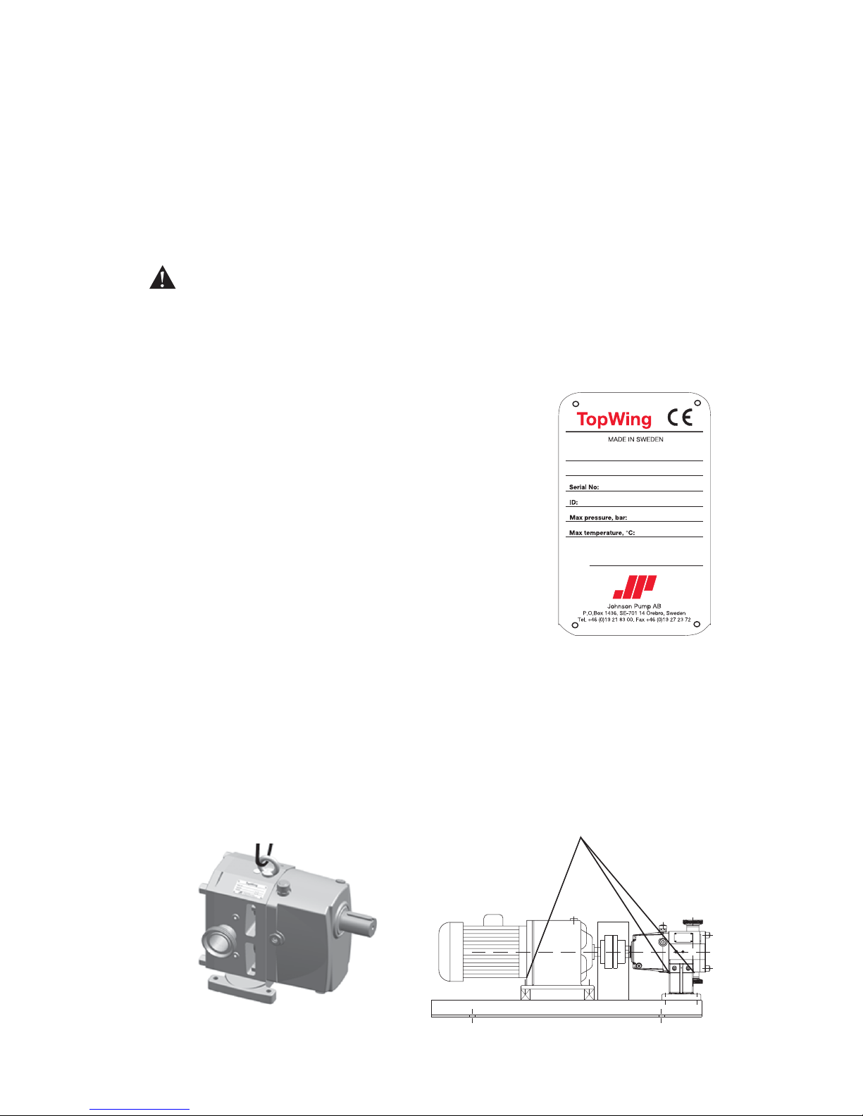
Check the consignement for damage immediately on
arrival. In case of damage, clearly mark upon the carrier’s
paperwork (with a brief description of the damage) that the
goods have been received in a damaged condition. Notify
your Johnson Pump distributor.
Always state the pump model and serial number when
asking for assistance. This information can be obtained
from the name plate which is located on the end cover (see
section 1.5).
Should the name plate be unreadable or missing, the serial
number is also stamped on the end cover and the rotor case
(see section 1.5).
If the pump is not installed immediately, it must be stored
in a suitable environment.
1.2.2 Handling
Caution must be taken when lifting the pump. All parts with a weight of more than 20 kg
must be lifted using lifting slings and suitable lifting devices.
Lifting eye fitted to pump must only be used to lift the pump, not the pump with drive
and/or baseplate.
If the pump is baseplate mounted, the baseplate must be used for all lifting purposes.
When using slings, they must be safely and securely attached (1.3 Safety instructions).
Name plate
Page 6
4 A.0500.301/314.A – IM-TW/10.00 GB (0401)
1.3 Safety instructions
1.3.1 General
This information must be read carefully before installation, operation or servicing and
always readibly be available to the pump operator.
Instructions which can affect personal safety if not followed, are marked with this
symbol
Instructions to be considered for safe operations or to protect the pump/pump unit are
marked with this symbol
When ATEX pump/pump unit is supplied, the separate ATEX manual must be
considered
• Incorrect installation, operation or maintenance of the equipment can cause serious
personal injury and/or damage to the equipment and will invalidate the warrenty.
• Never operate the pump if the pump cover or suction and discharge pipework are
not in place. Likewise, never operate the pump if other protection such as coupling
and touch guards are missing or incorrectly fitted.
• Never stick your fingers inside the rotor case, connections to the casing or in the end
cover if there is any possibility that the pump shafts may rotate. This can lead to
serious personal injury.
• Do not exceed the pump’s maximum operating pressure, speed or temperature. Do
not modify the operating parameters/system for which the pump was orginally
delivered without first consulting Johnson Pump.
• Pump installation and operation must always comply with prevailing health and
safety regulations.
• Some sort of safety equipment should be connected to the pump, system or the drive
to prevent the pump from exceeding maximum allowable pressure. The safeguard
system must be configured to handle reverse flow where applicable.
Do not operate the pump with a closed/blocked discharge unless a safety relief valve
is incorporated. If an integrated safety relief valve is incorporated into the pump, do
not allow extended periods of recirculation through the relief valve.
• The installation of the pump/pump unit must be sturdy and stabile. Pump orientation
must be considered with respect to drainage requirements. Once mounted, check the
alignment between the pump and the drive assembly. Misalignment of the pump,
drive and shaft coupling will result in unnecessary wear, increased operating temperatures and noisier operation.
• Fill the pump’s and drive’s end cover with the recommended lubricants and
amounts. Change the lubricants at the recommended intervals.
• Before operating the pump, make sure that it and the pipe system are clean and free
from debris and that all the valves in the suction and discharge pipelines are fully
opened. Make sure that all pipework connected to the pump is fully supported and
correctly aligned. Misalignment and/or excessive loads will cause severe damage to
the pump.
• Make sure that the pump rotation is correct for the desired flow direction.
• Do not install the pump into a system where it may run dry (i.e. without a supply of
pumped media) unless it is equipped with a flushed shaft seal arrangement, complete
with a fully operational flushing system.
• Install pressure gauges/sensors in conjuction with the pump’s suction and discharge
connections to monitor the pump’s pressure.
Page 7
5
A.0500.301/314.A – IM-TW/10.00 GB (0401)
• Caution must be taken when lifting the pump, appropriate lifting devices should be
used if possible. Lifting rings fitted to the pump are only to be used for lifting the
pump, not for lifting the pump with drive and/or baseplate. For baseplate mounted
pumps the baseplate is to be used for all lifting purposes. If slings are used for lifting,
they must be safely and securely attached.
• Do not attempt maintenance work or disassembly of the pump or pump unit without
making sure that the power switch to the drive unit (electric, hydraulic or pneumatic)
is locked and cannot be switched on. Depressurize and purge any pressure relief
valve and/or shaft seal flushing system. Check that any other associated equipment is
turned off and disconnected. Allow the pump and components to cool down to a safe
handling temperature.
• Do not attempt to dismantle a safety/pressure relief valve whose spring pressure has
not been relieved, is connected to a pressurized gas/air supply or mounted on a
pump in operation. Serious personal injury and/or damage to the pump may occur.
• Do not attempt to loosen or remove the pump cover, connections to the pump, shaft
seal housings, pressure/temperature control devices or other components until you
are sure that such actions will not lead to the unsafe escape of any pressurized media.
• The pump installation must allow for safe routine maintenance and inspection
(check for leakage, change of lubricants, pressure monitoring, etc) and provide
adequate ventilation to prevent overheating.
• Pumps and/or drive units can produce sound levels in excess of 85dB(A) under
unfavorable operating conditions. When necessary, personal protection against noise
must be used. See the curves for sound levels in “Section 3.6’’.
• Avoid any contact with hot parts of the pumps or drive units which may cause
personal injury. If the surface temperature of the system exceeds 60°C, the system
must be marked with a warning sign of “hot surface”. Operating conditions with
temperature control devices (jacketed, electrically heated, etc), bad installation or
poor maintenance can promote unnormally high temperatures on pumps and/or
drive units.
• When cleaning, either manually or by CIP method, the operator must ensure that a
suitable procedure is used in accordance with the system requirements. During a CIP
cleaning cycle, a pump differential pressure of between 2 and 3 bar is recommended
to ensure that suitable velocities are reached in the pump head. The exterior of the
pumps should be cleaned periodically.
Pumps must always be installed and operated in compliance with prevailing national and
local health and safety regulations and legislation. The pump must be completely
isolated from the pipe work and drive motor before any maintenance work is to be
undertaken. In the event of hazardous products the system, as well as the pump, must be
drained. Never operate the pump without the pump cover.
Always follow all applicable safety measures when manually cleaning the pump:
• Drive unit must be shut down so that it cannot be started.
• Any compressed air controlled, mounted safety relief valve must be closed and
depressurized.
• Connections to flushed mechanical seals must be closed and depressurized.
• The pump and pipe work must be drained and depressurized.
Equipment that is incorrectly installed, operated in a dangerous manner or is poorly
maintained poses a potential safety hazard. If all reasonable safety measures are not
followed, serious personal injury and material damage may occur.
Page 8
6 A.0500.301/314.A – IM-TW/10.00 GB (0401)
1.3.2 Pump units
1.3.2.1 Pump unit handling
Use an overhead crane, forklift or other suitable lifting device.
1.3.2.2 Installation
All pump units should be equipped with a locking safety switch to prevent accidental
start during installation, maintenance or other work on the unit.
Warning
The safety switch must be turned to off and locked before any work is carried out on the
pump unit. Accidental start can cause serious personal injury.
The pump unit must be mounted on a level surface and either be bolted to the
foundation or be fitted with rubber-clad feet.
The pipe connections to the pump must be stress-free mounted, securely fastened to the
pump and well supported. Incorrectly fitted pipe can damage the pump and the system.
Warning
Electric motors must be installed by authorized personnel in accordance with EN60204-1.
Faulty electrical installation can cause the pump unit and system to be electrified, which
can lead to fatal injuries.
Electric motors must be supplied with adequate cooling ventilation. Electric motors must
not be enclosed in airtight cabinets, hoods etc.
Dust, liquids and gases which can cause overheating and fire must be diverted away from
the motor.
Warning
Pump units to be installed in potentially explosive environments must be fitted with an Exclass (explosion safe) motor. Sparks caused by static electricity can give shocks and ignite
explosions. Make sure that the pump and system are properly grounded. Check with the
proper authorities for the existing regulations. A faulty installation can lead to fatal
injuries.
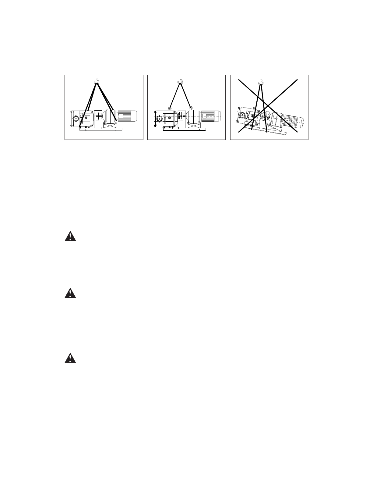
Secure lifting slings around the
front part of the pump and the
back part of the motor. Make
sure that the load is balanced
before attempting the lift.
NB! Always use two lifting
slings.
If there are lifting rings on
both the pump and the motor
the slings may be fastened to
these.
NB! Always use two lifting
slings.
Warning
Never lift the pump unit with
only one fastening point.
Incorrect lifts can result in
personal injury and/or damage
to the unit.
Page 9
7
A.0500.301/314.A – IM-TW/10.00 GB (0401)
1.3.2.3 Before commissioning the pump unit
Read the pump’s operating and safety manual. Make sure that the installation has been
correctly carried out according to the relevant pump’s manual.
Check the alignment of the pump and motor shafts. The alignment may have been
altered during transport, lifting and mounting of the pump unit. For safe disassembly of
the coupling guard see below: Disassembly/assembly of the coupling guard.
Warning
The pump unit must not be used with other liquids than those for which it was
recommended and sold. If there are any uncertainties contact your Johnson Pump sales
representative. Liquids, for which the pump is not appropriate, can damage the pump and
other parts of the unit as well as cause personal injury.
1.3.2.4 Disassembly/assembly of the coupling guard
The coupling guard is a fixed guard to protect the users and operator from fastening and
injuring themselves on the rotating shaft/shaft coupling. The pump unit is supplied with
factory mounted guards with certified maximum gaps in accordance with standard
EN 294:1992.
Warning
The coupling guard must never be removed during operation. The locking safety switch
must be turned to off and locked. The coupling guard must always be reassembled after it
has been removed. Make sure to also reassemble any extra protective covers. There is a
risk of personal injury if the coupling guard is incorrectly mounted.
a) Turn off and lock the power switch.
b) Disassemble the coupling guard.
c) Complete the work.
d) Reassemble the coupling guard and any other protective covers. Make sure that the
screws are properly tightened.
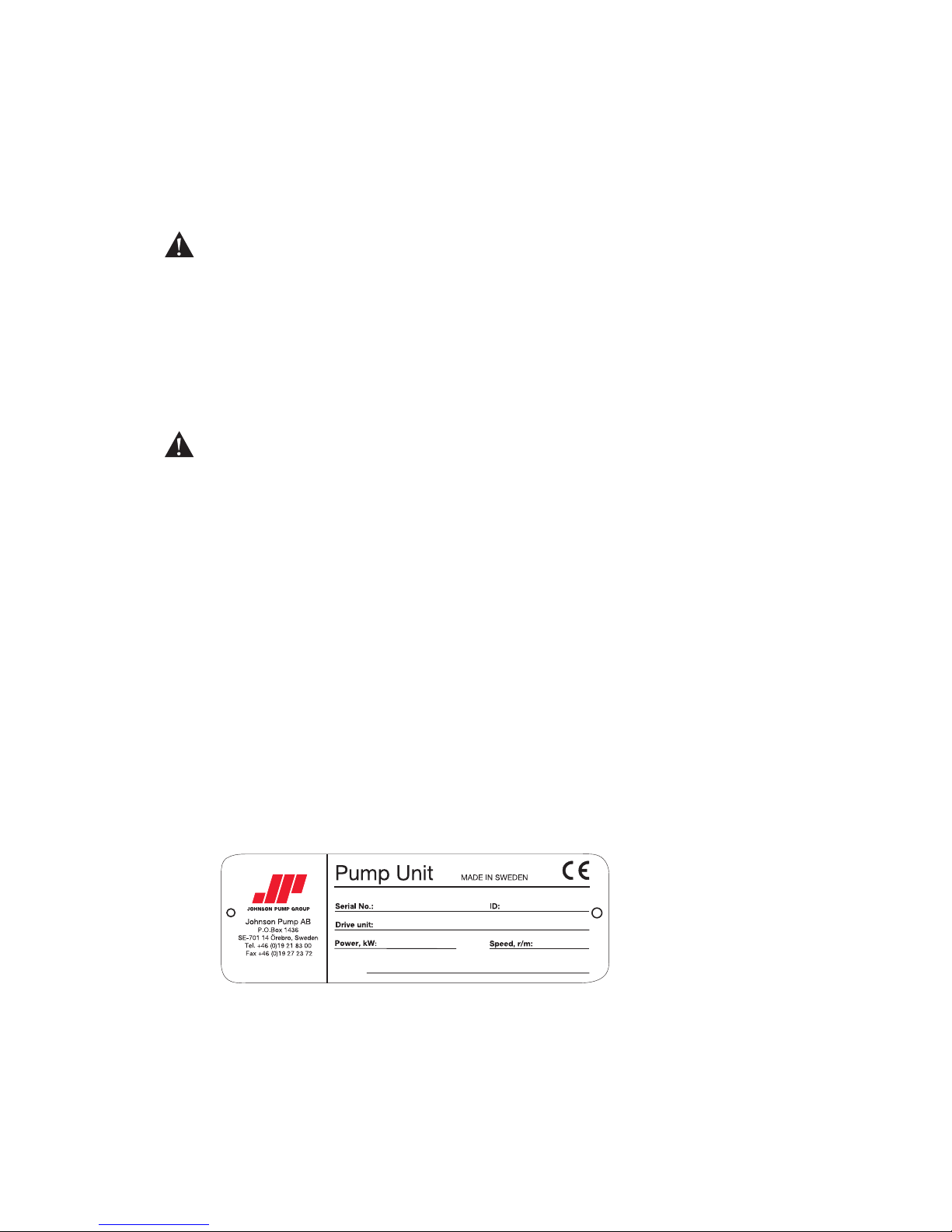
1.3.2.5 Name plate – CE Declaration of Conformity
Always quote the serial number on the name plate together with questions concerning
the pump unit, installation, maintenance etc.
When changing the operating conditions of the pump please contact your Johnson Pump
distributor to ensure a safe and reliable working pump.
This also applies to modifications on a larger scale, such as a change of motor or pump
on an existing pump unit.
Page 10

8 A.0500.301/314.A – IM-TW/10.00 GB (0401)
1.4 Pump designation
Example:
1. Pump family name
TW = TopWing
2. Size of drive assembly
1, 2, 3, 4
3/4. Hydraulics indicated with displacement volume per revolution and
connection diameter
Displacement Inlet diameter
volume per revolution (in dm
3
) Standard pump Enlarged inlet
TW1/0041 0.041 25 25/40
TW1/0082 0.082 25 25/40
TW2/0171 0.171 40 40/50
TW2/0343 0.343 50 50/80
TW3/0537 0.537 50 50/80
TW3/1100 1.100 80 80/100
TW4/1629 1.629 80 80/100
TW4/3257 3.257 100 100/150
5. Connection type
01 Hygienic threaded connection to DIN 11851/DIN 405
02 PN16 flanges to DIN 2633
04 Threaded connection to ISO 2853
05 Threaded connection for dairy industry BS 4825
06 SMS 1145 threaded connections
07 Clamp to ISO 2852
08 Flanges to ANSI B16,5 – 150 lbs
10 Gas thread ISO 7/1
11 DS 722 thread
12 Clamp to SMS 3017 (Triclamp)
13 NPT thread to ASA B2.1
14 Clamp to DIN 32676
6. Rotor
W1 Wing rotor in stainless steel medium clearances
TW 2/ 0171- 40/ 06- W1 1- GB2 1- V V S
1 2 3 4 5 6 7 8 9 10 11 12
Page 11

9
A.0500.301/314.A – IM-TW/10.00 GB (0401)
Example:
7. Pump covers
1 Cover
2 Cover with safety relief valve spring loaded
3 Cover with safety relief valve spring loaded and air lifted
4 Cover with safety relief valve air loaded and air lifted
5 Cover with jacket
6 Cover with safety relief valve spring loaded and with jacket
7 Cover with safety relief valve spring loaded and air lifted and
with jacket
8 Cover with safety relief valve air loaded and air lifted and
with jacket
8. Seals
GW1 Single mechanical seal SiC to SiC
GB1 Single mechanical seal SiC to Carbon
GW2 Single mechanical seal SiC to SiC with flushing
GB2 Single mechanical seal SiC to Carbon with flushing
DW2 Double mechanical seal SiC to SiC to Carbon
DB2 Double mechanical seal Carbon to SiC to Carbon
O1 Single O-ring seal
DO2 Double O-ring seal with flushing
9. Feet
1 Horizontal connections – top drive
2 Horizontal connections – bottom drive
3 Vertical connections right hand drive from shaft end
4 Vertical connections left hand drive from shaft end
10. Kits for different O-ring material for hydraulic part
V Viton
E EPDM
EF EPDM - FDA
T PTFE lined O-rings
C Chemraz
K Kalrez
11. Kits for different O-ring material for seal
V Viton
E EPDM
EF EPDM - FDA
C Chemraz
K Kalrez
12. Special execution
For details please contact Johnson Pump.
Position deviating from standard marked with X.
TW 2/ 0171- 40/ 06- W1 1- GB2 1- V V S
1 2 3 4 5 6 7 8 9 10 11 12
Page 12
10 A.0500.301/314.A – IM-TW/10.00 GB (0401)
1
2
3
4
5
6
7
8
9
1
0
1
1
1
2
1
3
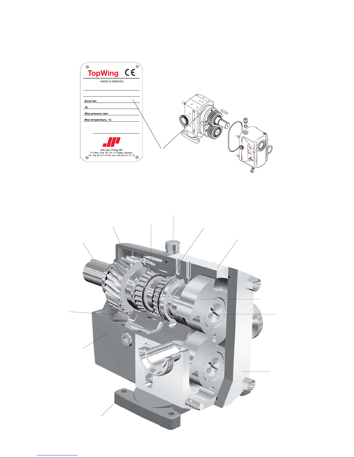
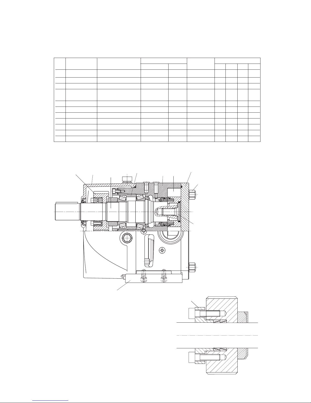
1.6 Pump standard parts
To avoid mistakes kindly always use the following terms for the different pump parts:
1.5 Pump model and serial number
If you require further information regarding the TopWing pumps, please contact your
Johnson Pump distributor quoting the pump model and
serial number. This information is stated on the name
plate which is attached to the rotor case. If the name plate
is damaged or missing, the serial number is also stamped
on the rotor case under the endcover.
Serial number
Drive shaft
Gear
drive shaft
Rotor case
Retainer
Bi-Wing rotor
Pump cover
Air breather
Foot
Gear
lay shaft
Taper roller
bearing
Taper roller
bearing
End cover
Page 13
11
A.0500.301/314.A – IM-TW/10.00 GB (0401)
TW1/0041
TW2/0171
TW3/0537
TW4/1629
TW1/0082 TW2/0343 TW3/1100 TW4/3257
20
15
10
5
0
110
100
1000
25
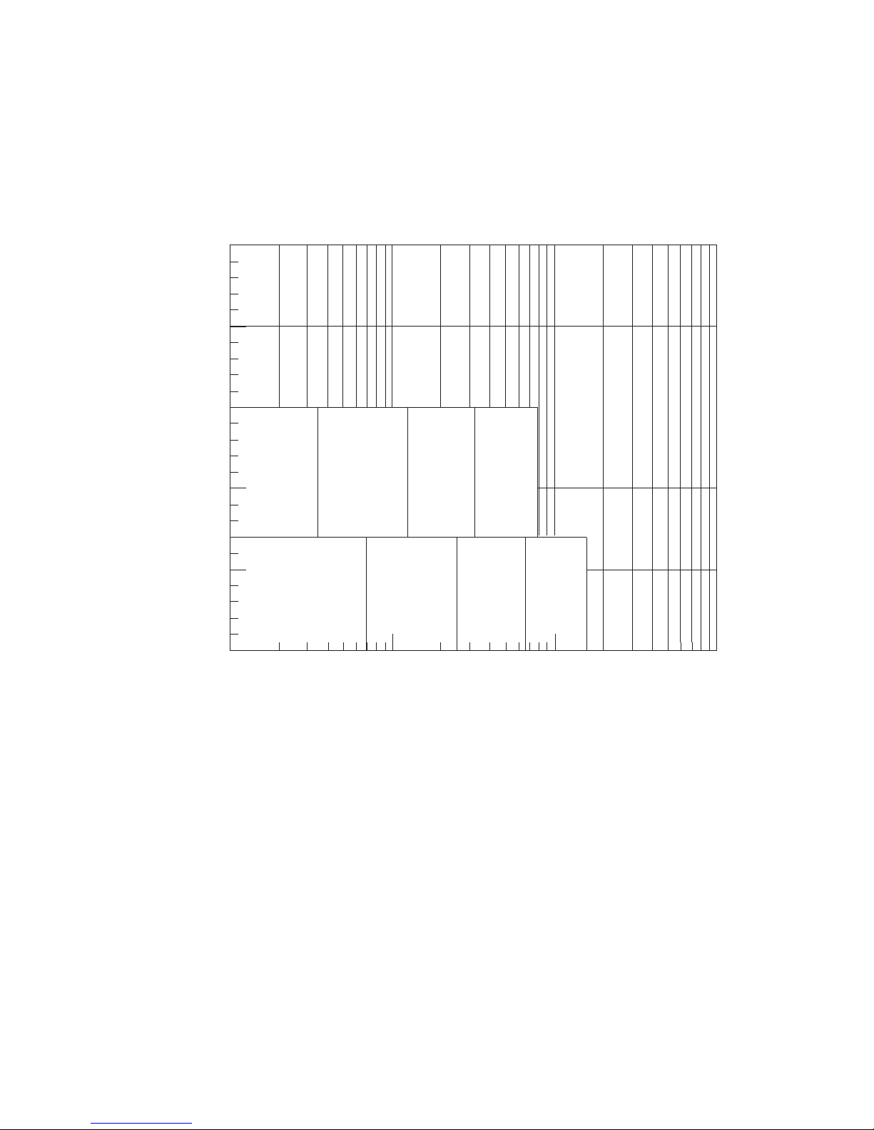
1.7 General performance
The maximum capacity and pressure of the pumps is shown in the curve below, this will
give an overview of the application field.
The curves show the extreme limits, but for many applications the limits are tighter and
therefore when changing the operating conditions of the pump please contact your
Johnson Pump distributor to ensure a safe and reliable working pump.
Differential pressure – bar
Capacity – m3/h
Page 14
12 A.0500.301/314.A – IM-TW/10.00 GB (0401)
a
bcd
e
2.0 Function, construction, installation...
2.1 Operating principle
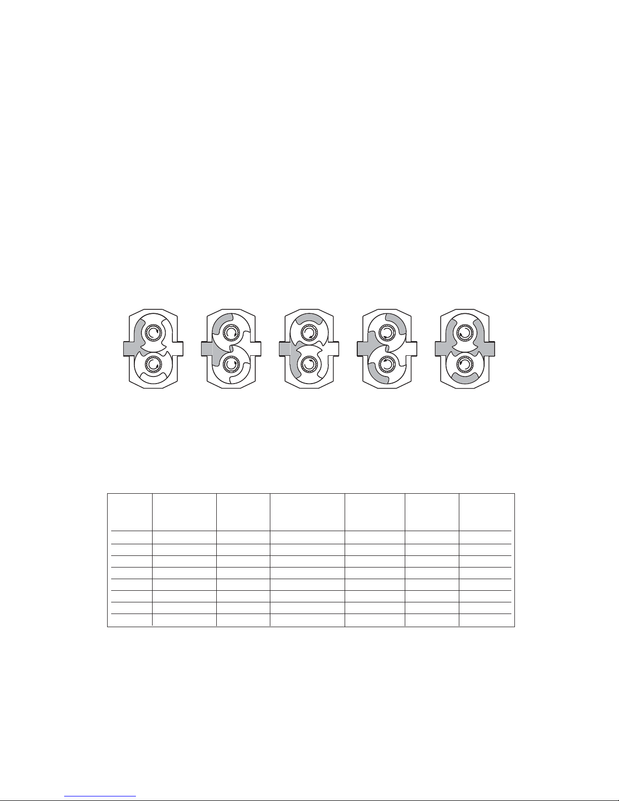
The pumping action of the TopWing is achieved by the contra rotation of two Bi-Wing
rotors within a rotor case. The rotors are mounted on shafts, which
are supported by tapered roller bearings, integrated in the rotor case. The second shaft is
driven by the drive shaft via a set of timing gears that are fixed on the shaft by means of
adjustable locking elements. The rotors are synchronized so that they rotate without
contact with each other.
As the wings of the rotors move away from each other the volume between them
increases, creating a decrease in pressure opposite the suction port (see fig. a).
This causes the media to flow into the rotor case.
The pumped media is carried around the rotor case (see fig. b and c) to the
discharge side of the pump (see fig. d). As the wings of the rotors move towards each
other, the volume between them decreases, causing a rise in pressure opposite the
discharge port. This causes the media to be pressed out of the rotor case (see fig. e).
Regarding the pump standard parts, see section 1.6.
2.2 Operating parameters
The maximum pressure and speed operating data are given in the table below. In
practice these performance data can be limited by the nature of the pumped media and/
or the design of the system in which the pump is installed.
max pump speed = n
max
swept volume = Vi
theoretical capacity at max speed and ∆p = 0 bar = Qth
max
max differential pressure = ∆p
max
max operating pressure = p
max
max torque on shaft end = T
max
theoretical capacity
at max speed max differential max operating max torque on
Pump type max pump speed swept volume and ∆p = 0 bar pressure pressure shaft end
[rpm] [dm3] [m
3
/h] [bar] [bar] [Nm]
TW1/0041 1400 0.041 3.4 15 18 55
TW1/0082 1400 0.082 6.9 7 10 55
TW2/0171 1200 0.171 12.3 15 18 400
TW2/0343 1200 0.343 24.7 7 10 400
TW3/0537 1000 0.537 32.2 15 18 800
TW3/1100 1000 1.100 66.0 7 10 800
TW4/1629 800 1.629 78.2 15 18 2000
TW4/3257 800 3.257 156.3 7 10 2000
Page 15

13
A.0500.301/314.A – IM-TW/10.00 GB (0401)
The pump is not to be exposed to rapid temperature changes to avoid damage through
sudden expansion/contraction of the pump components.
Pumps for handling abrasive liquids (causing wear) should be selected with care. Please
contact your Johnson Pump distributor for advice.
Important!
If it is proposed to modify the system/duty or to use the pump for transporting liquids
with other characteristics than for which the pump was originally selected always consult
your distributor.
2.3 System design and installation
When a pump is to be incorporated in a system, it is considered good practice to, as far
as possible, minimise the length of the pipes and the number of pipe fittings (tees,
unions, bends etc.) and the restrictions.When designing the suction lines, particular care
should be taken. These should be as short and straight as possible, using a minimum of
pipe fittings to achieve a good product flow to the pump. Always consider the following
when designing a system:
1. Ensure there is space enough around the pump to allow for:
a) Routine check and maintenance of the complete pump unit, seal area,
drive motor, etc.
b) Good ventilation for the drive to avoid overheating.
2. Both the suction and the discharge ports must be provided with valves. During
check-up procedures or maintenance work, the pump must be isolated from the
system.
3. The system design, pipes and other equipment must have independant supports to
avoid heavy loads on the pump. In the case of pipe work or other equipment relying
on the pump fixings for support, there is a big risk for serious damage to the pump.
4. For positive displacement pumps as TopWing it is recommended to install some
safeguards, for example:
a) Built-on safety relief valves
b) External pressure relief valve system for recirculation to tank or
suction side of the pump.
c) Torque device in the system, mechanical or electrical.
d) Rupture disc in the discharge pipework.
If the system can be ruined by reversed flow direction, safeguards must be considered for both directions of rotation/flow.
5. It is considered good practice to thoroughly clean all pipework and associated
equipment from the suction port to the discharge port before installation of pump.
This is to avoid the risk of debris entering the pump and causing damage.
6. If possible, pressure gauges should be placed at the suction port and the discharge
port of the pump, so that the system pressures can be monitored. These gauges give
a clear indication of changes in the operating conditions. If a relief valve is
incorporated in the system the gauges will be necessary for setting and checking the
function of the valve.
7. It is very important that the suction condition at the pump inlet meets the NPSH
required of the pump. Failure to observe this can cause cavitation, which leads to a
noisy operation, reduced flow and mechanical damage on the pump and associated
equipment.
Page 16
14 A.0500.301/314.A – IM-TW/10.00 GB (0401)
Vacuum table
Atmospheric
pressure
For conditions with
positive suction head
NPSH available
Suction lift
or vacuum
Suction line
friction loss
Vapour
pressure
NPSH available
Suction
head
Suction line
friction loss
Vapour
pressure
Absolute
vacuum
For suction lift or
vacuum conditions
≅10 m
water
column
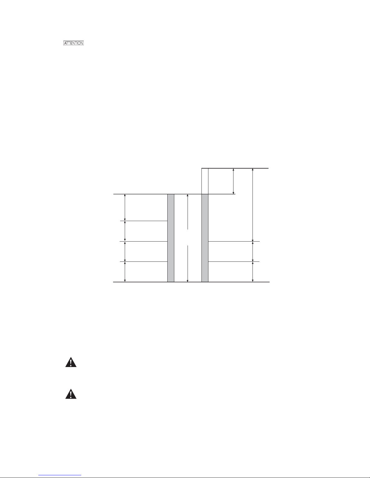
The NPSH available from the system must always exceed the NPSH required by the
pump. If the following guidelines are observed it should ensure the best possible suction
conditions.
• The suction line should have at least the same diametre as the pump connections.
• The suction line should be as short as possible.
• Use a minimum of bends, tees and pipework restrictions.
• The calculations to determine the NPSH available from the system should be carried
out for the worst condition, see vacuum table.
• If a filter is used on the suction pipe, check pressure drop at the actual flow.
This is important to avoid cavitation which can damage the pump.
Please contact your Johnson Pump distributor if you require information on the pump or
system NPSH characteristics.
8. When installing a pump complete with drive motor and baseplate the following
guidelines must be observed:
a) The most suitable drive for the TopWing pumps is to use a motor with direct
coupling. Please contact your Johnson Pump distributor if using some other
method.
b) Flexible couplings must always be used and aligned correctly within the limits
recommended by the coupling manufacturer. Turn the shaft at least one full
rotation to control the alignment of the coupling and that the shaft rotates
smoothly.
c) Couplings must always be enclosed in a suitable guard to prevent contact with
rotating parts which could cause personal injury. Such guards must be of suitable
material - see point d - and be of sufficiently rigid design to prevent contact with
the rotating parts during normal operation.
Page 17
15
A.0500.301/314.A – IM-TW/10.00 GB (0401)
d) When installing pump sets in flammable or explosive environments or for
handling flammable or explosive media, special consideration must be given not
only regarding the security of the drive unit enclosure, but also for the materials
used both in couplings and guards to eliminate the risk of explosion.
e) The base plate must be secured to a flat level surface to avoid misalignment and
distortion. When the baseplate is fastened in position, the alignment must be
checked again, see point b.
f) If the pump is driven by an electric motor, check that the motor and other
electrical equipment are compatible with the drive and that the wiring is correct,
i.e. Direct On-Line, Star Delta etc. Ensure that all components are correctly
electrically grounded.
2.3.1 Installations with CIP-systems, Cleaning In Place
The TopWing pumps are constructed so that they easily can be cleaned with CIPmethods for cleaning of processing plants. To achieve the necessary fluid velocities
within the pump when cleaning we recommend a differential pressure of 2-3 bars across
the pump.
Recommendation: A built-on safety relief valve, spring loaded-air lifted, creates the
possibility to achieve the flow in the pipe work after the pump without using separate
CIP-valves and a by-pass connection.
2.3.2 Installations with SIP-systems, Sterilising In Place
TopWing pumps are capable of handling a SIP-process.
Contact Johnson Pump for information regarding the temperatures needed for the
process, as temperature has an effect on the clearances in the pump.
Equipment components may need sterilising, i.e. heating to high temperatures
(up to 140°C) to kill organisms still remaining on the surface of the equipment. Sterilising is done by using steam or pressurised, heated water.
2.4 Start
• Make sure that all associated equipment is clean and free from debris and that all
pipe connections are secure and correctly sealed.
• For pumps fitted with flushed product seals check that all required services for
flushing purposes are in place and connected.They must give sufficient flow and
pressure for the flushing purposes. Contact Johnson Pump for advice. For seal plans,
see ’’E, F, G manuals’’ respectivley.
• Check the lubrication for the pump and drive. The TopWing pumps are delivered
without oil and should be filled to the level of the oil level glass. See “Section 3.2’’
regarding pump oil capacities and grades.
• If an external relief valve is incorporated in the system, check that it is set correctly.
It is considered good practice to set the relief valve lower than the system design
pressure. After commissioning, the relief valve should be reset to the required
setting for the application. The required setting should never exceed the lower of
either the pumps maximum pressure rating or the system design pressure.
Page 18
16 A.0500.301/314.A – IM-TW/10.00 GB (0401)
• Check that the valves are completely open on both the inlet and outlet and that the
pipelines are free from obstructions. The TopWing pumps are of the positive displacement type and should therefore never be operated against a closed valve, as
this would result in pressure overload, damages on the pump and possibly damage
on the pump system.
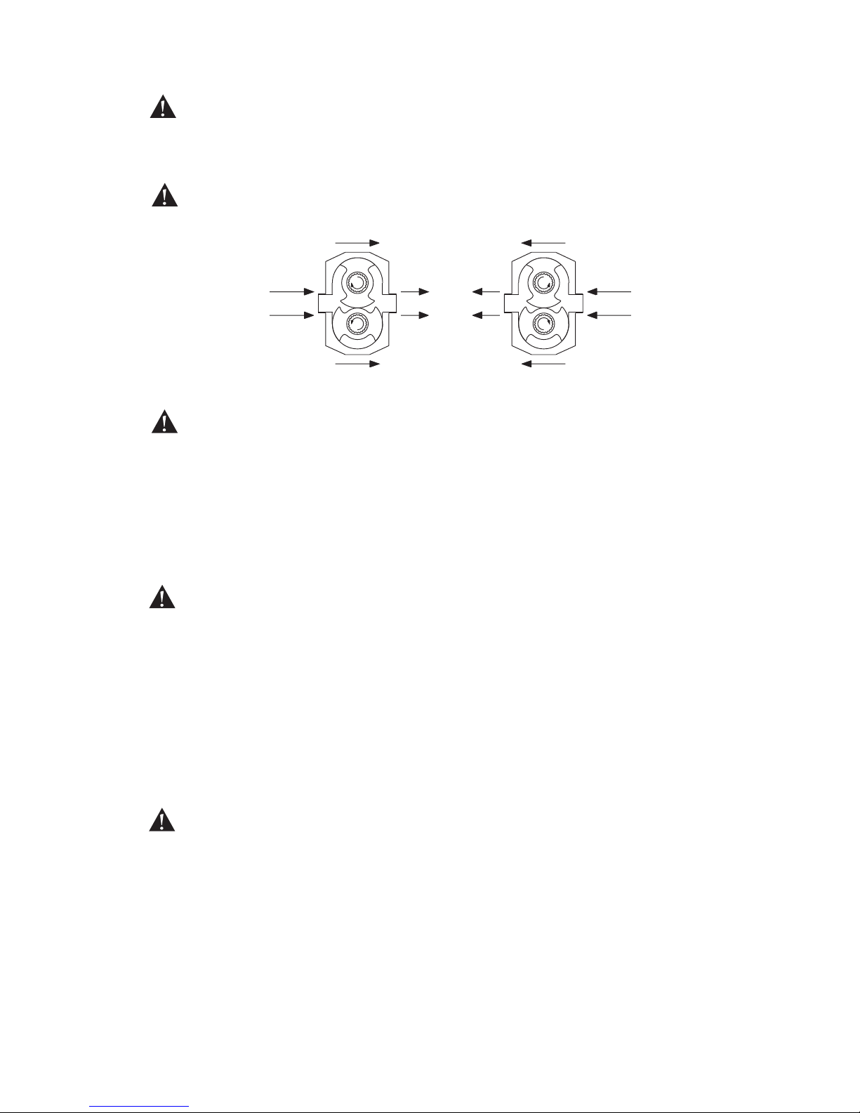
• Check that the drive shaft has the correct direction of rotation for required flow, see
figure below.
• Before starting the pump, make sure that there is liquid on the suction side.
This is very important for pumps with unflushed product seals as these sealing arrangements must never run dry.
• Before operating the pump it is considered good practice to briefly start and stop the
pump to check the direction of rotation and to make sure that there are no
obstructions what so ever for the function. When this has been done the operation
can begin. Keep a visual check on the suction and discharge pressure gauges and
monitor the pump temperature and absorbed power where possible.
2.5 Shutdown
When shutting the pump down the valves on the suction and discharge side must be
closed. Following precautions must be taken:
• The power is shut off and the starting device locked so that the pump cannot be
started.
• The pneumatic relief valve is purged.
• The connections for the flushed mechanical seals are shut off and depressurised.
• The pump and pipelines must be empty and de-pressurised.
See chapter “4.0 Disassembly and assembly instructions’’ before undertaking any work
on the pump.
2.6 Routine maintenance
• Check the oil level regularly.
• Change the oil once a year or every 3000 operating hours, whichever comes first.
• For lubricant capacities and grades, see “Section 3.2’’.
• Measure vibration and temperature, these factors can indicate bearing failure.
Direction of rotation
RotationRotation
Suction
Discharge Suction
Page 19

17
A.0500.301/314.A – IM-TW/10.00 GB (0401)
2.7 Trouble shooting chart
Symptom Causes Actions
No Irregular Low Pump Motor Exessive Exessive Noise/, Seizure Pump
flow flow capacity over- over- rotor seal Vibra- stalls on
heats heats wear wear tions start up
•
Incorrect direction of rotation Reverse motor
•
Pump not primed Expel gas from suction line/pump chamber and prime
• • • •
Insufficient NPHS available Increase suction line dia and static suction head
Simplify suction line and reduce length
•• •
Product vapourising in suction line Reduce pump speed and product temperature
•• •
Air entering suction line Remake pipework joints
• • • •
Gas in suction line Expel gas from suction line/pump chamber
•• •
Insufficient static suction head Raise product level to increase static suction head
•• • •
Product viscosity too high Decrease pump speed/increase product temperature
•
Product viscosity too low Increase pump speed/decrease product temperature
•• • • •
Product temperature too high Cool product/pumping chamber
••
Product temperature too low Heat product/pumping chamber
••••
Unexpected solids in product Clean the system/fit strainer on suction side of pump
•••• •••
Discharge pressure too high Check for blockages/simplify discharge line
•• • • •
Rotor case strained by pipework Check pipe alignment/support pipework
••
Pump speed too high Decrease pump speed
•
Pump speed too low Increase pump speed
•• • • • •
Seal flush inadequate Increase seal flush to required pressure/flow
•• • • • ••
Bearing/timing gear wear Replace worn components
Page 20
18 A.0500.301/314.A – IM-TW/10.00 GB (0401)
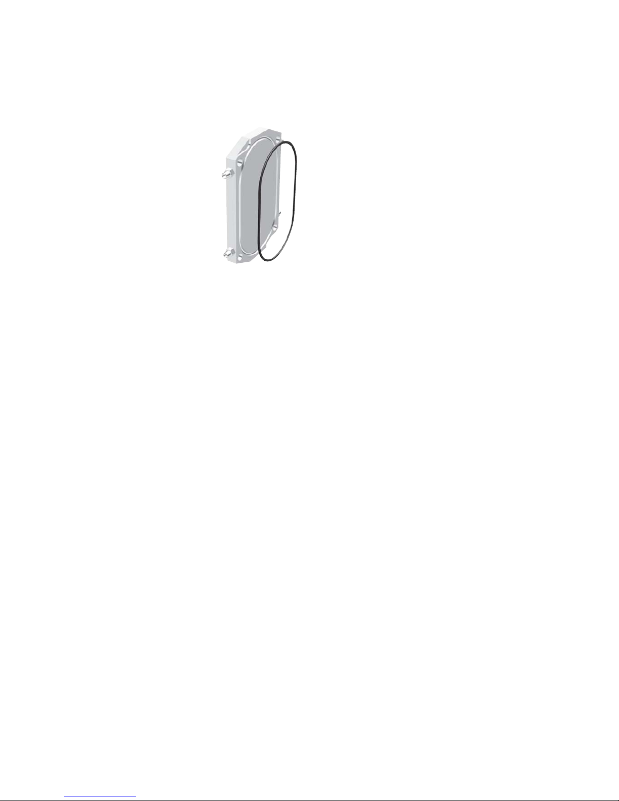
2.8 Heating and cooling jackets
All TopWing models can be supplied with pump covers with channels for heating or
cooling.
The reason for having this possibility is mainly used for bringing the medium inside the
rotor case on temperature before starting up the pump. This option is not meant to heat,
cool or maintain the temperature of the pumped medium in the process. The pre-heating
or cooling of the pump cover should be integrated in the heating or cooling system of the
installation.
The pump cover with or without safety relief valve for heating/cooling is provided with
two holes drilled straight through the cover. The heat is transferred to the rotor case via
the contact faces between cover and rotor case.
The heating/cooling channels in the pump cover together with the flush holes of the shaft
seal are positioned in such a way that the required thermal effects on the built-on safety
relief valve, rotor case and shaft seal are the best.
The pressure rating at the ports of the pump cover for heating/cooling is 10 bar and
should not be exceeded without contacting Johnson Pump for advice.
For start-up and shut-down procedures where heating/cooling devices are employed, the
heating/cooling medium should circulate 20-45 minutes before start-up and/or shutdown. When CIP/SIP cycle is employed as a part of the process, the heating/cooling
medium should continue to circulate during the cleaning/sterilizing process.
Heating/cooling jacket
Page 21
19
A.0500.301/314.B – IM-TW/10.00 GB (0401)
C
D
C
A
B
3.0 Technical data
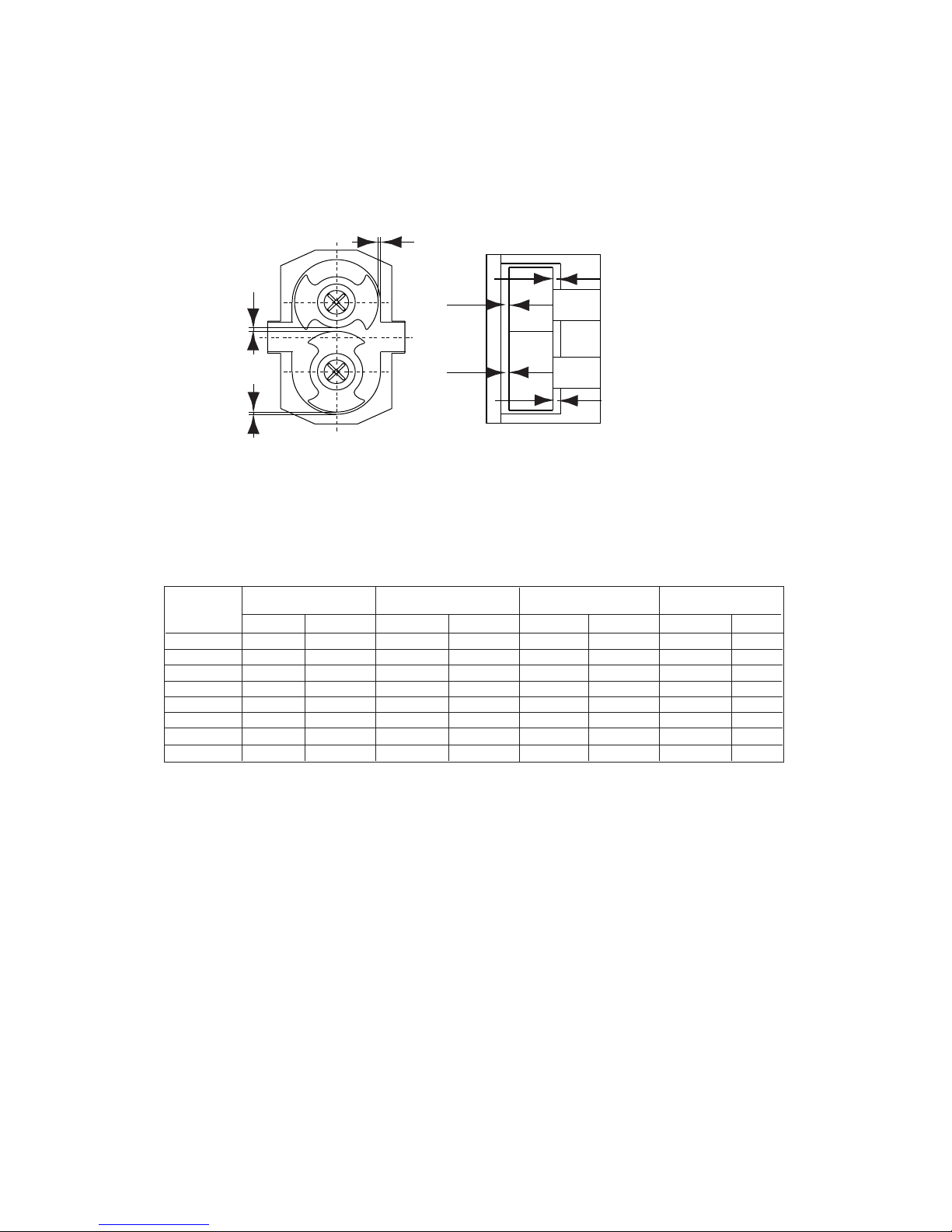
3.1 Rotor clearances
Clearances for liquid temperature of max 150°C.
A= Axial clearance rotor/pump cover
B=Axial clearance rotor/back side rotor case
C=Radial clearance rotor/rotor case top and side
D= Clearance rotor/rotor
Pump type A [mm] B [mm] C [mm] D [mm]
min max min max min max min max
TW1/0041 0.080 0.105 0.04 0.12 0.05 0.12 0.05 0.14
TW1/0082 0.100 0.125 0.05 0.14 0.08 0.15 0.07 0.16
TW2/0171 0.125 0.150 0.10 0.20 0.10 0.17 0.09 0.19
TW2/0343 0.135 0.160 0.11 0.20 0.12 0.20 0.12 0.21
TW3/0537 0.150 0.175 0.12 0.23 0.12 0.22 0.13 0.23
TW3/1100 0.165 0.190 0.14 0.25 0.14 0.24 0.15 0.25
TW4/1629 0.200 0.225 0.18 0.305 0.17 0.30 0.18 0.31
TW4/3257 0.225 0.250 0.22 0.34 0.20 0.33 0.22 0.35
Page 22
20 A.0500.301/314.B – IM-TW/10.00 GB (0401)
Recommended oils
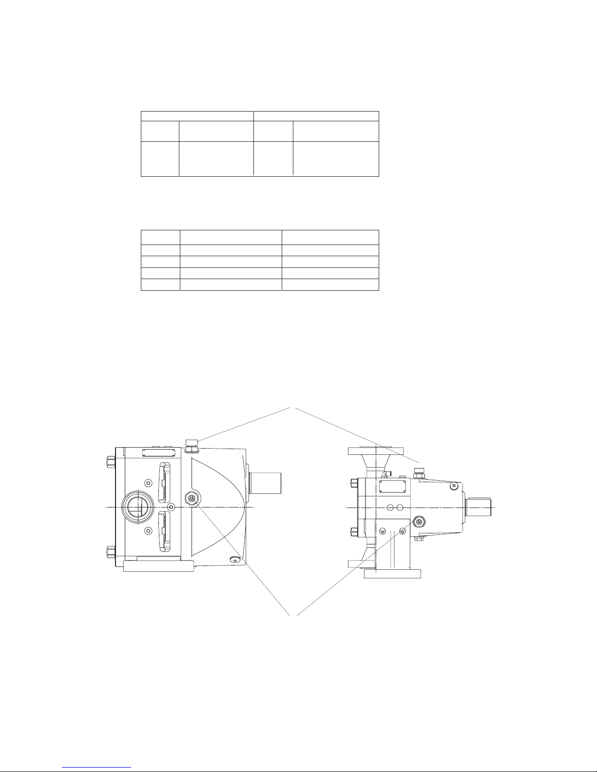
Oil volume
After filling up oil, check the oil level in the oil level glass.
Location of the oil level glass and the air breather
Example of typical oils Required characteristics
Ambient
Make Type Grade operating temp.
Shell Omala EP150 -18°C to 0°C
BP Energol GRXP EP220 0°C to 30°C
Esso Spartan EP320 30°C to 150°C
Pump Horizontal connection Vertical connection
TW1 0.26 l 0.22 l
TW2 0.63 l 0.40 l
TW3 1.60 l 0.73 l
TW4 4.00 l 1.75 l
Air breather
Oil level glass
Horizontal
Vertical
3.2 Oil volume in gearboxes
Page 23
21
A.0500.301/314.B – IM-TW/10.00 GB (0401)
0190
0120
0050
0051
0121
0010
0020
0030
0250
0070
0450
0172
TW1
3.3 Material specification
3.3.1 Machined parts – Pump
Reference catalogue: Stahlschlüssel 2001 (steel page 250 – 256 / stainless steel page 492 – 494)
Johnson Pump Europe USA Pump type
Pos. Description material description DIN W.-nr. TW1 TW2 TW3 TW4
0010 Rotor case GX2CrNiMoN19-11-2 EN 10213-4 1.4409 A351 CF3M X X X X
0020 Rotor X3CrNiMon27-5-2 EN 10088-3 1.4460 AISI 329(L) X X X X
0030 Pump cover X2CrNiMo 17-12-2 EN 10088-3 1.4404 AISI 316L X X X X
0050 Drive shaft
X3CrNiMon27-5-2 EN 10088-3 1.4460 AISI 329(L) X X X X
0051 Lay shaft
0070 Foot GX5-CrNi19-10 EN 10213-4 1.4308 A351 CF8 X X X X
0120 End cover GX5-CrNi19-10 EN 10213-4 1.4308 A351 CF8 X X X X
0121 Bearing holder 2C45 EN 10083-1 1.1191 SAE 1045 X X X X
0172 Pressure flange 2C45 EN 10083-1 1.1191 SAE 1045 X – – –
0190 Gear, 1 pair 16MnCr5 EN 10025-2 1.7131 SAE 2127 X X X X
0250 Retainer X3CrNiMon27-5-2 EN 10088-3 1.4460 AISI 329(L) X X X X
0450 Cap nut A4 ISO 3506-2 1.4401 AISI 316 X X X X
Page 24
22 A.0500.301/314.B – IM-TW/10.00 GB (0401)
ve
4xvd
sp
vh
da
vb
vc
df
de
ze
2xG1/8
vf
dc
db
ea
tb
zc
cb
ea
eb
ec
ed
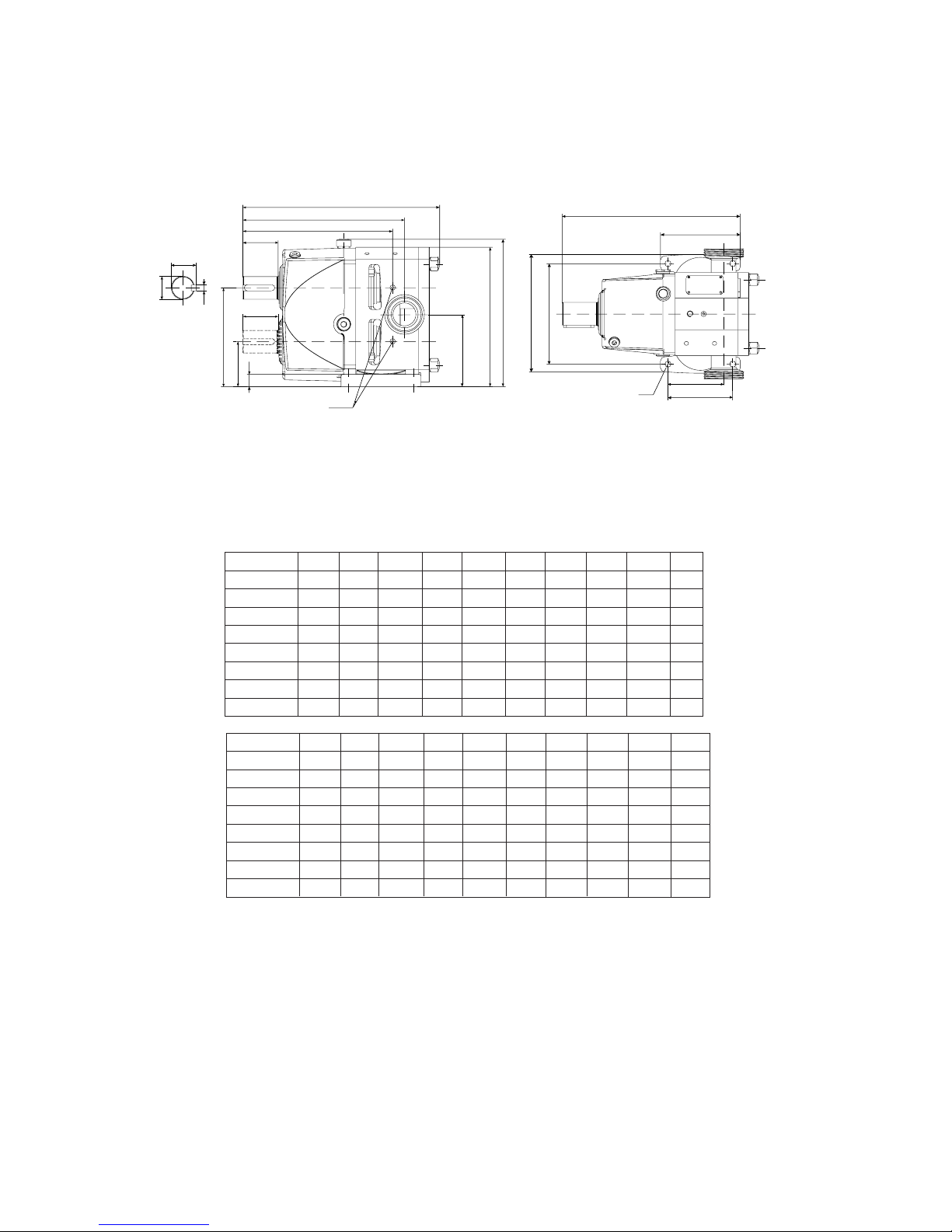
3.4 Dimensional drawings and weights
3.4.1 Standard
Flanges, see 3.4.3
Pump shown with seal flush.
Broken line shaft shows position for bottom drive version.
All dimensions in mm
Pump type cb da db dc de df ea eb ec ed
TW1/0041 170 208 113.5 55.5 160.5 177 28 6 21.5 19
TW1/0082 170 208 113.5 55.5 160.5 177 28 6 21.5 19
TW2/0171 245 291 162 74 228 242 58 10 41 38
TW2/0343 245 291 162 74 228 242 58 10 41 38
TW3/0537 310 370 215.5 98.5 305.5 294 82 14 51.5 48
TW3/1100 310 370 215.5 98.5 305.5 294 82 14 51.5 48
TW4/1629 423.5 498 297 135 423 431 140 20 74.5 70
TW4/3257 423.5 498 297 135 423 431 140 20 74.5 70
Pump Type sp tb vb vc vd ve vf vh zc ze
TW1/0041 65.5 225 110 135 10 74 15 95 187 84.5
TW1/0082 80.5 246 110 135 10 74 15 95 202 84.5
TW2/0171 91.5 322 164.5 195 10 106 20 130 264 118
TW2/0343 116 353 164.5 195 10 106 20 130 289 118
TW3/0537 118 410 213 254 14 134 25 170 336 157
TW3/1100 148 455 213 254 14 134 25 170 366 157
TW4/1629 138.5 563 312 376 17.5 160 30 200 459 216
TW4/3257 182.5 627 312 376 17.5 160 30 200 503 216
Regarding dimensions and weights of separate valves, see ’’H – Valves’’
Page 25
23
A.0500.301/314.B – IM-TW/10.00 GB (0401)
df
db
vf
eb
ed
ec
ea
zc
tb
4x
vd
vh
da
dd
vg
dd
vk
cb
sp
ve
2xG
1/8"
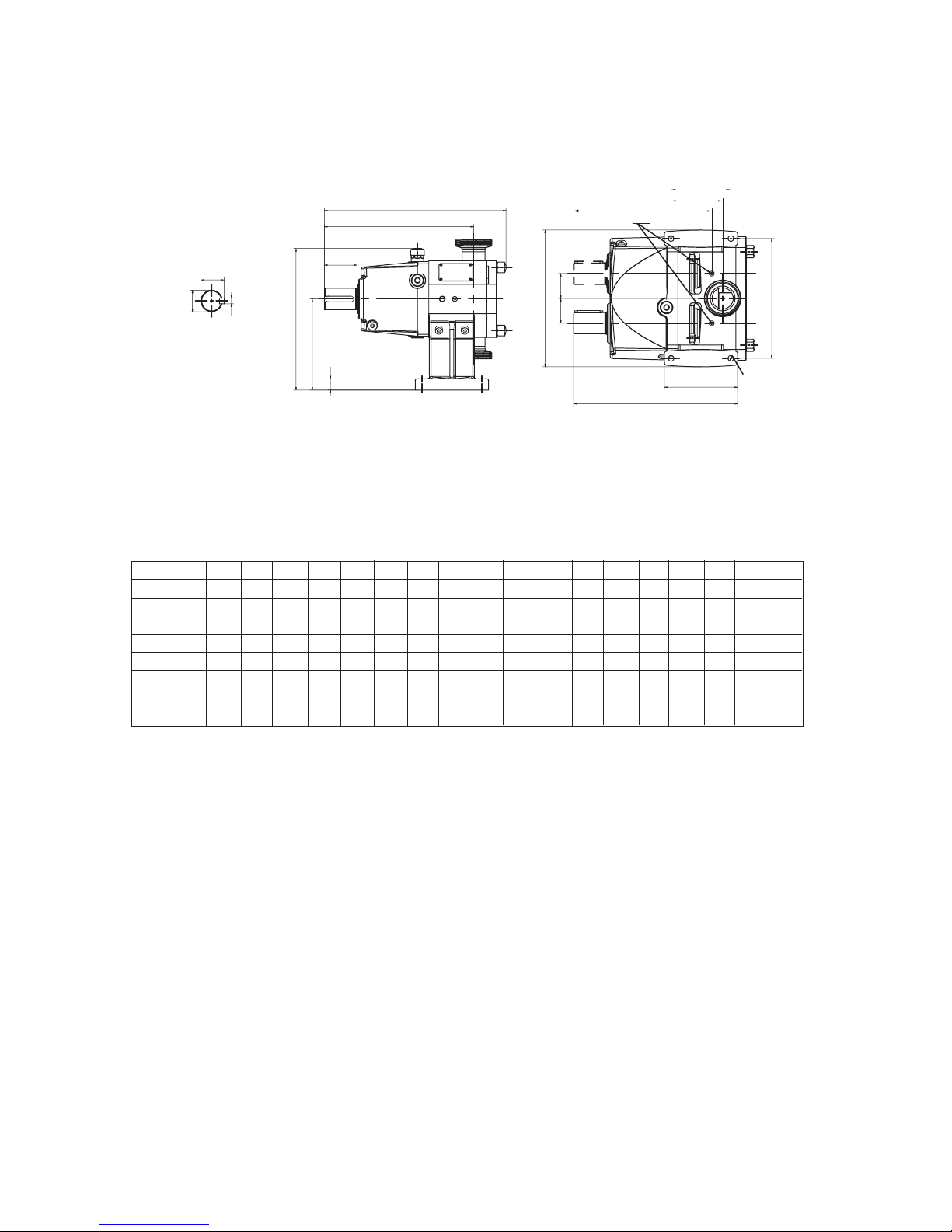
3.4.2 Vertical mounting
Flanges, see 3.4.3
All dimensions in mm
Pump shown with seal flush.
Broken line shaft position for LH drive version.
Pump type cb da db dd df ea eb ec ed sp tb vd ve vf vg vh vk zc
TW1/0041 170 208 113.5 29 177 28 6 21.5 19 65.5 225 10 74 15 174 95 150 187
TW1/0082 170 208 113.5 29 177 28 6 21.5 19 80.5 246 10 74 15 174 95 150 202
TW2/0171 245 291 162 44 242 58 10 41 38 91.5 322 10 106 20 242.5 130 212.5 264
TW2/0343 245 291 162 44 242 58 10 41 38 116 353 10 106 20 242.5 130 212.5 289
TW3/0537 310 370 215.5 58.5 294 82 14 51.5 48 118 410 14 134 25 327 170 286 336
TW3/1100 310 370 215.5 58.5 294 82 14 51.5 48 148 455 14 134 25 327 170 286 366
TW4/1629 423.5 498 297 81 444 140 20 74.5 70 138.5 563 17.5 160 30 466 200 402 459
TW4/3257 423.5 498 297 81 444 140 20 74.5 70 182.5 627 17.5 160 30 466 200 402 503
Regarding dimensions and weights of separate valves, see ’’H – Valves’’
Page 26
24 A.0500.301/314.B – IM-TW/10.00 GB (0401)
zb
zb
zb
zb
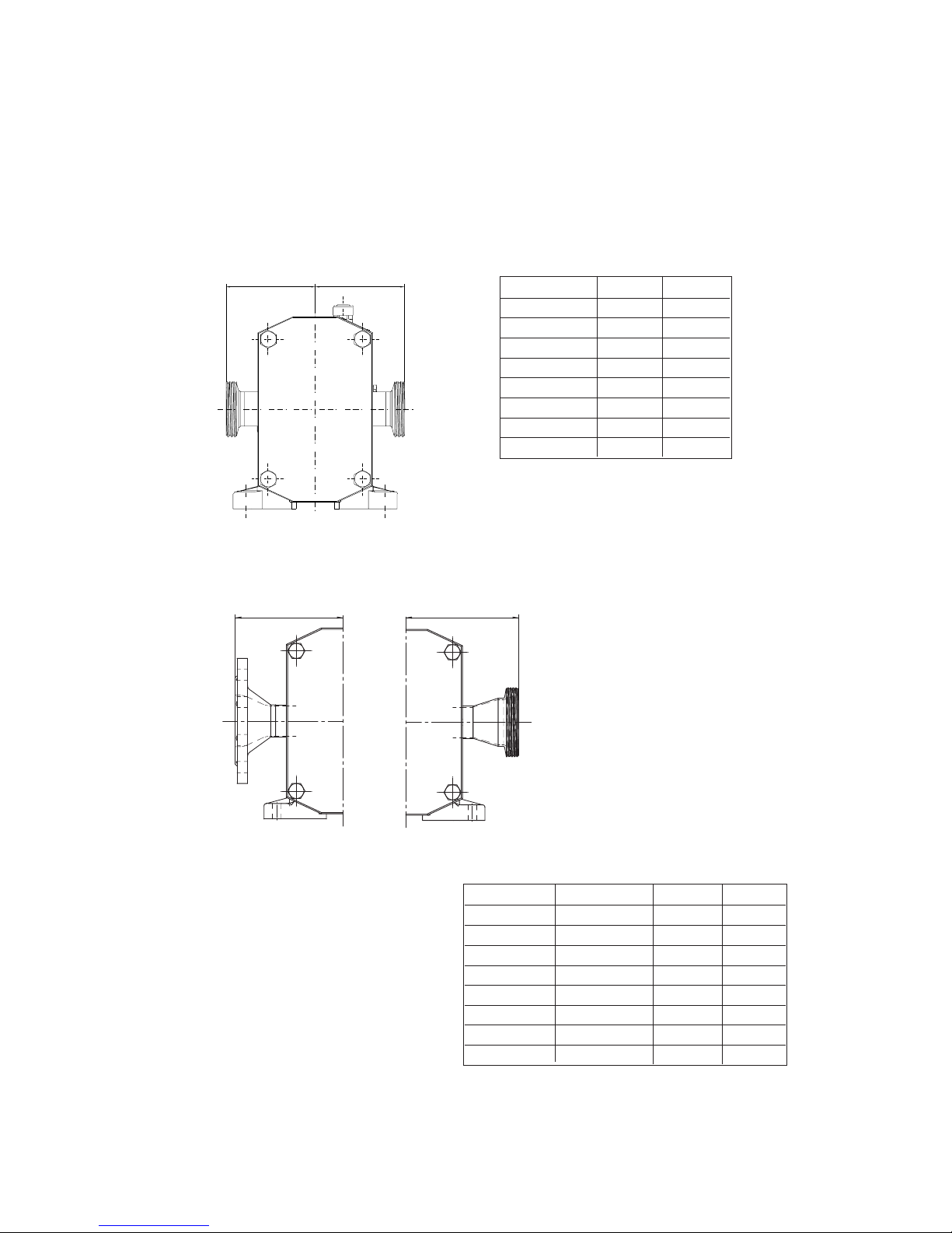
All dimensions in mm
All dimensions in mm
zb for flange
zb for thread connections
Pump type 1-zb 2-zb
TW1/0041 85 117
TW1/0082 85 117
TW2/0171 107 139
TW2/0343 107 139
TW3/0537 131 163
TW3/1100 136 168
TW4/1629 178 210
TW4/3257 182 212
Pump type Enlarged inlet 2-zb 1-zb
TW1/0041 25/40 117 125
TW1/0082 25/40 117 125
TW2/0171 40/50 139 147
TW2/0343 50/80 149 157
TW3/0537 50/80 173 181
TW3/1100 80/100 168 178
TW4/1629 80/100 210 220
TW4/3257 100/150 212 222
1 = All thread connections (DIN, SMS, DS, BS, ISO, GAS THREAD, NPT
THREAD) and all clamp connections (ISO, SMS, DIN)
2 = All flanges DIN (PN16) and ANSI (class 150)
3.4.3 Flanges
3.4.3.1 Standard pump
3.4.3.2 Enlarged inlet
Page 27
25
A.0500.301/314.B – IM-TW/10.00 GB (0401)
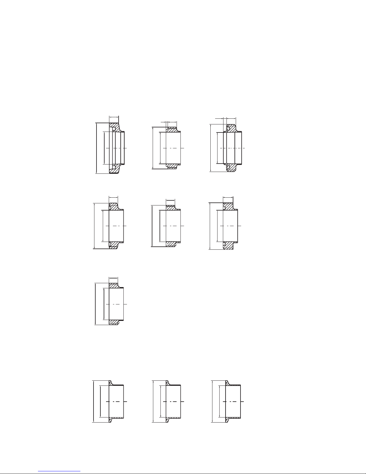
Thread connections
DIN 11851/
DIN 405
ISO 2853
BS 4825
SMS 1145
GAS THREAD
DS 722
NPT THREAD
ISO 2852
SMS 3017
DIN 32676
Clamp connections
d2
d1
d2
d1
d2
d1
d2
d1
d2
d1
d2
d1
3
b
b
b
4.8
b
b
d2
d1
d2
d1
d2
d1
d2
d1
b
b
3.4.4 Thread and clamp connections
Dimension table, see page 26
Page 28
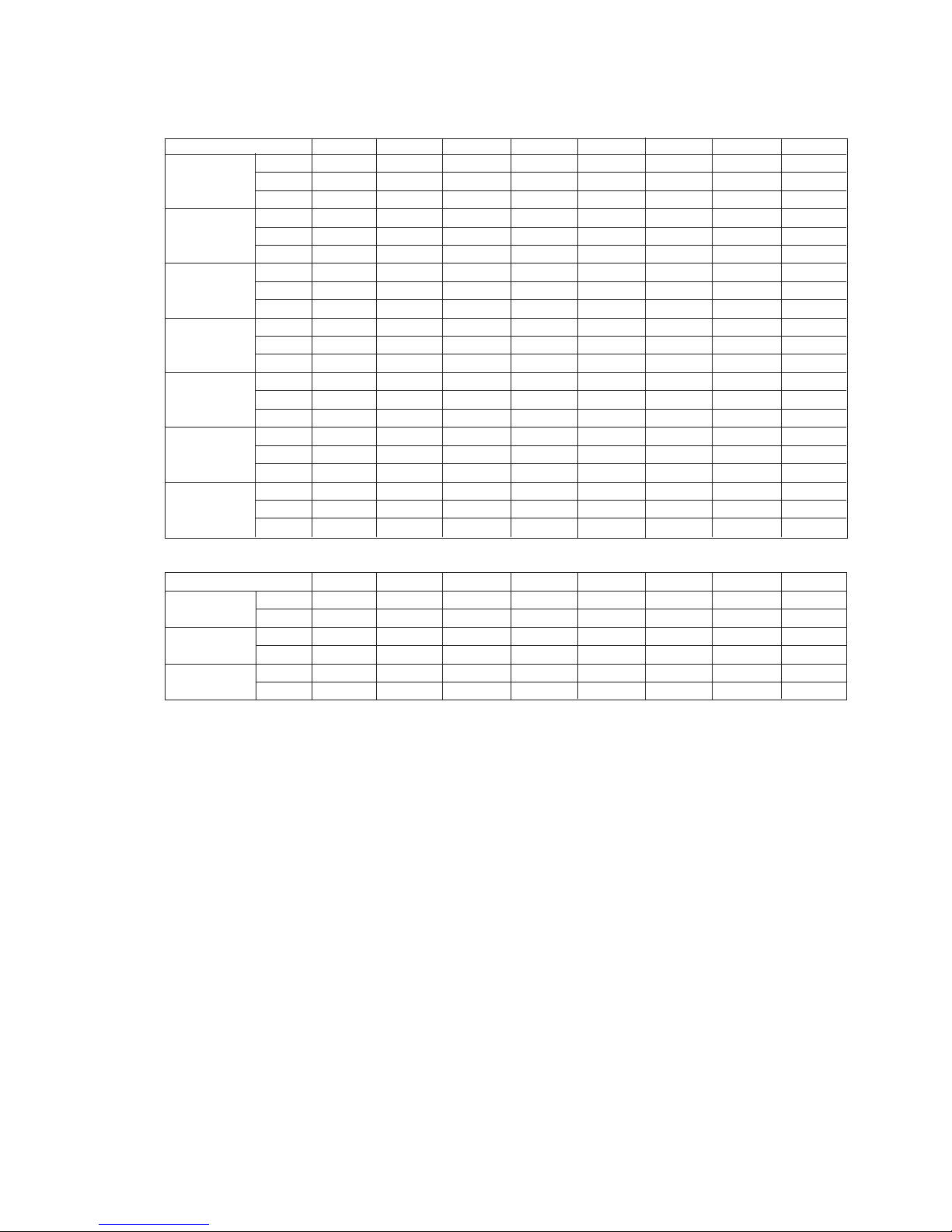
26 A.0500.301/314.B – IM-TW/10.00 GB (0401)
Dimensions – Thread and clamp connections
All dimensions in mm
THREAD CONNECTIONS TW1/0041 TW1/0082 TW2/0171 TW2/0343 TW3/0537 TW3/1100 TW4/1629 TW4/3257
DIN 11851/
d2 Rd 52x1/6 Rd 52x1/6 Rd 65x1/6 Rd 78x1/6 Rd 78x1/6 Rd 110x1/6 Rd 110x1/6 Rd 130x1/6
DIN 405 d1 26 26 38 50 50 81 81 100
b 141414 14142020 20
d2 ±0.08 37.05 37.05 52.6 64.08 64.08 91.11 91.11 –
ISO 2853 d1 22.6 22.6 37.6 48.5 48.05 72.9 72.09 –
b 13.5 13.5 13.5 13.5 13.5 13.5 13.5 –
d2 ±0.15 45.56 45.56 58.26 72.56 72.56 97.97 97.97 123.37
BS 4825 d1 22.2 22.2 34.9 47.6 47.6 73 73 97.6
b 14.3 14.3 14.3 14.3 14.3 14.3 14.3 14.3
d2 Rd 40x1/6 Rd 40x1/6 Rd 60x1/6 Rd 70x1/6 Rd 70x1/6 Rd 98x1/6 Rd 98x1/6 Rd 132x1/6
SMS 1145 d1 22.6 22.6 35.5 48.5 48.5 72 72 97.6
b 111115 15151919 25
GAS THREAD
d2 R 1" R 1" R 1 1/2" R 2" R 2" R 3" R 3" R 4"
ISO 7/1 d1 22.6 22.6 37.6 48.5 48.5 72 72 97.6
b 141414 14142020 20
d2 Rd 44x1/6 Rd 44x1/6 Rd 58x1/6 Rd 72x1/6 Rd 72x1/6 Rd 100x1/6 Rd 100x1/6 –
DS 722 d1 22.6 22.6 35.5 48.5 48.5 72 72 –
b 13.5 13.5 13.5 15.5 15.5 16.5 16.5 –
NPT THREAD
d2 1" NPT 1" NPT 1 1/2" NPT 2" NPT 2" NPT 3" NPT 3" NPT 4" NPT
ASA B 2.1 d1 22.6 22.6 37.6 48.5 48.5 72 72 97.6
b 141414 14142020 20
CLAMP CONNECTIONS
ISO 2852 d2 50.5 50.5 64 64 64 91 91 119
d1 22.6 22.6 37.6 48.5 48.5 72.9 72.9 97.6
SMS 3017 d2 50.5 50.5 50.5 64 64 91 91 119
d1 22.6 22.6 35.6 48.5 48.5 72.9 72.9 97.6
DIN 32676 d2 50.5 50.5 50.5 64 64 106 106 119
d1 26 26 38 50 50 81 81 100
Page 29
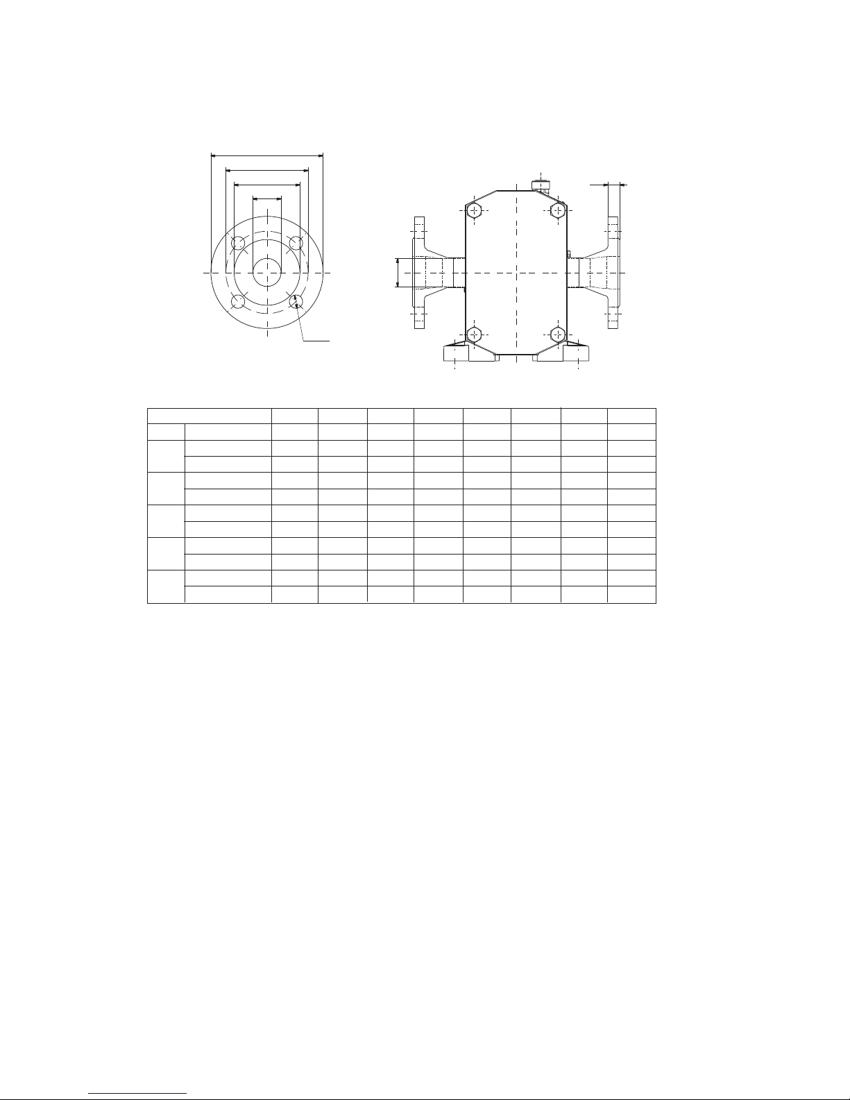
27
A.0500.301/314.B – IM-TW/10.00 GB (0401)
ad
ac
ab
aa
nxøak
am
aa
3.4.5 DIN and ANSI flanges
All dimensions in mm
TW1/0041 TW1/0082 TW2/0171 TW2/0343 TW3/0537 TW3/1100 TW4/1629 TW4/3257
aa 22.6 22.6 37.6 48.5 48.5 72 72 97.6
ab
PN16 68 68 88 102 102 138 138 158
ANSI Class 150 50.8 50.8 73 92.1 92.1 127 127 157.2
ac
PN16 85 85 110 125 125 160 160 180
ANSI Class 150 79.4 79.4 98.4 120.7 120.7 152.4 152.4 190.5
ad
PN16 115 115 150 165 165 200 200 220
ANSI Class 150 108 108 127 152.4 152.4 190.5 190.5 228.6
nxøak
PN16 4xø14 4xø14 4xø18 4xø18 4xø18 8xø18 8xø18 8xø18
ANSI Class 150 4xø15.9 4xø15.9 4xø15.9 4xø19.1 4xø19.1 4xø19.1 4xø19.1 8xø19.1
am
PN16 16 16 16 18 18 20 20 20
ANSI Class 150 14.3 14.3 17.5 19.1 19.1 23.8 23.8 23.8
Page 30

28 A.0500.301/314.B – IM-TW/10.00 GB (0401)
All weights in daN, mass is kg.
Pump type Standard pump Vertical mounting
weight weight
TW1/0041 14.5 15
TW1/0082 16.5 17
TW2/0171 38.5 40
TW2/0343 44 45.5
TW3/0537 87 90
TW3/1100 101 104
TW4/1629 245 252
TW4/3257 286 293
3.5 Weights
3.5.1 Weights standard pump
Page 31
29
A.0500.301/314.B – IM-TW/10.00 GB (0401)
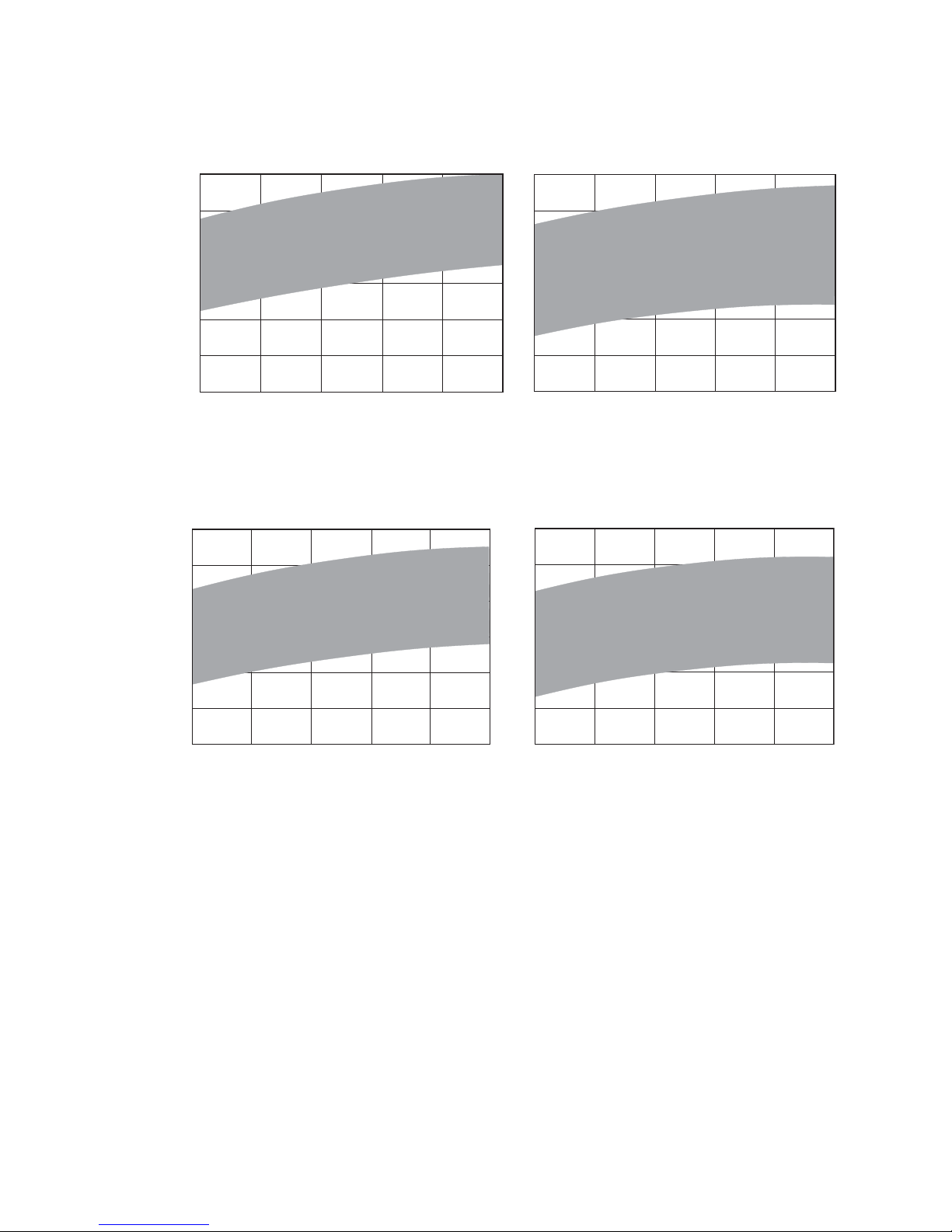
3.6 Sound level
dB(A)
0 Max
Differential pressure - bar
90
88
86
84
82
80
dB(A)
TW1 – Max. rpm TW2 – Max. rpm
0 Max
Differential pressure - bar
94
92
90
88
86
84
dB(A)
0 Max
Differential pressure - bar
100
98
96
94
92
90
dB(A)
TW3 – Max. rpm
0 Max
Differential pressure - bar
TW4 – Max. rpm
85
83
81
79
77
75
Page 32

30 A.0500.301/314.C – IM-TW/10.00 GB (0401)
4.0 Disassembly and assembly instructions
4.1 Tools to be used
Type Size TW1 TW2 TW3 TW4
Combination spanner 10 mm X
Combination spanner 13 mm X X
Combination spanner 17 mm X
Combination spanner 19 mm X X X X
Combination spanner 22 mm X X X X
Combination spanner 24 mm X
Combination spanner 30 mm X
Hexagon (Allen) key 4 mm X
Hexagon (Allen) key 5 mm X
Hexagon (Allen) key 6 mm X X X X
Hexagon (Allen) key 8 mm X X X X
Hexagon (Allen) key 10 mm X
Hexagon (Allen) key - Socket driven 4 mm X
Hexagon (Allen) key - Socket driven 5 mm X
Hexagon (Allen) key - Socket driven 6 mm X X X X
Hexagon (Allen) key - Socket driven 10 mm X X X X
Hexagon key - Socket driven 13 mm X X
Hexagon key - Socket driven 17 mm X
Hexagon key - Socket driven 19 mm X X X X
Hexagon key - Socket driven 22 mm X X X X
Hexagon key - Socket driven 24 mm X
Hexagon key - Socket driven 30 mm X
Torque wrench Adjustable up to min. xx Nm X
Torque wrench Adjustable up to min. xx Nm X
Torque wrench Adjustable up to min. xx Nm X
Torque wrench Adjustable up to min. xx Nm X
Depth micrometer 0 – 25 mm X X X X
Feeler gauge set – X X X X
Retainer tool Supplied with pump X X X X
Hook spanner HN5 X
Hook spanner HN9/10 X
Hook spanner HN12/13 X
Hook spanner HN16/17 X
Soft-faced mallet X X X X
Steel hammer X X X X
Screwdriver XXXX
Ball bearing extractor X X X X
A selection of special tools is available, see chapter 5.0
Page 33

31
A.0500.301/314.C – IM-TW/10.00 GB (0401)
4.2 General instructions
Assembly and disassembly may be performed by qualified personnel only. Always wear
the appropriate safety clothing. Make sure that the personnel is properly instructed and
educated.
Insufficient or wrong assembly and disassembly can lead to the pump malfunction.
Johnson Pump is not liable for accidents and damage caused by non-compliance with the
guidelines.
Always work in a clean surrounding. Keep all highly sensitive parts such as seals,
bearings, etc. in their original packaging as long as possible.
Use a stainless steel work surface.
For maintenance and repair use only appropriate tools that are in good condition.
Check that the parts to be used have not been damaged during transport.
Never work on the pump in operation. In case of a disassembled pump, avoid any
contact with the rotors when turning the shaft manually.
Do not forget that the pump can be started even when the pump cover has been remo-
ved for e.g. cleaning. Never run the pump without pump cover.
After disassembly carefully clean the parts and check them for damage, especially the
mounting surfaces, and replace all damaged parts.
All parts fitted together at the disassembly must stay together when reinstalled,
especially the rotors, shafts, bearings and shims.
4.3 O-rings and lip seals
When working with lip seals or O-rings, take care not to damage them as they pass over
any sharp edges of splines, threads, etc. Be sure that the O-rings are not twisted in the
groove when installing.
All O-rings and sealing lips should be lightly lubricated with a suitable lubricant before
fitting, e.g. soap water.
For O-rings made of PTFE, it is advised to heat them up in hot water before placement.
A warmed up O-ring becomes more soft, thus easier to install.
4.4 Shutdown
Before starting the maintenance or inspection, follow the next steps to shut down the
pump.
1. Stop the pump. To prevent the motor from starting while you are working on the
pump follow the procedure below:
a) Turn off the pump at the electrical cabinet
b) Set the pump circuit breaker to off
c) Secure the circuit breaker from switching on with a lock. If not possible take the
fuses with you to the working place. Sign the electrical cabinet “out of work”
d) Remove, if necessary, the protection around the mechanical coupling only when
the pump has come to a complete standstill.
2. Let the pump cool down to the ambient temperature, if suitable for the liquid being
pumped.
3. Isolate and depressurise flushed product auxiliary services.
4. Close both suction and discharge valves.
5. Drain and purge the pump head and pipe work.
6. Clean the pump externally before disassembly.
Page 34
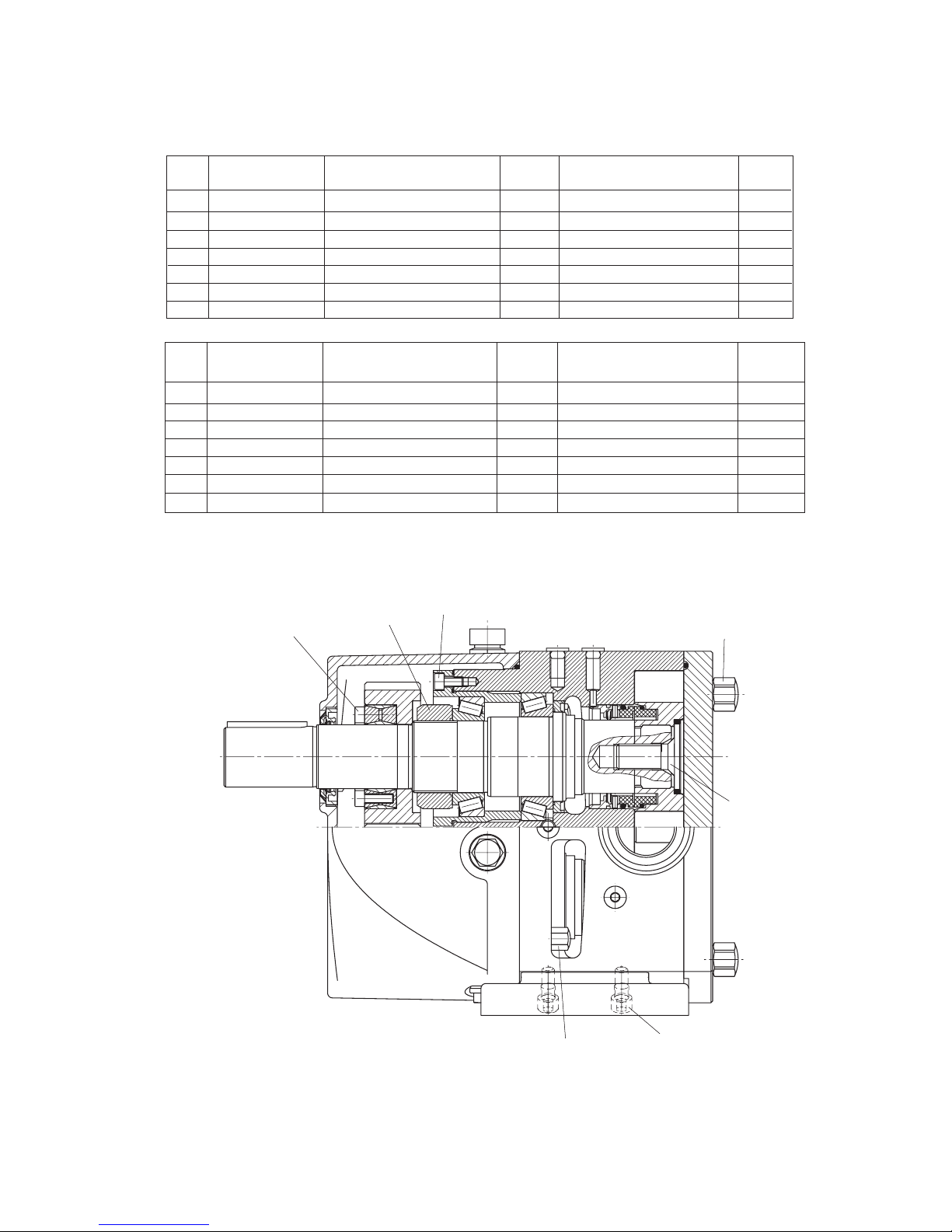
32 A.0500.301/314.C – IM-TW/10.00 GB (0401)
0250
0520
0620
0510
0450
0525
0455
4.5 Tightening torque [Nm] for nuts and screws
TW3 Torque TW4 Torque
Pos. Description Dimension [Nm] Dimension [Nm]
0250 Retainer M16 (X-3CrNiMoN27.5.2) 88 M20 (X-3CrNiMoN27.5.2) 179
0450 Cap nut M16-DIN917-(A4) 172 M20-DIN917-(A4) 250
0455 Cap nut M10-DIN917-(A4) 41 M12-DIN917-(A4) 71
0510 Screw M8x20-DIN912-(8.8) 21 M10x25-DIN912-(8.8) 41
0520 Screw M8x22-DIN912-(12.9) 22 M10x25-DIN912-(12.9) 42
0525 Screw M10x20-DIN912-(A4) 41 M12x25-DIN912-(A4) 71
0620 Locking nut (*) M55X2 SKF KMT11 (*) M80X2 SKF KMT16 (*)
(*) Locking nut Pos. 0620:
Tighten nut until friction torque measured on shaft = specified torque
See sectionn 4.7.3.
TW1 Torque TW2 Torque
Pos. Description Dimension [Nm] Dimension [Nm]
0250 Retainer M10 (X-3CrNiMoN27.5.2) 22 M16 (X-3CrNiMoN27.5.2) 69
0450 Cap nut M8-DIN917-(A4) 21 M10-DIN917-(A4 41
0455 Cap nut M6-DIN917-(A4) 8.5 M8-DIN917-(A4) 21
0510 Screw M5x12-DIN912-(8.8) 5 M6x12-DIN912-(8.8) 8.5
0520 Screw M5x20-DIN912-(12.9) 8.5 M6x18-DIN912-(12.9) 9
0525 Screw M6x16-DIN912-(A4) 8.5 M8x20-DIN912-(A4) 21
0620 Locking nut (*) M25X1.5 SKF KM5 (*) M45X1.5 SKF KMT9 (*)
Page 35
33
A.0500.301/314.C – IM-TW/10.00 GB (0401)
0450
0250
0801
0800
0020
0030
4.6 Disassembly
See also sections 4.2 General instructions, 4.3 O-rings and lip seals,
4.4 Shut down and 4.5 Tightening torque for nuts and screws.
4.6.1 Pump cover and rotor removal
Do not forget that liquid may still flow out of the rotor case when removing the pump
cover (0030).
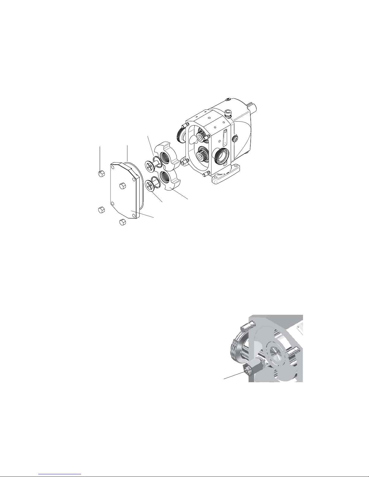
1. Remove the cap nuts (0450).
2. Cavities are provided diagonal on the mounting surface between cover and rotor
case to permit removing pump cover with aid of e.g. a screwdriver. Check the O-ring
(0801).
3. Lock the rotors by placing a block of soft material between the rotors.
4. Unscrew retainer (0250) counter clockwise by using the retainer tool.
5. Remove retainer O-ring (0800).
6. Remove the rotor (0020).
7. Remove the second rotor in the same way.
Retainer tool
Page 36
34 A.0500.301/314.C – IM-TW/10.00 GB (0401)
}
0083
0082
0082 0083
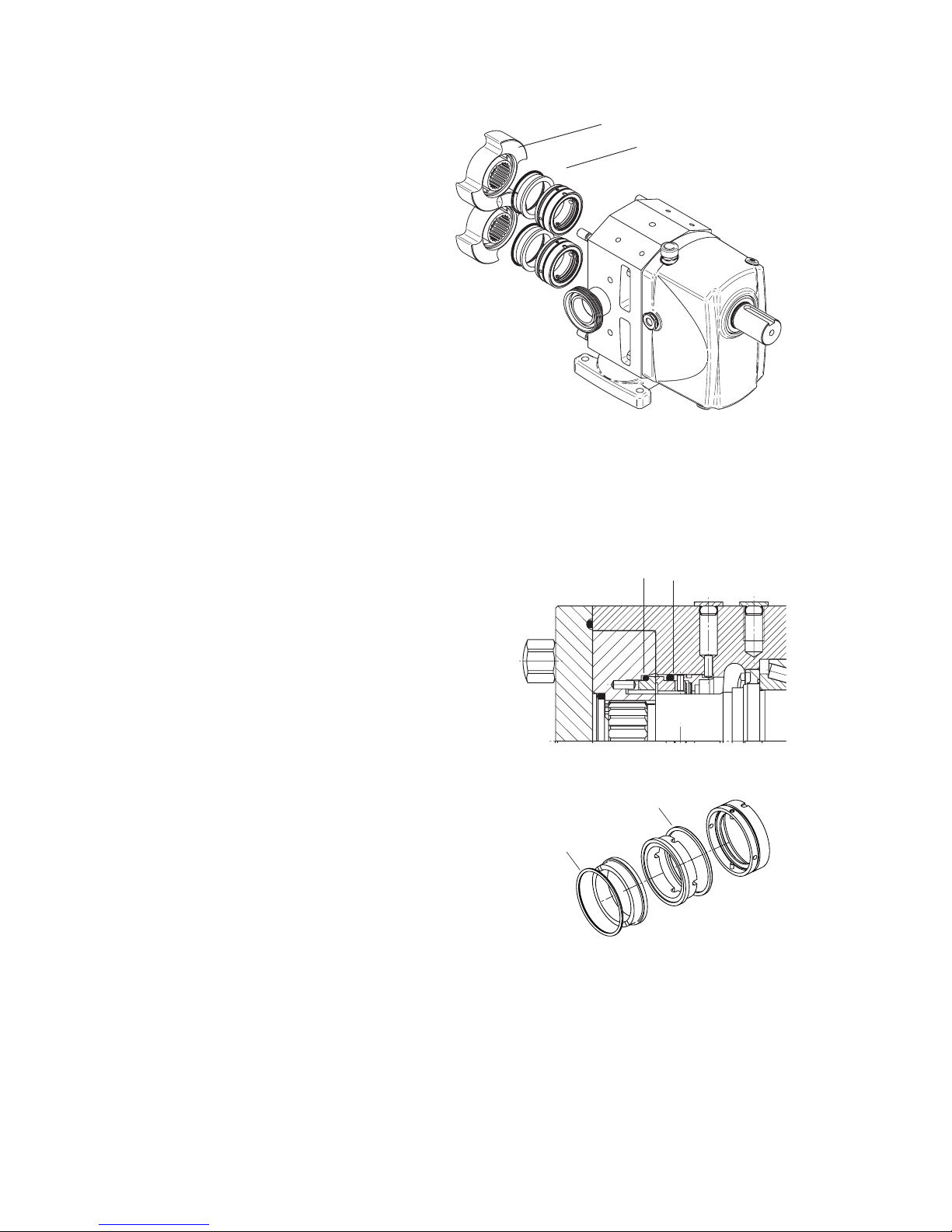
4.6.2.1 Single mechanical seal
1. Remove the rotating seal face
and O-ring (0082) from the rotor.
2. Remove the stationary seal face
together with O-ring (0083) from
the rotor case.
3. Remove the stationary part of the
seal together with the spring from
the rotor case.
4. Check O-rings (0082) and (0083).
5. Check condition of seal faces and
spring.
4.6.2 Disassembly of seals
Only if section 4.6.1 has been completed.
Rotor
Seal assembly
Page 37
35
A.0500.301/314.C – IM-TW/10.00 GB (0401)
0082
0083
0085
0082
0083
0085
0890
0082
0083
0085
0086
0087
0082
0083
0085
0086
0087
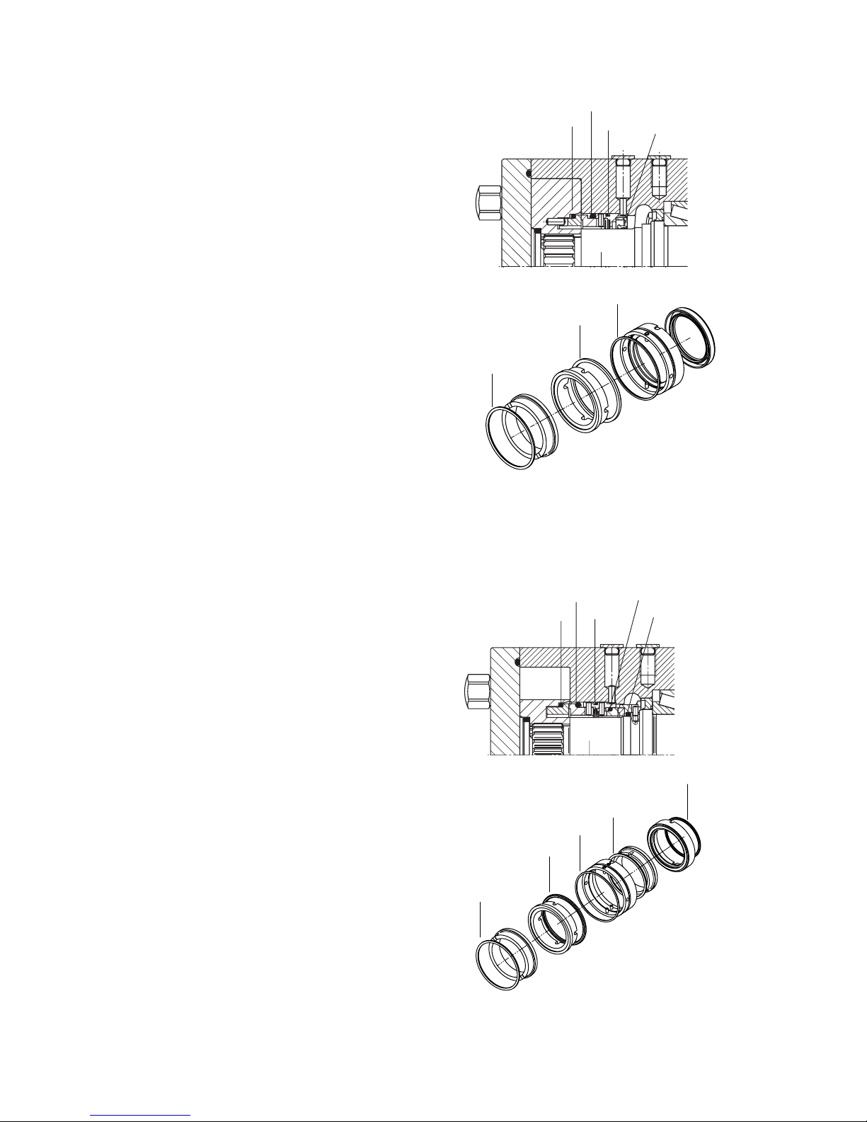
4.6.2.2 Single mechanical seal with flushing
1. Remove the rotating seal face
and O-ring (0082) from the rotor.
2. Remove the stationary seal face
together with the O-ring (0083)
from the rotor case.
3. Remove the stationary part of the
seal together with the O-ring
(0085), spring and lip seal (0890)
from the rotor case.
4. Remove lip seal (0890) from the
stationary part of the seal.
5. Check the conditions of O-rings,
4.6.2.3 Double mechanical seal
1. Remove the rotating seal face
and the O-ring (0082) from the
rotor.
2. Remove the product side stationary seal face together with
the O-ring (0083) from the rotor
case.
3. Remove the stationary part of
the seal together with O-ring
(0085) and spring from the rotor
case.
4. Remove the atmospheric side stationary seal face with O-ring
(0086) together with the rotating
seal face and O-ring (0087) from
the shaft.
Page 38
36 A.0500.301/314.C – IM-TW/10.00 GB (0401)
0082
0085
0183
0097
0130
0082
0085
0183
0082
0085
0183
0183
0085
0097
0130
0082
0085
0183
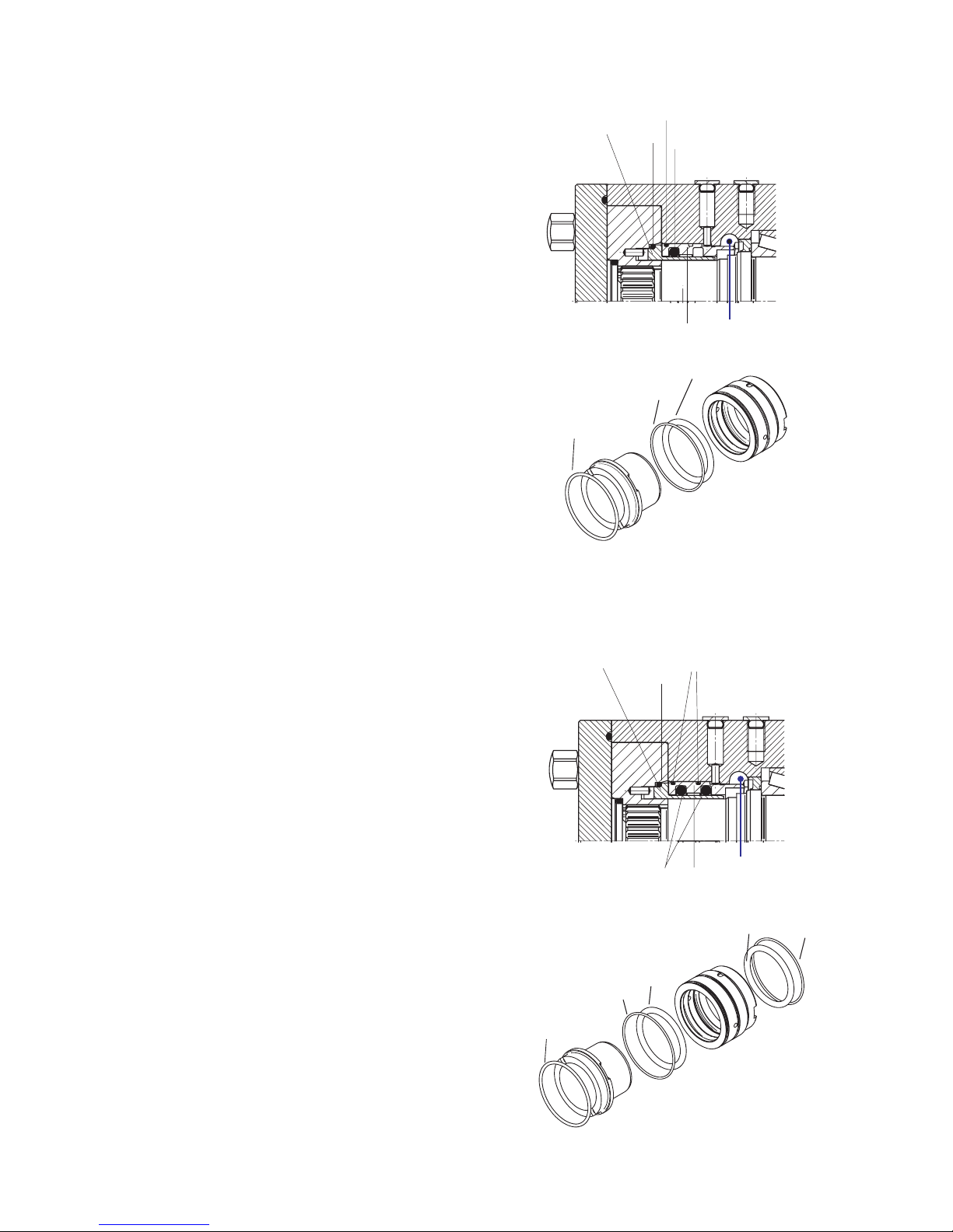
4.6.2.4 Single O-ring seal
1. Remove the shaft sleeve (0130)
from the shaft and O-ring (0082)
from the rotor.
2. Remove the support ring (0097)
together with O-ring (0085) and
O-ring (0183) from the rotor case.
The support ring can be pushed
out from the backside via the
access opening in the rotor case
(TW2-4).
On TW 1, please use special tool,
see section 5.7.
3. Remove the O-rings (0183) and
(0085) from the support ring
(0097).
4.6.2.5 Double O-ring seal
1. Remove the shaft sleeve (0130)
from the shaft and O-ring (0082)
from the rotor.
2. Remove the support ring (0097)
together with O-rings (0085) and
(0183) from the rotor case. The
support ring can be pushed out
from the backside via the access
opening in the rotor case
(TW2-4).
On TW 1, please use special tool,
see section 5.7.
3. Remove the O-rings (0183) and
(0085) from the support ring
(0097).
Push out
Page 39
37
A.0500.301/314.C – IM-TW/10.00 GB (0401)
0121
0510
0171
0611
0850
0870
0875
0855
0120
0181
0881
0455
0190
0652
0520
0651
}
TW 1
TW 2, 3, 4
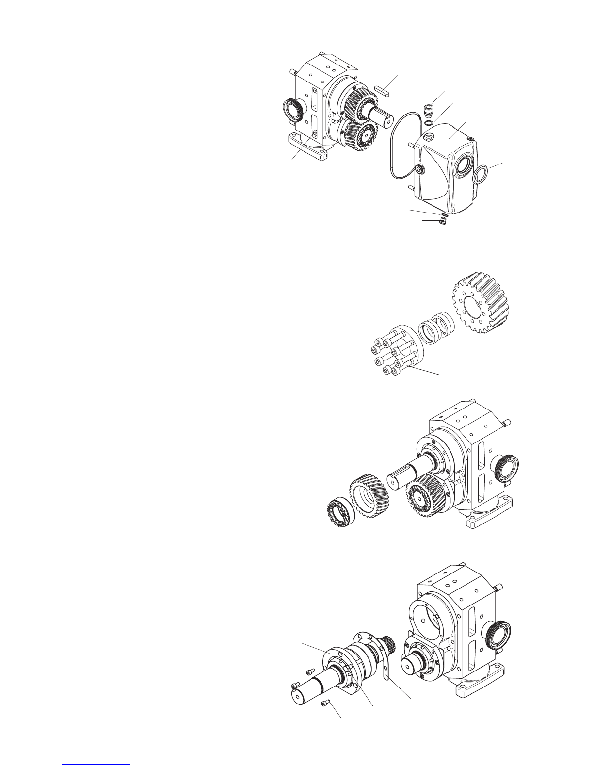
4.6.3 Disassembly of drive assembly
1. Disconnect the pump from the motor.
2. Remove key (0611).
3. Remove the air breather (0850) with sealing ring (0855)
and plug (0870) with sealing ring (0875). Drain the oil in an appropriate reservoir.
4. Unscrew the cap nuts (0455) in the access opening between hydraulic part and
bearings.
5. Remove the end cover (0120) with V-seal (0881) to the back.
6. Remove O-ring (0181) from the rotor case.
7. TW1
Loosen the screws (0520) cross-wise in several steps to
release the locking elements (0651) from the gear.
7. TW2, TW3, TW4
Loosen the screws of the locking assembly
(0652) crosswise in several steps to
release it from the gear.The locking
assembly is self-releasing.
8. Remove the gear (0190) together with
the locking assembly (0652) from the shaft.
(For TW1 locking elements (0651)).
9. Do this on both shafts.
10. Remove the screws (0510) from the
bearing holder (0121).
11. Screw 2 bolts in the 2 threaded holes in
the flanges of the bearing holder.
12. Tighten the bolts crosswise to pull the
bearing holder (0121) together with the
shaft and both bearings out of the rotor case.
13. Remove the shim (0171).
14. Do this on both shafts.
Page 40
38 A.0500.301/314.C – IM-TW/10.00 GB (0401)
0620
Set screw
Tool
0121
0701
(external ring)
Tool
0700
(internal ring )
To ol
0700
0701 (internal ring)
mounting surface
TW 2, 3, 4
0630
0620
TW 1
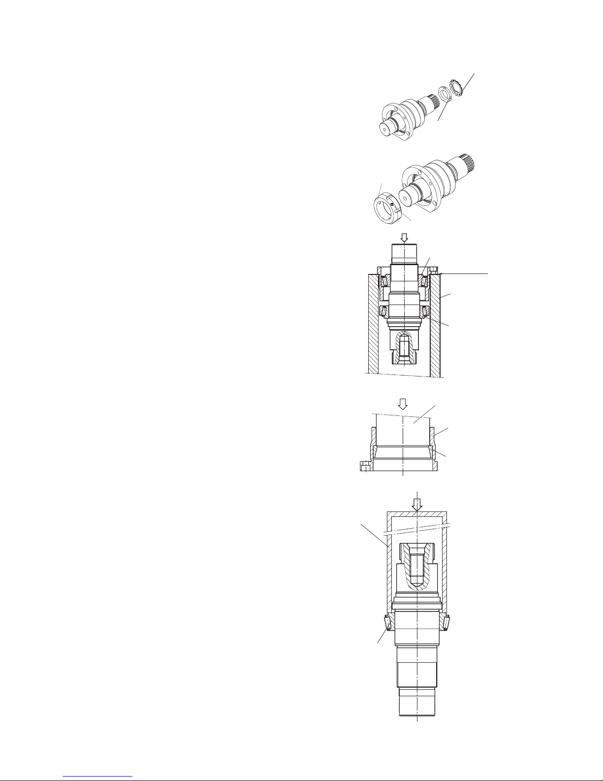
4.6.4 Disassembly of shaft arrangement
1. TW1
Bend the tooth straight out of the groove
of the nut and remove the locking
nut (0620) and remove it.
1. TW2, TW3, TW4
Loosen set screws of locking nut (0620)
and remove it.
2. Support the bearing holder on mounting
surface and press the internal ring of
bearing (0701) together with the shaft and
bearing (0700) out of the bearing holder.
Ensure that the mounting surface of the
bearing holder is not damaged.
3. Remove the bearing holder with external
part of bearing (0701) and the external
ring of bearing (0700) from the shaft.
4. Remove the external ring of bearing
(0701) from the bearing holder (0121).
5. Remove the internal ring of bearing
(0700) with rollers from the shaft.
6. Do the same for the second shaft.
Page 41
39
A.0500.301/314.C – IM-TW/10.00 GB (0401)
Tool
0700
(internal ring)
Shaft shoulder
0525
0885
0885
0525
Tool
0885
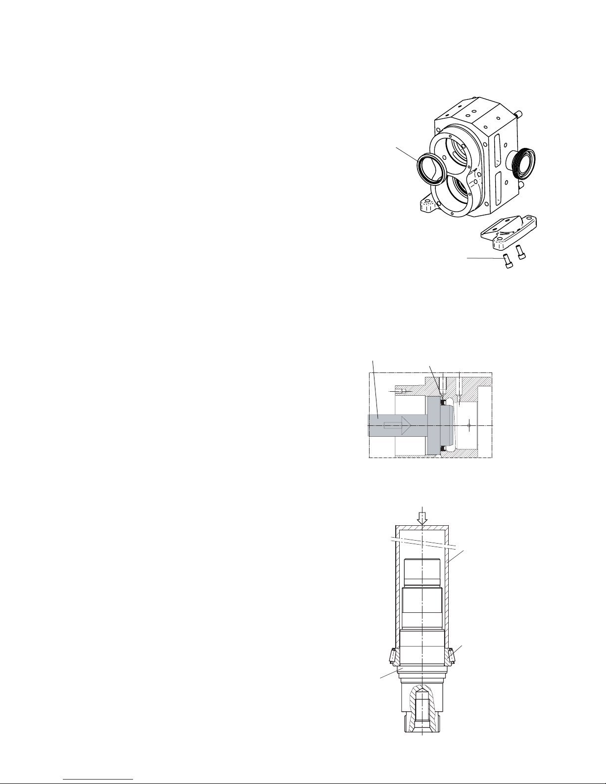
4.6.5 Disassembly of rotor case
1. Remove lip seals (0885) from rotor case.
2. If the feet have to be removed, loosen screws (0525) and remove feet.
4.7 Assembly
See also sections 4.2 General instructions, 4.3 O-rings and lip
seals and 4.5 Tightening torque for nuts and screws.
4.7.1 Pre-assembly of the rotor case
4.7.1.1 Foot assembly
1. Place the left foot on the rotor
case and tighten with screws
(0525). The small surface of the
foot must be in contact with the
bottom surface of the rotor case.
Make sure that the surfaces are
clean.
2. Place the right foot on the rotor
case and tighten with screws
(0525).
4.7.1.2 Assembly of lip seals
1. Fill the space between the lips
with grease.
2. Fit the lip seals (0885) into the
rotor case. The spring must point
in the direction of the bearing.
The lip seals must be aligned with
the axial surface inside the rotor
case.
4.7.2 Pre-assembly of shaft/
bearing arrangement
1. Heat the internal ring of bearing
(0700) up to 120°C.
2. Place the bearing on the shaft.
Ensure that the axial surface of
the internal ring of the bearing is
pushed properly against the shaft
shoulder.
Tool : assembly tool for lip seal
rotor case front end (see chapter 5.0)
Page 42
40 A.0500.301/314.C – IM-TW/10.00 GB (0401)
Tool
0701
(external ring)
0121
0121
0700
(external ring)
0701
(internal ring )
0620
Set screw
0630
0620
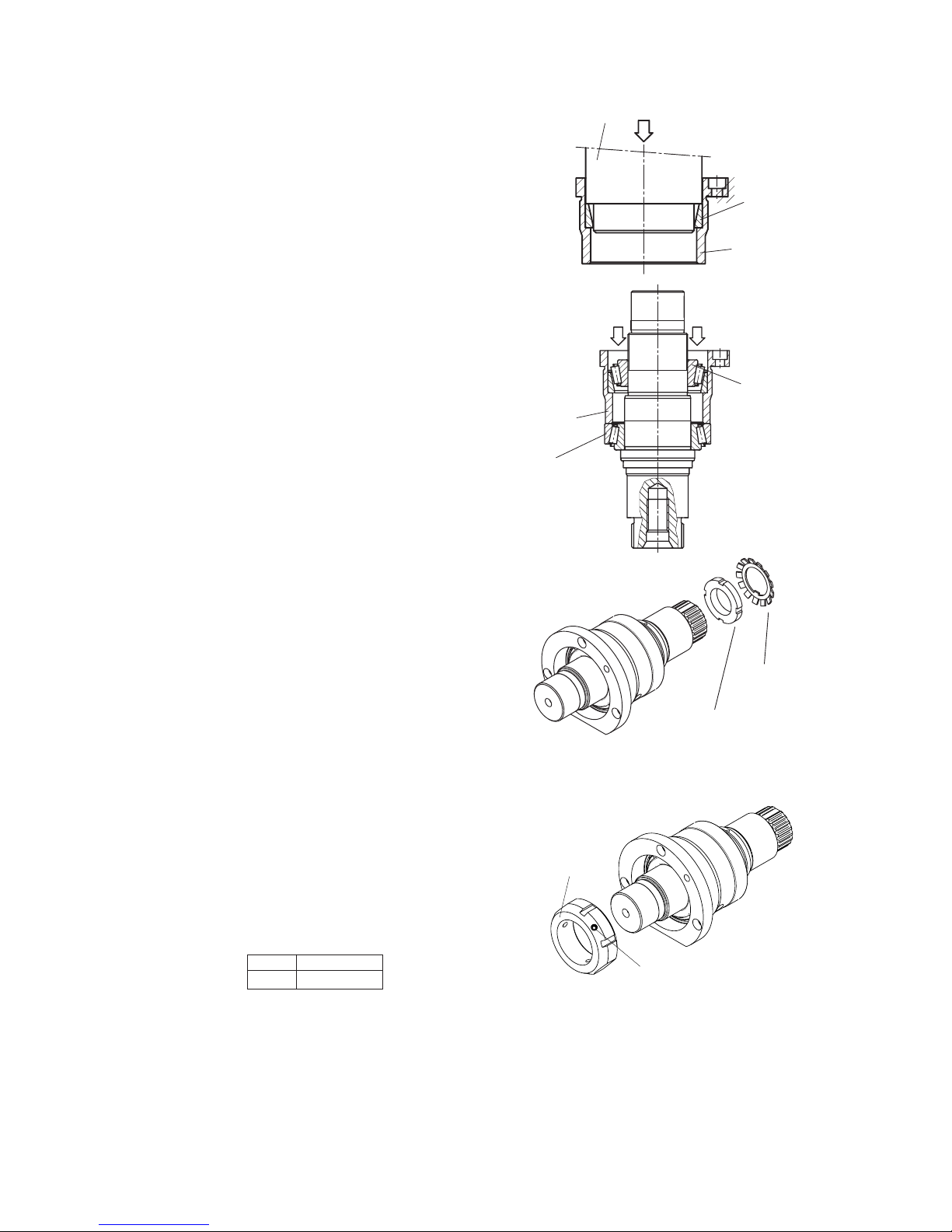
3. Fit the external ring of
bearing (0701) in the bearing
holder (0121). Ensure that the
axial surface of the bearing ring is
pushed properly against the
ounting surface inside the bearing
holder.
4. Place the shaft vertical on the
workbench and place the external
ring of bearing (0700) and the
bearing holder on the internal
ring of bearing (0700).
5. Heat the internal ring of bearing
(0701) up to 120°C and fit the
bearing on the shaft.
Wait until the parts are cooled
down to ambient temperature.
6. TW1
Place the locking washer (0630)
on the shaft and screw on locking
nut (0620) by hand until it makes
contact with the internal ring of
bearing (0701).
6. TW2, TW3, TW4
Screw on locking nut (0620) by
hand until it makes contact with
the internal ring of bearing
(0701).
Pump Torque
TW2–4 18 Nm
Page 43
41
A.0500.301/314.C – IM-TW/10.00 GB (0401)
0510
Tool
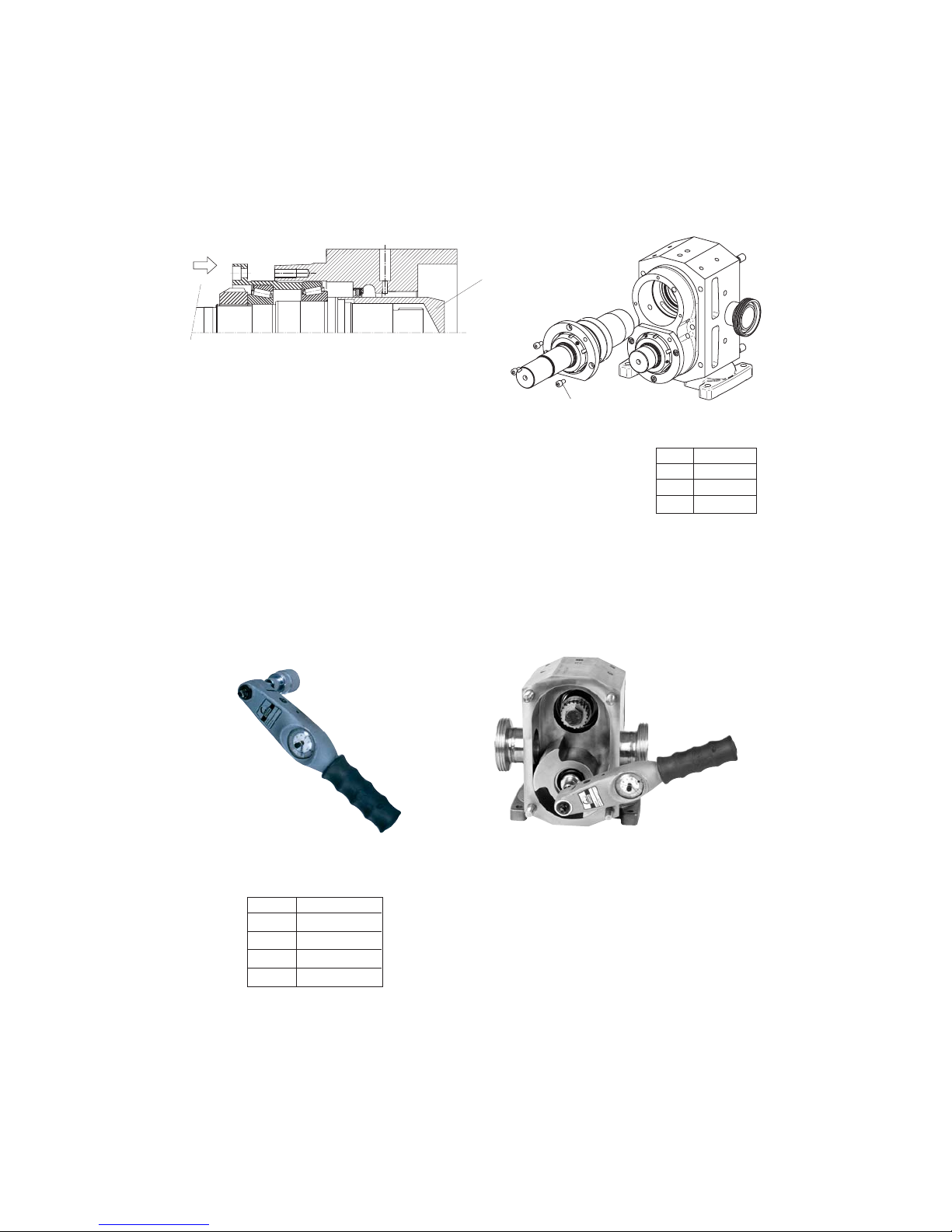
4.7.3 Assembly of shafts in the rotor case and setting of
the tapered roller bearings
1. Fit both pre-assembled shafts with bearings in the rotor case and fix them with
screws (0510).
2. Screw hexagon bolts in the threaded holes (retainer holes)
in the front faces of the shaft.
3. To check the friction torque and adjust the bearing setting of each shaft
separately do as follows:
• Use the torque meter wrench (see picture) on the hexagon bolt to
turn the shaft and measure the friction torque
• Remove the torque meter wrench
• Place one rotor on the shaft
Tool : assembly sleeve for lip seal
(see chapter 5.0)
Torque meter wrench only
Measuring friction torque
TW1 M10x20
TW2 M16x30
TW3 M16x30
TW4 M20x50
Pump Torque
TW1 1.6 – 1.8 Nm
TW2 3.2 – 3.4 Nm
TW3 4.5 – 4.7 Nm
TW4 7.0 – 7.3 Nm
Page 44
42 A.0500.301/314.C – IM-TW/10.00 GB (0401)
0620
X
• Remove the block of material
Repeat the steps (in point 3) until the correct friction torque setting is reached.
4. After that secure the locking nut
TW 1: by bending one tooth of the locking washer into a
groove of the locking nut
TW2, TW3, TW4: by tightening the set screws in the locking nut
(torque 18 Nm).
5. Adjust the bearings of the second shaft in the same way and remove hexagon bolts
from the shafts
4.7.4 Axial adjustment of the rotors
To adjust the position of the rotors on both shafts separately do as follows:
1. Fit the rotor on the shaft.
2. Place the O-ring on the retainer and assemble it to the shaft.
3. Tighten the retainer with specified torque to fix the rotor on the shaft (see section
4.5 Tightening torque for nuts and screws).
4. Measure the distance X from the front surface of the rotor to the front surface of
the rotor case.
Determine the required thickness of the shim [mm] by using the following
formula:
• Min. thickness of shim = measured distance X + min. axial clearance A
• Max. thickness of shim = measured distance X + max. axial clearance A
• Place a block of soft material (plastic or wood) between rotor and
rotor case to block the rotor against rotation
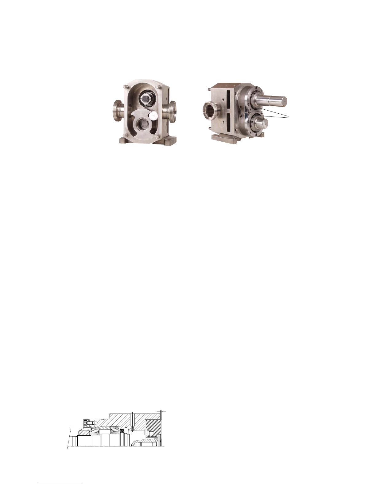
• Turn locking nut (0620) in order to adjust the pre-load of the
bearings according to the measured friction torque
Rotor locked with plastic block Locking nut of the pre-loading
For clearances see section 3.1 Rotor clearances.
Page 45
43
A.0500.301/314.C – IM-TW/10.00 GB (0401)
0510
0190
0652
0050
0051
0520
}
0651
TW 1
6. Adjust the thickness of the shim by peeling of the required number of layers of
0.025 mm (coloured).
7. Remove the retainers from both shafts and take off the rotors.
8. Remove screws (0510).
9. Screw 2 bolts in the flange of the bearing holder and push the bearing
holder approx. 2 mm backwards out of the rotor case.
10. Remove the 2 bolts.
11. Place the shim between the flange of the
bearing holder and the rotor case.
12. Tighten the bearing holder with screw (0510).
13. Place the rotors on the shafts, tighten them
with the retainers in the same way
as mentioned above and check all axial
clearances between rotor and pump cover.
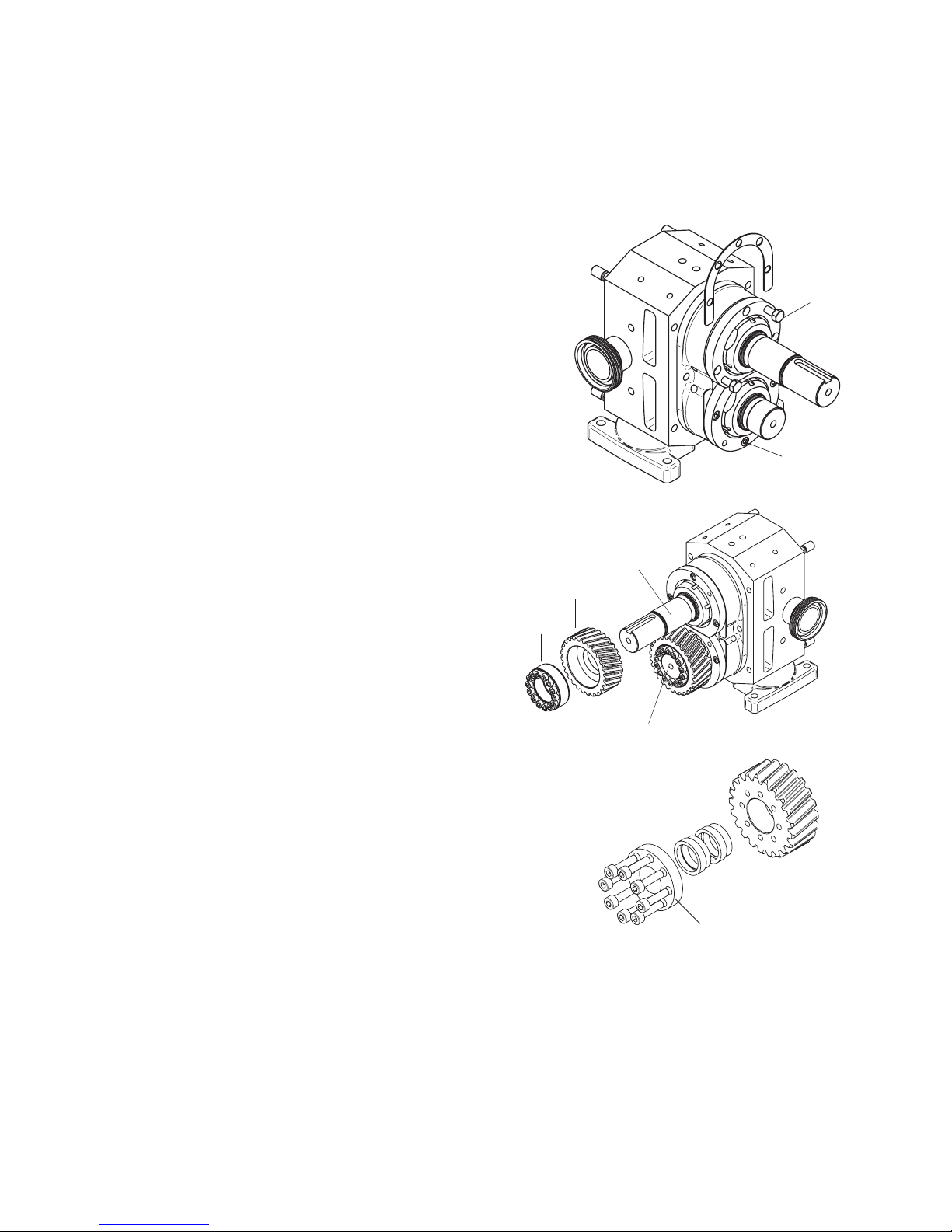
4.7.5 Assembly of gears
1. Place the gear (0190) with locking assembly (0652)
(locking elements (0651) for TW1) on
the lay shaft (0051).
2. TW1
Check if the screws of the locking elements are clean,
lubricate them with clean oil and fit them in place.
3. Place the gear (0190) with locking assembly (0652) (locking
elements (0651) for TW1) on the drive shaft (0050).
Use the torque wrench to tighten the bolts on the lay shaft
with the specified torque following the tightening sequence
shown below.
4. Check proper running of the gears (’’no heavy points’’) by
measuring axial run out of the gears (max 0.05 mm).
5. If the gears cannot be turned smoothly re-adjust the gears.
Bolt
Page 46
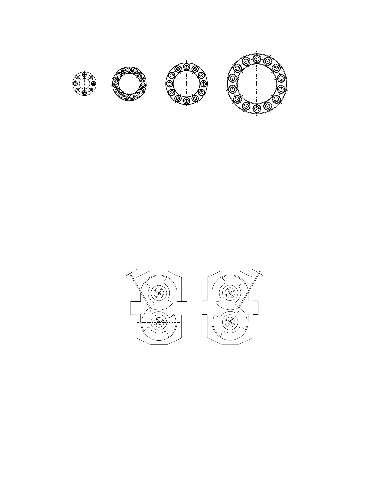
44 A.0500.301/314.C – IM-TW/10.00 GB (0401)
TW1 TW2 TW3
TW4
1
4
8
12
2
6
9
3
7
11
10
5
1
3
13
10
6
2
8
12
4
14
9
5
1
7
11
15
3
5
7
2
4
6
8
1
5
9
13
4
8
12
2
6
10
14
3
7
11
X
X
TW1 TW2 TW3 TW4
4.7.6 Synchronization of the rotors
4.7.6.1 Manual synchronization
1. Position the rotors by turning the drive shaft manually to the position shown in the
diagram.
Check the clearance between the rotors with a gage blade.
In both positions dimension X should be the same.
2. Place a block of soft material between the rotors to lock them against each other.
3. Tighten now the screws of the locking assembly/elements in the same way as
described for the lay shaft.
4. Check the clearance between the rotors, turn the drive shaft 180° and check the
clearance in this position also. In both positions dimension X should be the same.
5. Remove the retainers and rotors.
Pump Description Torque [Nm]
TW1 Allen screw DIN 912 M5x20 (12.9) 8.5
TW2 Allen screw DIN 912 M6x18 (12.9) 9
TW3 Allen screw DIN 912 M8x22 (12.9) 22
TW4 Allen screw DIN 912 M10x25 (12.9) 42
Page 47
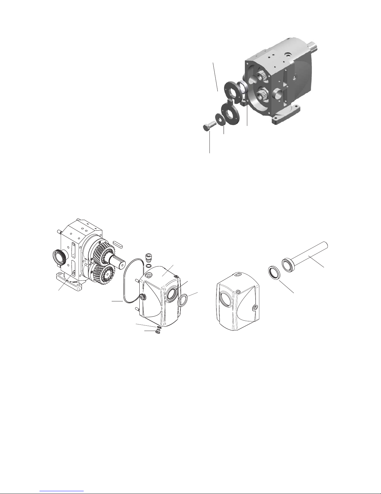
45
A.0500.301/314.C – IM-TW/10.00 GB (0401)
0880
0870
0875
0120
0181
0881
0455
0880
{
4.7.6.2 Synchronization with special tools
1. Position the shafts using the
synchronization tool.
2. Assemble the synchronization
tool as indicated on the figure,
so that the shafts are well
positioned.
3. Tighten the screws of the
locking assembly/elements in
the same way as described for
the lay shaft.
4.7.7 Assembly of end cover
1. Fit lip seal (0880) with Locktite in end cover (0120) and place O-ring (0181) on the
rotor case.
2. Put the end cover into position and tighten it with cap nuts (0455).
3. Fill the space between the lips of the V-seal (0881) with grease.
4. Fit the V-seal on the shaft by using the tool, for the right position; see table below.
Bush
Synchronization
tool
Ring
Tap bolt
Assembly tool for lip seal
Tool
Page 48
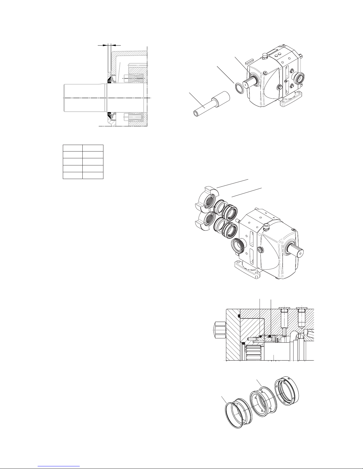
46 A.0500.301/314.C – IM-TW/10.00 GB (0401)
0083
0082
B
0881
0880
}
0082 0083
4.7.8 Assembly of seals
4.7.8.1 Single mechanical seal
1. Place the stationary part of the seal
in the rotor case. Ensure that the pin in
the rotor case fits into the groove in
the stationary part of the seal.
2. Put O-ring (0083) on the stationary
seal face. Place the stationary seal face
with O-ring into the rotor case. Ensure
that the pins in the stationary part of
the seal are fitting into the grooves in
the stationary seal face.
3. Put O-ring (0082) on rotating seal face.
Place the rotating seal face with O-ring
into the rotor.
Ensure that the pins in the rotor are
fitting into the grooves of the rotating
seal face.
Assembly tool for V-seal
Shaft position
Dimensions in mm
Rotor
Seal assembly
B
TW1 4
TW2 4.5
TW3 5.5
TW4 5.5
Tool
Page 49
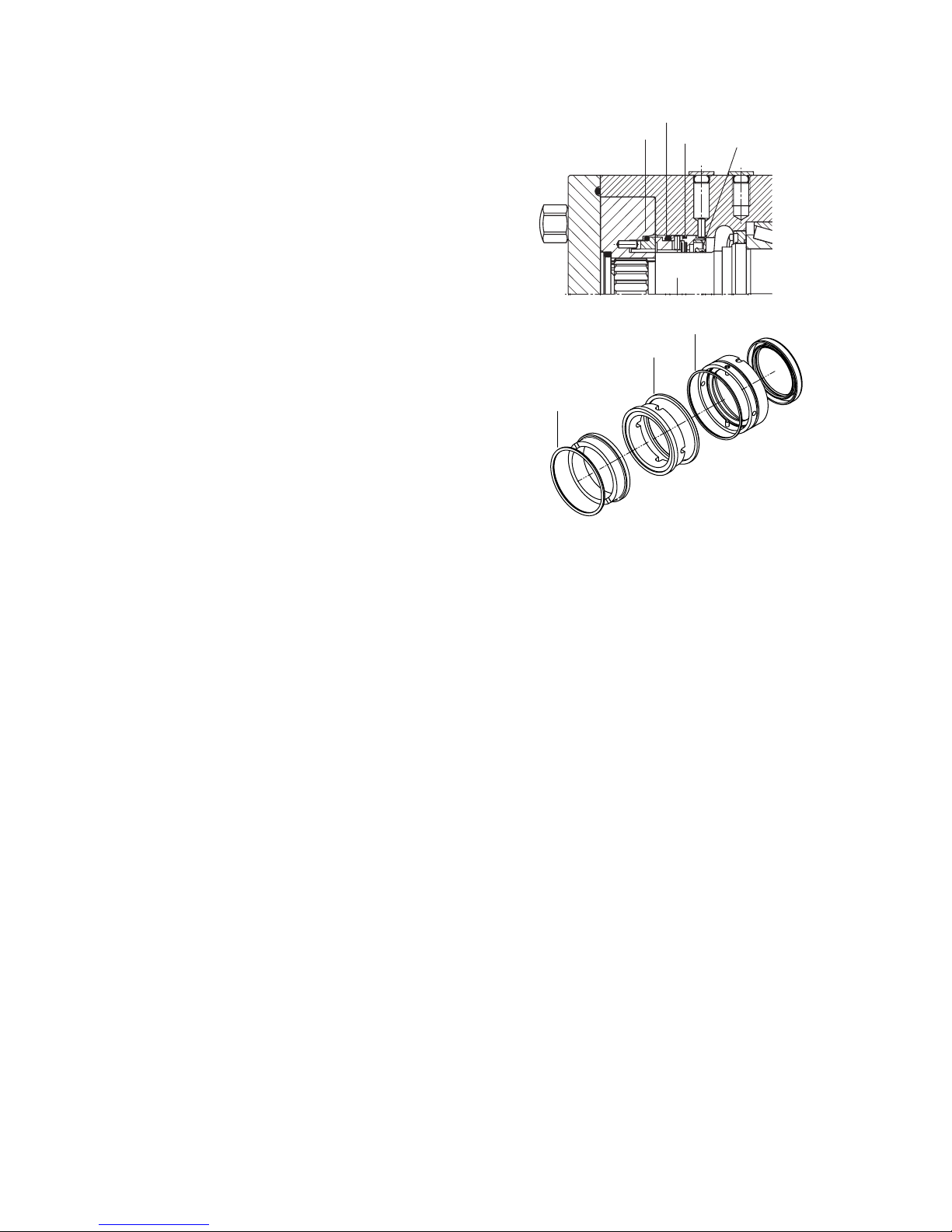
47
A.0500.301/314.C – IM-TW/10.00 GB (0401)
0082
0083
0085
0082
0083
0085
0890
4.7.8.2 Single mechanical seal with flushing
1. Fit lip seal (0890) and O-ring
(0085) in the stationary part of
the seal.
2. Place the stationary part of the
seal, O-ring and spring in the
rotor case.
Ensure that the pin in the rotor
case fits into the groove in the
stationary part of the seal.
3. Put O-ring (0083) on the
stationary seal face. Place the
stationary seal face with
O-ring into the rotor case.
Ensure that the pins in the
stationary part of the seal are
fitting into the grooves in the
stationary seal face.
4. Put O-ring (0082) on rotating
seal face. Place the rotating
seal face with O-ring into the
rotor.
Ensure that the pins in the rotor
are fitting into the grooves of
the rotating seal face.
Page 50
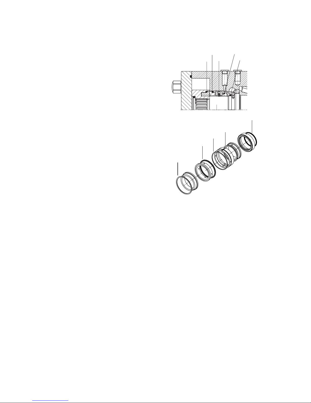
48 A.0500.301/314.C – IM-TW/10.00 GB (0401)
0082
0083
0085
0086
0087
0082
0083
0085
0086
0087
4.7.8.3 Double mechanical seal
1. Place O-ring (0087) on the
atmospheric side - seal face.
Push the atmospheric side rotating seal face with O-ring
over the shaft.
Ensure that the pins in the
shaft are fitting into the
grooves in the seal face.
2. Place O-ring (0085), O-ring
(0086) and atmospheric side stationary seal face into the
stationary part of the seal.
Place the stationary part of the
seal with O-rings and
atmospheric side seal face into
the rotor case.
3. Put O-ring (0083) on the
product side - stationary seal
face. Place the stationary seal
face with O-ring into the rotor
case.
Ensure that the pins in the
stationary part of the seal are
fitting into the grooves in the
stationary seal face.
4. Put O-ring (0082) on rotating
seal face. Place the rotating
seal face with O-ring into the
rotor.
Ensure that the pins in the
rotor are fitting into the
grooves of the rotating seal
face.
Page 51
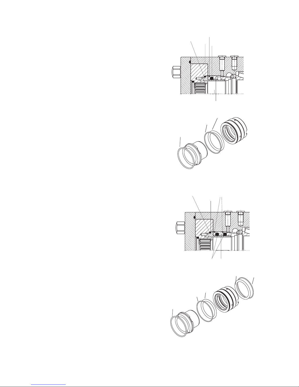
49
A.0500.301/314.C – IM-TW/10.00 GB (0401)
0082
0085
0183
0183
0085
0082
0085
0183
0097
0130
0082
0085
0183
0097
0130
0082
0085
0183
4.7.8.4 Single O-ring seal
1. Fit O-rings (0085) and (0183) in
support ring (0097). Place support
ring with O-rings into the rotor
case. Ensure that the pin in the
rotor case fits into the groove in
the support ring.
2. Place O-ring (0082) on the shaft
sleeve (0130). Place shaft sleeve
with O-ring into the rotor. Ensure
that the pins in the rotor are
fitting into the grooves of the
shaft sleeve.
3. Rotor and shaft sleeve should be
assembled together.
4.7.8.5 Double O-ring seal
1. Fit O-rings (0085) and (0183) in
support ring (0097). Place support
ring with O-rings into the rotor
case.
Ensure that the pin in the rotor
case fits into the groove in the
support ring.
2. Place O-ring (0082) on the shaft
sleeve (0130). Place shaft sleeve
with O-ring into the rotor. Ensure
that the pins in the rotor are
fitting into the grooves of the
shaft sleeve.
3. Rotor and shaft sleeve should be
assembled together.
Page 52
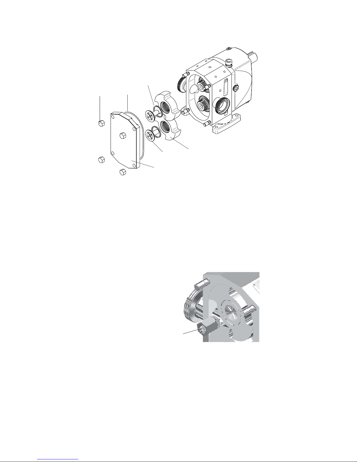
50 A.0500.301/314.C – IM-TW/10.00 GB (0401)
0450
0250
0801
0800
0020
0030
4.7.9 Assembly of rotors and pump cover
4.7.9.1 Assembly of rotors
1. Place the rotors (0020) on the shafts.
2. Place O-rings (0800) on the retainers (0250) and fasten the retainers.
See chapter 4.5 Tightening torque for nuts and screws.
3. Block the rotors against each other by putting a block of soft material between the
rotors.
4. Tighten the retainers clockwise with the specified torque, using the retainer tool.
See chapter 4.5 Tightening torque for nuts and screws.
5. Check all clearances.
4.7.9.2 Assembly of pump cover
1. Put the O-ring (0801) into the groove in the pump cover.
2. Place the pump cover on the rotor case. Be sure that O-ring (0801) stays in the
groove and is not squeezed between pump cover and rotor case.
3. Secure the pump cover with cap nuts (0450).
Retainer tool
Page 53
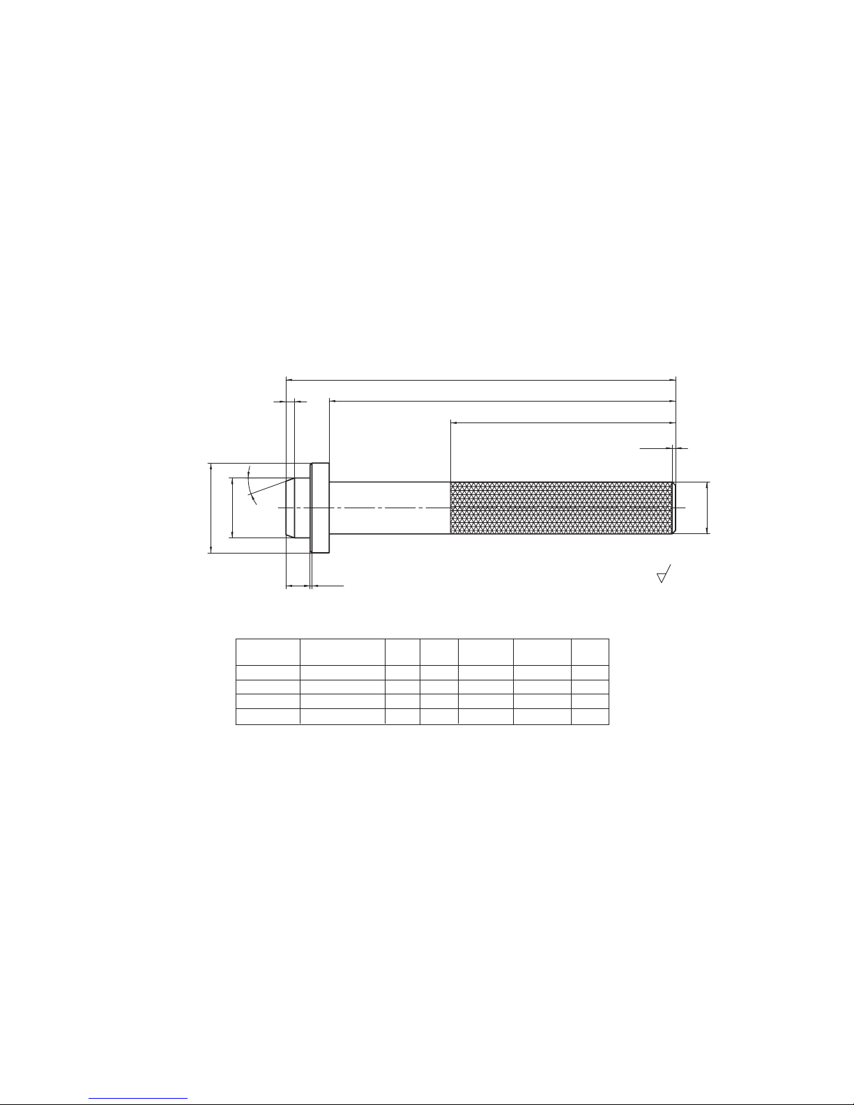
51
A.0500.301/314.C – IM-TW/10.00 GB (0401)
5
2
0
˚
B
A
130
3.2
E
1x45˚
Ø C ±0.2
Ø D
2x45˚
Ø 30
5.0 Special tools
5.1 General
There are a number of special tools available to facilitate assembling the pumps. By
using these tools the risk of damaging sealing elements is reduced and the time needed
for maintenance and/or repair will be shorter.
These tools can be ordered from Johnson Pump or produced in the own workshop. The
article numbers for ordering are indicated in the tables under each drawing/picture
together with the dimensions of the tool in question (if applicable).
5.2 Assembly tool for lip seals
Place: Rotor case front end
Purpose: For fitting the lip seal (0885) into the rotor case (see section 4.7.1.2)
Pump type Article number A B ØC ±0,2 ØD +0,1 E
0
TW1 3.94935.11 225 200 34.6 51.8 14
TW2 3.94936.11 235 200 55.6 79.8 17
TW3 3.94937.11 235 200 68 109.8 17
TW4 3.94938.11 290 250 99.6 149.8 20
All dimensions in mm
Page 54
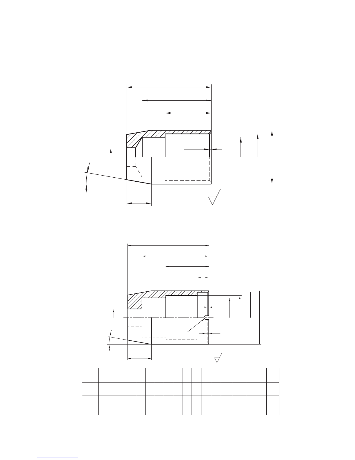
52 A.0500.301/314.C – IM-TW/10.00 GB (0401)
H
3.2
1
0
˚
B
A
C
D
Ø
J
Ø
K
±
0.1
Ø
L
Ø
I
Ø
M
±
0.1
R
F
G
Ex45˚
30
45
Ø
30 .2 ±0 .1
Ø
26
Ø
12
35 ±0.1
Ø
16
1
0
˚
55
3.2
1x45˚
5.3 Assembly sleeve for lip seals
Place: Rotor case front end
Purpose: For fitting the shaft/bearing assembly into the rotor case (see section 4.7.3)
Assembly sleeve TW2, TW3 and TW 4
All dimensions in mm
Assembly sleeve TW1
Type Article number A B C D E F G H Ø I Ø J ØK Ø L ØM
±0,1 ±0,1
TW1 3.94939.11
TW2 3.94940.11 85 70 45 12 1 2 2 25 18 41 46.2 53 56
TW3 3.94941.11 90 80 45 14 0.5 2 2 25 18 56 60.2 68 +0,2 71.2
-0,2
TW4 3.94942.11 125 108 55 15 1 2.5 2.5 30 22 75 85.2 91 100
Page 55
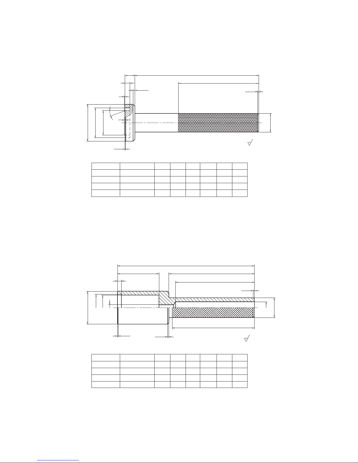
53
A.0500.301/314.C – IM-TW/10.00 GB (0401)
Ø D
30
Ø
130
3.2
Ø EAØ F
2
0
˚
2
200
B
1
C x45˚
1 x 45˚
2x45˚
3.2
M10
Ø
F
±
0.1
Ø
E
Ø
D
C
B
1x45
˚
125
2x45
˚
A
Ø
18
2x45˚
30
Ø
120
130
5.4 Assembly tool for lip seal
Place: Endcover rear end
Purpose: For fitting the radial lip seal (0880) into the end cover (see section 4.7.7)
5.5 Assembly tool for V-seal
Place: Endcover rear end
Purpose: For fitting the axial lip seal (0881) on the drive shaft (see section 4.7.7)
All dimensions in mm
All dimensions in mm
Pump type Article number A B C Ø D Ø E Ø F
TW1 3.94943.11 15 7 2 38.3 28.5 20.5
TW2 3.94944.11 16 8 3 59.5 48.5 39.5
TW3 3.94945.11 20 10 5 69.5 60.5 48.5
TW4 3.94946.11 25 12 5 97.5 89.5 74.5
Pump type Article number A B C Ø D Ø E ØF ±0,1
TW1 3.94947.11 177 32 6 30 20.5 19.2
TW2 3.94948.11 208 63 6 50 40.5 38.2
TW3 3.94949.11 235 90 10 60 50.5 48.2
TW4 3.94950.11 295 150 10 85 75.5 70.2
Page 56
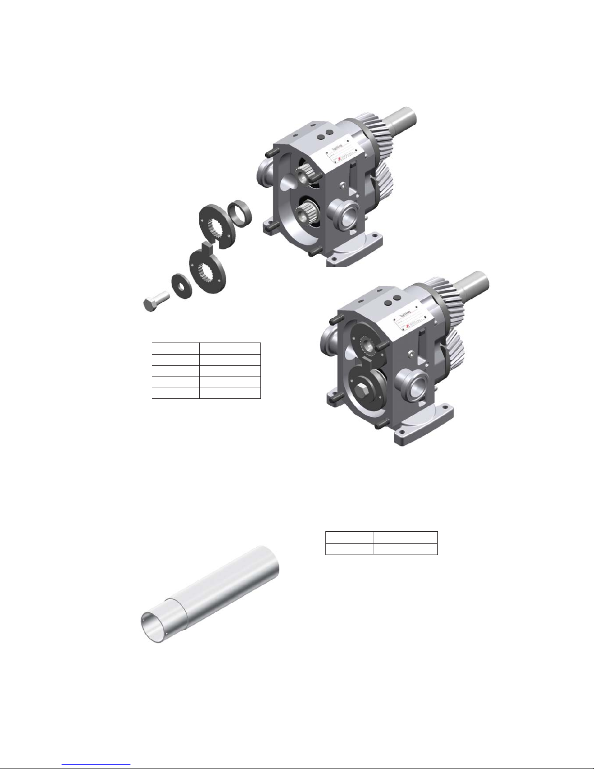
54 A.0500.301/314.C – IM-TW/10.00 GB (0401)
5.6 Tool kit for synchronization of the pump shafts
Purpose: To adjust the position of the shafts against each other (see section 4.7.6.2)
5.7 Tool for disassembly O-ring seal TW1
Purpose: To disassemble the support ring from the rotor case
(see sections 4.6.2.4 and 4.6.2.5)
All dimensions in mm
Pump Type Article number
TW1 3.01983.01
TW2 3.01983.11
TW3 3.01983.21
TW4 3.01983.31
Pump Type Article number
TW1 3.94998.11
Page 57

Johnson Pump Group
Parent Company
SWEDEN
Johnson Pump AB
Tel. +46 (0)19 21 83 00
Fax +46 (0)19 27 23 30
National Sales
Organisations
AUSTRALIA
Johnson Pump (Australia) Pty. Ltd.
Tel. +61 (0)7 3899 9933
Fax +61 (0)7 3899 8574
BELGIUM
Johnson Pump N.V./S.A.
Belgium:
Tel. +32 (0)2 422 15 50
Fax +32 (0)2 422 15 59
the Netherlands:
Tel. +31 (0)592 34 28 33
Fax +31 (0)592 40 93 51
DENMARK
Johnson Pumper A/S
Tel. +45 43 52 24 00
Fax +45 43 52 15 77
Business Units
BELGIUM
Johnson Pump Brussels N.V.
Tel. +32 (0)53 60 27 15
Fax +32 (0)53 60 27 01
INDIA
Johnson Pump (India) Ltd.
Tel. +91 (0)79 287 03 11
Fax +91 (0)79 287 25 22
NETHERLANDS
Johnson Pump Water B.V.
Tel. +31 (0)592 37 67 67
Fax +31 (0)592 37 67 60
SWEDEN
Johnson Pump AB
Tel. +46 (0)19 21 83 00
Fax +46 (0)19 27 23 72
USA
Johnson Pumps of America, Inc.
Tel. +1 847 671 7867
Fax +1 847 671 7909
FINLAND
Johnson Pump Oy
Tel. +358 (0)9 348 3800
Fax +358 (0)9 348 38495
FRANCE
Johnson Pompes
Tel. +33 (0)1 39 20 50 00
Fax +33 (0)1 39 56 54 22
GERMANY
Johnson Pumpen GmbH
Tel. +49 (0)5731 480 80
Fax +49 (0)5731 414 00
ITALY
Johnson Pump Italiana S.r.l.
Tel. +39 039 604 14 63
Fax +39 039 604 90 97
NETHERLANDS
Centrifugal Pumps.
Positive Displacement Pumps,
contact Belgium.
Johnson Pump B.V.
Tel. +31 (0)592 37 67 67
Fax +31 (0)592 37 67 60
Johnson Pump Horticulture
Tel. +31 (0)174 51 84 10
Fax +31 (0)174 51 84 44
NORWAY
Johnson Pump A/S
Tel. +47 22 74 08 40
Fax +47 22 28 03 30
SPAIN
Johnson Pump España, S.L.
Tel. +34 972 58 08 01
Fax +34 972 58 08 03
Sales Office:
Madrid: Tel. +34 91 888 79 22
SWEDEN
Johnson Pump Svenska
Tel. +46 (0)19 21 83 70
Fax +46 (0)19 27 23 18
SWITZERLAND
Johnson Pumpen AG
Tel. +41 (0)43 477 71 22
Fax +41 (0)43 477 71 20
UNITED KINGDOM
JP Pumps Ltd.
Tel. +44 (0)1293 55 34 95
Fax +44 (0)1293 52 46 35
Northern Regional Office:
Bradford: Tel. +44 (0)1274 74 22 47
Fax +44 (0)1274 74 22 28
www.johnson-pump.com
Nastagatan 19. P.O. Box 1436, SE-701 14 Örebro, Sweden. Tel. +46 (0)19 21 83 70. Fax +46 (0)19 27 23 30. E-mail: [email protected].
Johnson Pump AB
 Loading...