

Page 1
1
IB-103/03 (9902)
Instruction Manual
Submersible
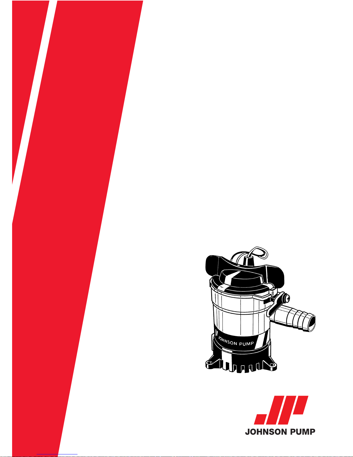
bilge pumps
Cartridge L-Series,
L450, L550, L650, L750
Page 2

2
Garantie 1 an
Garantía 1 año
Garanzia 1 anno
Garanti 1 år
Warranty 1 year
Garantie 1 Jahr
INDEX - INDICE
Svenska .................................................................................... 3
English ..................................................................................... 6
Deutsch .................................................................................... 9
Français.................................................................................. 12
Español .................................................................................. 15
Italiano ................................................................................... 18
Page 3
3
Svenska
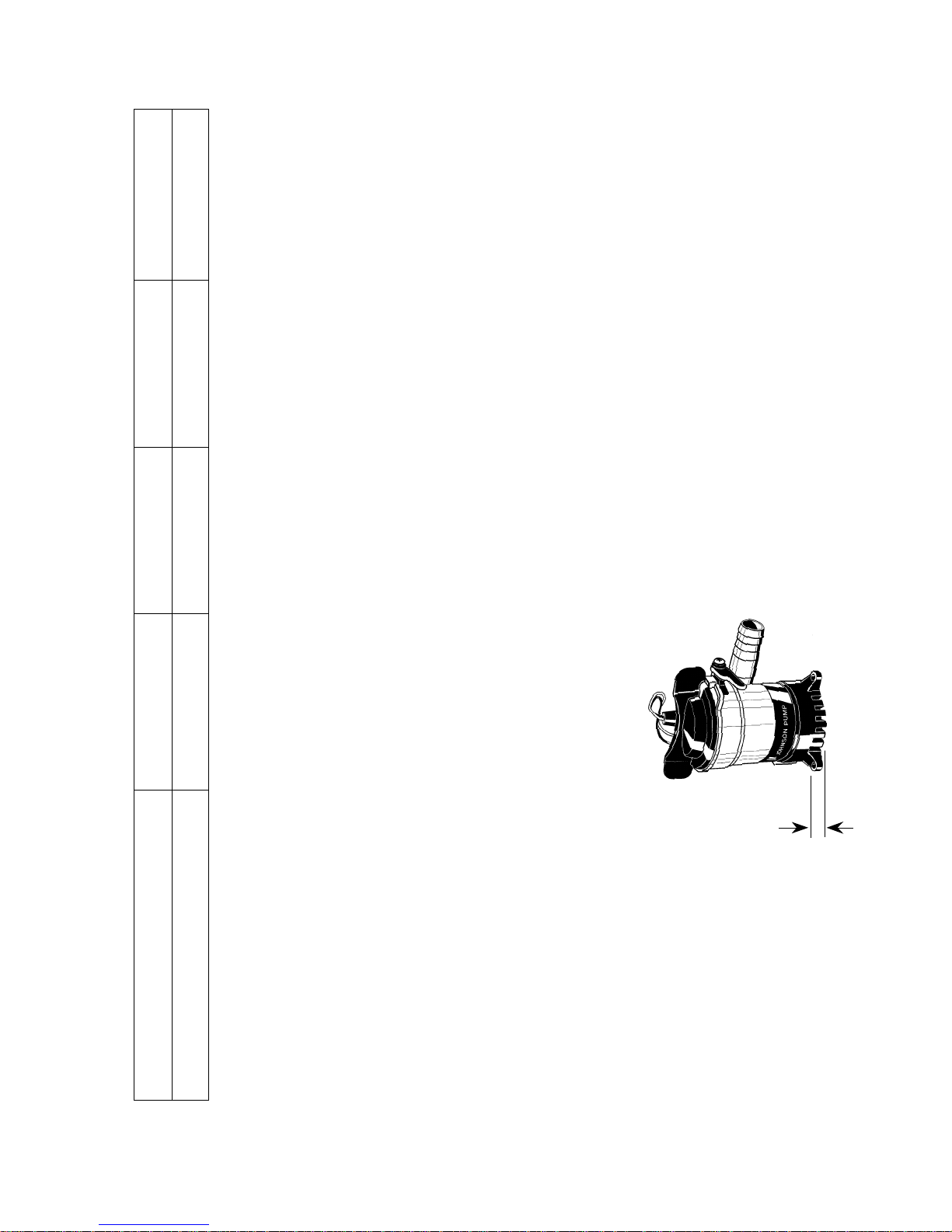
• Placera pumpen vid
lägsta punkten
• För längre livslängd,
kör inte pumpen torr
Teknisk beskrivning
L450 L550 L650 L750
Slanganslutning 3/4" 3/4" 3/4" 1,1/8"
Kapacitet, fritt utlopp (13,6 V) 49 l/min/778 GPH 56 l/min/884 GPH 61 l/min/972 GPH 73 l/min /1 150 GPH
Kapacitet, lyfthöjd 1 m (13,6 V) 38 l/min/601 GPH 45 l/min/713 GPH 53 l/min/844 GPH 60 l/min /952 GPH
Spänning 12 V DC 12 V DC 12 V DC 12 V DC
Strömförbrukning 2,5 A 3 A 3,2 A 3 A
Säkring 3 A 5 A 5 A 5 A
Höjd 112 mm 112 mm 112 mm 112 mm
Max dia 70 mm 70 mm 70 mm 70 mm
Vikt 0,27 kg 0,27 kg 0,27 kg 0,32 kg
Pumphus Termoplast Termoplast Termoplast Termoplast
Axeltätning Läpptätning Läpptätning Läpptätning Läpptätning
Ledningsarea 0,75 mm
2
0,75 mm
2
0,75 mm
2
0,75 mm
2
Lägsta sugnivå
Mått "A"
L450 –8 mm
L550 – 8 mm
L650 – 8 mm
L750 –8 mm
Modellspecifikation
Pumptyp L450 – 12 V L550 – 12 V L650 – 12 V L750 – 12 V
Art nr 32-1450-01 32-1550-01 32-1650-01 32-1750-01
A
Page 4

4
Svenska
INSTALLATION
Följ anvisningarna noggrant för
att uppnå maximal effekt.
1. Placera pumpen vid lägsta
punkten.
2. Välj en plats där vattnet ska
pumpas överbord - så högt
som möjligt över vattenlinjen
och så nära pumpen som
möjligt. Använd en 19 mm
(3/4") bordgenomföring
(L750 – 28 mm (1,1/8").
3. Anslut en 19 mm (3/4")
(L750 – 28 mm (1,1/8")
bränslesäker slang från
pumpens utlopp till bordgenomföringen. Undvik
skarpa veck och öglor. Om
nödvändigt, fäst slangen.
Obs! För att förhindra luftfickor är det viktigt att
slangen inte riktas nedåt vid
utloppet. Slangen ska hela
tiden riktas uppåt.
3. Ta inte bort mer än nödvän-
digt av plasten runt kabeln.
Alla elanslutningar måste
alltid sitta över högsta
vattennivån. Kabelskarvarna
ska tätas med ett marint
tätningsmedel för att förhindra oxidation.
Montering/demontering av
motor-/impellerenheten
Se sid 21
1. Lyft låshaken och vrid de två
vingarna moturs och lyft ur
enheten.
2. Innan enheten återplaceras,
kontrollera att tätningen sitter
på plats. Smörj tätningen med
mineral- eller vegetabilisk
olja. Placera enheten så att
den passar in i skårorna på
pumphuset. Pressa ned och
vrid vingarna medurs. Prova
om enheten är rätt placerad
genom att vrida vingarna
moturs utan att lyfta låshaken.
Enheten ska då sitta fast
ordentligt.
Elektrisk installation
1. Anslut den bruna kabeln till
batteriets pluspool (+).
2. Anslut den svarta kabeln till
batteriets minuspol (-).
Page 5
5
Svenska
Installation Johnson Pump
dränkbara länspump/
nivåströmbrytare AS888/
strömbrytarpanel
Se sid 22
Installera alltid AS888, strömbrytarpanel och säkringar
mellan batteriets pluspol (+)
och pumpens plusanslutning
(+) (brun kabel).
Pumpens minusanslutning (-)
(svart kabel) ansluts till
batteriets minuspol (-) direkt.
Säkringsstorlek väljs efter
pumpens säkringsspecifikation.
TILLBEHÖR
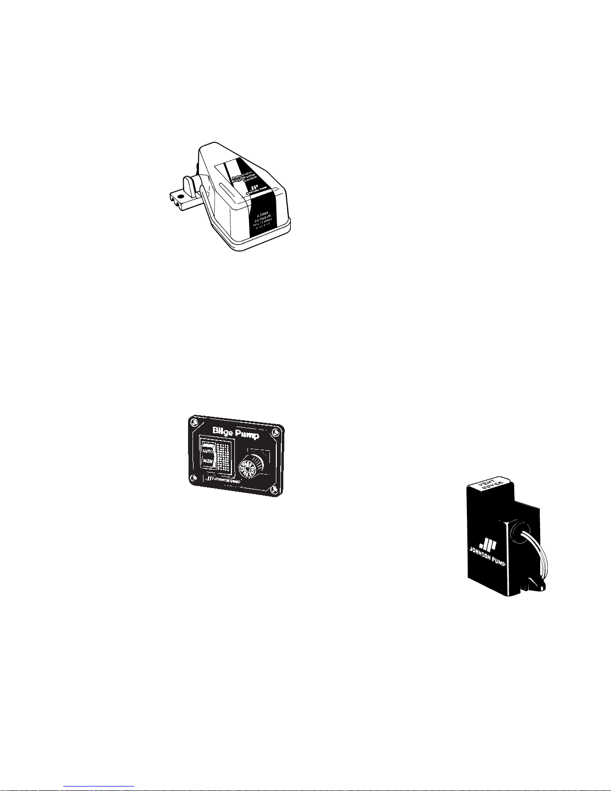
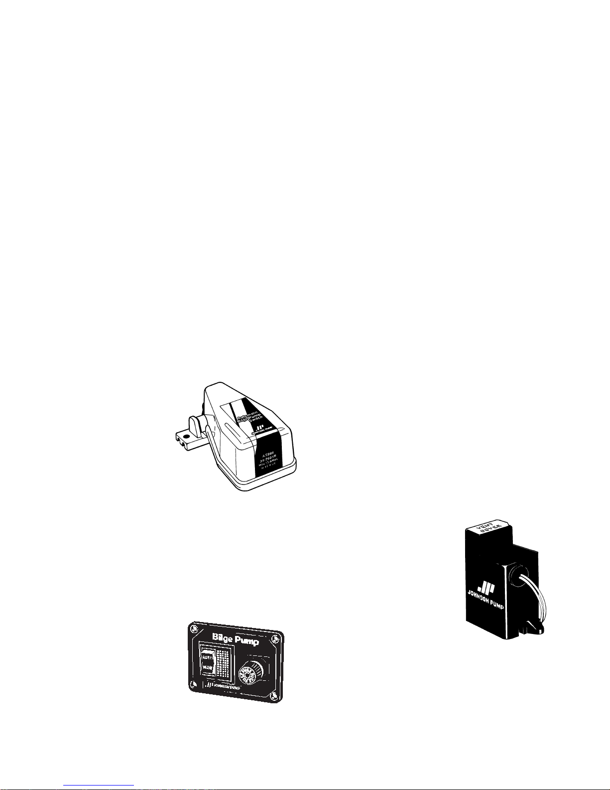
Automatisk nivåströmbrytare AS888
Art nr
34-888
Den automatiska nivåströmbytaren
skyddar eldrivna
pumpar och ger en helautomatisk drift. Nivåströmbrytaren är
gjord av korrosionsbeständiga
material.
Strömbrytarpanel
12 eller 24 V
Art nr
12 V – 34-1224
24 V – 34-1225
Panelen tillsammans med nivåströmbrytaren AS888 ger den
absolut bästa installationen i
din båt.
Elektronisk nivåströmbrytare
Art nr
34-1900 B – 12 V
34-1900 B – 24 V
Den elektroniska
strömbrytaren är
likadan som den
som sitter på
Cartridge Duo. Den passar till
alla pumpar i Johnson Pumps
L-serie.
Page 6
6
English
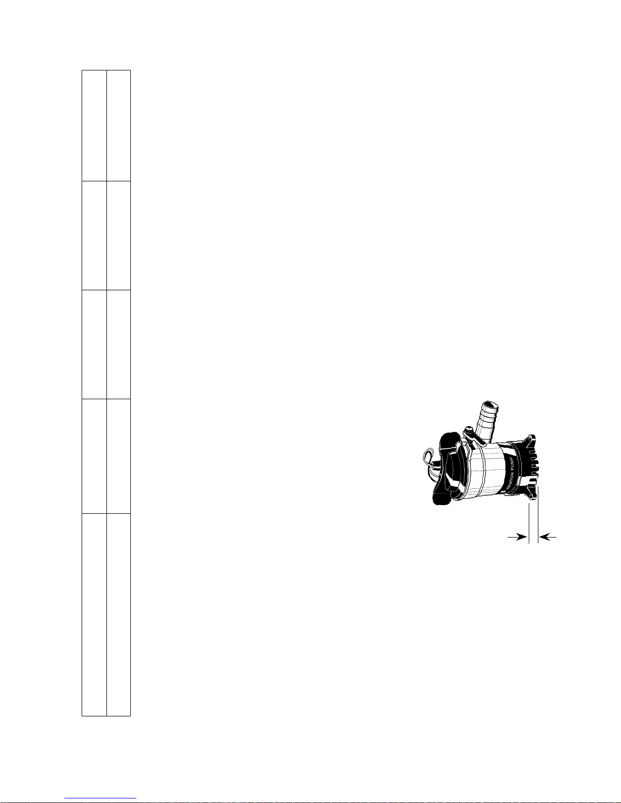
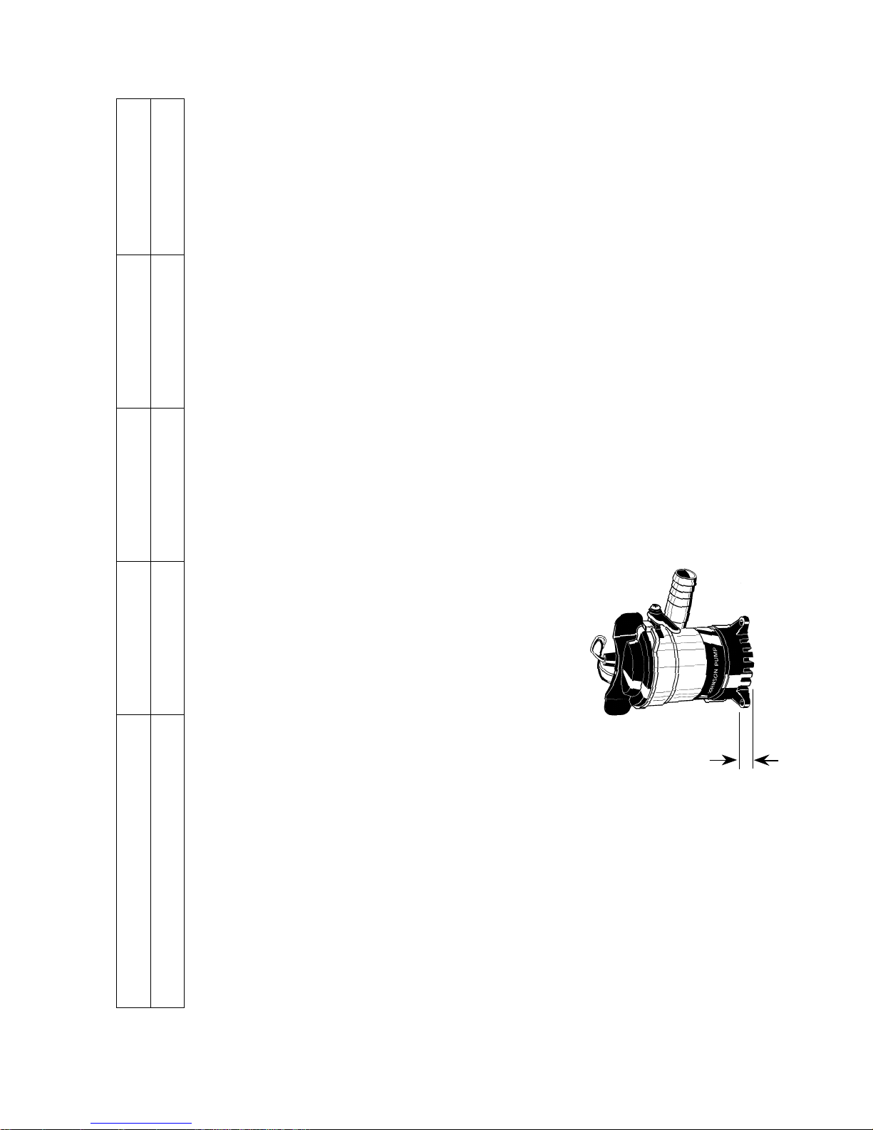
• Mount in the lowest
point of the bilge
• For longer pump life,
do not run dry
Lowest level for suction
Measure "A"
L450 – 8 mm
L550 – 8 mm
L650 – 8 mm
L750 – 8 mm
Type designation
Pump type L450 – 12 V L550 – 12 V L650 – 12 V L750 – 12 V
Art no 32-1450-01 32-1550-01 32-1650-01 32-1750-01
A
Design features
L450 L550 L650 L750
Hose size 3/4" 3/4" 3/4" 1.1/8"
Capacity, straight (13.6 V) 49 l/min/778 GPH 56 l/min/884 GPH 61 l/min/972 GPH 73 l/min /1,150 GPH
Capacity, 1 m head (13.6 V) 38 l/min/601 GPH 45 l/min/713 GPH 53 l/min/844 GPH 60 l/min /952 GPH
Voltage 12 V DC 12 V DC 12 V DC 12 V DC
Amperage 2,5 A 3 A 3.2 A 3 A
Fuse size 3 A 5 A 5 A 5 A
Height 112 mm 112 mm 112 mm 112 mm
Max dia 70 mm 70 mm 70 mm 70 mm
Weight 0.27 kg 0.27 kg 0.27 kg 0.32 kg
Body Thermoplastic Thermoplastic Thermoplastic Thermoplastic
Shaft seal Lip seal Lip seal Lip seal Lip seal
Wire size 0.75 mm
2
0.75 mm
2
0.75 mm
2
0.75 mm
2
Page 7

7
INSTALLATION
Please follow the installation
instructions carefully to assure
maximum efficiency in your
bilge pump operation.
1. Mount the pump in the lowest
point of the bilge.
2. Select a point where the bilge
water is to be pumped overboard as high as possible
above the water line and at
the shortest distance from the
pump. Install a 3/4" thru-hull
fitting (L750 – 1.1/8").
3. Fasten a 3/4" (L750 – 1.1/8")
fuel resistant hose from the
pump outlet to the thru-hull
fitting. Avoid sharp bends or
loops. Support the hose if
necessary.
Note: In order to prevent air
lock is important that the
hose not be allowed to dip
below the pump outlet. The
hose should be constantly
rising.
3. Do not cut back insulation
more than necessary. Insulation or cable sheathings have
to be removed in such a way
that they end well above the
highest bilge water level. The
wire connections should be
sealed with a marine sealant
to prevent wire corrosion.
English
Electrical installation
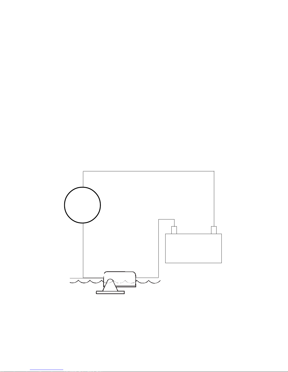
1. Connect the brown wire to
the positive (+) terminal of
the battery.
2. Connect the black wire to
the negative (-) terminal of
the battery.
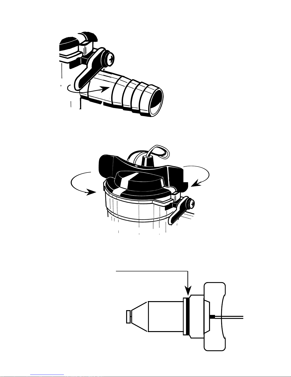
To remove or replace power
cartridge
See page 21
1. Lift tab and rotate the two
fins in a counter clockwise
direction and lift out.
2. To reinstall, first make sure
that the seal is properly
located. Coat the seal with
a light film of vegetable oil
or mineral oil, then align the
two cams on either side of
the power cartridge with the
two slots in the outer housing.
Press down and twist in a
clockwise rotation. To ensure
that the power cartridge is
properly located, twist tins in
a counter clock-wise direction
without lifting tab. Cartridge
should stay in place.
Page 8
8
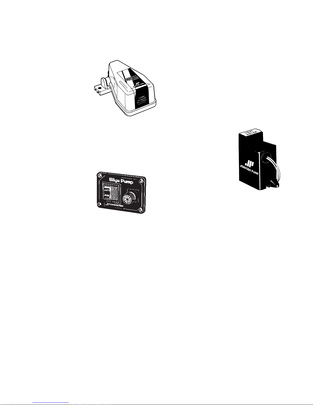
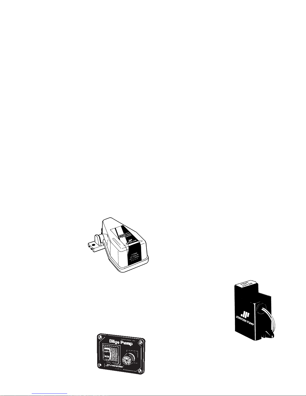
ACCESSORIES
Automatic
Switch AS888
Part No. 34-888
The automatic
switch AS888
protects electrically
operated pumps and
gives fully automatic
operation. The AS888 is made
of corrosion resistant materials.
Panel 12 or 24 V
Part No.
12 V – 34-1224
24 V – 34-1225
The panel combined with automatic
switch AS888 is an excellent
installation for your boat.
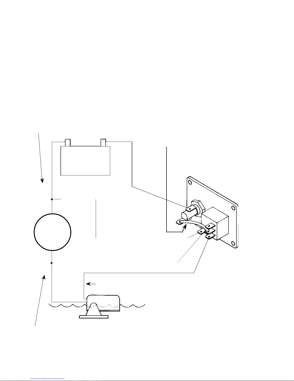
The negative (-) connection
(black wire) of the pump to be
connected directly to the
negative (-) terminal of the
battery. Fuse size applies to
pump specification.
English
Installation Johnson Pump
submersible bilge pump/
automatic switch AS888/
Panel
See page 22
Always install switch AS888,
panel and fuses between the
positive (+) terminal of the
battery and the positive (+)
connection of the pump
(brown wire).
Electronic Float Switch
Part No.
34-1900 B – 12 V
34-1900 B – 24 V
The electronic float
switch is the same
switch as on
Cartridge Duo. As
a separate accessory it is
possible to attach the switch to
all pumps in the Johnson Pump
L-serie.
Page 9
9
Deutsch
• An der niedrigsten Stelle in
der Bilge montieren
• Nicht trocken laufen lassen,
verringert die Lebensdauer
der Pumpe
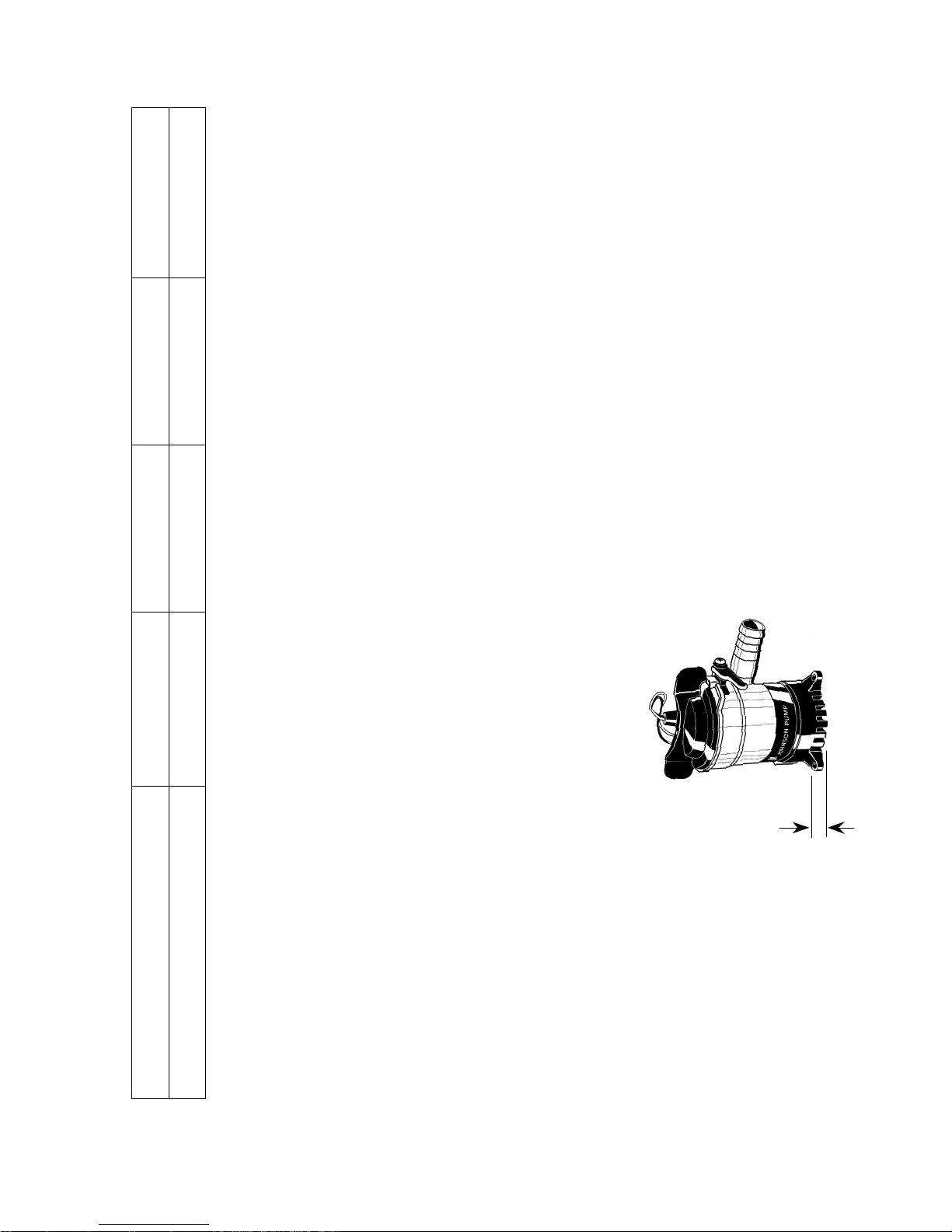
Niedrigste Ansaughöhe
Abmessung "A"
L450 –8 mm
L550 –8 mm
L650 –8 mm
L750 –8 mm
Modellvarianten
Typ L450 – 12 V L550 – 12 V L650 – 12 V L750 – 12 V
Artikel Nr. 32-1450-01 32-1550-01 32-1650-01 32-1750-01
A
Technische Beschreibung
L450 L550 L650 L750
Schlauchdurchm. 3/4" 3/4" 3/4" 1,1/8"
Leistung, bei direktem Auslauf (13,6 V) 49 l/min/778 GPH 56 l/min/884 GPH 61 l/min/972 GPH 73 l/min /1.150 GPH
Leistung, 1 m Förderhöhe (13,6 V) 38 l/min/601 GPH 45 l/min/713 GPH 53 l/min/844 GPH 60 l/min/952 GPH
Spannung 12 V DC 12 V DC 12 V DC 12 V DC
Stromaufnahme 2,5 A 3 A 3,2 A 3 A
Sicherung 3 A 5 A 5 A 5 A
Höhe 112 mm 112 mm 112 mm 112 mm
Durchmesser 70 mm 70 mm 70 mm 70 mm
Gewicht 0,27 kg 0,27 kg 0,27 kg 0,32 kg
Gehäuse Thermoplastik Thermoplastik Thermoplastik Thermoplastik
Wellendichtung Lippendichtung Lippendichtung Lippendichtung Lippendichtung
Kabelquerschnitt 0,75 mm
2
0,75 mm
2
0,75 mm
2
0,75 mm
2
Page 10

10
EINBAU
Bitte befolgen Sie diese Anweisungen, nur dann kann garantiert werden, daß die Pumpe
einwandfrei und mit voller
Leistung arbeitet.
1. Die Pumpe an der niedrig-
sten Stelle im Bilgenraum
montieren.
2. Wählen Sie eine günstige
Stelle, wo das Bilgenwasser leicht überboard gepumpt
werden kann, so hoch wie
möglich über der Wasserlinie und den kürzesten
Abstand zur Pumpe. Zu
diesem Zweck soll ein 3/4
(L750 – 1,1/8") Schottdurchgang angebracht werden.
3. Befestigen Sie eine brenn-
stoffeste, 3/4" (L750 –
1,1/8") Schlauchverbindung
an dem Pumpenauslaß, das
andere Endezum 3/4"
Schottdurchgang. Der
Schlauch sollte eine
konstante Steigung haben.
Elektrische Anlagen
1. Den braunen Leiter zur
positiven (+) Klemme der
Batterie legen.
2. Den schwarzen Leiter zur
negativen (-) Klemme der
Batterie legen.
3. Die Isolierung so wenig wie
möglich zurückschneiden
und alle Anschlüsse wohl
über der Wasserfläche
halten. Die elektrischen
Verbindungen müssen auf
sicherem Abstand über dem
Hochwasserstand im Bilgenboden angebracht werden.
Als Korrosionsschutz sollen
die Leiter mit einer wasserfesten Dichtung geschützt
werden. Isolierungen oder
Kabelummantelungen
müssen so zurückgeschnitten
werden, daß die Isolierung
oder Ummantelung in einem
sicheren Abstand über dem
Hochwasserstand endet.
Um die Treibeinheit zu
entfernen oder ersätzen
Siehe Seite 21
1. Die Zunge heben und die
zwei Flügeln gege Uhrzeigersinn drehen und aufheben.
2. Um wieder zu montieren,
sich vergewissern dass die
Dichtung richtig gelegen ist.
Die Dichtung mit einem
dünnen schicht vegetabilischer oder Mineralöl ein-
Deutsch
Page 11
11
Deutsch
schmieren, dann die zwei
Kämme auf beiden Seite der
Treibeinheit mit der zwei
Ausspahrungen in der
änssere Gehäuse einrichten.
Herunterdrücken und im
Uhrzeigersinn umdrehen.
Um sich zu vergewissern
dass die Treibeinheit richtig
eingesetzt ist, die zwei
Flügeln gegen Uhrzeigersinn drehen, ohne die Zunge
zu heben. Die Treibeinheit
sollte sich nicht bewegen.
Johnson Pump
Tauchbilgenpumpe/Niveauschalter AS888/Schalttafel
Siehe Seite 22
Den Niveauschalter AS888, die
Schalttafel und die Sicherung
immer zwischen der positiven
(+) Klemme der Batterie und
der positiven (+) Verbindung
an der
Pumpe (brauner Leiter)
anschließen.
Der negative (-) Leiter (schwarz)
der Pumpe wird direkt an die
negative (-) Klemme der
Batterie gelegt. Der Nennstrom
der Sicherung bezieht sich auf
die Pumpenspezifikation.
Schalttafel 12 oder 24 V
Art. Nr.
12 V – 34-1224
24 V – 34-1225
Die Schalttafel,
zusammen mit
dem Niveauschalter
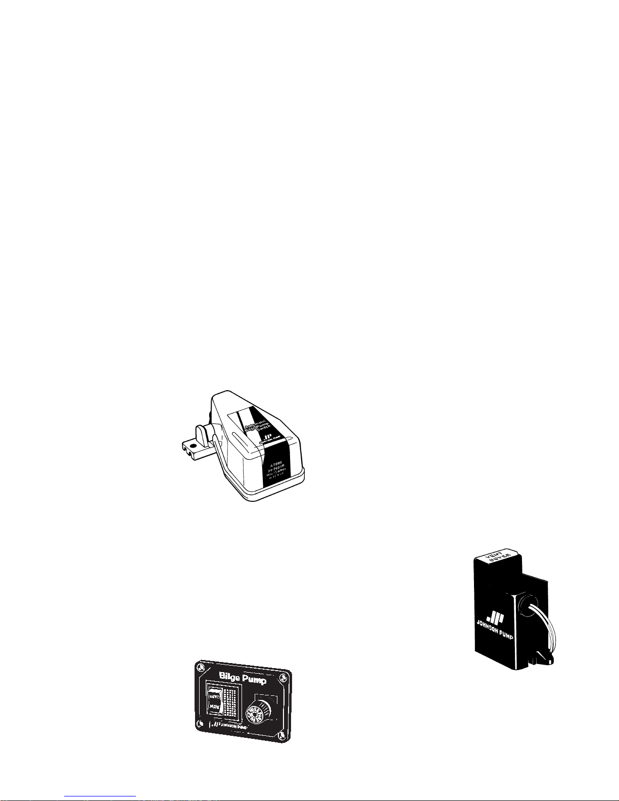
ZUBEHÖR
Automatischer
Niveauschalter
AS888
Art. Nr. 34-888
AS888 schützt
elektrische Pumpen
und bietet vollautomatischen
Betrieb. Der AS888 Schalter
ist aus korrosionsfesten
Materialien hergestellt.
Electronik-Schwimmerschalter
Art. Nr.
34-1900 B – 12 V
34-1900 B – 24 V
Der elektronische
Schwimmerschalter
ist der gleiche, wie
an der Duo Patronenpumpe. Als separates Zubehör
ist es möglich, diesen an alle
Johnson Pump Bilge-Pumpen
der L-Serie zu befestigen.
AS888 ist eine vorzügliche
Kombination für Ihr Boot.
Page 12
12
Français
• Installer la pompe au point
le plus bas de la cale
• Pour une plus longue durée
de vie de la pompe, ne pas la
faire fonctionner à vide
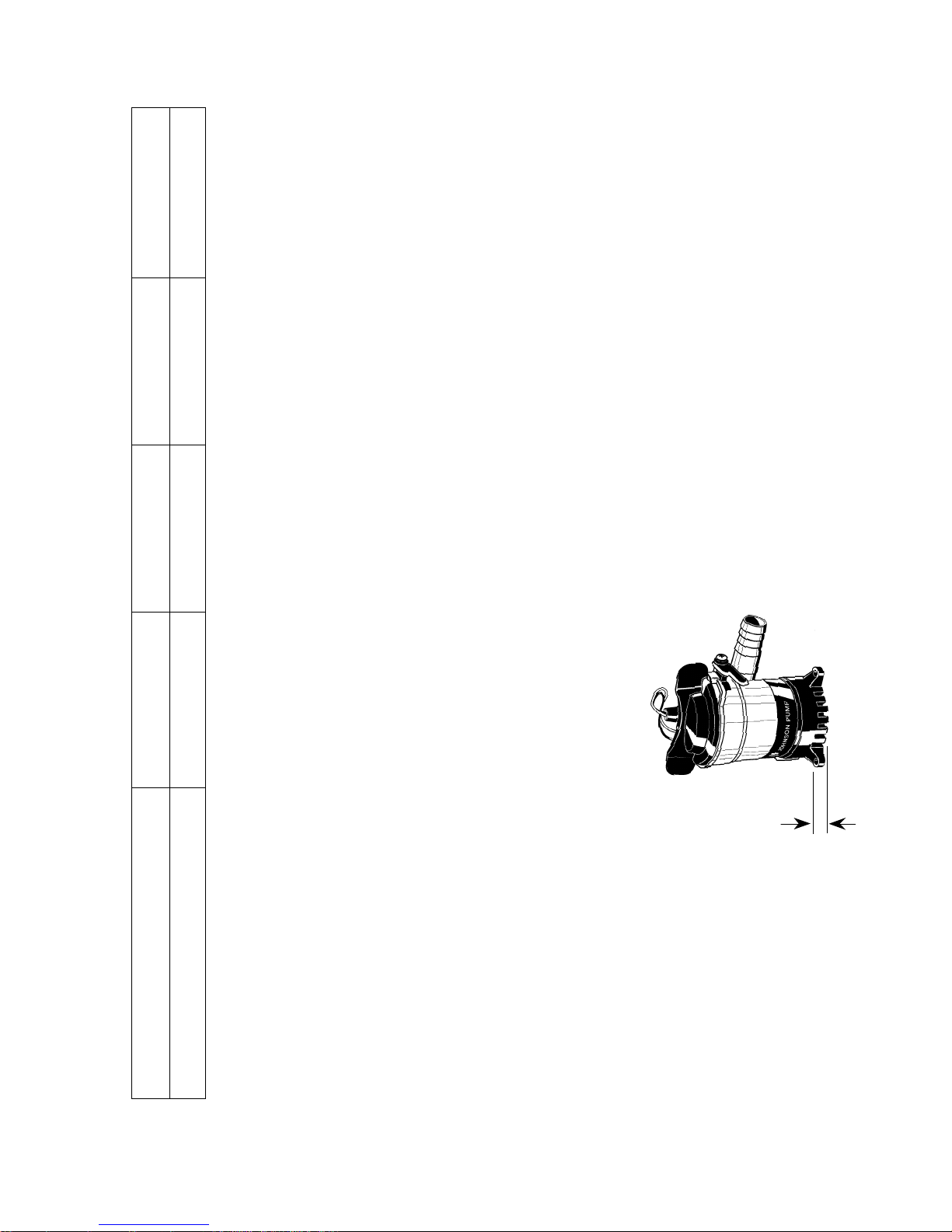
Plus bas niveau pour la succion
Mesure "A"
L450 –8 mm
L550 –8 mm
L650 –8 mm
L750 –8 mm
Spécifications du modèle
Modèle L450 – 12 V L550 – 12 V L650 – 12 V L750 – 12 V
Référence 32-1450-01 32-1550-01 32-1650-01 32-1750-01
A
Caractéristiques techniques
L450 L550 L650 L750
Diam. de tuyau 19 mm 19 mm 19 mm 28 mm
Débit, refoulement libre (13,6 V) 49 l/min/778 GPH 56 l/min/884 GPH 61 l/min/972 GPH 73 l/min/1 150 GPH
Débit, refoulement à 1 m (13,6 V) 38 l/min/601 GPH 45 l/min/713 GPH 53 l/min/844 GPH 60 l/min/952 GPH
Voltage 12 V DC 12 V DC 12 V DC 12 V DC
Intensité 2,5 A 3 A 3,2 A 3 A
Fusible 3 A 5 A 5 A 5 A
Hauteur 112 mm 112 mm 112 mm 112 mm
Diam. maxi 70 mm 70 mm 70 mm 70 mm
Poids 0,27 kg 0,27 kg 0,27 kg 0,32 kg
Corps Thermoplastique Thermoplastique Thermoplastique Thermoplastique
Etanchéité Joint à lèvres Joint à lèvres Joint à lèvres Joint à lèvres
Section de câbles 0,75 mm
2
0,75 mm
2
0,75 mm
2
0,75 mm
2
Page 13

13
Français
INSTALLATION
Suivre méticuleusement les
instructions ci-dessous afin
d’obtenir un rendement optimum.
1. Monter la pompe au point
le plus bas de la cale.
2. Choisir un endroit par lequel
les eaux de cale seront
pompées et évacuées aussi
haut que possible au-dessus
de la ligne d’eau et le plus
près possible de la pompe.
Installer un raccord fileté de
19 mm (L750 – 28 mm) à
travers la coque.
3. Monter un tuyau résistant à
l’essence de 19 mm (L750 –
28 mm) entre la sortie de la
pompe et le raccord fileté
traversant la coque. Eviter les
plis et les boucles. Fixer le
tuyau si nécessaire.
Important: Afin d’éviter les
poches d’air, il est important
de s’assurer que la sortie du
tuyau ne soit pas dirigée vers
le bas, mais toujours vers le
haut.
Installation electrique
1. Relier le fil marron à la borne
positive (+) de la batterie.
2. Relier le fil noir à la borne
negative (-) de la batterie.
3. Ne pas enlever la pelicule
isolatrice plus que nècessaire.
Tous les branchements
électriques doivent être placés
au-dessus du niveau le plus
haut des eaux de cale. Toutes
les connexions et les bornes
doivent être isolées à l’aide
d’un matériau etanche pour
éviter toute corrosion. Le
dénudage des câbles doit être
fait de façon à ce que l’isolant
ou le revêtement extérieur
du câble soit bien au-dessus
du niveau le plus haut des
eaux de cale.
Pour enlever ou remplacer
l'ensemble moteur
Voir page 21
1. Soulever la languette et
tourner les deux oreilles dans
le sens de rotation inverse à
celui des aiguilles d'une montre.
2. Pour remonter, s'assurer
d'abord que le joint est bien
en place. Enduire le joint
d'une mince couche d'huile
végétale ou minérale, et
aligner ensuite les deux
tenons des deux côtés de
l'ensemble moteur, avec les
Page 14
14
Français
ACCESSOIRES
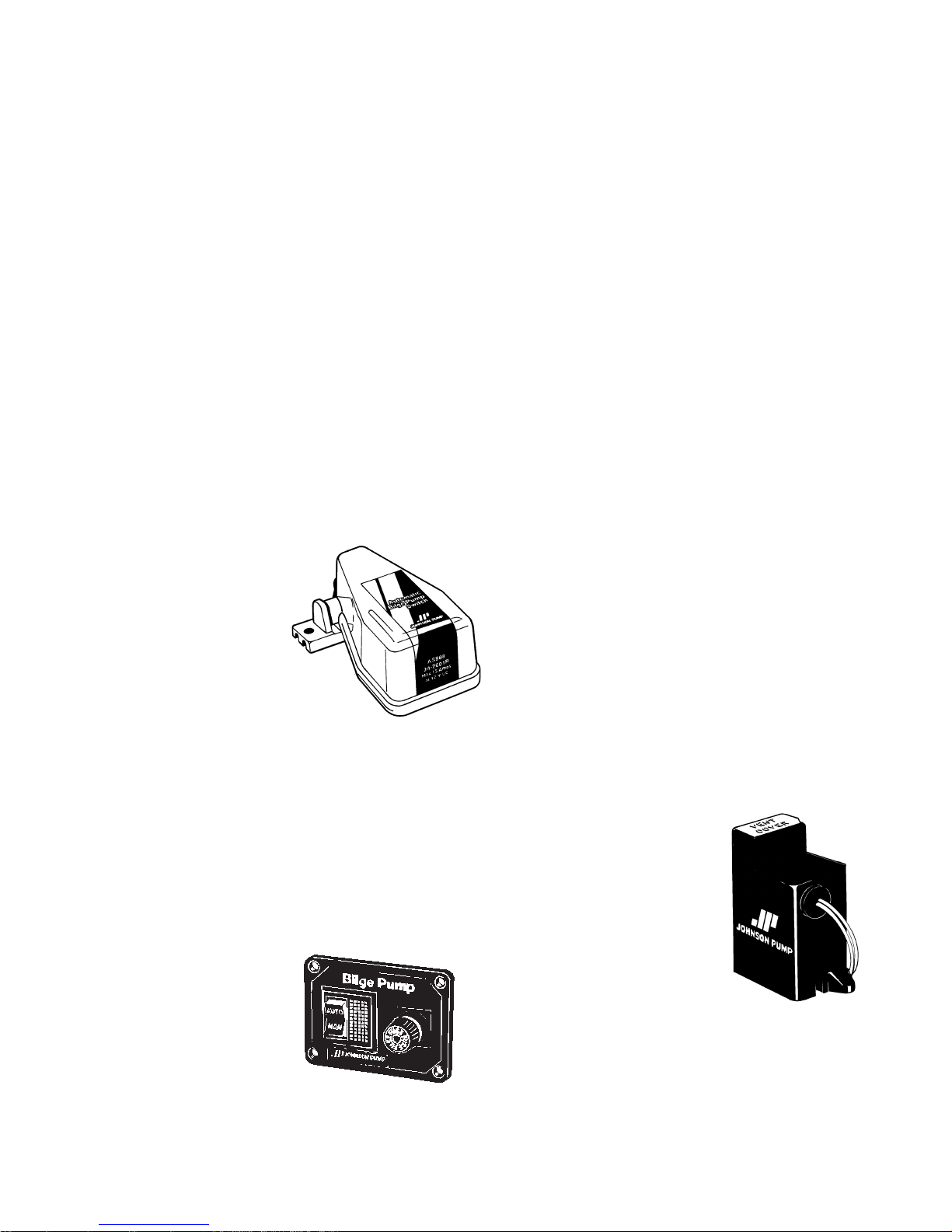
Interrupteur
automatique à
flotteur AS888
Ref. No. 34-888
AS888 protège les
pompes fonctionnant à
l’électricité et offre un mode
de fonctionnement entièrement
automatique. Le AS888 est
composé de matériaux
résistants à la corrosion.
Tableau de commande
12 ou 24 V
Ref. No.
12 V – 34-1224
24 V – 34-1225
Avec un tableau
de commande pour l’interrupteur AS888 vous aurez une
échancrures correspondantes
du corps exterieur. Presser et
tourner dans le sens de rotation des aiguilles d'une
montre. Pour s'assurer que
l'ensemble moteur est bien
en place, tourner les oreilles
dans le sens de rotation
inverse à celui des aiguilles
d'une montre, sans soulever
la languette. L'ensemble
moteur doit rester en place.
Pompe de cale submersible
Johnson Pump/Interrupteur
à flotteur AS888/Tableau de
commande
Voir page 22
Toujours brancher l’interrupteur
à flotteur AS888, le tableau de
commande et les fusibles entre
la borne positive (+) de la
batterie et la borne positive (+)
de la pompe (fil marron).
La borne négative (-) de la
pompe doit être directement
connectée à la borne négative (-)
de la batterie. Le choix des
fusibles se fait en fonction des
spécifications de la pompe.
installation parfaite pour votre
bateau.
Contacteur de niveau
électronique
Ref. No.
34-1900 B – 12 V
34-1900 B – 24 V
Le contacteur de
niveau électronique
est le même que sur
les pompes à cartouche
Duo. Il est fourni en tant
qu´accessoire séparé et il est
possible de l´accrocher sur les
pompes Johnson Pump series L.
Page 15
15
Español
• Montar en el punto más bajo
de la sentina
• Para prolongar vida útil,
no hacer funcíonar en seco
Altura mínima de aspiración
Medida "A"
L450 –8 mm
L550 – 8 mm
L650 –8 mm
L750 – 8 mm
Modelo
Tipo L450 – 12 V L550 – 12 V L650 – 12 V L750 – 12 V
Pieza No 32-1450-01 32-1550-01 32-1650-01 32-1750-01
A
Características técnias
L450 L550 L650 L750
Manga 3/4" 3/4" 3/4" 1,1/8"
Capacidad, directo (13,6 V) 49 l/min/778 GPH 56 l/min/884 GPH 61 l/min/972 GPH 73 l/min /1.150 GPH
Capacidad, altura 1 m (13,6 V) 38 l/min/601 GPH 45 l/min/713 GPH 53 l/min/844 GPH 60 l/min/952 GPH
Tensión 12 V DC 12 V DC 12 V DC 12 V DC
Amperaje 2,5 A 3 A 3,2 A 3 A
Fusible 3 A 5 A 5 A 5 A
Altura 112 mm 112 mm 112 mm 112 mm
Diá. max. 70 mm 70 mm 70 mm 70 mm
Peso 0,27 kg 0,27 kg 0,27 kg 0,32 kg
Material Thermoplástico Thermoplástico Thermoplástico Thermoplástico
Junta eje Junta de labio Junta de labio Junta de labio Junta de labio
Conductor 0,75 mm
2
0,75 mm
2
0,75 mm
2
0,75 mm
2
Page 16

16
INSTALACIÓN
Se recomienda observar
estrictamente estas instrucciones de instalación para
asegurar la mayor eficacia de
la bomba de sentina.
1. Montar la bomba en el
punto más bajo de la sentina.
2. Elegir un punto por el que
el agua de sentina se vaya
a bombear fuera que esté
lo más alejado posible de
la línea de flotación y a la
menor distancia de la bomba.
Instalar un accesorio de 3/4"
(L750 – 1,1/8") atravesando
el casco.
3. Fijar una manga de 3/4"
(L750 – 1,1/8") resistente al
petróleo de la salida de la
bomba al accesorio que
atraviesa el casco. Evitar
cocas y lazos. Si fuera
necesario, apoyar la manga.
Observación: para evitar
la entrada de aire, es importante no dejar que la manga
caiga por debajo de la salida
de la bomba. La manga debe
presentar una elevación
constante.
Equipo eléctrico
1. Conectar el conductor
castaño al borne positivo
(+) de la batería.
2. Conectar el conductor
negro al borne negativo (-)
de la batería.
3. No quitar el aislamiento
mas que necesario. Todo el
cableado debe quedar por
encima del nivel màs alto de
agua. Las conexiones deben
sellarse con un compuesto
para aplicaciones marinas a
fin de evitar la corrosión de
los cables. El material
aislante o camisa del cable
debe separarse de tal modo
que el aislante o camisa
termine bien por encima del
nivel más alto de agua de la
sentina.
Para quitar o substituir la
unidad motriz
Ver página 21
1. Levantar la lengüeta y girar
las dos orejas en sentido
contrario a lo de la rotación
de las agujas del reloj, y
sacar la unidad motriz.
2. Para montrar de nuevo,
asegurarse que la junta
estea en su sitio. Untar la
junta de una capa menuda
de aceite vegetal o mineral,
Español
Page 17
17
Español
y luego alinear los dos cames
de los dos lados de la unidad
motriz con las dos muescas
del cuerpo exterior. Apretar
y girar en el sentido de rotación de las agujas del reloj.
Para asegurarse que la unidad
motriz estea bien en su sitio,
girar las orejas en el sentido
contrário a lo de la rotación
de las agujas del reloj sin
levantar la lengüeta.
La unidad motriz suele
quedarse en su sitio.
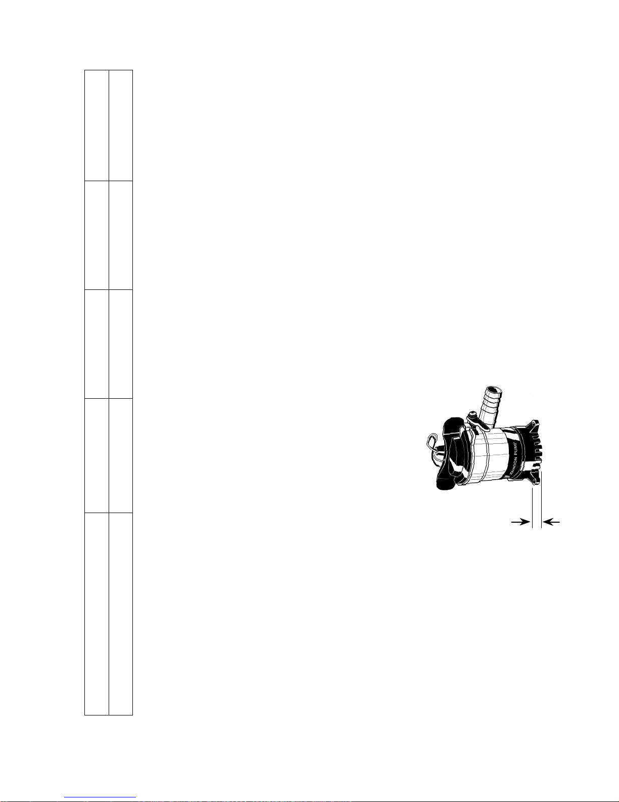
Tablero 12 o 24 V
Pieza No.
12 V – 34-1224
24 V – 34-1225
El tablero junto
ACCESORIOS
Interruptor flotante
automático AS888
Pieza No.
34-888
El interruptor
flotante automático AS888
protege bombas
eléctricas aportando
una operación completamente
automática. El AS888 está
hecho de materiales resistentes
a la corrosión.
Bomba submergible de
sentina Johnson Pump/
Interruptor flotante AS888/
Tablero
Ver página 22
Instalar siempre el interruptor
flotante AS888, el tablero y
los fusibles entre el borne
positivo (+) de la batería y el
terminal positivo (+) de la
bomba (conductor marrón).
El terminal negativo (-) de la
bomba debe ser conectado
directamente al borne negativo (-) de la batería. La capacídad del fusible depende de
la bomba.
con el interruptor AS888
constituyen un equipamiento
excelente para su embarcación.
Interruptor electrónico de
achique
Pieza No.
34-1900 B – 12 V
34-1900 B – 24 V
Es el mismo
interruptor que
llevan las bombas
"Cartridge Duo". Como
accesorio es posible conectarlo
a todas las bombas sumergibles
Johnson Pump serie L.
Page 18
18
Italiano
• Montare nel punto più basso
della sentina
• Per prolungare la vita della
pompa, evitare le operazioni
a secco
Livello più basso per aspirazione
Misura "A"
L450 –8 mm
L550 – 8 mm
L650 –8 mm
L750 – 8 mm
Specifica del tipo
Tipo L450 – 12 V L550 – 12 V L650 – 12 V L750 – 12 V
Art. No. 32-1450-01 32-1550-01 32-1650-01 32-1750-01
A
Caratteristiche tecniche
L450 L550 L650 L750
Sezione tubo 3/4" 3/4" 3/4" 1,1/8"
Portata massima (13,6 V) 49 l/min/778 GPH 56 l/min/884 GPH 61 l/min/972 GPH 73 l/min/1.150 GPH
Portata a 1 mt di prevalenza (13,6 V) 38 l/min/601 GPH 45 l/min/713 GPH 53 l/min/844 GPH 60 l/min/952 GPH
Voltaggio 12 V DC 12 V DC 12 V DC 12 V DC
Amperaggio 2,5 A 3 A 3,2 A 3 A
Capacità fusibile 3 A 5 A 5 A 5 A
Altezza 112 mm 112 mm 112 mm 112 mm
Diametro max. 70 mm 70 mm 70 mm 70 mm
Peso 0,27 kg 0,27 kg 0,27 kg 0,32 kg
Corpo Termoplastico Thermoplastico Termoplastico Termoplastico
Guarnizione albero Tipo "Corteco" Tipo "Corteco" Tipo "Corteco" Tipo "Corteco"
Dimensione cavo 0,75 mm
2
0,75 mm
2
0,75 mm
2
0,75 mm
2
Page 19

19
Italiano
INSTALLAZIONE
Si prega di seguire con attenzione le istruzioni di montaggio
per garantire la massima
efficacia di funzionamento
alla vostra pompa di sentina.
1. Montare la pompa nel punto
più basso della sentina.
2. Scegliere il punto da cui
l’acqua di sentina deve essere
pompata fuori bordo, il più
alto possibile rispetto alla
linea d’acqua ed alla minima
distanza dalla pompa.
Installare un attacco di 3/4"
(L750 – 1,1/8") attraverso la
carena.
3. Collegare un tubo di 3/4"
(L750 – 1,1/8") resistente ai
carburanti dalla mandata della
pompa all’attacco a carena.
Evitare curve brusche o
occhielli. Se necssario,
supportare il tubo.
Nota: per prevenire bolle
d’aria é importante che il tubo
non si immerga al di sotto
della mandata della pompa.
Il tubo dovrebbe essere
costantemente sollevato.
Installatione elettrica
1. Collegare il cavo elettrico
marrone al terminale positivo
(+) della batteria.
2. Collegare il cavo elettrico
nero al terminale negativo (-)
della batteria.
3. Non rimuovere il isolamento
più che necessario. Tutti i
collegamenti elettrici devono
essere posti al di sopra del
livello più alto dell’acqua.
I collegamenti ed i cavi
devono essere sigillati con
un sigillante marino per
prevenire la corrosione.
L’isolamento o la guaina del
cavo devono essere rimossi
in modo tale che l’isolamento
o la guaina terminino ben al
di sopra del livello più alto
dell’acqua di sentina.
Per rimuovere o sostiture
l'unità motrice
Vedi página 21
1. Levare la linguetta e girare
le due ali in senso antiorario
e sollevare l'unità motrice.
2. Per rimontare, in primo
luogo assicurarsi che la
guarnizione sai in luogo.
Ungere la guarnizione con
una pellicola di oleo vegetale o minerale, dopo
Page 20
20
ACCESSORI
Interruttore Automatico
galleggiante AS888
Art. Nr. 34-888
AS888 protegge
le pompe a
funzionamento
elettrico ed automatizza completamente le operazioni.
AS888 é prodotto usando
materiali resistenti alla
corrosione.
Pannello 12 o 24 V
Art. Nr.
12 V – 34-1224
24 V – 34-1225
Il pannello
combinato con
l’interruttore AS888
garantisce una eccellente
alineare le due came da tutti
e due i lati dell'unità motrice
con le due tacche del corpo
esteriore. Opprimere e
girare in senso orario. Per
assicurarsi che l'unità
motrice sai in luogo, girare
le ali in senso antiorario
sensa sollevare la linguetta.
L'unità motrice doverà
rimanere in luogo.
Pompa di sentina sommersa/
Interruttore galleggiante
AS888/ Pannello
Vedi página 22
Installare sempre l’interruttore
galleggiante AS888, il pannello
ed i fusibili tra il terminale
positivo (+) della batteria ed il
collegamento positivo (+) della
pompa (cavo marrone).
Il collegamento negativo (-)
(cavo nero) della pompa deve
essere collegato direttamente al
terminale negativo (-) della
batteria. La capacità del
fusibile é determinata dalla
specifica della pompa.
Italiano
installazione per la vostra
barca.
Interruttore elettronico
di livello
Art. Nr.
34-1900 B – 12 V
34-1900 B – 24 V
Questo interruttore
elettronico di
livello è lo stesso che
viene montato sulle pompe
di sentina Duo. Può essere
montato su tutte le pompe
Johnson Pump serie L come
accessorio separato.
Page 21
21
Lyft låshaken
Lift tab
Die Zunge heben
Soulever la languette
Levantar la lengüeta
Levare la linguetta
Montera
Reinstall
Montieren
Remonter
Montrar
Rimontare
Demontera
Remove
Entfernen
Enlever
Quitar
Rimuovere
Tätning
Seal
Dichtung
Joint
Junta
Guarnizione
Page 22
22
Elektrisk intsallation med Johnson Pump panel
Electrical installation with Johnson Pump Panel
Elektrischer Anschluss mit Johnson Pump Schalttafel
Schéma de raccordement avec le tableau de commande Johnson Pump
Instalación eléctrica con panel Johnson Pump
Schema collegamento elettrico con pannello di controllo Johnson Pump
Johnson Pump Automatic Switch AS888
1. Panel
Panel
Schalttafel
Tableau de commande
Tablero
Pannello
Obs: Denna kabel är redan ansluten
Note: This cable is already connected
Wichtig: Kabel ist bereits verbunden
Important: Ce câble est déjà connecté
Advertencia: Este cable ya está conectado
Nota Bene: Questo cavo é già collegato
Marron
Marrón
Brun
Brown
Braun Marrone
4
+
–
–
+
6
3
Batteri • DC supply
DC-Versorgung
Batterie • Bateria
1
2
2. Länspump
Bilge pump
Bilgenpumpe
Pompe de cale
Bomba de sentina
Pompa di sentina
(-) svart pumpkabel
(-) black pump lead
(-) schwarzer Pumpeleiter
(-) fil noir de la pompe
(-) conductor bomba negro
(-) pompa cavo nero
(+) brun pumpkabel
(+) brown pump lead
(+) brauner Pumpeleiter
(+) fil marron de la pompe
(+) conductor bomba marrón
(+) pompa cavo marrone
Page 23
23
–
Elektrisk intsallation utan panel
Electrical installation without panel
Elektrischer Anschluss ohne Schalttafel
Schéma de raccordement sans tableau de commande
Instalación eléctrica sin panel
+
1. Länspump
Bilge pump
Bilgenpumpe
Pompe de cale
Bomba de sentina
Pompa di sentina
(-) svart pumpkabel
(-) black pump lead
(-) schwarzer Pumpeleiter
(-) fil noir de la pompe
(-) conductor bomba negro
(-) pompa cavo nero
(+) brun pumpkabel
(+) brown pump lead
(+) brauner Pumpeleiter
(+) fil marron de la pompe
(+) conductor bomba marrón
(+) pompa cavo marrone
1
+
–
Johnson Pump Automatic Switch AS888
Batteri • DC supply
DC-Versorgung
Batterie • Bateria
Page 24

24
Johnson Pump Marine
P.O. Box 1436, SE-701 14 Örebro, Sweden. Tel +46 (19) 21 83 00. Fax +46 (19) 27 23 72.
[email protected] / www.johnson-pump.com
Part of Johnson Pump AB
 Loading...