

Page 1
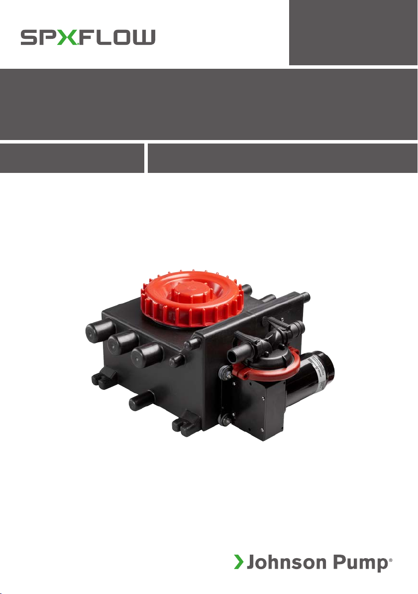
Grey Water Tank
WITH ULTIMA SWITCH, 12/24 V DC
INSTR UCTION MANUAL
IB-122 R05 (01/2016)
READ AND UN DERSTAND THI S MANUAL PRIOR TO OPERATING OR SERVI CING THIS
ORIGINAL I NSTRUCTION S/TRANSLATION OF ORIG INAL INSTR UCTIONS
PRODUCT
Page 2

INDEX INDICE
Svenska ..................................................................................................................... 3
English ......................................................................................................................4
Deutsch .....................................................................................................................5
Français .....................................................................................................................6
Español ......................................................................................................................7
Italiano .......................................................................................................................8
Besök www.johnson-pump.com för mer information om vår världsomspännande organisation, våra godkännanden, certifieringar och lokala representanter. SPX
FLOW, Inc. förbehåller sig rätten att ändra design och material utan föregående avisering. Designelement, konstruktionsmaterial och dimensioner som beskrivs i
denna bulletin gäller endast som information och skall alltid bekräftas skriftligt för att vara gällande.
For more information about our worldwide locations, approvals, certifications, and local representatives, please visit www.johnson-pump.com. SPX FLOW, Inc.
reserves the right to incorporate our latest design and material changes without notice or obligation. Design features, materials of construction and dimensional
data, as described in this bulletin, are provided for your information only and should not be relied upon unless confirmed in writing.
Für weitere Informationen über unsere weltweiten Standorte, Zulassungen, Zertifizierungen und unsere Vertreter vor Ort, besuchen Sie bitte unsere Webseite:
www.johnson-pump.com. Die SPX FLOW, Inc. behält sich das Recht vor, die neuesten Konstruktions- und Werkstoffänderungen ohne vorherige Ankündigung und
ohne Verpflichtung hierzu einfließen zu lassen. Konstruktive Ausgestaltungen, Werkstoffe sowie Maßangaben, wie sie in dieser Mitteilung beschrieben sind, sind nur
zur Information. Alle Angaben sind unverbindlich, es sei denn, sie wurden schriftlich bestätigt.
Pour plus d’information sur nos succursales internationales, nos approbations, nos certifications et nos représentants locaux, veuillez consulter notre site Internet
au www.johnson-pump.com. SPX FLOW, Inc. se réserve le droit d’incorporer nos plus récents concepts ainsi que tout autre modification importante sans préavis
ou obligation. Les éléments décoratifs, matériaux de construction et les données dimensionnelles, tels qu’énoncés dans ce communiqué, sont fournis pour votre
information seulement et ne doivent pas être considérés comme officiels à moins d’avis contraire par écrit.
Para más información sobre nuestras oficinas a nivel mundial, aprobaciones, certificaciones y representantes locales, por favor visite www.johnson-pump.com. SPX
FLOW, Inc. se reserva el derecho de incorporar nuestro diseño más reciente y cambios materiales sin necesidad de notificación previa u obligación de ningún tipo.
Características de diseño, materiales de construcción y dimensiones, tal y como están descritas en este boletín, son proporcionadas sólo con fines informativos y
no deben ser usados como referencia a menos que sean confirmados por escrito.
Per ottenere maggiori informazioni sulle nostre sedi nel mondo, autorizzazioni, certificazioni, e rappresentanti locali, potete visitare il sito www.johnson-pump.com.
La SPX FLOW, Inc. si riserva il diritto di apport are cambiamenti ai propri design e materiali senza preavviso o vincolo. Le caratteristiche del design, i materiali di
costruzione e i dati dimensionali, così come descritti nel presente bollettino, sono forniti solo per vostra informazione e non saranno oggetto di obbligazione salvo
autorizzazione confermata per iscritto.
Recreational Craft Directive 94/25/EEC
ISO 8846: 1990/Electrical devices -
Protection against ignition of surrounding flammable gases
Garanti 3 år
Warranty 3 years
Garantie 3 Jahren
Garantie 3 ans
Garantía 3 años
Garanzia 3 anni
Page 3

Gråvattentank
> Svenska
Tillämpning & Specifikation
Gråvattentanken är framtagen för att användas
som uppsamlingstank för gråvatten från duschar,
handfat, tvättmaskiner o.s.v. och tillåter olika
diametrar på inlopps- (19 mm, 25 mm och 38 mm)
och utlopps- (19 mm och 25 mm) öppningarna.
Tanken inkluderar en Ultima Switch för automatdrift
av en gråvattenpump. Vi rekommenderar Viking
Power 16, 10-13350-03 (12 V) eller 10-1335004 (24V) och tanken är förberedd för anslutning
till pumpen. Ultima Switch använder inga rörliga
mekaniska delar för att avläsa vattennivån i tanken
och kontrollerar automatiskt en 12V DC eller 24V
DC-pump.
Om tanken skall användas till något annat
ändamål eller med någon annan vätska, ligger det
på användarens ansvar att säkra att tanken lämpar
sig för avsedd användning.
Spillvattnet från duschar och handfat o.s.v. går in i
tanken genom en/flera av de 8 inloppsöppningarna,
se Fig 2. När nivån i vattentanken stiger och
den når en viss nivå, aktiverar Ultima Switch
gråvattenpumpen.
Gråvattentanken är tillverkad av polyeten och
håller ca 10 liter (2.5 US gallon) vatten och har ett
stort lock för att underlätta rengöring av tanken.
Avluftningshålet är till för att evakuera luft när
gråvatten rinner in i tanken.
Säkerhet
• Installera alltid brytaren i enlighet med
kabeldiagrammet, se Fig 1
• Sätt i en säkring med korrekt ampere
(specificeras på pumpen)
• Kabelanslutningarna ska tätas med marint
tätningsmaterial
• Ultima Switch använder 12/24V. Använd
ingen annan spänning. Använd ej AC eller
AC-DC konverterade strömkällor.
• Fungerar på pumpar upp till 20 amp
• Underlåtelse att använda rätt säkring och/
eller en felaktig anslutning av kablar, i
enlighet med bifogade instruktioner, kommer
att leda till att alla garantier upphör att gälla,
samt kan orsaka allvarlig skada på både
person och material.
Installation
Gråvattentanken ska monteras horisontellt med
skruvar och brickor, via de fyra fötterna på tanken.
Installera brytaren enligt kabeldiagrammet; se
fig 1. Det rekommenderas att man använder
en 3-vägsbrytare, 34-1224 (12V) eller 341225 (24V) för att tillåta manuell kontroll av
gråvattenpumpen.
Använd de fyra skruvarna och brickorna, som finns
bifogade, för att sätta fast Viking Power 16 till
tanken, se Fig 3. Om andra skruvar används, kan
tanken skadas.
Tanken levereras med olika diametrar på in- och
utloppanslutningarna, se Fig 2. anslutningarna
öppnas genom att man borrar ett hål enligt
riktmärket. Den rekommenderade storleken
på borren finns upptagen i Fig 4. Efter att
hålen har borrats, anslut slangarna till tanken.
Kontrollera att inget läckage uppstår. Borra hålen
i avluftningsanslutningen enligt håldiametrar i
Fig. 4. Anslut därefter avluftningsslangen enligt
Fig. 2 och Fig. 5.
Varning!
Avluftningsslangen måste monteras så att den
alltid är ovanför vattenlinjen även om båten
kränger eller lutar.
Testa
För att testa funktionen på Ultima Switch, håll två
fingrar över de cirkulära upphöjningarna på Ultima
Switch i ca 10 sekunder. Om kabeldragningen är
korrekt aktiveras pumpen. Om fingret tas bort från
den övre cirkulära upphöjningen kommer pumpen
fortsätta att pumpa. Ta därefter även bort det
undre fingret från cirkeln. Pumpen skall nu sluta
pumpa efter en kort fördröjning. Se även till att
testa Ultima Switch med vatten i tanken för att
säkra att pumpen slår på och av ordentligt.
Översättning av originalinstruktionerna
3
Page 4

> English
Grey Water Tank
Application & Specification
The Grey water tank is designed to collect
waste water from showers, sinks, dishwashing
machines, etc and have the possibility to have
different diameters of inlet (19 mm, 25 mm and
38 mm) and outlet (19 mm and 25 mm) ports.
The tank includes an Ultima Switch for automatic
operation of a sump pump. We recommend the
Viking Power 16, 10-13350-03 (12 V) or 1013350-04 (24V) and the tank is prepared for
fixation of the pump. The Ultima Switch uses no
moving mechanical parts to sense the water level
in the tank and controls automatically a 12V DC
or 24V DC pump.
If the tank is intended for use for any other
purpose or with any other liquid, it is the user’s
responsibility to ensure that the tank is suitable for
the intended use.
The waste water from shower trays and sinks etc
enters the tank through one/several of the 8 inlet
ports, see Fig. 2. The water level rises in the tank
and when the level reaching a sufficient level, the
Ultima Switch activates the sump pump.
The Grey Water Tank is made from polyethylene
and holds approx. 10 liters (2.5 US gals) of water
and has a large lid for easy access when cleaning
the tank. The breather line function is to evacuate
air when grey water is filled into the tank.
Security
• Always install the switch according to the
wiring diagram, see Fig. 1
• The wiring connections must be sealed with
a marine sealant
• The Ultima Switch is designed for 12 and
24V DC operation only. Do not use any
other voltages; do not use AC or AC-DC
converted power sources.
• Handles pumps up to 20 amp.
• Failure to use the appropriate fuse
and connecting wires according to the
instructions provided will void any warranty
and may cause serious damage or personal
injury.
Installation
The grey water tank should be mounted
horizontally with screws and washers, via the four
feet on the tank. Install the switch according to
the wiring diagram; see Fig. 1. It is recommended
to us a 3 way switch, 34-1224 (12V) or 34-1225
(24V) thus allowing manual control of the sump
pump.
Use the four screws and washers, which are
included, to assembly the Viking Power 16 to the
tank, see Fig 3. If other screws are used, the tank
could be damage.
The tank comes with different diameters of inlets
and outlets ports see Fig. 2. The ports are opened
by drilling a hole using the pilot mark for guiding.
The recommend size of the drill is stated in Fig 4.
After drilling the holes connect the hoses to the
tank. Check that no leaks occur. Drill the holes
for the breather line according to the diameters in
Fig. 4. Connect the air breather line according to
Fig.2 and Fig. 5.
Warning! Always place the outlet of breather line
above water level even if the boat is leaning or
rolling.
Test
To test the function of the Ultima Switch hold
two fingers over the two raised circular areas on
the Ultima Switch for 10 seconds. If the wiring is
correct the pump will activate. If you remove the
finger from the top circle the pump should still be
on. Afterwards remove also the bottom finger from
the circle, the pump should no longer run after
a short delay. Make also sure to test the Ultima
Switch with water in the tank to confirm that the
pump will turn on and off properly.
4
Original instructions
Page 5

Grauwassertank
> Deutsch
Anwendung und Spezifikation
Der Grauwassertank dient zum Auffangen
des Abwassers von Duschen, Waschbecken,
Spülmaschinen usw. und kann unterschiedliche
Durchmesser des Einlassstutzens (19 mm,
25 mm und 38 mm) und Auslassstutzens (19
mm und 25 mm) aufnehmen. Zum Tank gehört
ein Ultima-Schalter für den Automatikbetrieb
der Schmutzwasserpumpe. Wir empfehlen
die Viking Power 16, 10-13350-03 (12 V)
oder 10-13350-04 (24V) da der Tank bereits
Befestigungspunkte für diese Pumpe hat. Der
Ultima-Schalter verwendet keine mechanischen
Teile zum Messen des Wasserstands im Tank und
steuert automatisch eine 12V-Gleichstrom- oder
24V-Gleichstrompumpe.
Falls der Tank für einen anderen Zweck und mit
einer anderen Flüssigkeit verwendet wird, hat der
Benutzer sicherzustellen, dass der Tank für diese
Verwendung geeignet ist.
Das Abwasser von Duschwannen und
Waschbecken tritt in den Tank durch einen
oder mehrere der 8 Einlassstutzen, Abb. 2. Der
Wasserstand erhöht sich im Tank und wenn ein
bestimmter Stand erreicht ist, aktiviert der UltimaSchalter die Abwasserpumpe.
Der Grauwassertank ist aus Polyethylen und
umfasst 10 Liter (2,5 US Gallonen) sowie einen
großen Deckel für einen einfachen Zugang zum
Reinigen des Tanks. Die Entlüftungsleitung dient
zum Entfernen der Luft, wenn Grauwasser in den
Sammelbehälter eingefüllt wird.
Sicherheit
• Installieren Sie den Schalter immer nach
dem Schaltplan, siehe Abb. 1.
• Die Leitungsanschlüsse müssen mit einer
Bootsabdichtung abgedichtet
werden.
• Für Pumpen mit Stromaufname bis auf 20A.
• Der Ultima-Schalter ist nur für 12- und
24V-Gleichstrombetrieb geeignet.
Verwenden Sie keine anderen Spannungen;
verwenden Sie keine Wechselstrom oder
vom Wechselstrom zum Gleichstrom
konvertierte Stromquellen.
• Falls keine geeigneten Sicherungen und
Anschlussleitungen nach den gegebenen
Anweisungen verwendet werden, wird die
Garantie ungültig und es können schwere
Material- oder Personenschäden entstehen.
Installation
Der Grauwassertank sollte horizontal über die
vier Füße des Tanks mit Schrauben und Scheiben
aufgestellt werden. Installieren Sie den Schalter
nach dem Schaltplan; siehe Abb. 1. Es wird
empfohlen, einen Dreiwegeschalter, 34-1224
(12V) oder 34-1225 (24V) zu benutzen, so dass
die Abwasserpumpe manuell gesteuert werden
kann.
Verwenden Sie zur Montage der Viking Power
16 am Tank die vier mitgelieferten Schrauben
und Scheiben, siehe Abb. 3. Andere Schrauben
können den Tank beschädigen.
Der Tank wird mit unterschiedlichen Durchmessern
der Ein- und Auslassstutzen geliefert, siehe Abb.
2. Die Stutzen werden geöffnet, indem ein Loch
mit Hilfe des Führungszeichens gebohrt wird.
Die empfohlene Größe des Loches ist auf Abb.
4 angegeben. Nach dem Bohren werden die
Schläuche an den Tank angeschlossen. Stellen
Sie sicher, dass der Tank dicht ist.
Bohren Sie Löcher für die Entlüftungsleitung nach
den Durchmessern auf Abb. 4. Schließen Sie die
Entlüftungsleitung nach Abb. 2 und Abb. 5 an.
Warnung! Der Auslass für Entlüftungsleitung soll
sich immer über dem Wasserebene befinden,
sogar wenn das Schiff sich neigt oder rollt.
Test
Zum Prüfen der Funktion des Ultima-Schalters
halten Sie zwei Finger für 10 Sekunden über
die zwei kreisförmigen gehobenen Bereiche des
Ultima-Schalters. Falls die Verkabelung korrekt
ist, wird die Pumpe aktiviert. Falls Sie die Finger
vom oberen Kreis entfernen, soll die Pumpe immer
noch arbeiten. Danach entfernen Sie den unteren
Finger vom Kreis – die Pumpe wird nach einer
kurzen Verzögerung stoppen. Testen Sie den
Ultima-Schalter auch mit Wasser im Tank, um
sicherzustellen, dass die Pumpe korrekt ein- und
ausschaltet.
Übersetzung der Original-Betriebanleitungen
5
Page 6

> Français
Citerne d’Eaux Grises
Application & Spécifications
La Citerne d’Eaux Grises est conçue pour la collecte
des eaux domestiques usées des douches, éviers,
machines à laver la vaisselle, etc. et a la possibilité
d’avoir différent diamètres de prises d’entrée
(19 mm, 25 mm et 38 mm) et de sortie (19 mm
et 25 mm). La citerne comprend un commutateur
Ultima Switch pour la mise en marche automatique
d’une pompe de vidange. Nous recommandons
la pompe Viking Power 16, 10-13350-03 (12 V)
ou 10-13350-04 (24V) et la citerne est préparée
pour accueillir la pompe. Le Ultima Switch n’utilise
aucune pièce mécanique mobile pour capter
le niveau de l’eau dans la citerne et commande
automatiquement une pompe 12V DC ou 24V DC.
Si la citerne est prévue pour n´importe quel autre
usage ou n’importe quel autre liquide, il est de la
responsabilité de l’utilisateur de s’assurer que la
citerne correspond à l’usage souhaité.
Les eaux usées de bacs à douche et d’éviers etc.
entrent dans la citerne par une / plusieurs des 8
prises d’entrée, voir fig. 2. Le niveau d’eau monte
dans la citerne et quand le niveau atteint un niveau
suffisant, le commutateur Ultima Switch active la
pompe de vidange.
La Citerne d’Eaux Grises est fabriquée en
polyéthylène et contient 10 litres (2.5 US gals)
d’eau et possède un grand couvercle pour un accès
facile lors du nettoyage de la citerne. La fonction du
reniflard est d’évacuer l’air lorsque l’eau grise est
pompée dans le réservoir
Sécurité
• Installez toujours le commutateur selon le
schéma de câblage, voir fig. 1
• Les raccordements électriques doivent être
étanchéifiés avec un mastic marin
• Utilisable avec pompes jusqu’à 20 Amp
• Le commutateur Ultima Switch est conçu
pour une utilisation en 12 et 24V DC
seulement. Ne pas l’utiliser avec une autre
tension; ne pas utiliser une source de courant
alternatif CA (AC) ou un convertisseur CACC (AC-DC).
• Une utilisation de fusibles ou de fils
électriques non conformes aux instructions
données annulera la garantie et peut
causer de sérieux dégâts ou des blessures
personnelles.
Installation
La citerne d’eaux grises doit être installée
horizontalement avec vis et rondelles, sur
les quatre pieds fixés à la citerne. Installez le
commutateur selon le schéma de câblage; voir fig.
1. Il est recommandé d’utiliser un commutateur
à 3 voies, 34-1224 (12V) ou 34-1225 (24V)
permettant une commande manuelle de la pompe
de vidange.
Utilisez les quatre vis et rondelles qui sont incluses
pour monter la pompe Viking Power 16 sur la
citerne, voir fig. 3. Si d’autres vis sont utilisées, la
citerne peut être endommagée.
La citerne est livrée avec différents diamètres de
prises d’entrée et de sortie, voir fig. 2. Les prises
sont ouvertes en perçant un trou en utilisant la
marque indicatrice pour le guidage. La dimension
recommandée des trous est indiquée dans la fig.
4. Après le percement des trous, raccordez les
tuyaux à la citerne. Contrôlez qu’il n’y a pas de
fuite. Percez les trous pour le reniflard selon les
diamètres de la fig. 4. Raccordez le reniflard selon
les fig. 2 et fig. 5.
Avertissement! Placez toujours la sortie du
reniflard au-dessus du niveau d’eau même lorsque
le bateau tangue ou qu’il est pris dans le roulis.
Essais
Pour essayer le fonctionnement du commutateur
Ultima Switch maintenez durant 10 secondes deux
doigts sur les deux zones circulaires indiquées. Si
le câblage est correct, la pompe va s’activer. Si
vous enlevez le doigt posé sur le cercle supérieur,
la pompe doit continuer à fonctionner. Ensuite
enlevez également le doigt du cercle inférieur,
la pompe doit s’arrêter après un court temps
de retard. Assurez-vous également d’essayer le
commutateur Ultima Switch avec de l’eau dans la
citerne pour confirmer que la pompe se met en
marche et s’arrête correctement.
6
Traduction du manuel d'instruction d'origine
Page 7

Tanque de aguas grises
> Español
Aplicaciones y especificación
El tanque de aguas grises está diseñado para
recoger las aguas residuales provenientes de la
ducha, fregadero, lavaplatos, etc., y sus tomas
ofrecen la posibilidad de aceptar diferentes
diámetros de entrada (19, 25 y 38 mm) y de
salida (19 y 25 mm). El tanque viene provisto de
un interruptor de nivel Ultima Switch para accionar
una bomba de descarga. Recomendamos utilizar
la bomba Viking Power 16, 10-13350-03 (12V) o
10-13350-04 (24V), el tanque viene preparado
para la fijación de la misma. El interruptor Ultima
Switch no utiliza partes mecánicas para detectar
el nivel del agua en el tanque y puede accionar
automáticamente una bomba de 12 o 24V CC.
Si el tanque va a ser utilizado para cualquier
otro propósito o con cualquier otro líquido, será
responsabilidad del usuario asegurarse que el
tanque sea adecuado para la utilización prevista.
Las aguas residuales provenientes de la ducha,
fregadero, etc., entran en el tanque a través de
una o varias de las 8 tomas de entrada; ver Fig. 2.
El nivel del agua en el tanque se eleva y cuando
llega a un valor predeterminado, el interruptor de
nivel Ultima Switch activa la bomba de descarga.
El tanque de aguas grises está fabricado en
polietileno y tiene una capacidad de 10 litros (2,5
galones US). La tapa es suficientemente amplia
para facilitar el acceso al tanque cuando sea preciso
limpiarlo. La función de la línea de respiración es
evacuar el aire cuando se echa agua gris en el
tanque.
Seguridad
• Asegúrese de instalar el interruptor de acuerdo
con el esquema eléctrico; ver Fig. 1
• Aísle las conexiones eléctricas con un sellador
marino.
• Utilizar con bombas a amperios màx 20A
• El interruptor Ultima Switch está diseñado
para operar únicamente con una tensión
eléctrica de 12 o 24V CC. No utilice otras
tensiones de alimentación; no utilice fuentes
de alimentación CA o CA-CC.
• El uso de fusibles y cables de conexión
que no sean los apropiados según las
instrucciones adjuntas invalidará la garantía y
puede causar daños graves o lesiones.
Instalación
Monte el tanque de aguas grises en posición
horizontal sobre los pies del mismo mediante
tornillos y arandelas. Instale el interruptor de acuerdo
con el esquema eléctrico; ver Fig. 1 Se recomienda
utilizar un interruptor de 3 vías, 34-1224 (12V) o
34-1225 (24V) para poder controlar la bomba de
descarga manualmente.
Utilice los cuatro tornillos y arandelas que se incluyen
para fijar la bomba Viking Power 16 al tanque; ver
Fig. 3. La utilización de otro tipo de tornillos puede
dañar el tanque.
El tanque viene provisto de tomas de entrada y
salida de diferentes diámetros; ver Fig. 3. Para
obtener la apertura deseada taladre un agujero
utilizando la marca de guía. La información sobre
el diámetro de la broca a utilizar puede obtenerse
de la Fig. 4. Después de perforar los agujeros
conecte las mangueras al tanque. Asegúrese de
que no haya fugas. Taladre los agujeros para la
línea de respiración según los diámetros en la fig. 4.
Conecte la línea del respiradero del aire según la
fig. 2 y la fig. 5.
¡Aviso! Coloque siempre la salida de la línea de
respiración por encima del nivel del agua incluso
si la embarcación está inclinada o girando.
Prueba
Para probar el funcionamiento del interruptor Ultima
Switch mantenga dos dedos sobre las dos áreas
circulares salientes en el Ultima Switch durante 10
segundos. Si la conexión se efectuó correctamente,
la bomba se activará. Si quita el dedo del círculo
superior la bomba deberá seguir funcionando.
Seguidamente quite también el dedo del círculo
inferior. La bomba deberá apagarse al cabo de
poco tiempo. Pruebe también el interruptor Ultima
Switch con agua en el tanque para confirmar que
la bomba se activa y desactiva correctamente.
Traducción de instrucciones originales
7
Page 8

> Italiano
Serbatoio Acque Grigie
Applicazione e specifiche tecniche
Il serbatoio per le acque grigie è ideato per
la raccolta delle acque di scarico di docce,
lavelli, lavastoviglie, ecc. ed è dotato di attacchi
d’entrata (19 mm, 25 mm e 38 mm) e d’uscita (19
mm e 25 mm) con diametri di diverse dimensioni.
Il serbatoio include un interruttore Ultima per
il funzionamento automatico della pompa di
raccolta. Si raccomanda l’uso di una pompa
Viking Power 16, 10-13350-05 (12V) o 1013350-04 (24V) e di un serbatoio predisposto
per il fissaggio della pompa. L’interruttore Ultima
non utilizza componenti meccanici mobili per il
rilevamento del livello dell’acqua nel serbatoio e
comanda automaticamente una pompa a 12V o
24 V CC.
Se il serbatoio è destinato ad eventuali altri usi
o liquidi, è responsabilità dell’utente assicurarsi
dell’idoneità all’uso previsto.
Le acque grigie provenienti da piatti doccia,
lavelli, ecc. entrano nel serbatoio attraverso uno
o più degli 8 attacchi d’entrata, (Fig. 2). Il livello
dell’acqua all’interno del serbatoio aumenta
e, una volta raggiunto un livello sufficiente,
l’interruttore Ultima attiva la pompa di raccolta.
Il serbatoio per la raccolta delle acque grigie
è realizzato in polietilene, ha una portata fino a
10 litri (2,5 galloni statunitensi) di acqua ed è
dotato di ampio sportello che consente un facile
accesso per le operazioni di pulizia.
La funzione dell’impianto di sfiato è quella di
evacuare l’aria quando il serbatoio si riempie di
acque nere.
Sicurezza
• Installare sempre l’interruttore come
specificato nello schema elettrico (Fig. 1).
• I collegamenti elettrici devono essere
sigillati con sigillante marino.
• L’interruttore Ultima è progettato
esclusivamente per funzionare a 12 e 24V.
Non applicare valori di tensione diversi;
non utilizzare alimentazioni CA o CA-CC
convertite.
• é compatibile con pompe fino a 20 amp.
• Il mancato utilizzo di un fusibile adeguato
e dei cavi di collegamento secondo le
istruzioni fornite comporta l’annullamento
della garanzia e può causare danni o lesioni
personali gravi.
Installazione
Il serbatoio per la raccolta delle acque grigie deve
essere installato in posizione orizzontale (con viti
e rondelle) sui quattro piedi presenti. Installare il
serbatoio come indicato nello schema elettrico;
(Fig. 1). Si consiglia di utilizzare un interruttore
a 3 vie, 34-1224 (12V) o 34-1225 (24V) che
consenta di comandare manualmente la pompa
di raccolta.
Utilizzare le quattro viti e rondelle in dotazione per
assemblare la Viking Power 16 al serbatoio, (Fig.
3). Se vengono utilizzate viti diverse, il serbatoio
potrebbe danneggiarsi.
Il serbatoio è disponibile con attacchi d’entrata e
d’uscita con diametro di diverse dimensioni (Fig.
2). Per realizzare gli attacchi si effettua un foro
utilizzando, come guida, un contrassegno pilota.
La dimensione consigliata per il foro è specificata
nella Fig. 4. Dopo aver realizzato i fori, collegare
i tubi al serbatoio. Accertarsi che non ci siano
perdite. Praticare i fori per l’impianto di sfiato con
i diametri indicati in fig. 4. Collegare l’impianto di
sfiato dell’aria come da fig. 2 e fig. 5.
Attenzione! Posizionare sempre lo sbocco
dell’impianto di sfiato in modo che sia sempre sopra
il livello dell’acqua anche quando l’imbarcazione
rolla o è inclinata.
Test di funzionamento
Per testare il funzionamento dell’interruttore
Ultima, posare due dita sulle due alette circolari
sporgenti per 10 secondi. Se il collegamento
elettrico è corretto, la pompa si attiva. Togliendo
il dito dall’aletta superiore, la pompa dovrebbe
rimanere accesa. Togliere poi il dito anche
dall’aletta inferiore, a questo punto la pompa
dovrebbe arrestarsi dopo un breve periodo.
Assicurarsi di testare pure l’interruttore Ultima
anche in presenza di acqua nel serbatoio per
verificare che la pompa si accenda e si spenga
correttamente.
8
Traduzione delle istruzioni originali
Page 9
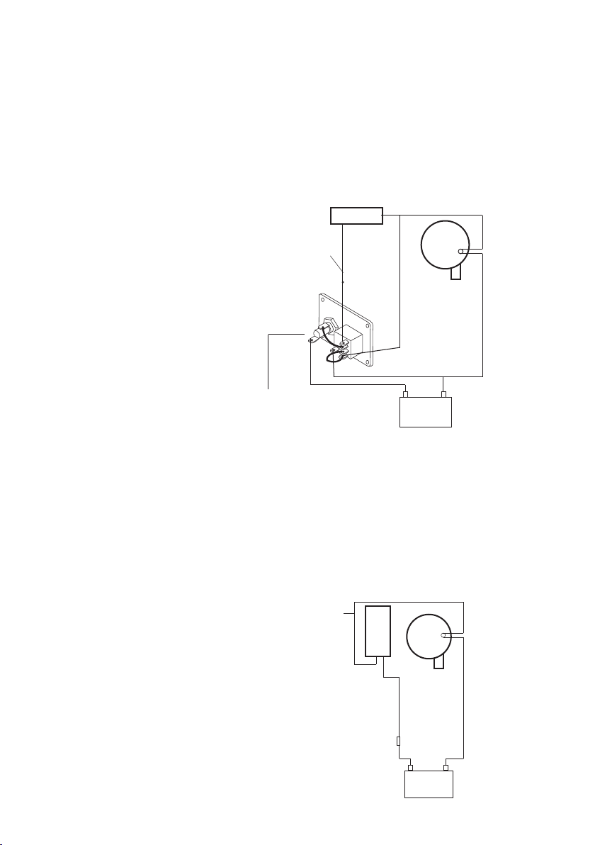
Fig 1
Elektrisk installation med SPX Johnson Pump panel
Electrical installation with SPX Johnson Pump Panel
Elektrischer Anschluss mit SPX Johnson Pump Schalttafel
Schéma de raccordement avec le tableau de commande SPX Johnson
Pump
Instalación eléctrica con panel SPX Johnson Pump
Schema collegamento elettrico con pannello di controllo SPX Johnson
Pump
A Panel
Panel
Schalttafel
Tableau de commande
Panel
Pannello
B Pump
Pump
Pumpe
Brun/vit, nr 1
Brown/white, No 1
Braunes/weiss, Nr. 1
Marron/blanc, No 1
Marrón/blanco, No 1
Marrone/blanco, No 1
Ultima Switch
A
Brun (+)
Brown (+)
Braunes (+)
Marron (+)
Marrón (+)
Marrone (+)
Pompe
Bomba
Pompa
C Batteri
DC supply
DC-Versorgung
Batterie
Batería
Obs: Dessa kablar är redan anslutna
Note: These cables are already connected
Wichtig: Kabeln schon angeschlossen
Important: Ces câbles sont déjà raccordés
Advertencia: Estos cables ya van conectados
Nota Bene: Questi cavi sono già collegati
+ -
Batteria
Elektrisk intsallation utan panel
Electrical installation without panel
Elektrischer Anschluss ohne Schalttafel
Schéma de raccordement sans tableau de commande
Instalación eléctrica sin panel
Schema collegamento elettrico senza pannello di controllo
A Pump
Pump
Pumpe
Pompe
Bomba
Pompa
B Batteri
DC supply
DC-Versorgung
Batterie
Batería
Batteria
C Säkring
Fuse
Sicherung
Fusible
Fusible
Fusibile
Brun, nr 2
Brown, No 2
Braunes, Nr. 2
Marron, No 2
Marrón, No 2
Marrone, No 2
Brun/vit, nr 1
Brown/white, No 1
Braunes/weiss, Nr. 1
Marron/blanc, No 1
Marrón/blanco, No 1
Marrone/blanco, No 1
Ultima Switch
C
+ -
Brun, nr 2 (+)
Brown, No 2 (+)
Braunes, Nr. 2 (+)
Marron, No 2 (+)
Marrón, No 2 (+)
Marrone, No 2 (+)
B
Svart (-)
Black (-)
Schwarz (-)
Noir (-)
Negro (-)
Nero (-)
C
Brun (+)
Brown (+)
Braunes (+)
A
Marron (+)
Marrón (+)
Marrone (+)
Svart (-)
Black (-)
Schwarz (-)
Noir (-)
Negro (-)
Nero (-)
B
Page 10
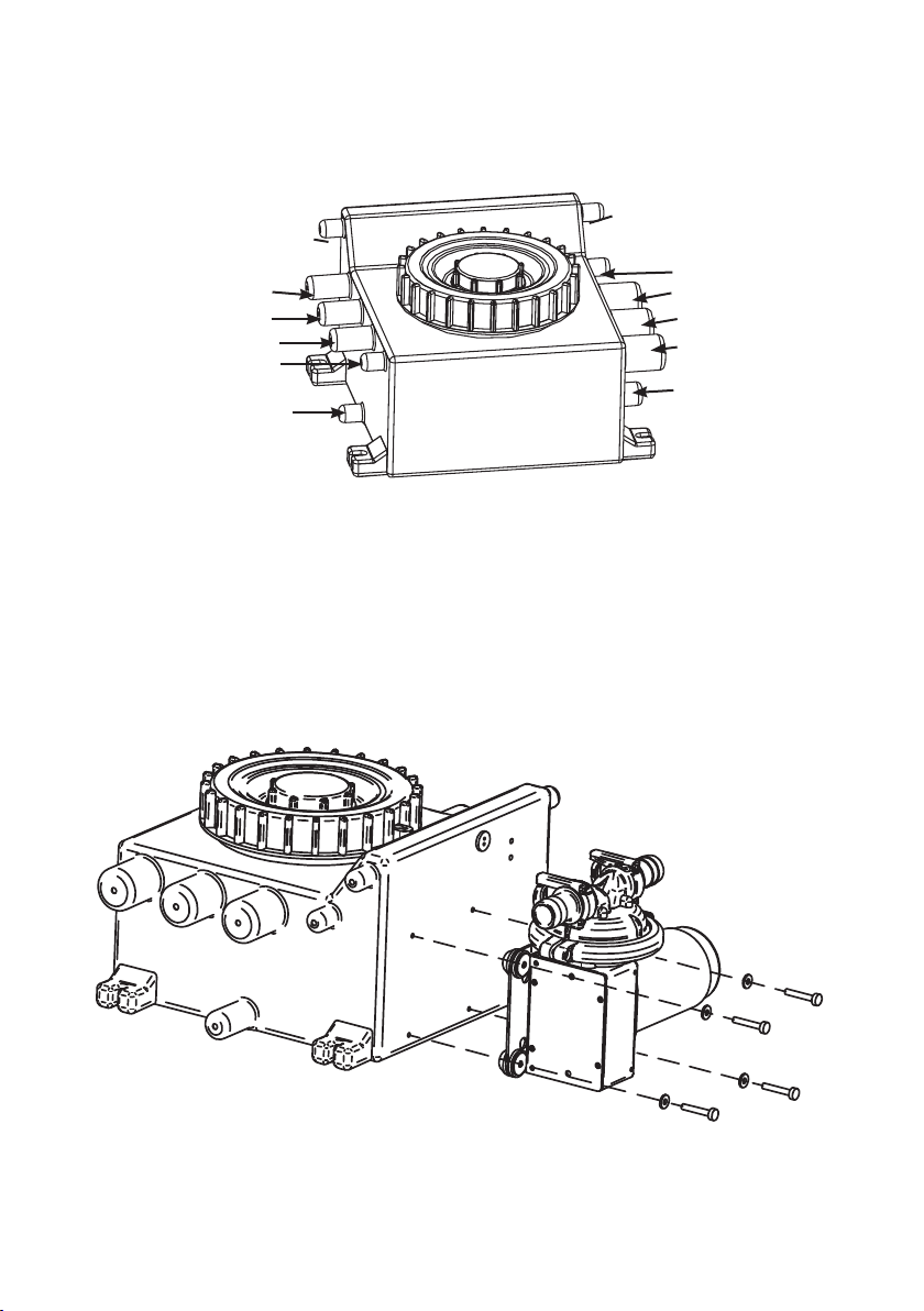
Fig 2
Air Breather line 19 mm (¾”)
Inlet 25 mm (1”)
Inlet 25 mm (1”)
Inlet 25 mm (1”)
Inlet 19 mm (¾”)
Outlet 19 mm (¾”)
Fig 3
Air Breather line 19 mm (¾”)
Inlet 19 mm (¾”)
Inlet 38 mm (1½”)
Inlet 38 mm (1½”)
Inlet 38 mm (1½”)
Outlet 25 mm (1”)
Page 11
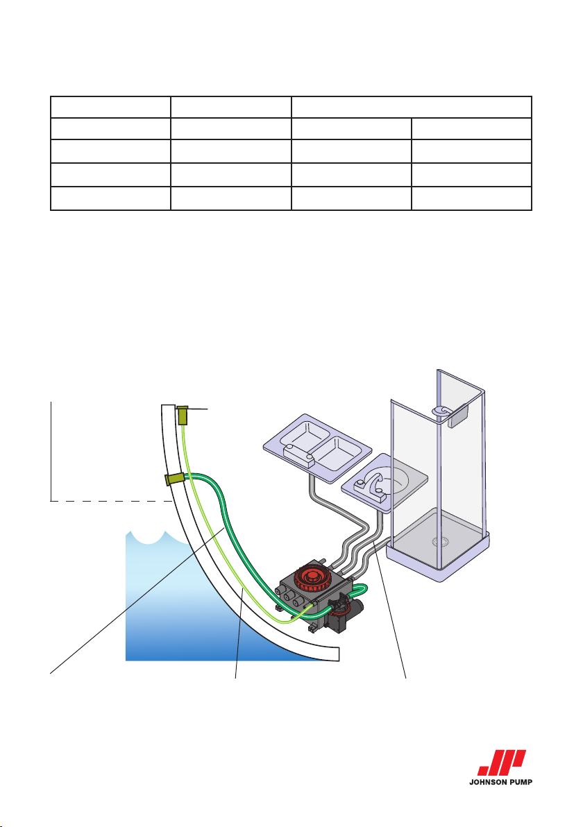
Fig 4
Port Diameter Recommended drill diameter
Imperial Metric Imperial Metric
¾"
1"
1½"
19 mm
25 mm
38 mm
7
⁄16"-9⁄16"
5
⁄8"- ¾"
11⁄8"- 1¼
12-14 mm
17-19 mm
30-32 mm
Fig 5
Låt aldrig vattnet nå utlopp eller avluftning
Never allow water to reach outlet and breather hose
Das Wasser darf nie zum Auslass- und Entlüftungsschlauch reichen
Ne laissez jamais l’eau atteindre l’orifice de sortie et la conduite du reniflard
Nunca permita que el agua llegue a la manguera de salida ni a la del respiradero
Fare in modo che l’acqua non possa mai raggiungere il punto di sbocco e il tubo di sfiato
Utlopp
Outlet
Auslass
Orifice de sortie
Salida
Bocca di efflusso
Avluftning
Air breather
Entlüftung
Reniflard
Respiradero
Sfiato dell’aria
Handfat mm.
Sink etc.
Abfluss usw.
Sentine, etc.
Sumidero, etc.
Scarico, ecc.
”Johnson Pump” and the stylized JP logo are
registered trademarks of SPX FLOW, Inc.
Page 12

Grey Water Tank
WITH ULTIMA SWITCH, 12/24 V DC
SPX FLOW TECHNOLOGY SWEDE N AB
Nastagatan 19, P.O. Box 1436
SE-701 14 Örebro, Sweden
P: +46 (0)19 21 83 00
F: +46 (0)19 27 23 77
E: johnson-pump.marine@spxflow.com
SPX FLOW, Inc. reserves the right to incorporate our latest design and
material changes without notice or obligation. Design features, materials
of construction and dimensionals data, as described in this bulletin, are
provided for your information only and should not be relied upon unless
confirmed in writing.
Please contact your local sales representative for product availability in
your region. For more information visit www.spxflow.com.
ISSUE D 01/2016 IB-122 R05
COPYRIGHT ©2016 SPX FLOW, Inc.
SPX Flow Technology Sweden AB
 Loading...