

Page 1
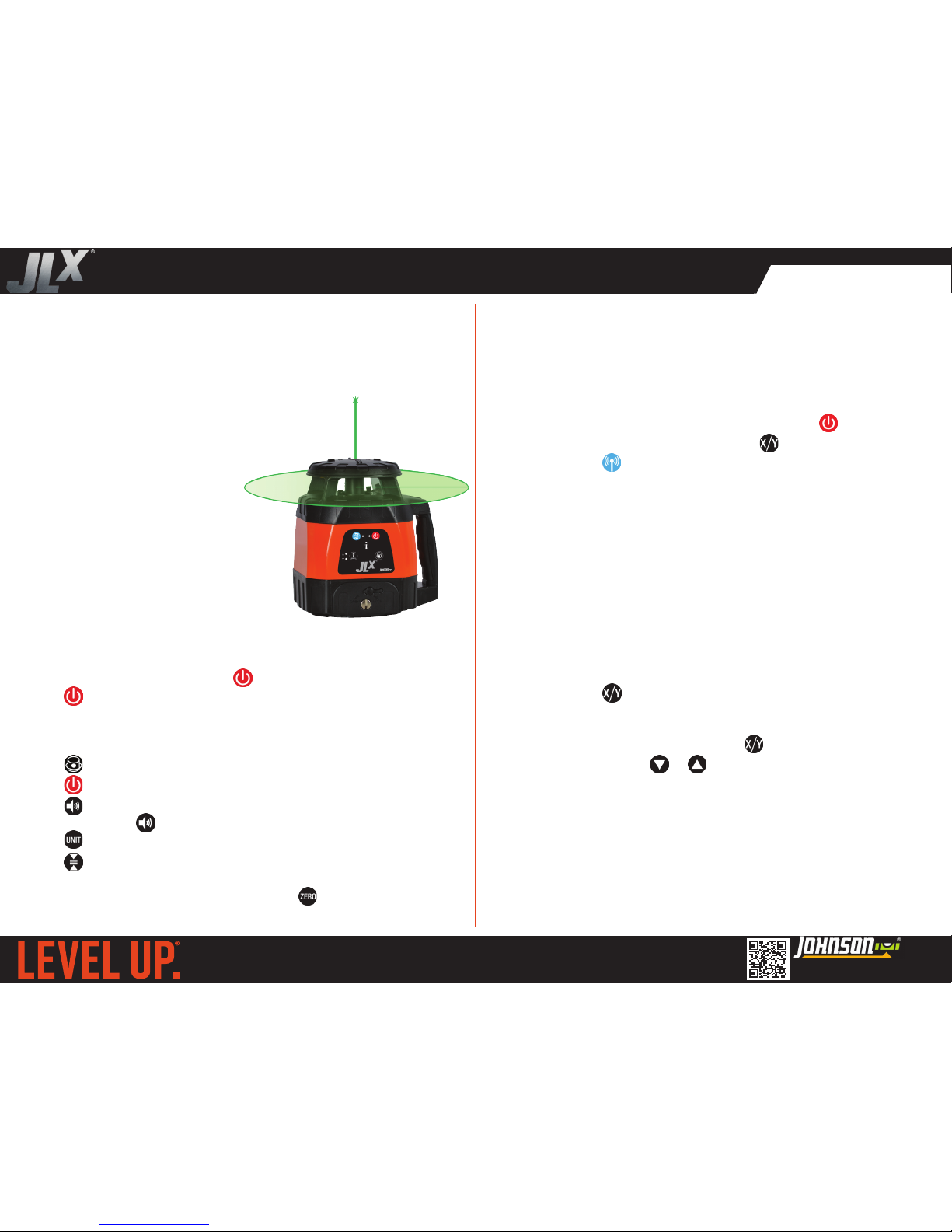
Thank you for purchasing this JLX® Tracking Rotary Laser. The JLX®
series represents Johnson’s most technologically advanced tools,
designed to help you work smarter and faster. This tool features:
• Automatic tracking of the beam to the detector
• GreenBrite® technology
• Single and dual slope
• Tilt alarm
• Scan mode
• Visual/audible out-of-level alarms
40-6590 & 40-6590I Tracking Rotary Laser Quick Start Guide
GETTING STARTED
1. Insert batteries into the laser, detector and remote.
Note: The laser will stop receiving remote/detector signals after
30 minutes of inactivity. Press on the laser to re-enable.
2. Tap to power on the laser.
In horizontal mode, the laser will self-level then begin to rotate.
In vertical mode, it will emit a plumb-down alignment laser.
Note: The laser will flash if it’s beyond its self leveling range.
3. Tap to begin rotation or adjust rotational speed.
4. Tap on the detector to power it on.
5. Tap to set the detector volume level.
6. Press and hold to turn on the detector’s backlight.
7. Tap to set the detector’s units - mm, inches or inches fraction.
8. Tap to set the detector’s sensitivity. Sensitivity will always
display in millimeters: 1mm, 5mm or 9mm (0.04”, 0.2”, 0.35”).
9. To adjust the detector zero point press . Zero osets will clear
when the detector is powered o. Maximum adjustability is 0.75”.
TRACKING MODE
Typical Applications Include:
• Drywall track installation
• Wall framing
• Tilt-up wall installation
• Pipe and drain installation
• Orthogonal layout
40-6590/40-6590I REV 1
www.johnsonlevel.com/manuals
We want to get you up and running as quickly as possible - but this quick start guide is not a replacement for reading and understanding
your operator’s manual! For complete safety & operating instructions, scan the QR code to the right to download your manual.
SINGLE-AXIS SLOPE MODE
This laser features tracking to automatically slope the beam in either
the X or Y axis. The beam slope adjusts until the beam intersects
the detector’s zero point - helpful for simplifying layout work and
connecting reference points with laser lines.
To use the rotary in tracking mode:
1. Power on the laser and the detector by pressing .
2. Set your desired slope axis by pressing on the detector.
3. Press and hold on the detector. The blue LED will illuminate.
4. Locate your detector’s zero point over the desired target.
5. The rotary will begin to sweep through a +/-5° arc until it locates
the detector’s receiving window. It will stop when it intersects the
zero point of the detector.
6. The detector’s blue LED will turn o, and slope will be fixed.
7. The detector will now function like a standard laser detector. You
can locate your interim grade points without aecting the slope
of the laser.
Single-axis slope mode angles the laser beam in either the X or Y
axis. If bumped, the laser will re-level and maintain slope.
1. Press and hold on the remote (not the detector) for 3
seconds to enable single-slope mode.
2. The laser’s X-LED will be solid & the Y LED blinking, indicating
slope can be set for the X-axis. Press again to toggle axes.
3. Use the slope buttons or to adjust slope. Tap for small
adjustments, or press and hold for larger adjustment.
Pro Tip: Set a specific slope using a grade rod and detector.
1. Set the detector a known distance from the laser. Find grade.
2. Raise or lower the detector the required amount, then adjust
slope until the detector reads the beam.
3. For example, to slope 1/4” per 10’, set the detector 10’ from the
laser and find grade. Lower the detector 1/4” and slope the laser
beam until the detector locates the beam again.
Page 2
DUAL-AXIS SLOPE MODE
Dual-axis slope mode angles the laser beam in X and Y directions, for
example when sloping a concrete slab towards a single corner.
Dual-slope mode may be used in either horizontal or vertical mode.
Vertical slope mode can speed up the process of establishing
reference lines.
When in dual-slope mode, the tilt indicator will not be functional.
Ensure the laser is not bumped while operating in dual-slope mode.
To use dual-slope mode:
1. Tap on the remote (not the detector) to start dual-slope mode.
2. The X axis indicator will blink. Use and to adjust the slope in
the X axis. Tap for minor adjustments, or press and hold for larger
adjustments.
3. Tap on the remote to toggle the axis and set slope in the Y
direction. The Y axis indicator will blink. Use and to adjust
the slope in the Y axis.
4. If the laser exceeds its slope range, the rotation will stop, the laser
will flash and the alarm will sound. If this happens, reduce the
slope in either axis until the laser resumes operation.
5. Exit dual slope mode by holding for 3 seconds. The laser will
self level and begin to spin horizontally or vertically.
Pro Tip: Instead of setting slope manually, use the tracking function.
In most cases, this will speed up the process of setting slope.
If you’re using a dierent detector than the one that came with your
rotary, you won’t be able to use the tracking function and manual
slope mode will be required.
Also, in high wind with a grade rod, detector movement can cause
instabilities in steadying the detector in tracking mode. Use manual
slope mode instead.
SCAN MODE
Scan mode simulates a laser line or dot, increasing the visibility of the
laser when working without a detector.
1. With the laser rotating, press to change from a rotational laser
to a long laser line, short laser line or dot.
2. Rotate the line or dot using or .
3. To exit scan mode, press . The laser will rotate normally.
TILT INDICATOR
SETTING THE WIRELESS CHANNEL
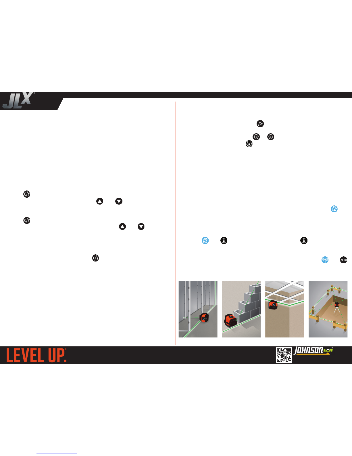
APPLICATIONS
WALL LAYOUT WALL ERECTION CEILINGS SLAB/POST LAYOUT
The tilt indicator (tilt mode) disables the laser if it’s bumped while
operating, preventing you from taking inaccurate measurements.
Tilt mode is enabled by default, indicated by the tilt mode LED.
1. The tilt LED will flash for 30 seconds, during which time the laser
will re-level and restart if bumped.
2. After 30 seconds, the tilt LED will remain on, and tilt mode will be
active. If bumped, the laser will stop spinning and flash to alert you.
3. Reset the laser after a tilt event or exit tilt mode by pressing .
1. Up to 9 channels are available when operating multiple units
nearby. The laser and detector must be on the same channel.
2. Press
and with tilt mode disabled. Press to advance the
channel. The remote LED will flash the number of times that correspond to the channel number, 1 - 9.
3. Set the detector channel - while in tracking mode, press
and
until the desired channel is displayed on the LCD screen.
40-6590/40-6590I REV 1
www.johnsonlevel.com/manuals
We want to get you up and running as quickly as possible - but this quick start guide is not a replacement for reading and understanding
your operator’s manual! For complete safety & operating instructions, scan the QR code to the right to download your manual.
 Loading...