

©2014 Johnson Level & Tool 1
Self-Leveling 3 Line or 3 Cross-Line Laser
Model No. 40-6645
Instruction Manual
Congratulations on your choice of this Self-Leveling 3 Line or 3
Cross-Line Laser. We suggest you read this instruction manual
thoroughly before using the instrument. Save this instruction manual
for future use.
This laser emits 3 laser beams that create 3 cross-lines. The laser
features quick damping, visual and audible out of range indication, and
a pendulum-locking design. Beam visibility depends upon lighting
conditions in the work area.
This is a Class IIIa laser tool and is manufactured to comply with CFR 21,
parts 1040 .10 and 1040 .11 as well as international safety rule IEC 285.
8369H-English_Manuals 10/2/14 10:19 AM Page 1
2 ©2014 Johnson Level & Tool
Table of Contents
1. Kit Contents
2. Features and Functions
3. Safety Instructions
4. Location/Content
of Warning Labels
5. Location of Parts/Components
6. Operating Instructions
7. Using the Product
8. Self-Check & Fine Calibration
9. Technical Specifications
10. Application Demonstrations
11. Care and Handling
12. Product Warranty
13. Warranty Registration
14. Accessories
15. Trouble Shooting
1. Kit Contents
Description for Model 40-6645 Qty.
Self-Leveling 3 Line or 3 Cross-Line Laser 1
Multi-functional Elevating Magnetic Bracket 1
“AA” Alkaline Batteries 3
Instruction Manual with Warranty Card 1
Soft-Sided Pouch 1
2. Features and Functions
• Indoor and outdoor use (for outdoor use, must use 40-6780
detector, not included)
• Simultaneously projects three cross-lines or one horizontal line,
one vertical line or one additional vertical line.
• Locking mechanism protects inner pendulum during transportation.
• Self-leveling with visual and audible alarms when beyond
leveling range.
• Emits continuously either a solid or pulse beam (pulse beam for
use with detector).
• Manual mode allows unit to tilt to extreme angles.
8369H-English_Manuals 10/2/14 10:19 AM Page 2
©2014 Johnson Level & Tool 3
3. Safety Instructions
Please read and understand all of the following instructions, prior
to using this tool. Failure to do so, may void the warranty.
DANGER!
Class IIIa Laser Product
Max. Power Output: ≤ 5mW
Wavelength: 625-645nm
THIS TOOL EMITS LASER RADIATION.
DO NOT STARE INTO BEAM.
AVOID DIRECT EYE EXPOSURE.
ATTENTION IMPORTANT
• Read all instructions prior to operating this laser tool. Do not remove any labels from tool.
• Do not stare directly at the laser beam.
• Do not project the laser beam directly into the eyes of others.
• Do not set up laser tool at eye level or operate the tool near a reflective surface as
the laser beam could be projected into your eyes or into the eyes of others.
• Do not place the laser tool in a manner that may cause someone to unintentionally
look into the laser beam. Serious eye injury may result.
• Do not operate the tool in explosive environments, i.e. in the presence of gases or
flammable liquids.
• Keep the laser tool out of the reach of children and other untrained persons.
• Do not attempt to view the laser beam through optical tools such as telescopes as
serious eye injury may result.
• Always turn the laser tool off when not in use or left unattended for a period of time.
• Remove the batteries when storing the tool for an extended time (more than 3 months)
to avoid damage to the tool should the batteries deteriorate.
• Do not attempt to repair or disassemble the laser tool. If unqualified persons attempt
to repair this tool, warranty will be void.
• Use only original Johnson
®
parts and accessories purchased from your Johnson
®
authorized dealer. Use of non-Johnson®parts and accessories will void warranty.
8369H-English_Manuals 10/2/14 10:19 AM Page 3
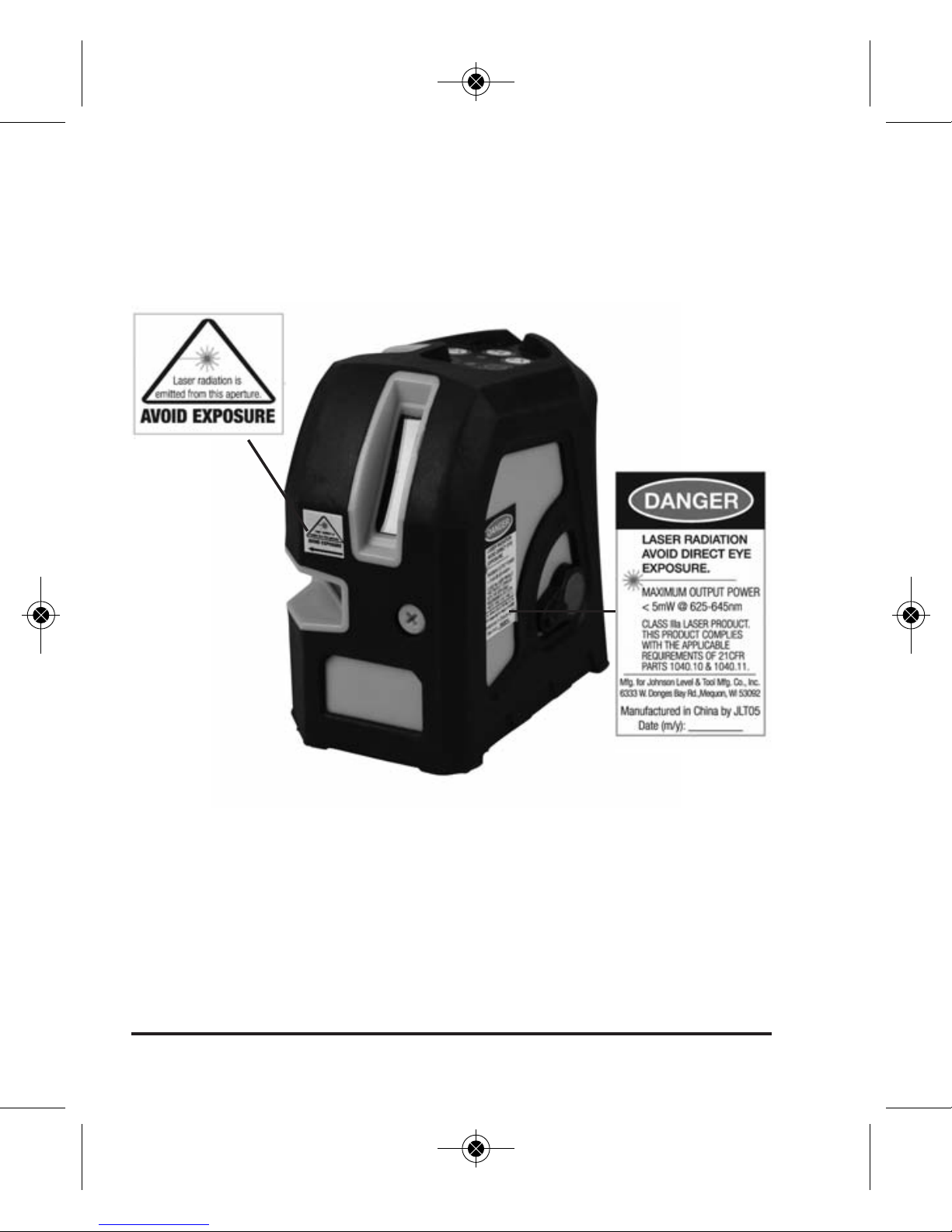
4. Location/Content of Warning Labels
4 ©2014 Johnson Level & Tool
8369H-English_Manuals 10/2/14 10:19 AM Page 4
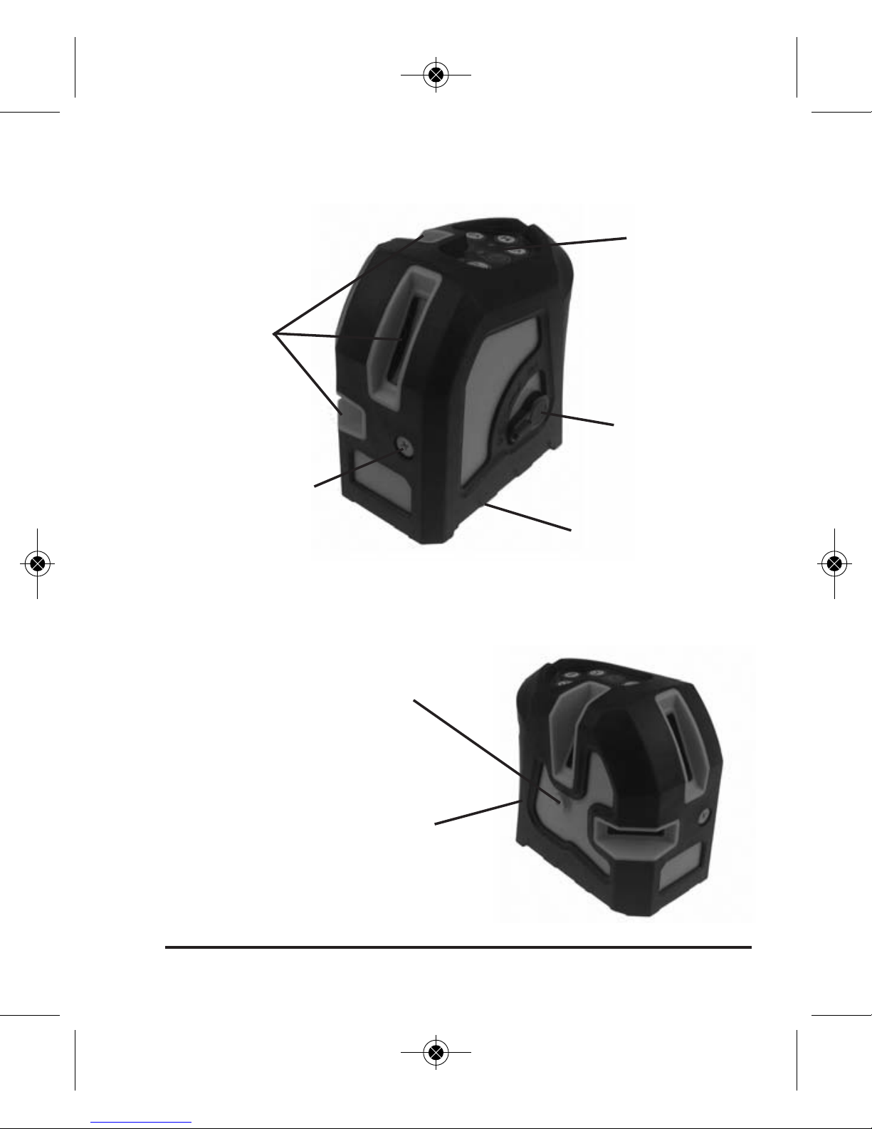
5. Location of Part/Components
Laser
Emitting
Windows
Self-Calibration
Port
Self-Calibration
Port
Battery Door
Keypad
Compensator
Lock and
On/Off Switch
1/4" Thread
©2014 Johnson Level & Tool 5
8369H-English_Manuals 10/2/14 10:19 AM Page 5
6 ©2014 Johnson Level & Tool
6. Operating Instructions
IMPORTANT: It is the responsibility of the user to verify the
calibration of the instrument before each use.
Battery Installation
Note: Always check to be sure that the on/off switch is in the off
position before removing and replacing batteries.
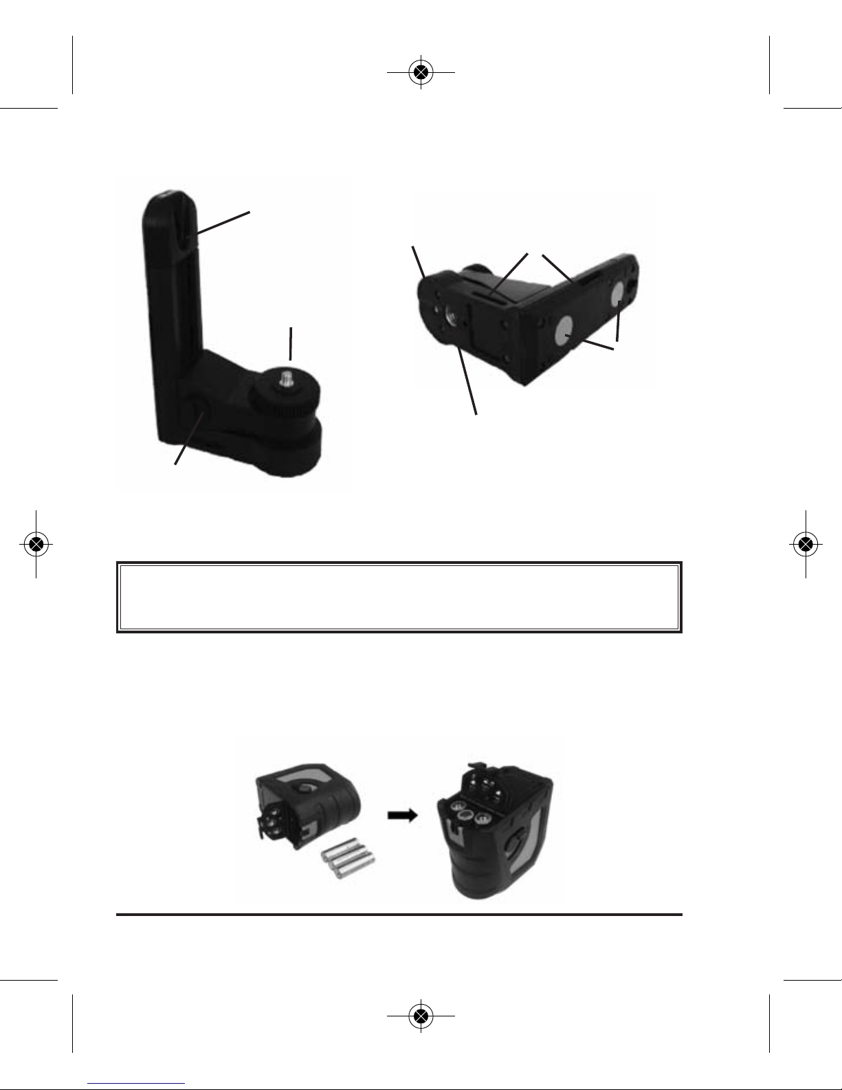
Multi-Functional Elevating Magnetic Bracket
Hang Hole
Lock/Unlock Knob
Laser
Attachment
Wheel
5/8" Thread
Belt Groove
Magnets
1/4" Thread
8369H-English_Manuals 10/2/14 10:19 AM Page 6
©2014 Johnson Level & Tool 7
Open the battery door and put 3 x AA alkaline batteries into the
battery case according to the polarity indication shown by battery
case. Then put the battery door back on.
Note:
• Pay attention to the polarity of the batteries.
• Used (discharged) batteries are hazardous waste and should be
disposed of properly.
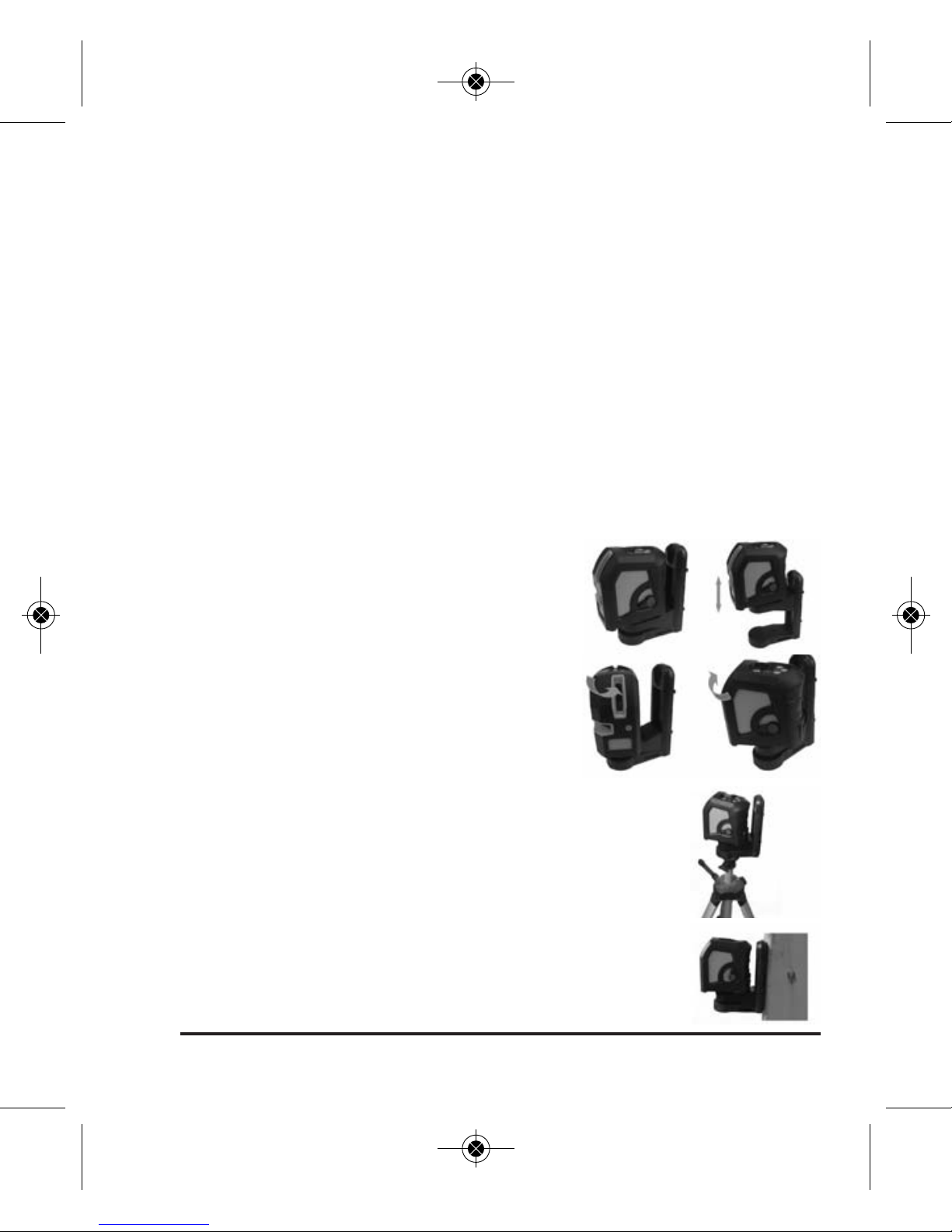
Multi-Functional Elevating Bracket
Place the laser on a horizontal surface and unlock the compensator
lock (if the laser flashes with an audible alarm, the laser is out of
its leveling range).
The laser can be attached to the bracket
and raised and lowered 2 1/2".
The laser can be attached to the bracket
and rotate 360º.
The laser can be attached to a tripod using the 5/8"
thread on the bracket.
The laser can be attached to a metallic surface.
8369H-English_Manuals 10/2/14 10:19 AM Page 7

8 ©2014 Johnson Level & Tool
The laser can be strapped to a column.
The laser can be hung using a screw.
7. Using the Product
Power LED:
Light On: Power on
Light Off: Power off
Light Flashing: Low Battery
Pulse mode LED:
Light On: Pulse mode on and the laser can be used with the
40-6780 detector (not included)
Light Off: Pulse mode is off
Manual mode LED
Manual mode button
Power LED
Vertical laser line buttons
Horizontal laser line button
Pulse mode button Pulse mode LED
8369H-English_Manuals 10/2/14 10:19 AM Page 8

©2014 Johnson Level & Tool 9
Manual mode LED:
Light On: Manual mode is on and laser can be turned on with
compensator locked
Light Off: Manual mode is off
Note: When manual mode is on, the laser does not self-level and
no out-of-level alarm is indicated.
Compensator Lock and Power On/Off Switch:
Turn the switch up, the laser is on, and the power LED is on.
Turn the switch down, the laser is off, the power LED is off.
Pulse Mode:
Push the pulse mode button to turn on. The pulse LED light will be lit
and the laser line will be dim. The laser can be used with the
40-6780 detector (not included) when the pulse mode is on.
Push the pulse mode button again to turn off the pulse mode.
The pulse LED light will not be lit and the laser line brightness will
be normal.
Manual Mode:
Press the manual mode button with the transportation lock knob in
the “Locked” position. The power LED will light and the manual
mode LED will flash. The instrument is now in the manual mode.
Note: When manual mode is on, the laser does not self-level and
no out-of-level alarm is indicated.
Press the manual mode button again and the instrument will power off.
8369H-English_Manuals 10/2/14 10:19 AM Page 9

10 ©2014 Johnson Level & Tool
Press the button to form the
horizontal line above
1. If the instrument is in manual mode and the instrument is turned to
the “Unlock” position, the instrument will exit manual mode and
enter self-leveling mode.
2. If the instrument is in the “Unlock” position, pressing the manual
mode button will not get a response.
Output of the laser line
Press the button to form the
vertical line above
Press the button to form the
vertical line above
Press all 3 buttons to form the laser
lines shown above
8369H-English_Manuals 10/2/14 10:19 AM Page 10
©2014 Johnson Level & Tool 11
8. Self-Check & Fine Calibration
IMPORTANT: It is the responsibility of the user to verify the
calibration of the instrument before each use.
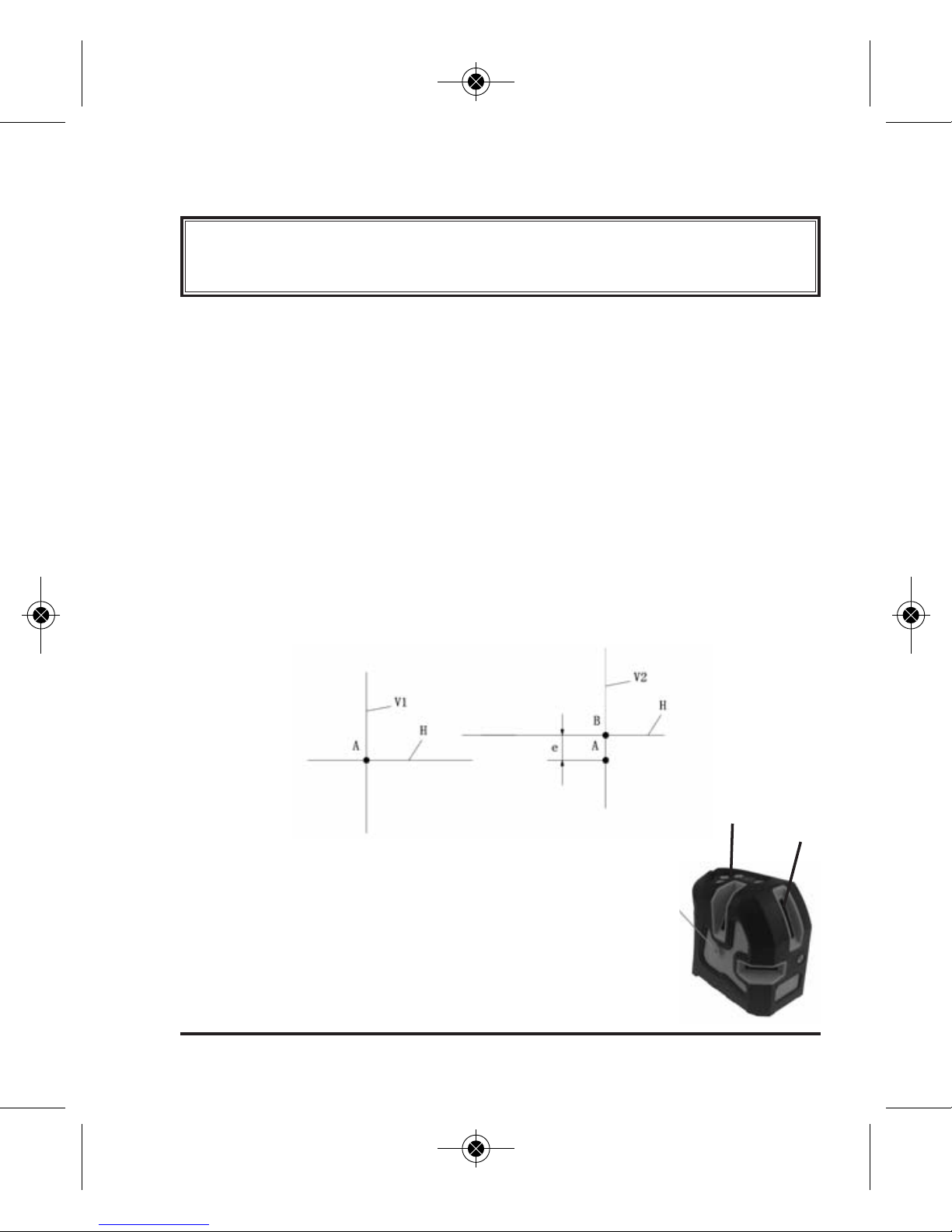
Horizontal Accuracy (transversely)
1. Locate a wall, set up an elevated tripod 15 feet away from the wall, fix
the laser to the tripod.
2. Rotate the laser until the V1 laser beam faces the wall and power on all
the laser lines, mark the cross dot of V1 and H on the wall as point “A”.
3. Rotate the laser 90º counter-clockwise and mark the cross dot of V2
line and H line as “B”.
4. Measure the distance ‘e’ between “A” and “B”. (See illustration below)
5. If the distance is greater than 3mm (0.125"), then the horizontal line
accuracy is out of tolerance and the laser needs to be calibrated.
When the horizontal line accuracy is out of
tolerance, remove the screw of the
self-calibration port. Use a 3mm hex
wrench to adjust the laser to get a
distance ≤3mm.
SelfCalibration
Port
V2
V1
8369H-English_Manuals 10/2/14 10:19 AM Page 11

12 ©2014 Johnson Level & Tool
Horizontal Accuracy (longitudinal)
1. Set up two grade rods which are 15 feet
away from each other as seen to the right
(or two parallel walls which are more than
15 feet away from each other.)
2. Mount the laser on a tripod 15 feet away
from the left grade rod, level out the bubble
by adjusting the tripod.
3. Power on the laser, mark the cross dot of V1 line and H line on the
grade rod as “C”.
4. Rotate the tripod 180º, mark the cross dot of V2 and H as “D”.
5. Move the tripod 15 feet away from the right grade rod. Line up the
cross dot with point “D” by elevating the tripod.
6. Rotate the laser 180º, measure the distance between the new projected cross dot and point “C”.
7. If the distance is greater than a 3mm (0.125"), the horizontal accuracy
of the laser is out of tolerance and the laser needs to be calibrated.
When the horizontal accuracy is out of
tolerance, remove the screw of the
self-calibration port. Use a 3mm hex
wrench to adjust the weight inside the
laser to make the distance ≤3mm
SelfCalibration
Port
Note: If you could not calibrate the accuracy through the self-calibration port, please send the instrument to Johnson Level for service.
8369H-English_Manuals 10/2/14 10:19 AM Page 12

©2014 Johnson Level & Tool 13
9. Technical Specifications
Laser Wavelength 635nm±10nm
Laser Classification Class IIIa
Maximum Power Output ≤5mW
Accuracy ±3/16"/50 ft. (±3mm/10m)
Interior Range Up to 200 ft. (60m) depending upon light
conditions
Exterior Range Up to 300 ft. (90m) with detector
(not included)
Self-leveling Range ±3°
Power Supply 3 “AA” alkaline batteries
Battery Life Approx. battery life 10 hours continuous use
Dimensions 4.25" x 2.5" x 4.25" (108 x 64 x 108mm)
Weight 1.3 lbs (0.6 Kg)
Working Temperature 14°F to 113°F (-10°C to +45°C)
Center Screw Thread 5/8" – 11
IP Protection 54
8369H-English_Manuals 10/2/14 10:19 AM Page 13

14 ©2014 Johnson Level & Tool
10. Application Demonstrations
Setting Block Walls Installing Cabinets
Installing Partitions Installing Baseboards
8369H-English_Manuals 10/2/14 10:19 AM Page 14
©2014 Johnson Level & Tool 15
11. Care and Handling
• This laser unit is a precision tool that must be handled with care.
• Avoid exposing unit to shock vibrations and extreme temperatures.
• Before moving or transporting the unit, make sure that the unit is turned off.
• Remove the batteries when storing the unit for an extended time (more than
three months) to avoid damage to the unit should the batteries deteriorate.
• Always store the unit in its case when not in use.
• Avoid getting the unit wet.
• Keep the laser unit dry and clean, especially the laser output window.
Remove any moisture or dirt with a soft, dry cloth.
• Do not use harsh chemicals, strong detergents or cleaning solvents to clean
the laser unit.
12. Product Warranty
Johnson Level & Tool offers a three year limited warranty on each of its products.
You can obtain a copy of the limited warranty for a Johnson Level & Tool
product by contacting Johnson Level & Tool's Customer Service Department,
as provided below, or by visiting our web site at www.johnsonlevel.com. The
limited warranty for each product contains various limitations and exclusions.
Do not return this product to the store/retailer or place of purchase.
Non-warranty repairs and course calibration must be done by an authorized
Johnson®service center or Johnson Level & Tool's limited warranty, if
applicable, will be void and there will be NO WARRANTY. Contact one of our
service centers for all non-warranty repairs. A list of service centers can be
found on our web site at www.johnsonlevel.com or by calling our Customer
Service Department. Contact our Customer Service Department for Return
Material Authorization (RMA) for warranty repairs (manufacturing defects
only). Proof of purchase is required.
8369H-English_Manuals 10/2/14 10:19 AM Page 15

16 ©2014 Johnson Level & Tool
NOTE: The user is responsible for the proper use and care of the product. It is the
responsibility of the user to verify the calibration of the instrument before each use.
For further assistance, or if you experience problems with this product that are not
addressed in this instruction manual, please contact our Customer Service Dept.
In the U.S., contact Johnson Level & Tool’s Customer Service Department at
888-9-LEVELS.
In Canada, contact Johnson Level & Tool’s Customer Service Department at
800-346-6682.
13. Warranty Registration
Enclosed with this instruction manual you will find a warranty
registration card to be completed for your product. You will need to
locate the serial number for your product that is located on the bottom
of the unit. PLEASE NOTE THAT IN ADDITION TO ANY OTHER
LIMITATIONS OR CONDITIONS OF JOHNSON LEVEL & TOOL'S
LIMITED WARRANTY, JOHNSON LEVEL & TOOL MUST HAVE
RECEIVED YOUR PROPERLY COMPLETED WARRANTY CARD AND
PROOF OF PURCHASE WITHIN 30 DAYS OF YOUR PURCHASE OF
THE PRODUCT OR ANY LIMITED WARRANTY THAT MAY APPLY
SHALL NOT APPLY AND THERE SHALL BE NO WARRANTY.
8369H-English_Manuals 10/2/14 10:19 AM Page 16

©2014 Johnson Level & Tool 17
14. Accessories
Johnson®accessories are available for purchase through authorized
Johnson
®
dealers. Use of non-Johnson®accessories will void any
applicable limited warranty and there will be NO WARRANTY. If you need
any assistance in locating any accessories, please contact our
Customer Service Department.
In the U.S., contact Johnson Level & Tool’s Customer Service
Department at 888-9-LEVELS.
In Canada, contact Johnson Level & Tool’s Customer Service
Department at 800-346-6682.
8369H-English_Manuals 10/2/14 10:19 AM Page 17
18 ©2014 Johnson Level & Tool
15. Trouble Shooting
• If the unit does not turn on, check the battery polarity or clean
battery terminals and install new alkaline batteries.
• If the laser does not illuminate, check the battery polarity or clean
battery terminals and install new alkaline batteries.
• If the unit is out of calibration less than 1/4" at 50', follow
calibration procedure in manual.
• If the unit is out of calibration more than 1/4" at 50', contact an
authorized Johnson service center or Johnson Level & Tool's
customer service department.
• If the unit will not calibrate, contact an authorized Johnson service
center or Johnson Level & Tool’s customer service department.
• If the unit beeps and/or flashes constantly, check to see if the unit
is being tilted to angles beyond the self-leveling range. If the unit is
being used for a level application, place onto a surface that is
within the self-leveling range. If it is still beeping and/or flashing,
the unit is out of calibration.
• If the unit turns off after a short time, clean the battery terminals
and install new alkaline batteries. Also, make sure that the on/off
knob is in the on position
.
8369H-English_Manuals 10/2/14 10:19 AM Page 18
 Loading...