

Page 1
®
1316H-English 7/10/08 9:45 AM Page 1
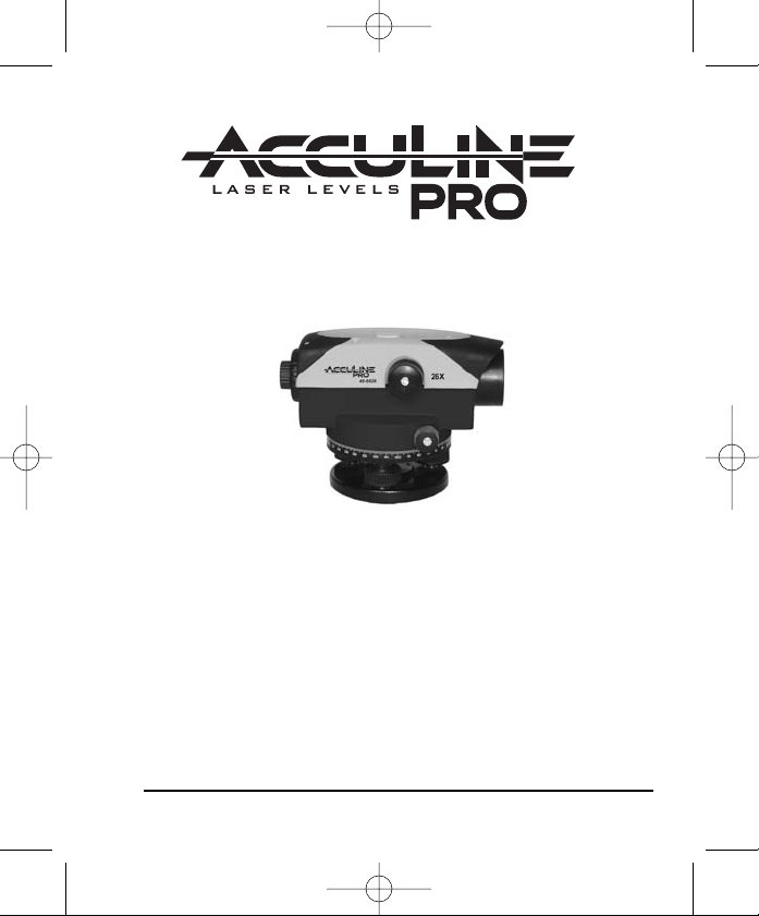
26X Automatic Level
Model No. 40-6926
Instruction Manual
Congratulations on your choice of this 26X Automatic Level. We
suggest you read this instruction manual thoroughly before using
the instrument. Save this instruction manual for future use.
©2008 Johnson Level & Tool 1
Page 2
1316H-English 7/10/08 9:45 AM Page 2
Table of Contents
1. Kit Contents
2. Features and Functions
3. Location of Parts/Components
4. Operating Instructions
5. Calibration
6. Technical Specifications
7. Care and Handling
8. Product Warranty
9. Product Registration
10. Accessories
1. Kit Contents
Description Qty.
26X Automatic Level 1
Instruction Manual with Warranty Card 1
Hard Shell Carrying Case 1
2. Features and Functions
• Water resistant, sealed construction for use in most weather
conditions
• Wire-hung, magnetically dampened compensator
• Large, easy-to-use focusing knob
• 360º horizontal circle
• Penta prism for bubble viewing
• Top-mounted optical sight for quick reference
• Fine adjustment knobs on left and right sides with endless
horizontal drive
• 1:100 stadia for distance estimation
• 5/8” x 11 threads to fit standard tripods
2 ©2008 Johnson Level & Tool
Page 3
1316H-English 7/10/08 9:45 AM Page 3
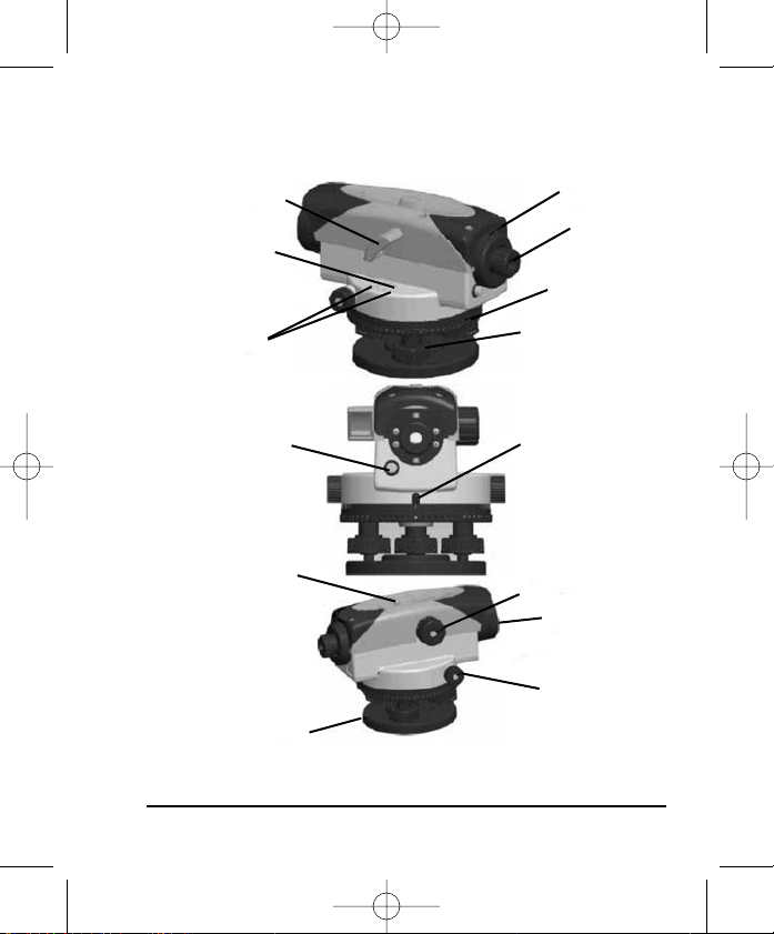
3. Location of Part/Components
Circular bubble vial
observation prism
Circular bubble vial
Adjusting screws for
circular bubble vial
Compensator
check button
Optical sight
Base plate
Eyepiece cover
Eyepiece
focusing knob
Horizontal circle
Leveling screw
Horizontal circle
reference mark
Focusing knob
Objective lens
Horizontal tangent knob
©2008 Johnson Level & Tool 3
Page 4
1316H-English 7/10/08 9:45 AM Page 4
4. Operating Instructions
IMPORTANT: It is the responsibility of the user to verify the
calibration of the instrument before each use.
Set-Up
Set the tripod up level and in a comfortable position to view through
the telescope.
central screw. Using the leveling screws, center the circular bubble.
Aiming and Focusing
Focus the cross hairs by turning the eyepiece focusing knob until the
cross hairs are sharp and black.
ocus the telescope by locating a target, such as a leveling rod, using
F
the optical sight. Looking through the eyepiece, use the focusing
knob to bring the target into sharp focus. Center the vertical hair
within the target using the horizontal tangent knobs on either side of
the instrument.
Connect the instrument to the tripod with the 5/8”-11
4 ©2008 Johnson Level & Tool
Page 5

1316H-English 7/10/08 9:45 AM Page 5
Reading measurements using a Leveling Rod
Height reading
Read the rod where it is intersected by the
horizontal hair. For example, the height reading
in Figure 1 is 2.0 ft.
Distance Measurement
Read the rod where it is intersected by the
upper and lo
wer stadia hairs. In Figure 1, these
readings are at 1.9 ft. and 2.1 ft. The stadia
ration is 1:100, therefore the distance from the
instrument to the rod is: (2.1-1.9) x 100 = 20ft.
Angle Measurement
As shown in figure 2, sight point A and note the reading on the
horizontal circ
le. Rotate the level and sight point B. The angle turned
is the difference between A and B. The angle A0B = xº = A - B.
Fig. 1
Fig. 2
©2008 Johnson Level & Tool 5
Page 6

1316H-English 7/10/08 9:45 AM Page 6
5. Calibration
5.1 Compensator Check Button
Check the compensator for proper operation before use or anytime
the operation of the instrument is in question. Push and release the
compensator check button to shake the compensator. The compensator should return to the exact horizontal position sighted before the
check button was pressed.
5.2 Circular Bubble Vial
Center the vial bubble using the leveling screws, then rotate the
instrument 180º. The bubble should remain centered (F
bubble moved from the center, the vial needs adjustment (Fig. 4).
Fig. 3 Fig. 4
Turn the leveling screws to bring the bubble halfway to center (Fig. 5).
Using the allen wrench, turn the two vial adjustment screws to center
the bubble (Fig. 6).
Repeat the above procedure until the bubble remain centered when
the level is rotated 180º.
ig. 3). If the
Fig. 5
6 ©2008 Johnson Level & Tool
Fig. 6
Page 7

1316H-English 7/10/08 9:45 AM Page 7
5.3 Line-of-Sight
The line-of-sight needs to be horizontal within 3mm of level to be accurate.
Set up and level the instrument on a tripod midway between two
leveling rods set approximately 100 ft. to 160 ft. (30m to 50m) apart.
Sight rods A and B; the height readings are a1 and b1 (Fig. 7). The
value “H” is equal to (a1 - b1). Move the instrument to within 6 ft. (2m)
of rod A and re-level. Again sight rods A and B; these height readings
are a2 and b2 (Fig. 8).
Fig. 7
Fig. 8
If a1 - b1 = a2 - b2 = H, the line-of sight is horizontal. If not, the level
should be adjusted as follows.
Because the instrument is set halfway between A and B, any error in the
line-of-sight causes both readings to be erroneous by the same amount.
Error e cancels out, so the value a1 - b1 = H is correct. Therefore,
a2 - H = b3, the adjusting value.
Fig. 9
To adjust, unscrew the eyepiece cover.
Turn the adjusting screw with the
adjusting pin (Fig. 9) until the horizontal
cross hair gives the reading b3 on rod B.
Repeat the above procedure until
{(a1 - b1) - (a2 - b2)}
©2008 Johnson Level & Tool 7
≤ 3mm.
Page 8

1316H-English 7/10/08 9:45 AM Page 8
6. Technical Specifications
Telescope Erect
Magnification 26X
Leveling accuracy ± 1/16"/200 ft. (±1.5mm/160m)
Working range Up to 350’ (100m)
Clear objective aperture 40 mm
Field of view 1º 30’
Shortest focusing distance 0.0315” (0.8m)
Stadia ratio 100
Stadia addition 0
Water resistant Yes
Sensitivity of bubble 8’ (2mm)
Circle graduation 1º
Standard deviation for
1km double-run leveling 0.0689” (1.75mm)
Compensator:
Working range ± 15’
Setting accuracy ± 0.8”
Dimensions 7.520” x 5.197” x 5.394”
(191 x 132 x 137mm)
Weight 3.395 lbs (1.54Kg)
Center screw thread 5/8” - 11
8 ©2008 Johnson Level & Tool
Page 9

1316H-English 7/10/08 9:45 AM Page 9
7. Care and Handling
Care must be taken to maintain the accuracy of the instrument.
• After each use, the instrument should be wiped clean and kept in
its carrying case.
• Remove dust from the lenses with a soft brush or a nonabrasive
wipe. Never touch the lenses with your fingers.
• Store the instrument in a dust-free area with low humidity.
• A bag of silica gel dryer is included with each instrument.
8. Product Warranty
Johnson Level & Tool offers a one year limited warranty on each its
products. You can obtain a copy of the limited warranty for a
Johnson Level & Tool product by contacting Johnson Level & Tool's
Customer Service Department as provided below or by visiting us
online at www.johnsonlevel.com. The limited warranty for each
product contains various limitations and exclusions.
Do not return this product to the store/retailer or place of purchase.
Required repair/calibration must be done by an authorized
AccuLine Pro® service center or Johnson Level & Tool's limited
warranty, if applicable, will be void and there will be NO WARRANTY.
Contact our Customer Service Department to obtain a Return Material
Authorization (RMA) number for return to an authorized service center.
Proof of purchase is required.
©2008 Johnson Level & Tool 9
Page 10

1316H-English 7/10/08 9:45 AM Page 10
NOTE: The user is responsible for the proper use and care of the
product.
It is the responsibility of the user to verify the calibration of the
instrument before each use.
For further assistance, or if you experience problems with this product
that are not addressed in this instruction manual, please contact our
Customer Service Department.
In the U.S., contact Johnson Level & Tool’s Customer Service
Department at 800-563-8553.
In Canada, contact Johnson Level & Tool’s Customer Service
Department at 800-346-6682.
9. Product Registration
Enclosed with this instruction manual you will find a warranty card to be
completed for product warranty registration. Product warranty registration
can also be completed online at our web site www.johnsonlevel.com.
You will need to locate the serial number for your product that is located
on the bottom of the level. PLEASE NOTE THAT IN ADDITION TO
THER LIMITATIONS OR CONDITIONS OF JOHNSON LEVEL &
ANY O
TOOL'S LIMITED WARRANTY, JOHNSON LEVEL & TOOL MUST
HAVE RECEIVED YOUR PROPERLY COMPLETED WARRANTY CARD
WITHIN 30 DAYS OF YOUR PURCHASE OF THE PRODUCT OR ANY
LIMITED WARRANTY THAT MAY APPLY SHALL NOT APPLY AND
THERE SHALL BE NO WARRANTY.
10 ©2008 Johnson Level & Tool
Page 11

1316H-English 7/10/08 9:45 AM Page 11
10. Accessories
AccuLine Pro® accessories are available for purchase through
authorized AccuLine Pro dealers. Use of non-AccuLine Pro accessories
will void any applicable limited warranty and there will be NO WARRANTY.
If you need any assistance in locating any accessories, please contact
our Customer Service Department.
In the U.S., contact Johnson Level & Tool’s Customer Service
Department at 800-563-8553.
In Canada, contact Johnson Level & Tool’s Customer Service
Department at 800-346-6682.
©2008 Johnson Level & Tool 11
Page 12

1316H-English 7/10/08 9:45 AM Page 12
12 ©2008 Johnson Level & Tool
 Loading...