

Page 1
!
WARNING:
4430H-English_Manuals 2/22/11 11:08 AM Page 1
Electronic Digital Theodolite
Model No. 40-6932 and 40-6935
Instruction Manual
Congratulations on your choice of this Electronic Digital Theodolite.
We suggest you read this instruction manual thoroughly before using
the instrument. Save this instruction manual for future use.
©2011 Johnson Level & Tool 1
Page 2
4430H-English_Manuals 2/22/11 11:08 AM Page 2
Table of Contents
1. Kit Contents
2. Features and Functions
3. Location of Parts/Components
4. Operating Instructions
5. Using the Product
6. Self-Check & Fine Calibration
7. Technical Specifications
8. Care and Handling
9. Product Warranty
10. Warranty Registration
11. Accessories
1. Kit Contents
Description for Model 40-6932 & 40-6935 Qty.
Electronic Digital Theodolite
Alkaline Battery Pack (batteries not included) 1
NiMH Rechargeable Battery Pack 1
NiMH Battery Charger 1
Rain Hood 1
Adjustment Tools 1
Instruction Manual with Warranty Card 1
Hard-Shell Carrying Case 1
1
2 ©2011 Johnson Level & Tool
Page 3

4430H-English_Manuals 2/22/11 11:08 AM Page 3
2. Features and Functions
• 2” or 5” angular accuracy - accurate enough for any construction job
• Vertical axis compensation - tilt sensor provides the highest level
of accuracy and can be turned on or off depending on job
requirements
• Dual LCD with large characters - easy to see angle readings
eliminate errors and reduces eye fatigue
• Backlit LCD screen and telescope reticle - allows work in low light
conditions including indoors and extended hours near dawn
and dusk
• Simple six button keypad - quick setups and simple operation with
low operator learning curve
• Large suite of programmable settings - provide multiple options for
various users and job requirements including zero position of
vertical angle
• Measurement units in degrees, gon, or mils
• 90 degree angle audible notification - for quick turning and set out
of right angles
• Instant conversion of vertical angles to percent of grade convenient for slope work
• Ni-MH rechargeable battery pack and charger - lower operating cost
with reusable batteries
• Alkaline battery pack standard - provides backup and eliminates
downtime if the charge is lost in the middle of a job
• Battery status indicator - no power surprises and allows for better
planning
• Automatic shutoff - conserves battery life when not in use - can be
disabled if desired
©2011 Johnson Level & Tool 3
Page 4
4430H-English_Manuals 2/22/11 11:08 AM Page 4
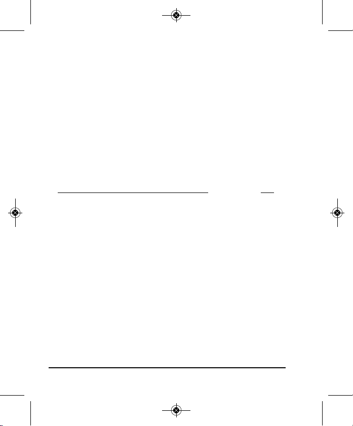
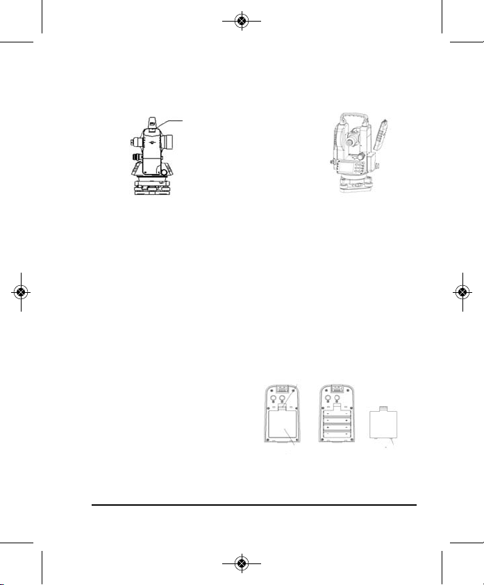
3. Location of Part/Components
Targeting Sight
Objective Lens
LCD Display
Operating Keys
Circular Vial
Tripod
Base Plate
Focusing Ring
Optical Plummet
Communication Port
Leveling Screw
Handle
Handle Screw
Center Mark &
Vertical Plate
Horizontal Fine
Motion
Horizontal Clamp
Tubular Vial
Battery Case
Eyepiece
Telescope Fine
Motion
Telescope Clamp
Tribrach
Locking Lever
4 ©2011 Johnson Level & Tool
Page 5
4430H-English_Manuals 2/22/11 11:08 AM Page 5
4. Operating Instructions
101112
1
2
3
4
5 6
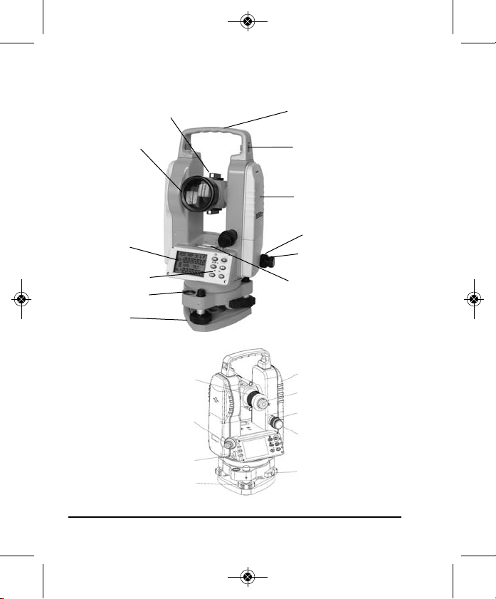
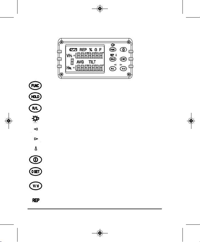
Display and Display Explanation
1. Ht - Total value of repeated angles measured
2. V - Vertical angle
3. Number of repeated measurements
4. AVG - Value of repeated angle measurements
5. HR - Angle increases with clockwise turning
6. HL - Angle increases with counterclockwise turning
7. TILT - Tilt sensor
8. F - Function mode
9. G - Angle unit GON
10. % - Vertical slope in percent
11. REP - Repeated angle measurement mode
12. Battery power indication
89
7
Note: If the display shows “b” after activating the tilt sensor, the
instrument exceeds its compensation range and the instrument
should be leveled.
©2011 Johnson Level & Tool 5
Page 6
4430H-English_Manuals 2/22/11 11:08 AM Page 6
Operating Panel and Operating Keys
Function key selection
Hold horizontal angle reading
Set horizontal-angle rotation direction
lluminating the display
Moving the cursor to the left
Moving the cursor to the right
Change the number indicated by the cursor
Power key
Zero the horizontal angle reading
Change vertical angle to percent of grade
Repeated angle measurement
6 ©2011 Johnson Level & Tool
Page 7

4430H-English_Manuals 2/22/11 11:08 AM Page 7
Preparation Before Measurement
Centering and Leveling with Optical Plummet
• Level and center the instrument precisely to ensure its best
performance.
• Extend the tripod legs to a suitable working height with equal length
legs. Spread the tripod legs and make the tripod head as level as
possible while at the same time placing the center of the tripod head
directly over the ground point. Press the leg feet firmly into the
ground and make sure the tripod legs are locked.
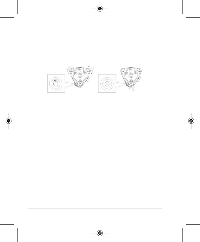
• Set the instrument carefully on the center of the tripod head
orientating the leveling screws centered with each tripod leg. Attach
the instrument to the tripod. Make sure the center mark is visible on
all three leveling screws (this ensures a complete leveling range).
• Adjust the Optical Plummet Eyepiece to focus the bullseye. Adjust the
Optical Plummet telescope focus to see the ground clearly. If you can
not see the ground point while looking through the optical plummet,
carefully lift two of the tripod legs, then pivot on the third leg,
carefully moving the tripod until the ground point is within one inch of
the reticule. Press the two tripod feet back into the ground and
recheck the optical plummet alignment. Repeat if necessary until the
ground point can be seen in the optical plummet field. Complete the
alignment by turning the leveling screws (you will not be level but
you are pointed correctly).
• Now center the instruments Circular Vial by carefully extending or
shortening the tripod legs closest to the bubble. Note: Use only two
legs. Repeat until alignment is within 6mm (1/4 inch) or better.
©2011 Johnson Level & Tool 7
Page 8
4430H-English_Manuals 2/22/11 11:08 AM Page 8
• Rotate the leveling screw 1, 2 to move the bubble to the center line
of circular level which is perpendicular to the connection line 1,2.
• Rotate the leveling screw 3 to move the bubble to the center of the
circular level.
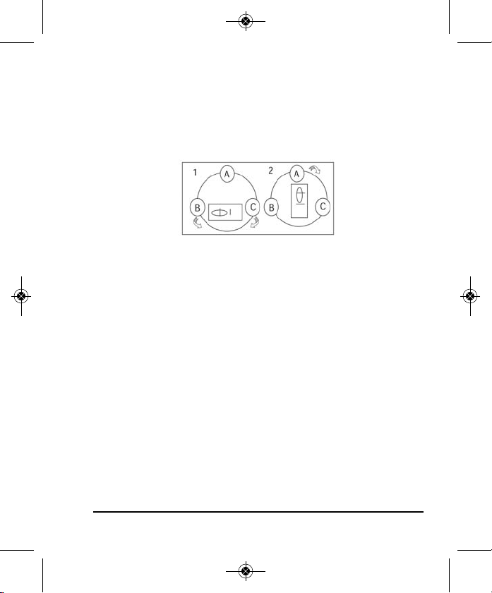
• Next use the Tubular Vial to accurately level the instrument. Unlock
and turn the instrument so that the tubular vial is parallel to BC, any
two leveling screws. Note the direction to turn the leveling screws in
the graphic. When turning the two screws, adjust them equally. The
bubble will move in the direction that your left thumb turns. To move
the bubble to the right, turn the B leveling screw in and
simultaneously turn the C leveling screw in. To move the bubble left,
move both screws out simultaneously. Once centered turn the
instrument 90º over A leveling screw and turn screw A in or out until
bubble is centered. Go back to the first position BC, and repeat until
the bubble is centered in both positions. Then from position BC turn
180º to check the adjustment. If the bubble stays centered or within
1/4 division, you are level.
8 ©2011 Johnson Level & Tool
Page 9
4430H-English_Manuals 2/22/11 11:08 AM Page 9
• Now check the ground point centering. If you are not directly on the
point, carefully loosen the tripod fastener and move the instrument on
the tripod head in an x - y direction. Do not rotate the instrument.
Recheck leveling and repeat until instrument is level and over the
ground point at the same time. With practice, this becomes easier.
©2011 Johnson Level & Tool 9
Page 10
4430H-English_Manuals 2/22/11 11:08 AM Page 10
5. Using the Product
Turning on the Instrument
Press the power key on the instrument for 2 seconds
and all the symbols will be displayed on the LCD. The
buzzer will sound twice and the horizontal angle value
and “0-set” will be displayed. When “0-set” is
displayed none of the key pads operate except for the
power key. Rotate the telescope 360º to activate the vertical
measuring mode and to activate the keypad.
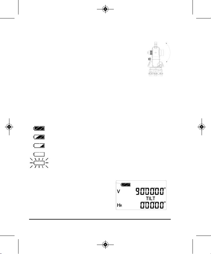
Battery Strength Indicator
The battery symbol on the LCD window displays the current
battery strength.
Full power
Effective battery
Effective battery
Weak voltage but still effective, suggest changing battery packs
Powers off automatically after symbol blinks. Replace the
battery pack or recharge it.
Battery Strength
10 ©2011 Johnson Level & Tool
Page 11
4430H-English_Manuals 2/22/11 11:08 AM Page 11
Battery Replacement
Remove Battery Box
Battery Box Button
Push down to remove
the battery box
Replace Alkaline Batteries
• Push down the battery cover tab and pull the battery cover away
from the battery box.
• Take the old batteries out and put the new batteries in paying
attention to the “+” and “-” pole.
• Snap the battery cover back into place.
Placing the Battery Box on the Instrument
Place the projection on the bottom
Hook
of the battery box into the slot on
the instrument. Push the top of
the battery box until it clicks into
place.
Battery Cover Battery Cover
©2011 Johnson Level & Tool 11
Page 12

4430H-English_Manuals 2/22/11 11:08 AM Page 12
Rechargeable Batteries
• Connect the charger to the AC outlet. Remove the battery box from
the instrument and insert plug of charger into the recharge socket
of battery box. A red indicator light on the charger means the
instrument is recharging. A green light means the instrument is
fully recharged.
• The plug should be pulled out from the rechargeable battery box
after the unit is recharged, the charger is equipped with an overcharge protective circuit.
• Rechargeable batteries can be used repeatedly for 300-500 times.
Complete discharge of the battery will shorten the battery’s life.
• Recharge batteries at least once per month to keep its longest life.
Measurement of Angle
Observing in the “Normal” and “Reverse” positions of the telescope.
The normal, or direct, position of the telescope refers to observation
with the vertical circle opposite the battery door being on the left.
The reverse position refers to observation with the vertical circle
being on the right. The mechanical errors can be offset by averaging
the values measured in the normal and reverse positions.
12 ©2011 Johnson Level & Tool
Page 13

4430H-English_Manuals 2/22/11 11:08 AM Page 13
Using the Telescope
• Point the telescope at the target and focus the eyepiece until the
crosshair can be seen clearly.
• Aim the telescope coarsely using the targeting sight. Keep a slight
distance between the targeting sight and your eye when aiming
coarsely.
• Focus the telescope by turning the focusing knob on the telescope.
Horizontal Angle “0-set”
1. Aim at target “A” using crosshair in the telescope.
2. Press 0-Set key once to set reading of horizontal
angle 0º00’00”.
• 0-set key is only available for the horizontal angle.
• Horizontal angle can be set to “0” at any time
except when the horizontal angle is in the hold status.
Measuring Horizontal and Vertical Angle (HR, V or HL, V)
Horizontal angle right rotation increment and Vertical
angle measurement (HR, V)
1. Aim at the first “A” using the center crosshair.
2. Press 0-set key once to set the reading of
horizontal angle of target “A” at 0º00’00”.
3. Rotate the instrument clockwise and aim at the
second target “B” to get the horizontal and vertical
angle of target “B”.
©2011 Johnson Level & Tool 13
Page 14

4430H-English_Manuals 2/22/11 11:08 AM Page 14
Conversion between horizontal angle right (HR)
and left (HL) rotation
1. Aim at a target “A” using the center of crosshair
in the telescope.
2. Press the R/L key to change horizontal angle mode
from HR to mode HL.
3. Measure in mode HL.
• The R/L button has no effect to the vertical angle.
• Press the R/L button again, and the horizontal angle is transformed
back from HL to HR again.
Holding the Horizontal Angle
Press the HOLD button to hold the horizontal angle. The reading will
blink while being held. The reading of the horizontal angle will
remain unchanged even if the direction of telescope is changed.
Press HOLD button again, the hold of horizontal angle is released.
1. Rotate the instrument to the target.
2. Press the HOLD key once to lock the value of the
horizontal angle, the reading will flash.
3. Press the HOLD key again to unlock the reading.
• The HOLD key has no effect to the vertical angle.
14 ©2011 Johnson Level & Tool
Page 15

4430H-English_Manuals 2/22/11 11:08 AM Page 15
Measurement of Vertical Angle
The angle position can be set as required in the initial setting.
0º
90º
270º
180º
90º
0º
180º
270º
Display of Slope
1. Press the V/% key to switch the vertical
measurement shown from degrees to percent
of grade.
2. Press the V/% key again to switch from grade
percent back to the vertical measurement
shown in degrees.
Note: When vertical angle is converted to slope, the precision of the
slope reading is two digits after the decimal. The value of slope is
displayed only within a 45º (100%). When measure angle exceeds
100%, the percent will be shown as “----”.
©2011 Johnson Level & Tool 15
Page 16
4430H-English_Manuals 2/22/11 11:08 AM Page 16
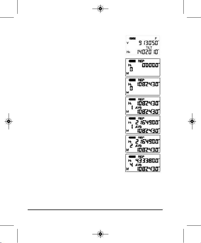
Repeat Angle Measurement
1. Press the FUNC key.
2. Press the REP key to put the instrument in
repeat mode.
3. Aim at the first target “A” and press the 0-set
key once to set the first target reading 0º00’00”.
4. Rotate the instrument and aim at the second
target “B”.
5. Press the HOLD key to hold the horizontal
angle and store it in the instrument.
6. Rotate the instrument to aim at the target “A”
again. Press R/L key to release the angle
hold status.
7. Rotate the instrument to aim at the target
“B” again.
8. Press the HOLD key to hold the horizontal
angle and store it in the instrument. Double
and average angle-value will be shown on
the display.
9. Repeat the last three steps according to
measuring requirements.
10. If needed return back to normal angle measurement, press FUNC
key, and then press the HOLD key.
16 ©2011 Johnson Level & Tool
Page 17

4430H-English_Manuals 2/22/11 11:08 AM Page 17
• The reading of horizontal angle can accumulate to reach
+1999º59’59” when in repeat angle measurement mode.
• Repeat measurement does not function if the angle between two
targets is less than 30”.
• The repeat measurement should be limited to 15 times when the
instrument is in the repeat measuring mode, otherwise the error
Err-04 will be shown. Start again from step 1.
• Err-04 will show on the display when measuring >+30” during the
repeat measurement, then go back to step 1.
• Press the FUNC key, and then press the HOLD key to withdraw
from repeat measurement and back to the original status.
Switching Between Measuring Units
This instrument has three types of angle measurement units to
choose from: DEG, GON and MIL and can be chosen in the
preliminary setting, or by following this procedure. Simultaneously
press R/L and V/%, the angle measurement units will switch between
DEG, GON and MIL.
©2011 Johnson Level & Tool 17
Page 18
4430H-English_Manuals 2/22/11 11:08 AM Page 18
Other Functions
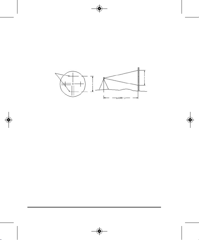
Measuring Distance Using the Stadia Method
Read the leveling rod using the stadia hair on the reticule of the
telescope. Multiply the reading by 100 to obtain the actual distance
L from the target to the measured point. (100 is the multiplication
constant error of the instrument, i.e. 1 = 1 x 100)
Stadia Hair
Tilt Sensor
This theodolite is equipped with a tilt sensor. The inclined angle of the
instrument will be compensated automatically by the tilt sensor. If the
instrument is inclined too much, a symbol “b” will be shown on the
display , this means the instrument exceeds the compensated range.
Level the instrument by hand.
To turn on the tilt sensor and hold the R/L button in for 3 seconds
after moving the telescope to get into vertical measuring mode. The
word “Tilt” will appear on the display. If the instrument is inclined
within +3º the tilt sensor can compensate the vertical angle. If the
inclination is greater than + 3º the instrument will display “b”.
18 ©2011 Johnson Level & Tool
Page 19
4430H-English_Manuals 2/22/11 11:08 AM Page 19
Sound Function
When the sound function is activated and the instrument is rotated,
the instrument will sound when the horizontal angle passes 0°, 90°,
180°, & 270°. Please refer to “initial setting” chapter to set horizontal
angle sound function.
Backlight LCD Telescope Reticle and Timing Power-Off
The display and telescope’s reticle on this theodolite are equipped
with a lighting device. Press the FUNC key twice to turn on the light.
Press the key twice again to turn it off. The instrument will
automatically turn off to save power if it has not received an
operation within 10 minutes, 20 minutes or 30 minutes. Please refer
to the “initial setting” section.
©2011 Johnson Level & Tool 19
Page 20
4430H-English_Manuals 2/22/11 11:08 AM Page 20
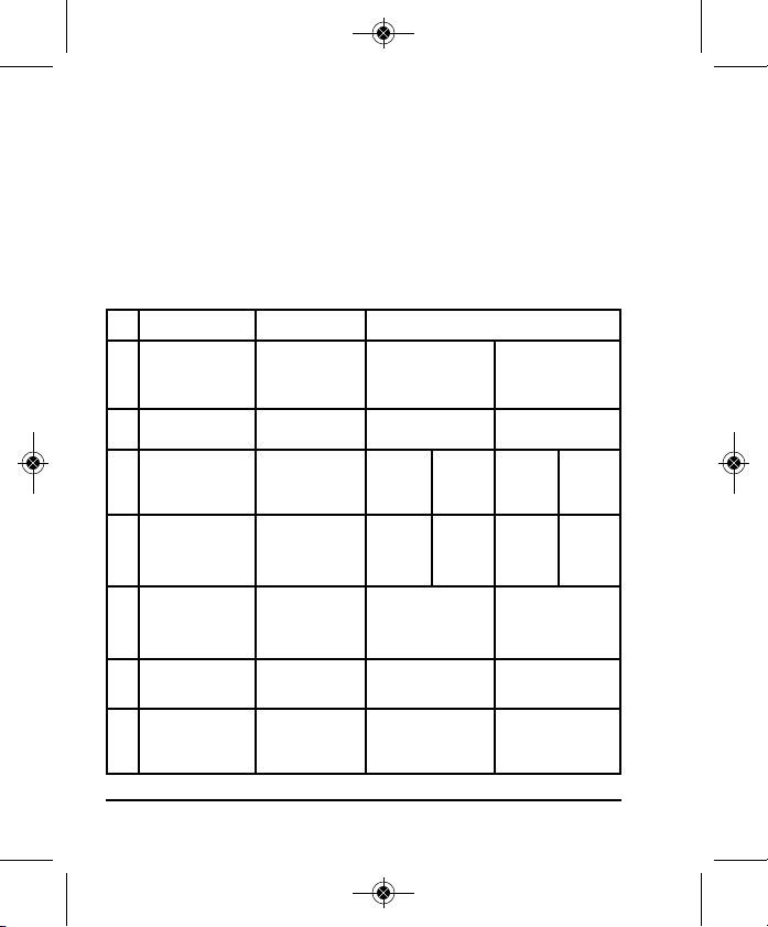
INITIAL SETTING
Initial Setting Instruction
The instrument has several settings for your option to meet different
requirements of measuring. After your purchase and before your
operation, do the initial setting for the instrument.
Item Setting
No.
1
2
3
4
5
6
7
Item Description Parameter Setting
Setting
0
DEG
Setting
0
OFF
vertical angle
Setting 0
1”
2”
Setting 0
OFF
Setting 0
Setting 0
OFF
Setting 0
OFF
Setting
Setting
10 min
Reading resolution
(minimal reading
display unit)
Sound function
Angle unit
Automatic
Shut-off
Measuring mode for
Vertical Angle
Tilt sensor Set tilt function
Data transmission
Confirming sound
Selecting angle display
unit DEG, GON, MIL
Setting interval for
automatic shut-off
without an operation
Setting measuring
mode for vertical angle
Set data transmission
40-6932
40-6935
every 90º
function
GON
Setting 1
2”
5”
Setting 1
ON
Setting
2
MIL
Setting
2
20 min
Setting 1
zenith angle
Setting 1
ON
Setting 1
ON
Setting
3
DEG
Setting
3
30 min
1
1
20 ©2011 Johnson Level & Tool
Page 21
4430H-English_Manuals 2/22/11 11:08 AM Page 21
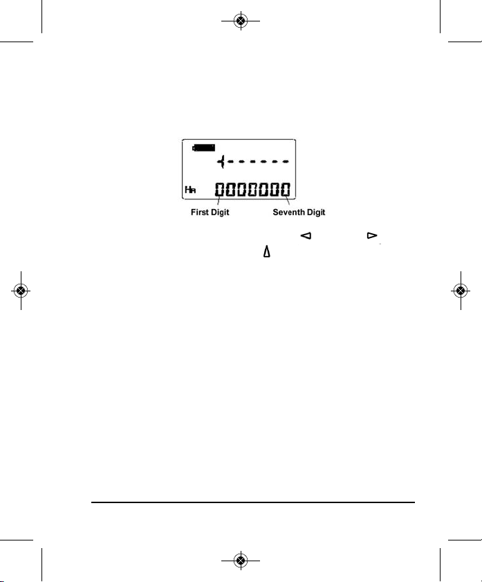
Settings
Power on the instrument, press the FUNC key once, then press the
power key once. The instrument will enter the initial setting mode
and will display as follows:
Move to the digit required by using the Left or Right keys.
Change the digit value using the up key. After changing the
various settings, press the FUNC key once, and then press Power
key once to exit the setting status and return back to the anglemeasuring function. The new settings will be saved.
Factory Settings
• Minimal Resolution Reading: 2” (40-6932), 5” (40-6935)
• Sound Function: OFF
• Angle Display Unit: 360º
• Automatic Shut Off: OFF
• Measuring-Mode for Vertical Angle: Vertical Angle
• Tilt Sensor: OFF
• Data Transmission Function: OFF
©2011 Johnson Level & Tool 21
Page 22
4430H-English_Manuals 2/22/11 11:08 AM Page 22
Error Display
Display
b Instrument exceeds its self-leveling range, level the instrument again.
Difference between every measuring value exceeds 30” during the repeated angle measurement.
Err-04
Measuring times of repeated angle measurement is more than 15. Press “0-SET” to measure again.
Err-06
Errors during the process of the vertical angle 0-set or adjusting 0-set when the inclination
Error Display & Explanation & Action
Press “0-SET” key and measure again.
to the horizontal angle exceeds 45º the instrument needs adjusting.
Note: If above errors appear, act according to corresponding actions
mentioned above. If errors still exist, then the instrument needs repair.
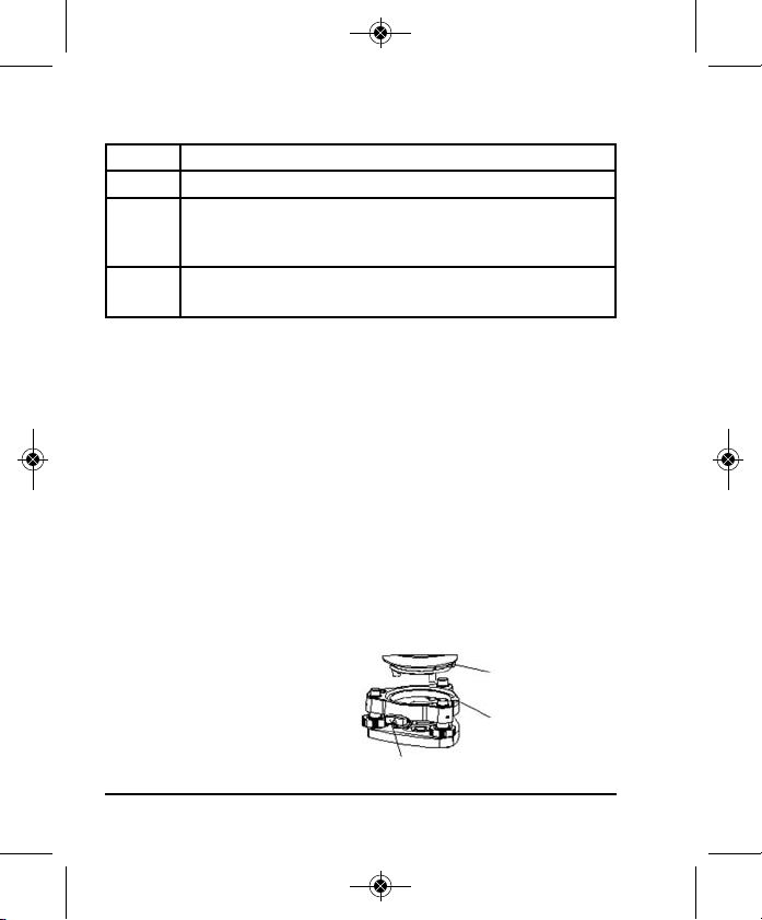
Installation and Removal of the Base
Base Removal
• Rotate the Tribrach locking lever 180° counterclockwise.
• Hold the base plate with one hand, and with the other hand lift up
the instrument by the handle.
Base Installation
• Lift the instrument by hand, and aim the positioning block to the
notch on the base plate. Mount the instrument on the base plate
carefully.
• Tighten the clamp knob on
Positioning block
the base plate.
Notch
Tribrach Locking Level
22 ©2011 Johnson Level & Tool
Page 23

4430H-English_Manuals 2/22/11 11:08 AM Page 23
6. Self-Check & Fine Calibration
• Calibration should be carried out according to the following steps
because each step’s calibration is based on its former one’s result.
Disorder of the steps will default the calibration.
• Tighten the screw after calibration. Be careful not to over tighten
because excessive tightening will damage the thread.
• After calibration, repeat the inspection to make sure that the
calibration has been successful.
Check and Calibrate The Tubular Vial
Checking
• Attach the instrument to a tripod and rough level. Position the
tubular vial parallel to a line connecting any two of the three
leveling screws on the base. Adjust the two leveling screws so that
the tubular bubble is centered.
• Turn the instrument 180º and check if the bubble remains at center.
Calibrating
• If the bubble remains at the center, no adjustment is required.
Otherwise, perform adjustment as follows:
• Using the bubble adjustment screws and adjustment pin, move the
bubble towards the tube center for half of the error.
• Turn the leveling screw to correct the other half of the error so that
the bubble is centered.
©2011 Johnson Level & Tool 23
Page 24
4430H-English_Manuals 2/22/11 11:08 AM Page 24
• Rotate the instrument 180 degrees and check
if the bubble remains centered. If the bubble
is centered, the adjustment is complete. If
not, repeat the steps until the bubble is
centered when the instrument is at any
position.
Check and Calibrate The Circular Vial
Checking
If the circular vial is centered correctly after leveling the instrument
by the tubular vial, then no further calibration is necessary. If not,
proceed with the following calibration.
Calibrating
There are three adjusting screws on the bottom
of the circular vial. When calibrating, loosen the
screw opposite to the bubble’s moving
direction (one or two), and then tighten the
screws along the bubble’s moving direction to
Circular Vial
center the bubble. The tightening of these three screws should
be consistent.
Perpendicularity of Vertical Crosshair Reticle of Telescope
Checking
• Mount the instrument on the tripod and level it carefully.
• Set a target point, A, 50 meters away from the instrument, aim the
telescope at point A .
24 ©2011 Johnson Level & Tool
Page 25
4430H-English_Manuals 2/22/11 11:08 AM Page 25
• Move the telescope using the vertical fine movement and observe
whether point A moves along the vertical hair.
• If point A moves along the vertical hair of the reticle, no adjustment
is necessary.
• Adjustment is necessary if the point A strays from the vertical
crosshair.
Clamp Screws
of Reticle Base
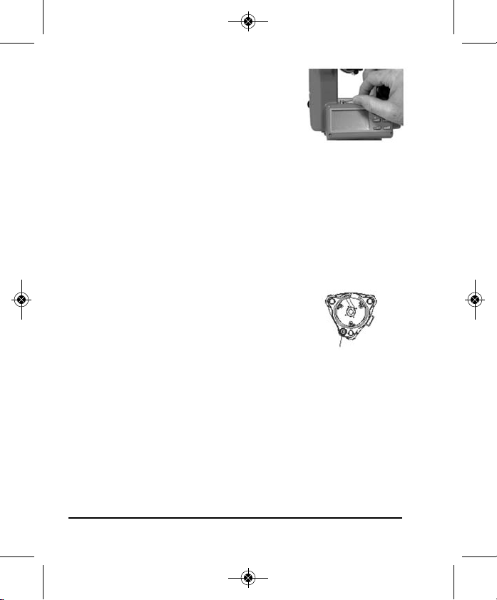
Calibrating
• Turn counterclockwise and remove the reticle cover between the
eyepiece and focusing handwheel. This will expose four reticle set
screws.
• Loosen these four set screws equally with a screwdriver. Turn the
Assembly so that point A coincides with the vertical crosshair.
• Tighten these four set screws equally and observe whether any
transversal deviation appears when point A moves along the
vertical hair. If not, the adjustment is over.
• Assemble back the protective cover to its original position.
Reticle Adjusting Screw
©2011 Johnson Level & Tool 25
Page 26

4430H-English_Manuals 2/22/11 11:08 AM Page 26
Perpendicular Degree of The Visual Axis and The Horizontal Axis
Checking
• Set two targets as high as the instrument, one in front of and the
other behind the instrument, each about 50 meters away from the
instrument. Level the instrument precisely and power it on.
• Aim at target A with crosshair of the telescope in plate-leftward
position.
• Rotate the telescope around the horizontal axis 180º to aim it in
the opposite direction.
• Aim at target B which is the same distance to target A.
• Rotate the instrument 180°. Aim at the target A, then lock the
horizontal clamp.
• Rotate the telescope 180º around the horizontal axis again. Aim at
the target C. Target C should be the same with target B.
• If not coincident, adjustment is necessary.
26 ©2011 Johnson Level & Tool
Page 27

4430H-English_Manuals 2/22/11 11:08 AM Page 27
Calibrating
• Remove the reticle cover between the eyepiece
of the telescope and the focusing handwheel.
• Set up point D between point B and C. The
distance of DC should be a quarter of BC.
Adjust the two adjusting screws to move the
reticle to have its cross aim at point D.
• Repeat above inspection steps until B and C are coincident.
• Assemble the reticle cover back to its original position.
• Loosen one screw if the vertical hair of the crosshair should be
moved, then tighten the adjusting screw on the other side about
the same number of turns. Loosen the screw counterclockwise
and tighten in the clockwise direction. The turn should be as little
as possible for both loosening and tightening.
• After above calibration, the zero reset of the upright angle should
be carried out, to reset the zero point of the upright angle.
Automatic Compensation of the Vertical Axis Incline
The instrument is equipped with the electronic incline sensor device (tilt
sensor), which can automatically compensate the vertical axis incline.
Checking
• After mounting and leveling the instrument, position the direction
of the telescope with a line between the center of the instrument
and any of its foot screws. Then tighten the horizontal braking
handwheel.
©2011 Johnson Level & Tool 27
Page 28

4430H-English_Manuals 2/22/11 11:08 AM Page 28
• Position the telescope to zero after power-on. Tighten the vertical
clamp and the instrument will display the current value in the
upright position.
• Slowly turn the foot screw in one direction about 1/2” or so (circle
distance), the value of upright angle changes correspondingly until
it disappears and the symbol “b” is shown, this means the incline
of the instrument’s axis has exceeded the compensation range.
When turning the foot screw in reverse, the instrument goes back
to display the upright angle (repeat testing and observe the
changes on the critical point), this means the compensation device
is working.
Calibrating
When the compensation doesn’t work well or works abnormally, send
the instrument to an authorized repair facility for repairs.
Vertical Plate Angle Specification ( “i” angle) and its Zero Setting
• After mounting and leveling, power on the instrument. Aim the tele
scope at any clear target A to get the reading L, which is the
upright angle plate left reading.
• Turn the telescope to the reverse position and aim at target A again
to get the reading R, which is the upright angle plate right reading.
• If upright angle is in the zenith angle mode, then i=(L+R-360°) /2.
If upright angle is in the vertical angle mode, then i=(L+R-180°)/2
or i=(L+R-540°)/2
• If the specification errors |i|° ≤ 10”, 0 reset of the upright plate
specification is necessary.
28 ©2011 Johnson Level & Tool
Page 29

4430H-English_Manuals 2/22/11 11:08 AM Page 29
Calibrating
Operating Procedures Operation Display
1. Level the instrument accurately with the long vial.
2. Power on the instrument, the vertical angle and horizontal angle
are displayed after the telescope passes zero position.
3. Press the FUNC key once, and then press the V/% key.
4. Rotate the instrument and precisely aim at the clear and stable
target A as high as the instrument in the distance.
5. Press the 0-Set key once.
6. Turn the instrument and aim the right of the vertical plate at the
same target A.
7. Press the 0-Set key and the measured values are set. The
instrument goes back to the angle measurement mode, and the
calibration is finished.
• Send the instrument to an authorized repair facility for repairs after operations are repeated many times
without any effect.
Rotate the
telescope
Aim at the
plate left
position of A
Aim at the
plate right
position of A
Check and Calibrate the Optical Plummet
To align the optical axis of the optical plummet and the vertical axis,
calibration for the optical plummet is necessary, otherwise the
vertical axis will not be on the true anchor point.
Checking
• Attach the theodolite to a tripod (no leveling required).
• Place a target under the instrument.
• Focus the image of the target then adjust the leveling screws so
that the target is centered in the reticle.
©2011 Johnson Level & Tool 29
Page 30

4430H-English_Manuals 2/22/11 11:08 AM Page 30
• Turn the instrument 180º.
• If the target remains at the center of the reticle, no adjustment is
required. Otherwise, adjust as follows.
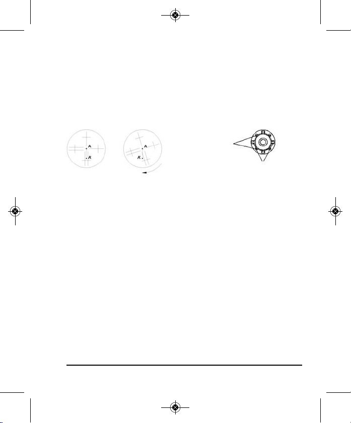
Calibrating
• Turn counterclockwise and remove the black
ring/adjusting screw cover located between
the optical eyepiece and the focusing knob.
• Place a sheet of paper under the instrument
and mark the optical plummet center mark
each time the instrument turns 90º, as shown in the figure:
point A, B, C, D.
• Line up points AC and BD to get the point of their intersection O.
• Adjust the four adjusting screws on the optical eyepiece with the
adjusting pin to align the center mark with point O.
30 ©2011 Johnson Level & Tool
Page 31

4430H-English_Manuals 2/22/11 11:08 AM Page 31
Communication Format
All data is sent in ASCII. When communication is on, vertical angle
and horizontal angle are sent in turns with 4Hz frequency.
All angle data sent begins with the letter “A” (angle), and finish with
the enter key (OXOD). Their form is as follows:
A + Angle Type Character + Display Mode Character + Angle
Value + 0X0D
Angle Type Character
“P” – Vertical Angle
“H” – Horizontal Angle
Display Mode Character
“D” – Angle In Degree (360°„)
“G” – Angle In Gon (400 Gon)
“M” – Angle In Mil (6400 Mil)
“%”– Slope Angle (-100% ~ +100%)
The transmission angle value keeps consistent with the display value
on the LCD.
©2011 Johnson Level & Tool 31
Page 32

4430H-English_Manuals 2/22/11 11:08 AM Page 32
7. Technical Specifications
Telescope
Image Erect
Magnification 30x
Aperture 1.7in (45mm)
Resolution 3’’
Angle of view 1°30’
Shortest Distance 5ft (1.4m)
Stadia Constant 100
Overall Length 6.18in (157mm)
Angle Measuring System
Angle Measurement Incremental
Minimal Reading 1”, 2”, 5”, optional
Angle Measurement Unit 360°, 400gon, 6400mil, optional
Accuracy 40-6932 - 2”, 40-6935 - 5”
Vial
Tubular Vial 30”/2mm
Circular Vial 8”/2mm
Compensator
Tilt Sensor Upright Angle Automatic
Compensation
Compensation Range +3’
32 ©2011 Johnson Level & Tool
Page 33

4430H-English_Manuals 2/22/11 11:08 AM Page 33
Optical Plummet
Imaging Erect
Magnification 3x
Focusing range 0.5m
Field Angle 5°
Display
Type LCD with Double Side
Data Input and Output
Joint (one) RS232
Power
Battery 5 “AA” Alkaline Batteries or
Rechargeable NiMH Battery Pack
Operating Voltage 6V DC
Operating Time 16 hours
Working Environment
Temperature Range -4F to +104F (-20C° to +40C°)
Size and Weight
Outside Dimension 6.29” x 5.90” x 12.99”
(160x150x330mm)
Weight 10.14 lbs (4.6kg)
©2011 Johnson Level & Tool 33
Page 34
4430H-English_Manuals 2/22/11 11:08 AM Page 34
8. Care and Handling
• Care must be taken to maintain the accuracy of the instrument.
• Do not aim the instrument’s telescope directly at the sun.
• When mounting or removing the instrument from the tripod, hold
the instrument with one hand, turn the central screw on the tripod
with the other hand to prevent the instrument from falling. If the
instrument must be carried on the tripod, hold the instrument as
vertically as possible. Never carry the instrument on the tripod in
a horizontal position over your shoulder. Any long distance
transportation should be done with the instrument in its carrying case.
• Put the instrument in its carrying case to avoid possible damage
during transportation.
• After each use, the instrument should be wiped clean and kept in
its carrying case.
• Remove dust from the lenses with a soft brush or a nonabrasive
wipe. Never touch the lenses with your fingers.
• Store the instrument in a dust-free area with low humidity.
• A bag of silica gel dryer is included with each instrument.
• Always remove the batteries when the instrument is not being used
for a long time.
34 ©2011 Johnson Level & Tool
Page 35

4430H-English_Manuals 2/22/11 11:08 AM Page 35
9. Product Warranty
Johnson Level & Tool offers a three year limited warranty on each of its products.
You can obtain a copy of the limited warranty for a Johnson Level & Tool
product by contacting Johnson Level & Tool's Customer Service Department,
as provided below, or by visiting our web site at www.johnsonlevel.com. The
limited warranty for each product contains various limitations and exclusions.
Do not return this product to the store/retailer or place of purchase.
Non-warranty repairs and course calibration must be done by an authorized
Johnson®service center or Johnson Level & Tool's limited warranty, if
applicable, will be void and there will be NO WARRANTY. Contact one of our
service centers for all non-warranty repairs. A list of service centers can be
found on our web site at www.johnsonlevel.com or by calling our Customer
Service Department. Contact our Customer Service Department for Return
Material Authorization (RMA) for warranty repairs (manufacturing defects
only). Proof of purchase is required.
NOTE: The user is responsible for the proper use and care of the product. It is the
responsibility of the user to verify the calibration of the instrument before each use.
For further assistance, or if you experience problems with this product that are not
addressed in this instruction manual, please contact our Customer Service Dept.
In the U.S., contact Johnson Level & Tool’s Customer Service Department at
888-9-LEVELS.
In Canada, contact Johnson Level & Tool’s Customer Service Department at
800-346-6682.
©2011 Johnson Level & Tool 35
Page 36

4430H-English_Manuals 2/22/11 11:08 AM Page 36
10. Warranty Registration
Enclosed with this instruction manual you will find a warranty
registration card to be completed for your product. You will need to
locate the serial number for your product that is located on the
bottom of the unit. PLEASE NOTE THAT IN ADDITION TO ANY
OTHER LIMITATIONS OR CONDITIONS OF JOHNSON LEVEL &
TOOL'S LIMITED WARRANTY, JOHNSON LEVEL & TOOL MUST
HAVE RECEIVED YOUR PROPERLY COMPLETED WARRANTY CARD
AND PROOF OF PURCHASE WITHIN 30 DAYS OF YOUR PURCHASE
OF THE PRODUCT OR ANY LIMITED WARRANTY THAT MAY APPLY
SHALL NOT APPLY AND THERE SHALL BE NO WARRANTY.
11. Accessories
Johnson®accessories are available for purchase through authorized
Johnson®dealers. Use of non-Johnson®accessories will void any
applicable limited warranty and there will be NO WARRANTY. If you
need any assistance in locating any accessories, please contact our
Customer Service Department.
In the U.S., contact Johnson Level & Tool’s Customer Service Department
at 888-9-LEVELS.
In Canada, contact Johnson Level & Tool’s Customer Service Department
at 800-346-6682.
36 ©2011 Johnson Level & Tool
 Loading...