

Page 1
®
2594H 7/29/09 10:12 AM Page 1
22X Builder’s Level
Model No. 40-6900
Instruction Manual
Congratulations on your choice of this 22X Builder’s Level. We
suggest you read this instruction manual thoroughly before using
the instrument. Save this instruction manual for future use.
©2009 Johnson Level & Tool Rev. 1 1
Page 2
2594H 7/29/09 10:12 AM Page 2
Table of Contents
1. Kit Contents
2. Features and Functions
3. Location of Parts/Components
4. Operating Instructions
5. Calibration
6. Technical Specifications
7. Care and Handling
8. Product Warranty
9. Product Registration
10. Accessories
1. Kit Contents
Description Qty.
22X Builder’s Level 1
Instruction Manual with Warranty Card 1
Hard Shell Carrying Case 1
2. Features and Functions
• Horizontal Circle - Graduated to single degrees and reads by
vernier direct to 15 minutes
• Horizontal Tangent Screw - For precise movement control.
• Built-in Sunshade - For clear sighting
• Top Mounted Leveling Vial - For effortless viewing
• Large Leveling Screws - Easy to turn
• Versatile - Ideal for leveling foundations, driveways, patios,
floors, for grading street, curbs ditches for aligning fences; or
any other light construction job.
2 ©2009 Johnson Level & Tool
Page 3
2594H 7/29/09 10:12 AM Page 3
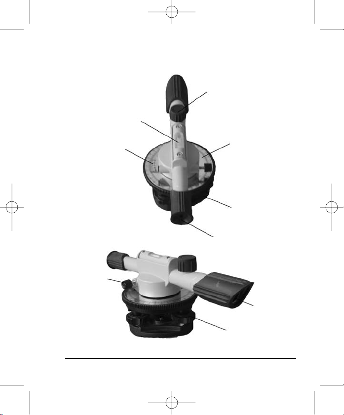
3. Location of Part/Components
Leveling
Vial
Focusing Knob
Horizontal
Vernier
Horizontal
Tangent Knob
©2009 Johnson Level & Tool 3
Horizontal
Graduated Circle
Base
Eyepiece
Telescope
Objective
Lens
Leveling
Screw
Page 4
2594H 7/29/09 10:12 AM Page 4
4. Operating Instructions
IMPORTANT: It is the responsibility of the user to verify the
calibration of the instrument before each use.
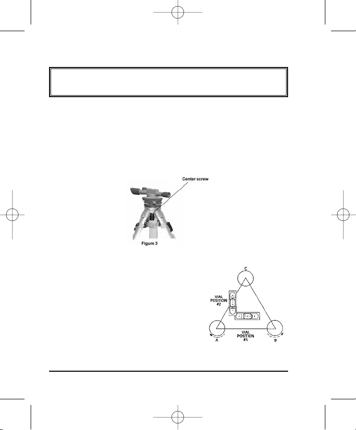
Set-Up the instrument on the tripod
When setting up the tripod, make sure the three tripod points are firmly
into the ground and the top of the tripod head is as level as possible.
Adjust the height of the tripod to a comfortable viewing height,
secure the retractable legs. Attach the instrument to the tripod head
with the center screw and tighten securely as shown in figure 3.
Leveling
Mount the instrument on the tripod and line
up the telescope vial in position #1 as sho
Then grasp screws A & B so that both thumbs
are moving in opposite directions, either
toward each other or away from each other.
Note that the bubble moves in the same
direction as your left thumb.
wn.
and
4 ©2009 Johnson Level & Tool
Page 5
2594H 7/29/09 10:12 AM Page 5
Keep about half the length engaged. When the bubble is centered in position #1, turn the instrument and observe the vial in position #2. Now center the bubble in position #2 using only screw C. The instrument should
now be leveled, but to be certain, double-check. Rotate the instrument
180º so the vial is reversed. If the bubble will not center when reversed,
follow adjustment procedure outlined under “Bubble Adjustments.”
Aiming and Focusing
Rotate the instrument by hand to aim the telescope to the far object.
te the focusing knob until the object can be observed clearly.
Rota
Rotate the horizontal tangent knob, to place the vertical cross hairs
on the object.
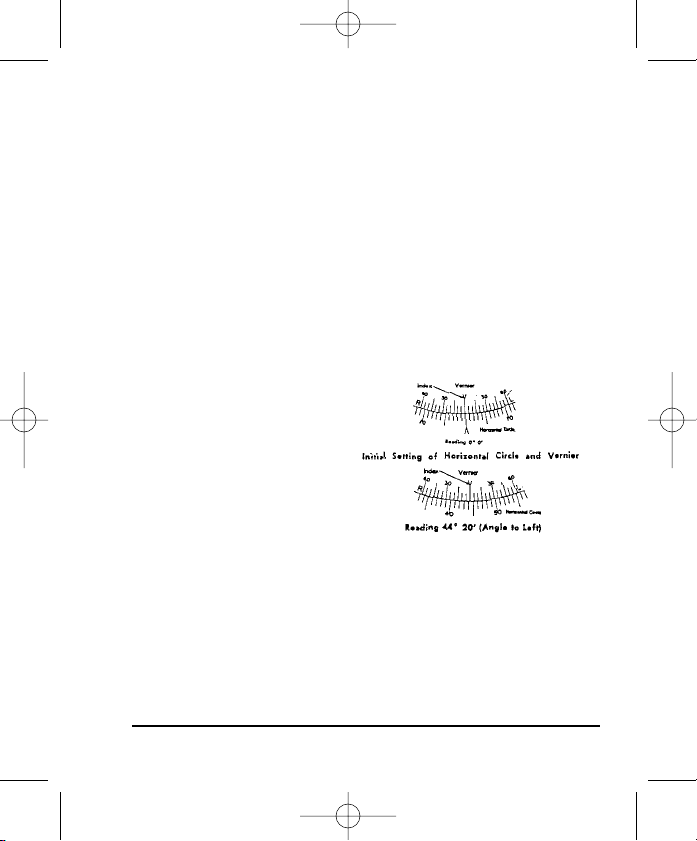
Reading the Vernier
The vernier is actually a double
, that is, two verniers in
vernier
one. This makes it possible to
read any angle turned by the
telescope, whether to the right
or to the left. For example,
consider that you have turned
an angle to the left (counterclockwise) after first having set the circle to read 0º. Refer to the
bottom figure, this is what your vernier looks like after having turned
the angle.
©2009 Johnson Level & Tool 5
Page 6

2594H 7/29/09 10:12 AM Page 6
In the illustration above, the index has
passed the 44 degree line but has not
gone as far as the 45 degree line. In
this case, the third vernier line from the
index is lined up with one of the lines
on the circle. Since each vernier line
represents 15 minutes add 45 minutes to the 44 degree reading
(3 times 15 minutes equals 45 minutes). Therefore our exact reading
is 44 degrees, 45 minutes (44º45’).
5. Calibration
5.1 Bubble adjustment
If the telescope bubble does not
remain centered after ha
leveled the instrument, and
reversed the telescope end for
end (180º) (as described under the Leveling section) the need for
adjustment is indicated. Use a 3mm hex key.
With an adjusting screw “A” facing to the right of the bubble and with
telescope directly in line with two of the three leveling screws, note
to which side the bubble is off. If to the left, loosen screw “B” and
tighten screw “A” very slightly to remove ONE-HALF the error.
Remove the other half of the error with the two level screws in line
with the telescope.
the procedure. If bubble is off to the right, loosen screw “A” and
tighten screw “B”. Otherwise the procedure is identical.
ving
If the bubble is still not exactly centered, repeat
6 ©2009 Johnson Level & Tool
Page 7

2594H 7/29/09 10:12 AM Page 7
5.2 Instrument accuracy check
Set up the instrument in an area that is as level as possible and
which is about 220 ft.
long. Place two matching level rods about
200 ft. apart with the faces toward each other. Position and level
the instrument so that the distance from the instrument to each rod
is the same. (Fig. 1)
Take a reading on each rod with the instrument. Note the difference
and record them. Next, move the instrument to another point in line
with the two level rods as shown in Fig. 2. Level the instrument and
take readings on the two level rods. The difference should be the
same (A-A should equal B-B). The difference between A-A and B-B is
the instrument error at 200 feet.
Fig. 1
Fig. 2
©2009 Johnson Level & Tool 7
Page 8

2594H 7/29/09 10:12 AM Page 8
5.3 Instrument accuracy adjustment
If the error is more than 3/16” at 100’, it is
necessary to adjust the instrument.
When adjusting the instrument:
1. Remove rubber cover to expose the two
calibration set screws.
Using a 1.5mm Allen wrench, loosen the two calibration set screws.
2.
Eyepiece seat
Set Screws
Eyepiece tube
3. Rotate the eyepiece seat to make the crosshair center in the reticle of
instrument on the same level with a known reference point. Then
rotate the eyepiece tube to make the horizontal hair on the reticle of
instrument level by using a known level reference point.
4. Tighten the two set screws and restore rubber cover to its original
position.
5.4 Determining difference in elevation
Measuring a difference in elevation from one set-up
To find the difference of elevation between two points which can be observed
from one position, set up and level your instrument about midway between these
points. Be sure that a leveling rod held on both opposite points can be read when
your telescope is level. Each point should not be greater than 150 to 200 feet
away from the instrument or you may have difficulty reading the rods. The height
of the line of sight (horizontal crosshair) above or below each of the points is
found by reading the rod.
A line of sight 69 inches above A and 40 inches above B is shown above.
Therefore, B is higher than A by 29 inches.
8 ©2009 Johnson Level & Tool
Page 9

2594H 7/29/09 10:12 AM Page 9
Suppose one of your points is below the line of sight and the other
above (Fig B.), C is 4 feet 6-1/2 inches below the line of sight, and
point D, the underside of a floor beam is 7 feet 9-3/8 inches above
the line of sight (the latter reading having been obtained by holding
the rod upside down with the foot of the rod against the beam). D is
then higher than C by an amount equal to 4 feet 6-1/2 inches plus 7
feet 9-3/8 inches, or a total of 12 feet 3-7/8 inches.
5.5 Measure the difference in elevation requiring more than
one set-up
If two points are either too far apart or at too great a difference of
tion to be observed from one set-up, the procedure shown below
eleva
is recommended. This example assumes that you want to find the
difference in elevation between points A and D. To make the finding of
this difference simple, use the convenient terms plus (+) sight and
minus (-) sight and carry the readings at each set-up as shown.
The difference of elevation between D and A is found by taking the
difference between the sum of the plus sights and the sum of the
minus sights. If the sum of the plus sights is larger, the final point is
higher than the starting point. If the sum of the minus sights is larger,
the final point is lo
©2009 Johnson Level & Tool 9
wer than than the starting point.
Page 10

2594H 7/29/09 10:12 AM Page 10
5.6 Stadia Distance Measuring
Distance measuring can be done using the stadia hairs of the reticle.
The distance between the upper stadia hair and the lower stadia hair is
set at a 1:100 ration. So if the difference is 1 foot, the person holding
the grade rod is 100 feet away from the instrument.
5.7 Measuring Horizontal Angles
To measure or lay out an angle, set the instrument over a point and
level it up.
Use a plumb bob with about six feet of string. Attach the
plumb bob string to the hook under the instrument by means of a large
loop fastened by a slipknot and adjust the plumb bob until it is clear of
the ground point. By shifting the entire instrument, set the tripod
(keeping tripod head as level as possible by estimation) so that the
plumb bob appears to be over the ground point. Next, press the legs of
the tripod into the ground and lower the plumb bob until its point is
about one-quarter inch above the point on the ground. The final
centering of the instrument can be made by loosening (about one-half
turn) any two adjacent (not opposite) leveling screws and slowly
shifting the instrument until the plumb bob is directly over the point on
the ground. Then retighten the same two leveling screws you loosened
and re-level the instrument.
To measure horizontal angles, such as FIG (Fig. 8), center and level your
10 ©2009 Johnson Level & Tool
Page 11

2594H 7/29/09 10:12 AM Page 11
instrument over point F in accordance with previous instructions.
Rotate the instrument until point E is nearly in line with the vertical
crosshair. Turn tangent screw until vertical crosshair is on point E. By
hand set the horizontal circle to read zero. Now, swing the telescope
toward point G until the vertical crosshair is exactly on point G. Your
instrument is furnished with a vernier and you will be able to read the
angle closer than a single degree. The use of a vernier is explained
earlier in this manual.
Fig. 8
Fig. 9
In layout work, it is frequently necessary to set off an angle, usually
90º. Assume that the 90º angle HIJ is to be laid off and points H and I
are shown (Fig. 9). Therefore, J is the point you are to set.
©2009 Johnson Level & Tool 11
Page 12

2594H 7/29/09 10:12 AM Page 12
6. Technical Specifications
Telescope Erect
Magnification 22X
Leveling accuracy ± 3/16"/100 ft. (±5mm/30m)
Working range Up to 200’ (60m)
Minimum focus 4’ (1.2m)
Clear objective aperture 22mm
Field of view ± 2’/100 ft. (±0.6m/30m)
Number of lenses 5
Level vial 4’ per 2mm
Horizontal circle:
Graduation diameter 110mm
Graduations 1º
Number Each 10º, 0-90-0º
Vernier Double direct to 15 min.
Weight 2.204 lbs (1Kg)
Center screw thread 5/8” - 11
12 ©2009 Johnson Level & Tool
Page 13

2594H 7/29/09 10:12 AM Page 13
7. Care and Handling
Care must be taken to maintain the accuracy of the instrument.
• After each use, the instrument should be wiped clean and kept in
its carrying case.
• Remove dust from the lenses with a soft brush or a nonabrasive
wipe. Never tough the lenses with your fingers.
• Store the instrument in a dust-free area with low humidity.
8. Product Warranty
Johnson Level & Tool offers a one year limited warranty on each its
products. You can obtain a copy of the limited warranty for a
Johnson Level & Tool product by contacting Johnson Level & Tool's
Customer Service Department as provided below or by visiting us
online at www.johnsonlevel.com. The limited warranty for each
product contains various limitations and exclusions.
Do not return this product to the store/retailer or place of purchase.
Required repair/calibration must be done by an authorized
AccuLine Pro® service center or Johnson Level & Tool's limited
warranty, if applicable, will be void and there will be NO WARRANTY.
Contact our Customer Service Department to obtain a Return Material
Authorization (RMA) number for return to an authorized service center.
Proof of purchase is required.
©2009 Johnson Level & Tool 13
Page 14

2594H 7/29/09 10:12 AM Page 14
NOTE: The user is responsible for the proper use and care of the
product.
It is the responsibility of the user to verify the calibration of the
instrument before each use.
For further assistance, or if you experience problems with this product
that are not addressed in this instruction manual, please contact our
Customer Service Department.
In the U.S., contact Johnson Level & Tool’s Customer Service
Department at 800-563-8553.
In Canada, contact Johnson Level & Tool’s Customer Service
Department at 800-346-6682.
9. Product Registration
Enclosed with this instruction manual you will find a warranty card to be
completed for product warranty registration. Product warranty registration
can also be completed online at our web site www.johnsonlevel.com.
You will need to locate the serial number for your product that is located
on the bottom of the level. PLEASE NOTE THAT IN ADDITION TO
THER LIMITATIONS OR CONDITIONS OF JOHNSON LEVEL &
ANY O
TOOL'S LIMITED WARRANTY, JOHNSON LEVEL & TOOL MUST
HAVE RECEIVED YOUR PROPERLY COMPLETED WARRANTY CARD
WITHIN 30 DAYS OF YOUR PURCHASE OF THE PRODUCT OR ANY
LIMITED WARRANTY THAT MAY APPLY SHALL NOT APPLY AND
THERE SHALL BE NO WARRANTY.
14 ©2009 Johnson Level & Tool
Page 15

2594H 7/29/09 10:12 AM Page 15
10. Accessories
AccuLine Pro® accessories are available for purchase through
authorized AccuLine Pro dealers. Use of non-AccuLine Pro accessories
will void any applicable limited warranty and there will be NO WARRANTY.
If you need any assistance in locating any accessories, please contact
our Customer Service Department.
In the U.S., contact Johnson Level & Tool’s Customer Service
Department at 800-563-8553.
In Canada, contact Johnson Level & Tool’s Customer Service
Department at 800-346-6682.
©2009 Johnson Level & Tool 15
Page 16

2594H 7/29/09 10:12 AM Page 16
16 ©2009 Johnson Level & Tool
 Loading...