

Page 1

5501H_Manuals 1/17/12 2:32 PM Page 1
One-Sided Laser Detector with Clamp for
Green Beam Lasers
Model No. 40-6760
Instruction Manual
©2012 Johnson Level & Tool 1
Page 2
5501H_Manuals 1/17/12 2:32 PM Page 2
Detector Usage
Note: A green laser uses a specific detector for the green beam.
Lasers will not perform accurately with red detectors.
1. Product Description
A laser detector is an indispensable accessory when using rotary laser
levels. The main function of the detector is to locate the position of
laser signals transmitted by rotary lasers. This detection quickly and
precisely provides the user with the horizontal and vertical references.
This product features a high level of sensitivity, a double-faced display,
ow power consumption, good reliability and easy manipulation.
l
2. Technical Specifications
Detecting accuracy Fine ±0.08" (±2mm) when range is < 492 ft. (150m)
Turn-off time 6 minutes ±1 minute
Power 3 “AAA” batteries
Sound indicator Slow sounds, rapid sounds and a continuous sound
LED indicator Up, mid, down
Dimensions 7.087" x 3.228" x 0.236" (180 x 82 x 26mm)
Weight 0.485 lb. (220g)
Others Rain and dust resistant
Coarse ±0.16" (+4mm) when range is < 492 ft. (150m)
Fine ±0.12" (±3mm) when range is > 492 ft. (150m)
Coarse ±0.24" (+6mm) when range is > 492 ft. (150m)
2 ©2011 Johnson Level & Tool - Rev. 1
Page 3
5501H_Manuals 1/17/12 2:32 PM Page 3
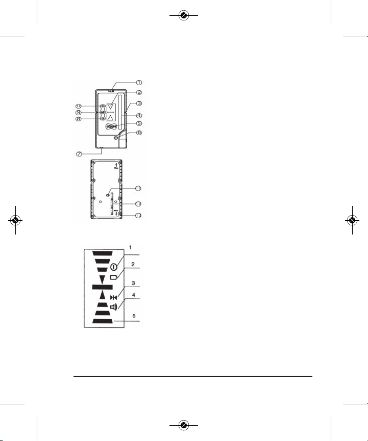
3. Components
(a) Structure
1) Horizontal vial
2) Display window
3) Center slot
4) Receiving window
5) Power button
6) Sound area
7) Battery-box
8) Sound button
9) Coarse/Fine detection button
10) Illumination button
11) Bracket mounting hole
12) Battery installation symbol
13) Scale
(b) Display
1. Power indicator
2. Low battery indicator
3. Detection indicator
4. Sound indicator
5. Detected p
osition (grade) indicator
©2012 Johnson Level & Tool 3
Page 4

5501H_Manuals 1/17/12 2:32 PM Page 4
4. Operation Guide
(a) Battery Installation
1) Rotate battery-box cap counterclockwise to open it. (A coin fits
easily into this slot.)
2) Insert 3 AAA batteries (note polarity) and then rotate battery-box
cap clockwise to close it.
3) When the battery voltage is low, the unit will display a low battery
indicator and there will be a buzzing “reminder” sound every 2-4
seconds. Yo
u will still be able to use the instrument for a short
period of time, but should change the battery soon. (Note: When
the low battery indicator is displayed, the illumination function
cannot be used. (See “Using the Illumination Function.)
Note:
a) Remove the batteries when the unit is being stored for a long time.
b) When the low battery indicator is displayed, change the battery soon.
c) Turning o
ff the sound and illumination functions will allow you
to use the unit longer.
(b) General Detector Usage
Note: Always keep the instrument stable when detecting.
1) Press the power key to turn the unit
on. The LCD display will illuminate all
the indicator segments for 0.5 second
(Fig. 6). When the indicator segments
are no longer illuminated, the detector
is ready for use. Note: The LCD display
will still have the power, detection and
sound indicators illuminated (Fig. 7).
Fig. 6 Fig. 7
4 ©2011 Johnson Level & Tool - Rev. 1
Page 5

5501H_Manuals 1/17/12 2:32 PM Page 5
2) Detecting horizontal laser level signals
• Place the unit in a vertical position (verify by checking the horizontal
vial bubble).
• Make sure the receiving window (on front of detector) is facing the
laser and is receiving the laser signal.
- If the LCD shows a “down” arrow and emits rapid sounds, this
indicates that the laser level signal is located below the detector (Fig. 8).
f the LCD shows an “up” arrow and emits slow sounds, this
- I
indicates that the
laser level signal is
located above the
detector (Fig. 9).
- If the LCD shows the
“center” mark and
emits a continuous
Fig. 8 Fig. 9 Fig. 10-1 Fig. 10-2
sound, this indicates that the laser level signal is located in the center
position on the detector.
(Fig. 10-1) LCD indicating center position of coarse detection
(Fig. 10-2) LCD indicating center position of fine d
Note: As the laser signal gradually nears the center position on the
detector, the arrow displayed will decrease in length until just the
center position signal is displayed (Fig. 11, 12, 13-1, 13-2).
etection
Fig. 11 Fig. 12 Fig. 13-1 Fig. 13-2
©2012 Johnson Level & Tool 5
Page 6

5501H_Manuals 1/17/12 2:32 PM Page 6
3) Detecting vertical laser level signals
• Place the unit in a horizontal position.
• Make sure the receiving window (on front of detector) is facing
the laser and is receiving the laser signal.
- If the LCD shows a “left” arrow and emits rapid
sounds, this indicates that the laser signal is
located to the right of the detector (Fig. 14).
- If the LCD shows a “right” arrow
and emits
slow sounds, this indicates that the laser signal
is located to the left of the detector (Fig. 15).
- If the LCD show the “center” mark and emits a
continuous sound, this indicates that the laser
signal is located in the center position on the
detector.
(Fig. 16-1) LCD indicating center position
of coarse detection
Fig. 16-1
(Fig. 16-2) LCD indicating center position of fine
detection
Fig. 14
Fig. 15
4) When you are finished u
sing the detector, press
Fig. 16-2
the power key to turn the unit off.
(c) Using the Sound Function
With the detector turned ON, press the
Sound
Silence
sound switch to alternate between
sound-on and sound-off.
Fig. 17 Fig. 18
Note: The sound indicator will also turn on and off in the
LCD screen (Fig. 17, 18).
6 ©2011 Johnson Level & Tool - Rev. 1
Page 7

5501H_Manuals 1/17/12 2:32 PM Page 7
With the sound function turned on:
- If the laser signal is above the detector, a slow sound is emitted.
- If the laser signal is below the detector, a rapid sound is emitted.
- If the laser signal is aligned on the mid portion of the detector, a
continuous sound is emitted.
Note: Whether or not the sound function is in use, there is still indicator
sound when you press the key.
sing the Coarse/Fine Detecting Switch
(d) U
With the detector turned ON, press the coarse/
fine switch. This switch alternates the unit
between coarse and fine detecting. The detector
has different check and measure precision.
(Fig. 19) LCD indicating coarse detection
(Fig. 20) LCD indicating fine detection
(e) Using the Illumination Function
With the detector turned ON, press the illumination switch. This
urns the background illumination of the LCD on and off.
switch t
(f) Power Saving Function
When the detector does not receive a laser signal for 6 continuous
minutes, and there is no detection occurring during this 6 minutes,
the unit will shut off automatically to prolong the battery’s life.
Fig. 19 Fig. 20
©2012 Johnson Level & Tool 7
Page 8

5501H_Manuals 1/17/12 2:32 PM Page 8
(g) Low Battery Indicator
If the LCD shows a blinking battery sign, it is
indicating that you have low charge on your batteries
and that you need to change them soon (Fig. 21).
If the battery power is too low, the detector will shut
off automatically. At this time, you must change the
Fig. 21
batteries in order to continue using the detector.
5. Detector Maintenance
• When you are done using the detector, return it to its packing case.
eep the detector, particularly the detecting window, clean.
• K
If unit becomes dusty, use a clean cloth to gently wipe it clean.
• Avoid knocking the detector over or allowing it to fall on the
ground.
• Although the detector is rain resistant, you should avoid
submerging the unit in water or other liquids. If detector comes
into contact with water o
r other liquids, wipe it dry immediately.
• Do not use detector around fire or expose it to fire in any way.
Blink
8 ©2011 Johnson Level & Tool - Rev. 1
 Loading...