

Page 1
Pipe Laser
Model No. 40-6690
Instruction Manual
Congratulations on your choice of this Pipe Laser. We suggest you read this instruction
manual thoroughly before using the pipe laser. Save this instruction manual for future use.
The 40-6690 pipe laser is an easy-to-use laser that provides underground contractors line,
elevation, and grade control for installing storm, sanitary, or other gravity-flow drainage pipe.
This system can also be used for tunneling, boring, pipe alignment, or any other application
requiring line, elevation, and grade control.
The pipe laser emits a highly visible red beam of laser light in a direction at a predetermined
(grade) for the alignment of gravity-flow pipe. The laser light is intercepted at the opposite end
of the pipe by the pipe laser target. To align the pipe, position it so that the pipe laser’s beam is
centered in the target.
This is a Class IIIa laser tool and is manufactured to comply with CFR 21, parts 1040.10 and
1040.11 as well as international safety rule IEC 285.
©2012 Johnson Level & Tool - Rev. 1 1
Page 2

Table of Contents
1. Kit Contents
2. Features and Functions
3. Safety Instructions
4. Location/Content
of Warning Labels
5. Location of Parts/Components
6. Operating Instructions
7. Using the Product
8. Self-Check & Fine Calibration
9. Technical Specifications
10. Care and Handling
11. Product Warranty
12. Warranty Registration
13. Accessories
1. Kit Contents
Description for Model 40-6690 Qty.
Pipe Laser 1
Rechargeable Battery pack 1
Alkaline Battery Pack (batteries not included) 1
6.4V Charger Adapter 1
12V Car Charger 1
Targets 2
Leg Sets 5
3rd Leg 1
Remote Control with 9V Battery 1
Instruction Manual with Warranty Card 1
Hard-Shell Carrying Case 1
2. Features and Functions
• Electric self-leveling
• Out of level indicator, laser beam will blink and LCD symbol will indicate
out of level position
• Large grade range
• Quickly reset the line to the center position
• Stand by mode to conserve battery
• Operates with remote control
• Various leg sets and targets for different size pipe
• Waterproof
2 ©2012 Johnson Level & Tool - Rev. 1
Page 3
3. Safety Instructions
Please read and understand all of the following instructions, prior to using this tool.
Failure to do so, may void the warranty.
DANGER!
Class IIIa Laser Product
Max. Power Output: ≤ 5mW
Wavelength: 625-645nm
THIS TOOL EMITS LASER RADIATION.
DO NOT STARE INTO BEAM.
AVOID DIRECT EYE EXPOSURE.
ATTENTION IMPORTANT
•Read all instructions prior to operating this laser tool. Do not remove any labels from tool.
•Do not stare directly at the laser beam.
•Do not project the laser beam directly into the eyes of others.
•Do not set up laser tool at eye level or operate the tool near a reflective surface as
the laser beam could be projected into your eyes or into the eyes of others.
•Do not place the laser tool in a manner that may cause someone to unintentionally
look into the laser beam. Serious eye injury may result.
•Do not operate the tool in explosive environments, i.e. in the presence of gases or
flammable liquids.
•Keep the laser tool out of the reach of children and other untrained persons.
•Do not attempt to view the laser beam through optical tools such as telescopes as
serious eye injury may result.
•Always turn the laser tool off when not in use or left unattended for a period of time.
•Remove the batteries when storing the tool for an extended time (more than 3 months)
to avoid damage to the tool should the batteries deteriorate.
•Do not attempt to repair or disassemble the laser tool. If unqualified persons attempt
to repair this tool, warranty will be void.
®
•Use only original Johnson
authorized dealer. Use of non-Johnson®parts and accessories will void warranty.
©2012 Johnson Level & Tool - Rev. 1 3
parts and accessories purchased from your Johnson
®
Page 4
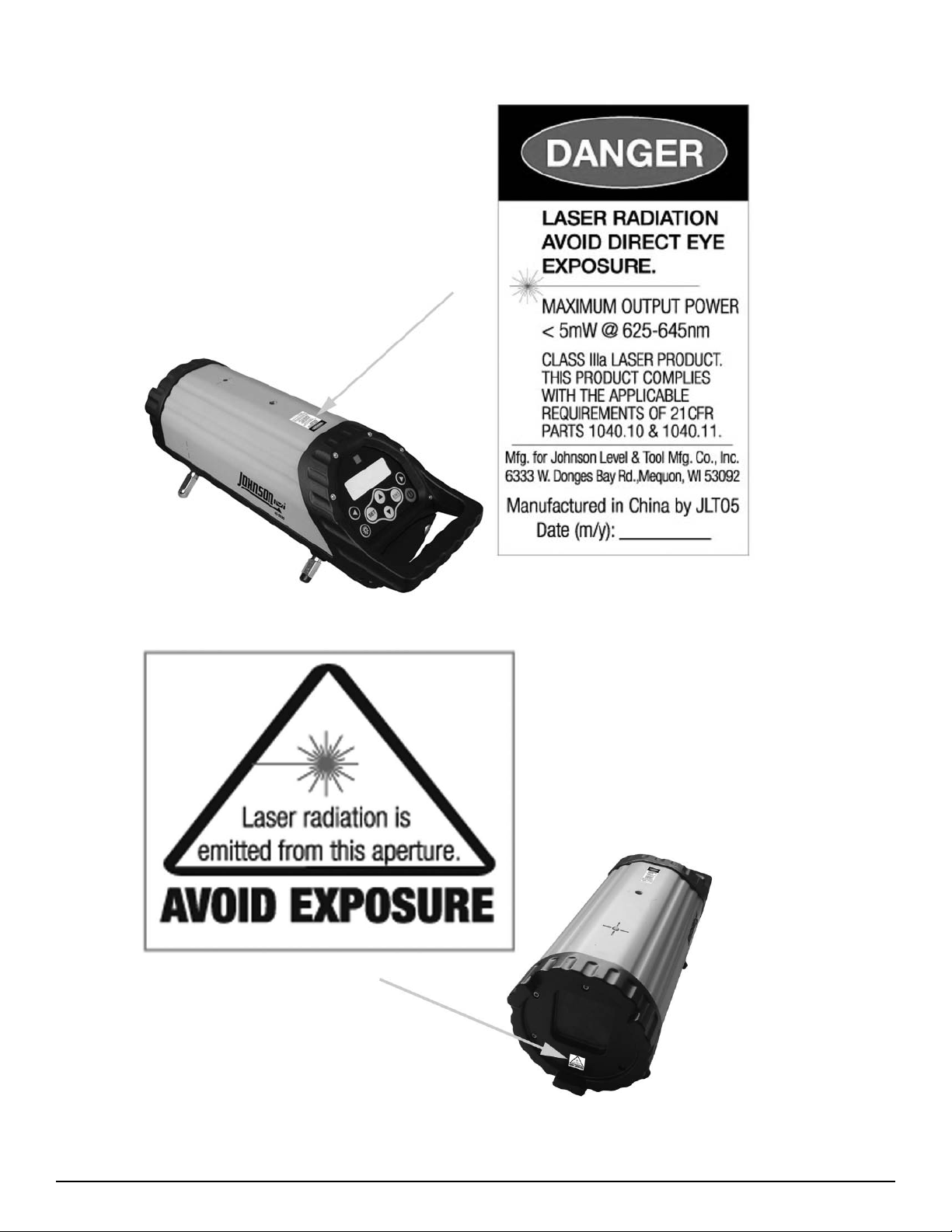
4. Location/Content of Warning Labels
4 ©2012 Johnson Level & Tool - Rev. 1
Page 5
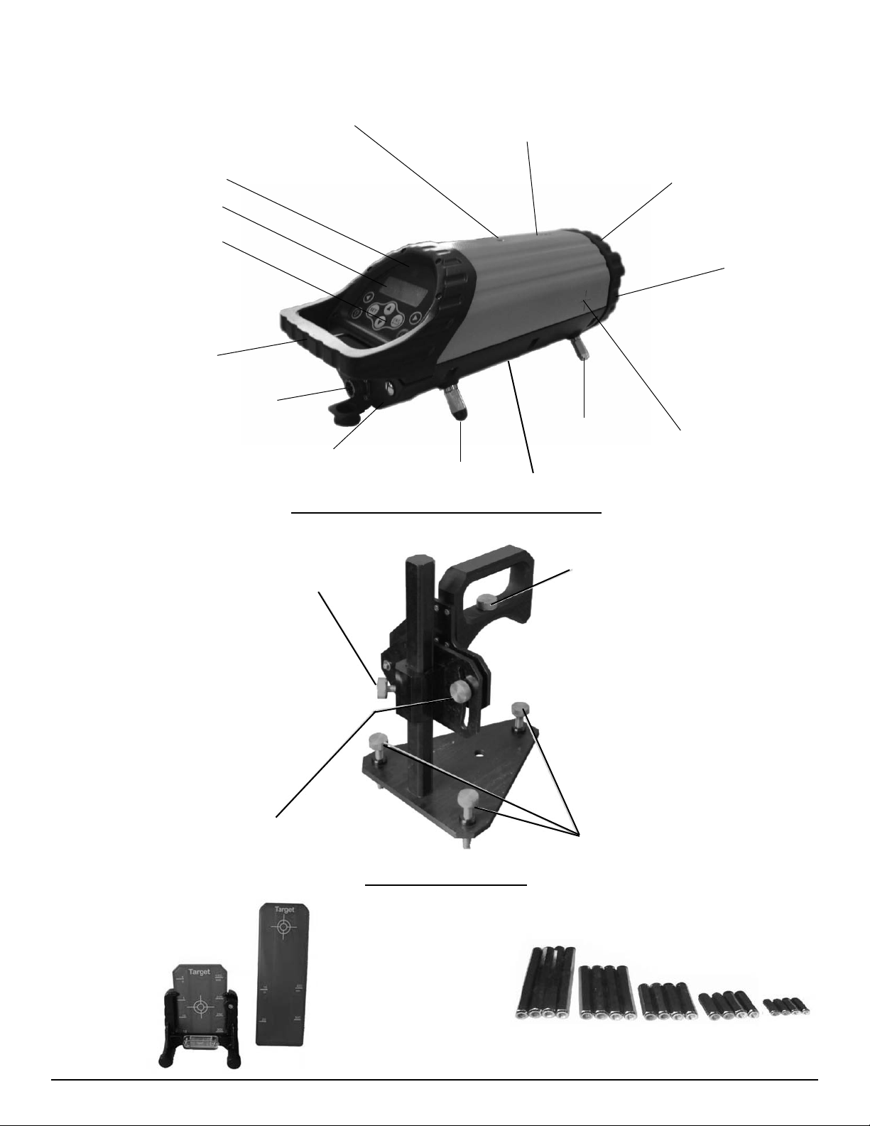
5. Location of Part/Components
1/4” Thread Mount
Line & axis pivot marker & LED
Back remote receiving window
LCD window
Keypad
Handle
External power receptacle
Battery pack
Elevating lock knob
Front leg
Back leg
Optional Adjustable Trivet Stand 40-6391
5/8 x 11 thread
Laser mounting
Front remote
receiving window
Laser Exit
Window
Grade - Axis pivot
marker
TILT lock knob
Accessories Included
Small and large targets Various leg sets
©2012 Johnson Level & Tool - Rev. 1 5
Adjusting knobs
Page 6

6. Operating Instructions
IMPORTANT: It is the responsibility of the user to verify the calibration of the
instrument before each use.
Battery installation
a) Put 4 “D” alkaline batteries into the battery pack
following the polarity direction indication. Put the
alkaline battery pack cover back, and install the
battery pack into the laser.
Alkaline battery box installation
b) Install the rechargeable battery pack into
the laser.
Rechargeable battery box installation
Recharging the battery pack
Plug the adapter into the charging port on the rechargeable battery. The adapter box
charging LED is red during the charging process, and it will turn to green when the battery
is fully charged.
Charging LED on adapter box
Charging the battery pack
outside the laser
Charging the battery pack
with rechargeable battery
pack in laser
Additional External Power Cables included
1) 12V adapter 2) Car adapter
Note: Recharge the battery when the battery indication shows low or no power.
6 ©2012 Johnson Level & Tool - Rev. 1
Page 7

Using the Optional 40-6391 Adjustable Trivet Stand:
1. When a laser is to be set on a flat surface where the laser beam is not centered in the
pipe, use model 40-6391 Trivet Stand.
2. Using this system, the elevation of the laser beam can be set by either measuring down
from a grade offset hub outside the trench or up from the floor of the manhole to the beam.
The pipe laser can be fixed to the 40-6391 adjustable trivet stand as indicated by the
picture below. Loosen the elevating lock knob to adjust the height, loosen the TILT lock
knob to adjust the TILT angle.
Laser Placement with leg sets:
Choose the different size leg sets for different size pipe. (6” or 150mm (no legs), 8” or
200mm, 10” or 250mm, 12” or 300mm, 15” or 400mm, 21” or 500mm).
For 3 feet support of the pipe laser:
Screw the silver adapter to the hole under the handle of the pipe laser. Attach one leg to
the adapter and two legs to the front of the pipe laser as shown in picture.
©2012 Johnson Level & Tool - Rev. 1 7
Page 8

7. Using the Product
Keypad
Left line - control button
Grade setting position button
Liquid Crystal Display (LCD)
Plus or minus Grade setting Percent symbol
Grade increase & decrease buttons
Right line - control button
Power button
Grade enter buttonLCD backlight & LED button
Leveling status Low battery
warning
Line position
Keypad Operating Instructions
Power button
Press the power button to turn on and off the laser. The laser will electronically
self level and display the last grade entered.
LCD backlight and LED button
Power on the laser and press the LCD/LED button . The top green LED will turn on.
The line-axis pivot marker and LED identifies the pivot point for the pipe lasers line
system. The LED also allows you to align a transit over the top of the pipe laser.
8 ©2012 Johnson Level & Tool - Rev. 1
Page 9

Left and Right line control buttons
With the laser powered on, press the left line control button to move the laser beam to the
left and press the right line control button to move the laser beam to the right. The speed
of the line movement increases as the line control button is held.
When the laser dot is moving, the LCD display will show the relevant laser dot position.
A *---- symbol flashing means the laser dot is as far left as it can go.
A -*--- symbol means the laser dot is on the left
A --*-- symbol means the laser dot is centered
A ---*- symbol means the laser dot is on the right
A ----* symbol flashing means the laser dot is as far to the right as it can go.
Center position
After the laser is turned on, pressing the left and right control buttons
simultaneously for one second, will reset the laser line to the center position.
• When the dot is moving to the center position, the LCD will display the following
symbol.
• When the laser dot is centered, the LCD will display the following symbol.
*
--*--
Grade setting position button
Turn the laser on by pressing the power button. The laser will move to the last entered
grade. Press the set button and the (+) or (-) symbol on the LCD will blink. Pressing the
set button again will make the first digit blink. Each additional press of the set button will
make the next digit to the right blink. When the last digit is blinking and the set button is
pressed again, the (+) or (-) symbol will blink.
Grade increase or decrease buttons
In the grade setting mode, with the desired digit blinking, change the grade value by
pressing these buttons. Press the up button to increase the value of the digit. Press the
down button to decrease the value of the digit. Holding the button in will change the
value quickly.
Holding the together will set the grade value to “0”.
©2012 Johnson Level & Tool - Rev. 1 9
Page 10

Grade enter button
After the desired grade has been entered on the LCD, press the grade enter button. The
laser beam will move to the new grade value. When the laser is self-leveling, the grade
value symbol will flash and will stop flashing when the laser is level.
Out of level alarm (Front and back)
If the laser is placed beyond its self-leveling range, the laser beam will blink and the LCD
symbol will blink. The laser will need to be repositioned within its self-leveling range as
noted below.
When LCD shows: user needs to lower the handle side.
When LCD shows: user needs to raise the handle side.
Out of level (right and left)
The LCD has a bubble symbol which is used to indicate the right or left out of level status.
If the laser is out of level to the right or left, it will effect its accuracy. Place the laser so
the bubble symbol is centered.
If the LCD symbol flashes, it means the left side of laser is beyond the allowed
range and the left side needs to be lowered.
If the LCD symbol does not flash, it means the left side of laser is high but still in
the allowed range.
This symbol means the laser is level and is in its idea accuracy and working
status.
If the LCD symbol does not flash, it means the ride side of laser is high but still in
the allowed range.
If the LCD symbol flashes, it means the right side of laser is beyond the allowed
range and the right side needs to be lowered.
10 ©2012 Johnson Level & Tool - Rev. 1
Page 11

Battery symbol
With the laser powered on, check the battery capacity symbol to note the power status on
the LCD display.
Full battery, no need to charge
Low battery, laser can be used
No power, battery pack needs to be recharged or new alkaline batteries must be
installed
Remote function
Included with the pipe laser is a remote control. The keypad function of the remote
control is the same as the pipe laser, except the power button .
• Press the power button on the remote when pipe laser is turned on and the pipe laser
will enter the sleep mode. The pipe laser saves the current data and powers down.
• The laser beam will be off in the sleep mode and the top LED will flash slowly. Press
the power button on the remote again and it will power up the laser. If the laser is in
the sleep mode for more than 30 minutes, it will power off automatically.
• Remote range: front (laser output window end) 165’ or 50m, back (handle end) 35’
or 10m.
©2012 Johnson Level & Tool - Rev. 1 11
Page 12

8. Self-Check & Fine Calibration
IMPORTANT: It is the responsibility of the user to verify the calibration of the
instrument before each use.
• Find a road, parking lot, or level plane (slope should be less than 4” at 100’/30m).
• Pick 2 points (A and B) whose distance is about 100’ or 30m between each other. The
distance does not need to be measured exactly, mark the 2 points.
• Put the pipe laser behind point A, turn it on, and let it warm-up for 10 minutes.
• Set the grade to be 00.000%.
• Point the laser beam to go through points A and B, make sure the laser is in its
self-leveling range.
• Accurately measure the height from the center of the laser beam point A and point B,
note it as A1 and B1.
• Put the laser behind point B and let the laser beam go through points A and B making
sure the laser is in its self-leveling range.
• Accurately measure height from the center of the laser beam to point A and point B,
note it as A2 and B2.
• Calculate A2-A1, B2-B1. If |(A2-A1) - (B2-B1)| is less than or equal to .118” or 3mm,
the accuracy is good;
If the value of A2-A1 is larger than the value of B2-B1, the laser beam is too high,
and the user needs to adjust the laser line to be leveled.
If the value of A2-A1 is smaller than the value of B2- B1, the laser beam is too low,
and the user needs to adjust the laser line to be leveled.
12 ©2012 Johnson Level & Tool - Rev. 1
Page 13

Accuracy Calibration
• Set the grade at +0.01 - +0.02%.
• Turn off the unit.
• Press and hold “left arrow” and “right arrow” keys.
• Press and release “power on/off” key when holding the “left arrow” and “right
arrow” keys.
• Hold the “left arrow” and “right arrow” keys until “mem clear” shows on the screen.
• Recalibrate the laser until |(A2-A1) - (B2-B1)| is equal or less than 3mm.
• When |(A2-A1)-(B2-B1)| is greater than 6mm, you need to contact a Johnson
®
authorized repair center.
9. Technical Specifications
Laser Wavelength 635nm±10
Laser Classification Class IIIa
Maximum Power Output ≤5mW
Grade Range -20% to +40%
Grade Display 00.001%
Accuracy ±1/16” at 100’ (±5mm at 100m; ±10 arc sec)
Self-Leveling Range ± 5°
Left and Right Scan ± 4°
Power Supply 4 “D” alkaline batteries, rechargeable
Ni-MH battery pack, 12V adapter, car adapter
Battery Life Ni-MH: Approximately 64 hours continuous use
Alkaline: Approximately 40 hours continuous use
Dimensions 5.19” x 14.96”
(132 x 380mm)
Weight 13.2 lbs. (6 Kg)
Working Temperature -4°F to 122°F (-20°C to +50°C)
IP Protection Class 68 nitrogen purged
©2012 Johnson Level & Tool - Rev. 1 13
Page 14

10. Care and Handling
• This laser unit is a precision tool that must be handled with care.
• Avoid exposing unit to shock vibrations and extreme temperatures.
• Before moving or transporting the unit, make sure that the unit is turned off.
• Remove the batteries when storing the unit for an extended time (more than three
months) to avoid damage to the unit should the batteries deteriorate.
• Always store the unit in its case when not in use.
• Keep the laser unit dry and clean, especially the laser output window. Remove any
moisture or dirt with a soft, dry cloth.
• Do not use harsh chemicals, strong detergents or cleaning solvents to clean the
laser unit.
11. Product Warranty
Johnson Level & Tool offers a three year limited warranty on each of its products. You can
obtain a copy of the limited warranty for a Johnson Level & Tool product by contacting
Johnson Level & Tool's Customer Service Department, as provided below, or by visiting
our web site at www.johnsonlevel.com. The limited warranty for each product contains
various limitations and exclusions.
Do not return this product to the store/retailer or place of purchase. Non-warranty repairs
and course calibration must be done by an authorized Johnson
Level & Tool's limited warranty, if applicable, will be void and there will be NO WARRANTY.
Contact one of our service centers for all non-warranty repairs. A list of service centers can
be found on our web site at www.johnsonlevel.com or by calling our Customer Service
Department. Contact our Customer Service Department for Return Material Authorization
(RMA) for warranty repairs (manufacturing defects only). Proof of purchase is required.
NOTE: The user is responsible for the proper use and care of the product. It is the responsibility of the user to verify the calibration of the instrument before each use.
®
service center or Johnson
For further assistance, or if you experience problems with this product that are not
addressed in this instruction manual, please contact our Customer Service Dept.
In the U.S., contact Johnson Level & Tool’s Customer Service Department at 888-9-LEVELS.
In Canada, contact Johnson Level & Tool’s Customer Service Department at 800-346-6682.
14 ©2012 Johnson Level & Tool - Rev. 1
Page 15

12. Warranty Registration
Enclosed with this instruction manual you will find a warranty registration card to be
completed for your product. You will need to locate the serial number for your product
that is located on the side of the unit. PLEASE NOTE THAT IN ADDITION TO ANY OTHER
LIMITATIONS OR CONDITIONS OF JOHNSON LEVEL & TOOL'S LIMITED WARRANTY,
JOHNSON LEVEL & TOOL MUST HAVE RECEIVED YOUR PROPERLY COMPLETED
WARRANTY CARD AND PROOF OF PURCHASE WITHIN 30 DAYS OF YOUR PURCHASE
OF THE PRODUCT OR ANY LIMITED WARRANTY THAT MAY APPLY SHALL NOT APPLY
AND THERE SHALL BE NO WARRANTY.
13. Accessories
Johnson®accessories are available for purchase through authorized Johnson®dealers.
Use of non-Johnson®accessories will void any applicable limited warranty and there will
be NO WARRANTY. If you need any assistance in locating any accessories, please contact
our Customer Service Department.
In the U.S., contact Johnson Level & Tool’s Customer Service Department at 888-9-LEVELS.
In Canada, contact Johnson Level & Tool’s Customer Service Department at 800-346-6682.
©2012 Johnson Level & Tool - Rev. 1 15
Page 16

16 ©2012 Johnson Level & Tool - Rev. 1
 Loading...