

Page 1

6339H_Manuals 10/24/12 12:56 PM Page 1
Self-Leveling Combination Cross-Line Laser
and Five-Beam Laser Dot
Model No. 40-6685 & 40-6687
Instruction Manual
Congratulations on your choice of this Self-Leveling Combination
Cross-Line Laser and Five-Beam Laser Dot. We suggest you read this
instruction manual thoroughly before using the instrument. Save this
instruction manual for future use.
This is a Class IIIa laser tool and is manufactured to comply with
CFR 21, parts 1040 .10 and 1040 .11 as well as international safety
rule IEC 285.
©2012 Johnson Level & Tool 1
Page 2
6339H_Manuals 10/24/12 12:56 PM Page 2
Table of Contents
1. Kit Contents
2. Features and Functions
3. Safety Instructions
4. Location/Content
of Warning Labels
5. Location of Parts/Components
6. Operating Instructions
7. Using the Product
8. Self-Check & Fine Calibration
9. Technical Specifications
10. Application Demonstrations
11. Care and Handling
12. Product Warranty
13. Warranty Registration
14. Accessories
1. Kit Contents
Description for Model 40-6685 Qty.
Self-Leveling Combination Cross-Line Laser &
Five-Beam Laser Dot 1
Multi-functional Magnetic Base 1
Mounting Strap 1
“AA” Alkaline Batteries 3
Tinted Glasses 1
Magnetic Target 1
Instruction Manual with Warranty Card 1
Hard-Shell Carrying Case 1
Description for Model 40-6687
Self-Leveling Combination Cross-Line Laser &
Five-Beam Laser Dot 1
Multi-functional Magnetic Base 1
Mounting Strap 1
“AA” Alkaline Batteries 3
Detector with Bracket and 9V Battery 1
Magnetic Target 1
Instruction Manual with Warranty Card 1
Hard-Shell Carrying Case 1
Qty.
2 ©2012 Johnson Level & Tool
Page 3
6339H_Manuals 10/24/12 12:56 PM Page 3
2. Features and Functions
• Laser simultaneously projects two, three or five laser beams
(up, down, front, left and right directions).
• Able to project one horizontal, vertical or cross-line beam.
• Magnetic dampened compensation system.
• Laser beam flashes and sounds audible alarm when the laser is
beyond its self-leveling range.
• Pendulum locking mechanism helps protect units inner
mechanisms.
• Multi-functional magnetic base for attaching to tripod or any
metal surface.
• Manual mode feature allows unit to be tipped at extreme
angles without the audible alarm and laser flash being
triggered.
• Pulsed line feature allows outdoor use with line generator laser
detector (included in 40-6687).
©2012 Johnson Level & Tool 3
Page 4
6339H_Manuals 10/24/12 12:56 PM Page 4
3. Safety Instructions
Please read and understand all of the following instructions, prior
to using this tool. Failure to do so, may void the warranty.
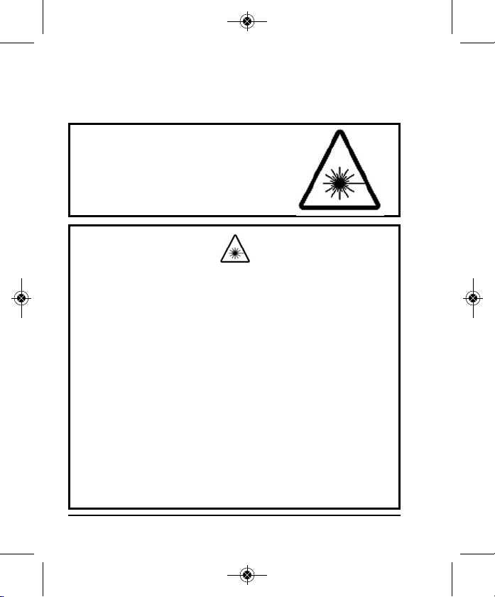
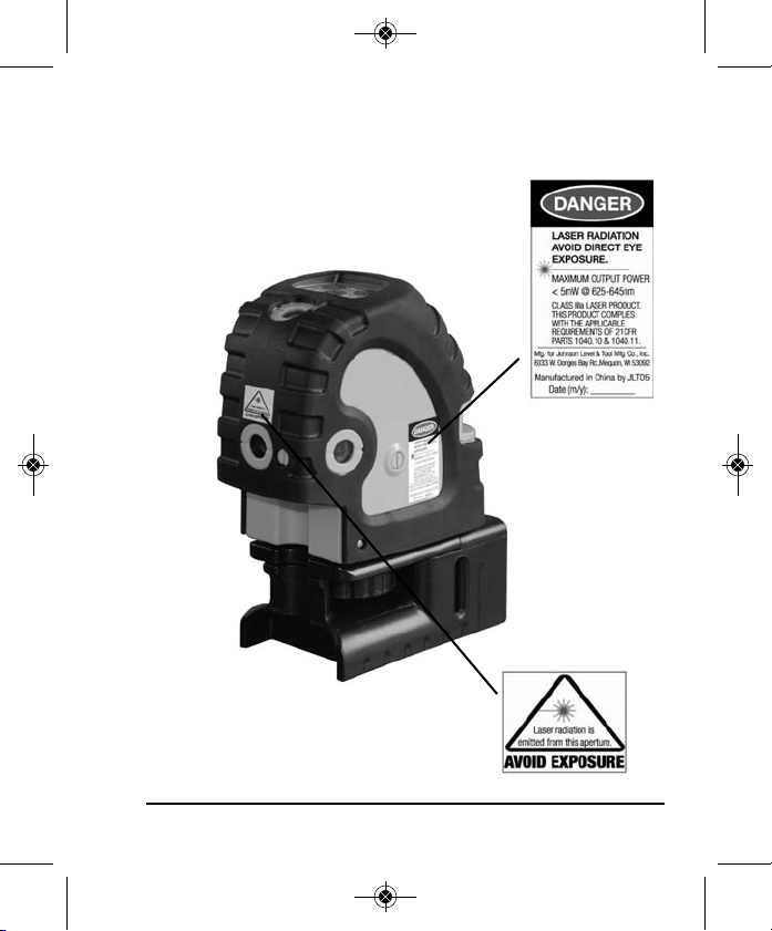
DANGER!
Class IIIa Laser Product
Max. Power Output: ≤ 5mW
Wavelength: 625-645nm
THIS TOOL EMITS LASER RADIATION.
DO NOT STARE INTO BEAM.
AVOID DIRECT EYE EXPOSURE.
ATTENTION IMPORTANT
• Read all instructions prior to operating this laser tool. Do not remove any labels from tool.
• Do not stare directly at the laser beam.
• Do not project the laser beam directly into the eyes of others.
• Do not set up laser tool at eye level or operate the tool near a reflective surface as
the laser beam could be projected into your eyes or into the eyes of others.
• Do not place the laser tool in a manner that may cause someone to unintentionally
look into the laser beam. Serious eye injury may result.
• Do not operate the tool in explosive environments, i.e. in the presence of gases or
flammable liquids.
• Keep the laser tool out of the reach of children and other untrained persons.
• Do not attempt to view the laser beam through optical tools such as telescopes as
serious eye injury may result.
• Always turn the laser tool off when not in use or left unattended for a period of time.
• Remove the batteries when storing the tool for an extended time (more than 3 months)
to avoid damage to the tool should the batteries deteriorate.
• Do not attempt to repair or disassemble the laser tool. If unqualified persons attempt
to repair this tool, warranty will be void.
• Use only original Johnson
authorized dealer. Use of non-Johnson®parts and accessories will void warranty.
®
parts and accessories purchased from your Johnson
®
4 ©2012 Johnson Level & Tool
Page 5
6339H_Manuals 10/24/12 12:56 PM Page 5
4. Location/Content of Warning Labels
©2012 Johnson Level & Tool 5
Page 6
6339H_Manuals 10/24/12 12:56 PM Page 6
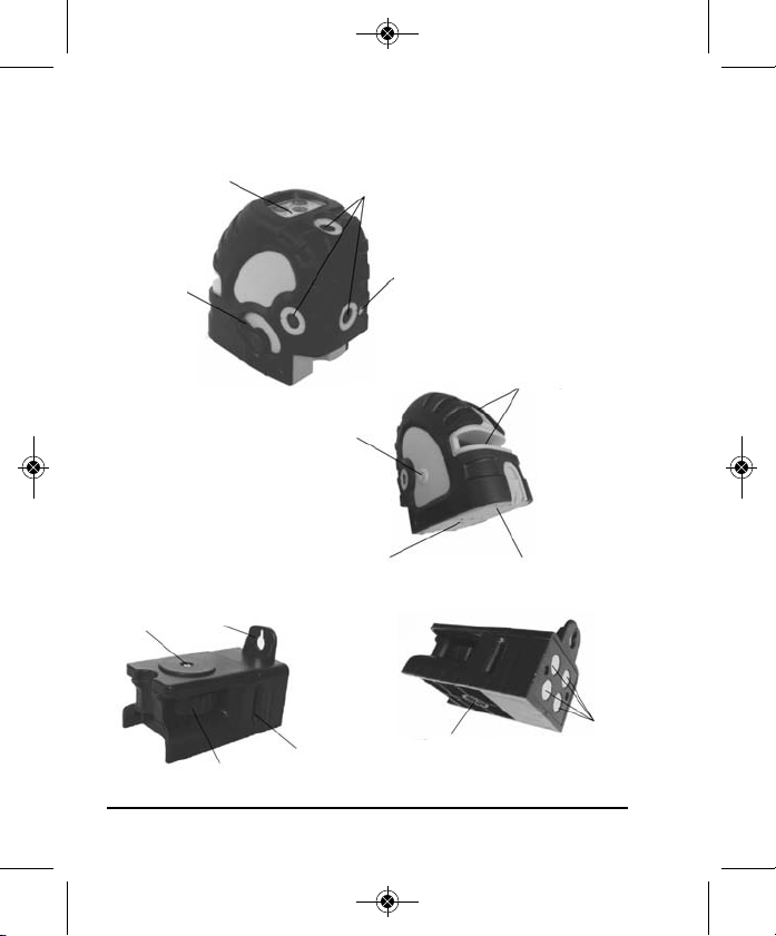
5. Location of Part/Components
Keypad
Compensator
Lock/Unlock
Switch
Self-calibration Aperture B
1/4” - 20
Thread
attaches
to base
Laser Connecting Knob
Wall Mount
Laser Dot Output Windows
1/4” - 20 Thread
Belt Mounting
Groove
Self-calibration Aperture A
Laser Line
Output Windows
Battery Cover
5/8” Thread
Rare Earth
Magnets
6 ©2012 Johnson Level & Tool
Page 7
6339H_Manuals 10/24/12 12:56 PM Page 7
6. Operating Instructions
IMPORTANT: It is the responsibility of the user to verify the
calibration of the instrument before each use.
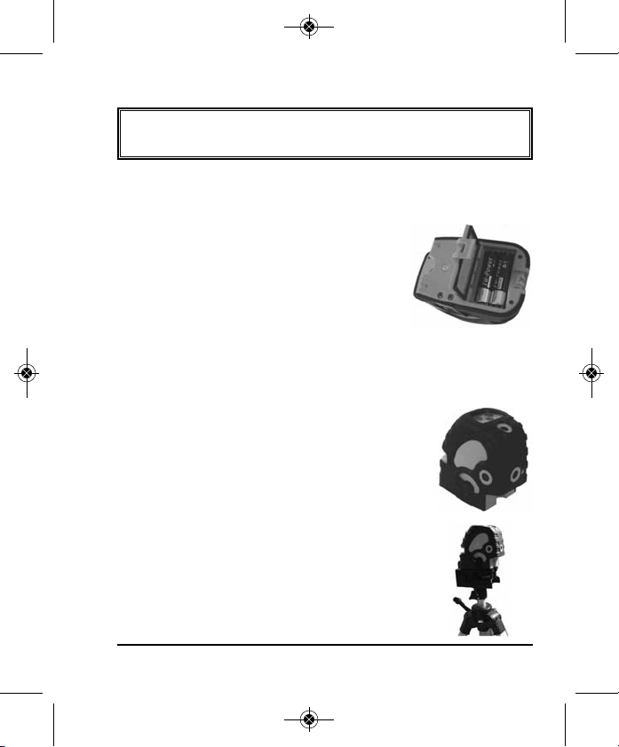
Battery Installation
Note:
Always check to be sure that the compensator lock/unlock switch
is in the locked position before removing and replacing batteries.
1. As shown in figure, open the battery cover.
2. Put three “AA” alkaline batteries into the
battery compartment noting polarity
3. Close the battery cover.
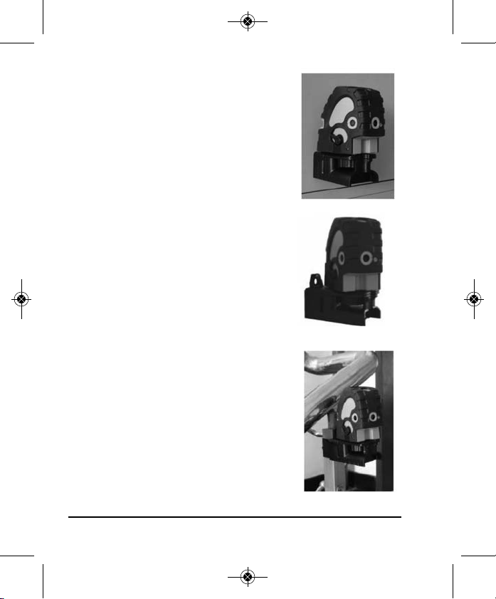
7. Using the Product
Place the laser on a relatively smooth, flat and
level surface.
Note: Product must be within ±4º of level for
self-leveling feature to function properly. Greater
than 4º will result in an alarm condition (flashing
laser and intermittent beeping sound).
Place the laser on a tripod using the multi-functional
base.
©2012 Johnson Level & Tool 7
Page 8
6339H_Manuals 10/24/12 12:56 PM Page 8
Attach the laser to a steel object.
Laser can pivot on base.
Strap the laser to a pole.
8 ©2012 Johnson Level & Tool
Page 9
6339H_Manuals 10/24/12 12:56 PM Page 9
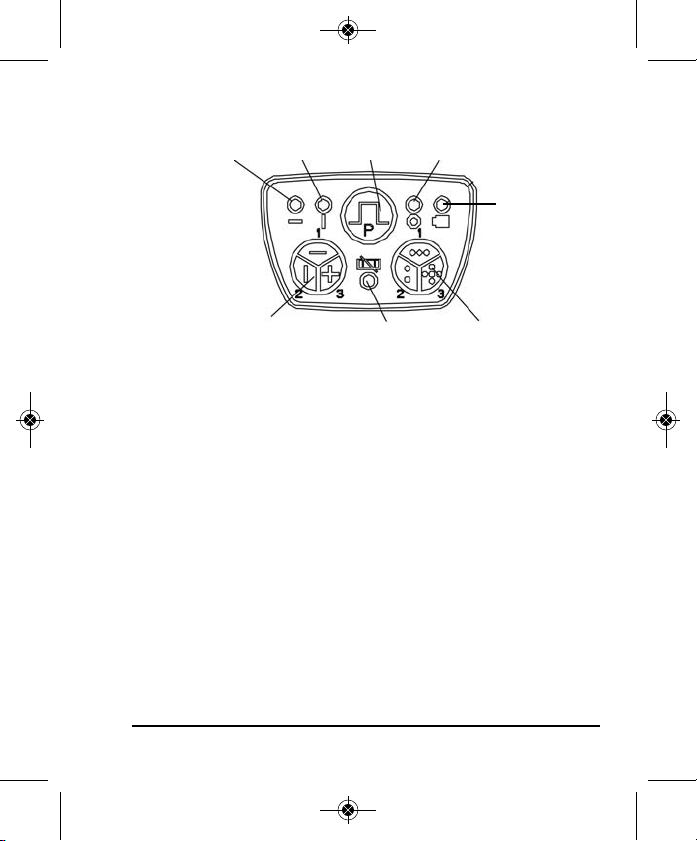
Keypad Operations
Horizontal Line
LED
Laser Line Control Button
Vertical
Line LED
Pulse Mode
Button
Manual Mode LED
Dot LED /
Out-of-Level LED
(when flashing)
Power LED
Laser Dot
Control Button
Power LED:
LED On: Laser is on or pendulum compensator is unlocked
LED Off: Pendulum compensator is locked and laser is off
LED Flashing: Low Battery
Manual Mode LED:
LED Flashing: The pendulum compensator is locked (laser is not
self-leveling) and laser is on
LED Off: The laser is in self-leveling mode or the laser is off
Horizontal Laser Line LED:
LED On: The horizontal laser line is on
LED Flashing: The horizontal laser line is in pulse mode and can be
used with a line detector (40-6780)
LED Off: The horizontal laser line is off
©2012 Johnson Level & Tool 9
Page 10

6339H_Manuals 10/24/12 12:56 PM Page 10
Vertical Laser Line LED:
LED On: The vertical laser line is on
LED Flashing: The vertical laser line is in pulse mode and can be
used with a line detector (40-6780)
LED Off: The vertical laser line is off
Dot LED:
LED On: Dot laser is on
LED Off: Dot laser is off
LED Flashing: Laser is outside its self-leveling range
Pendulum Compensator Lock Switch
Unlock the laser, the laser will be on, and the power LED is on. Lock
the laser, the laser will be off, and the power LED is off.
Locked Position Unlocked Position
When unlocking the laser, if the laser flashes and sounds an alarm,
the laser is out of its self-leveling range.
10 ©2012 Johnson Level & Tool
Page 11

6339H_Manuals 10/24/12 12:56 PM Page 11
Pulse Mode Button
When the horizontal laser line, vertical laser line, or both laser lines
are on, press the pulse button and the laser line will enter Pulse
Mode and the corresponding LED will flash. Press the pulse
button again and the laser will exit the pulse mode, and the
corresponding LED will return to solid.
Note:
1. When the laser lines are off, the pulse mode button will not
function.
2. Pulse mode is for use with a detector.
Laser Line Control Button
Press the line button to turn the laser line
on or off. Unlock the laser and press the line
button once. The horizontal laser line
LED will be on and the output of the laser is
as follows:
Press the line button a second time, the
horizontal laser line LED will be off, the vertical
LED will be on, and the output of the laser is
as follows:
Horizontal Line
Vertical Line
©2012 Johnson Level & Tool 11
Page 12

6339H_Manuals 10/24/12 12:56 PM Page 12
Press the line button a third time, the
horizontal laser line and vertical laser line LED
will be on, and the output of the laser is as follows:
Cross-Line
Press the line button a fourth time, the horizontal laser line and
vertical laser line LED will be off, there is no laser line output.
Laser Dot Control Button
Press the dot button to turn the laser dot on
or off, unlock the laser and press the dot
button once. The Laser Dot LED is on and the
output of the laser is as follows:
Press the dot button a second time, the
Laser Dot LED is on, the output of the laser is as
follows:
3 Dots
2 Dots
12 ©2012 Johnson Level & Tool
Page 13

6339H_Manuals 10/24/12 12:56 PM Page 13
Press the dot button a third time, the Laser
Dot LED is on, the output of the laser is as
follows:
Press the dot button a fourth time, the Laser Dot LED is off, there
is no laser dot output.
With all laser lines and laser dots being on the
laser, the output is as follows:
Manual Mode
With the lasers compensator pendulum switch locked, press the
button or the button, the laser will be in manual mode, the power
LED is on, and the manual mode LED will be flashing.
Note:
1. When manual mode is on, the laser does not self-level and no
out-of-level alarm is indicated.
2. If the lasers compensator pendulum switch is unlocked during
manual mode, the laser will go into self-leveling mode and the
manual mode LED will turn off.
5 Dots
Cross-Line and 5 Dots
©2012 Johnson Level & Tool 13
Page 14

6339H_Manuals 10/24/12 12:56 PM Page 14
Detector Usage (included in Model No. 40-6687)
1. Detector Technical Specifications
Detecting Accuracy: 0.019” ≤ 50 ft. (0.5mm ≤ 15m)
0.039” ≤ 100 ft. (1mm ≤ 35m)
0.059” ≥ 100 ft. (1.5mm ≥ 35m)
Automatic Shut-off: 6 minutes
Power Supply: 9V battery
Sound Indicator: fast tone, double tone and solid tone
LCD: Up arrow, Down arrow, Center sign
LED Indication: Up, Middle, Down
Dimensions: 5.905" x 2.992" x 1.142" (150 x 76 x 29mm)
Weight: 0.386 lb. (0.175kg)
Others: Rain and dust resistant
2. Components
With this laser detector, a line generated pulsed Johnson®laser can
be used both indoors with bright light and/or outdoors in the
sunlight where the beams are not visible.
14 ©2012 Johnson Level & Tool
Page 15

6339H_Manuals 10/24/12 12:56 PM Page 15
1. Horizontal Vial
2. Reception Window
3. Sound On/Off Key
4. Power On/Off Key
5. Vertical Vial
6. Display Window
7. Front On Grade Mark
8. Beeper
9. Top Indicator Light
10. Middle Indicator Light
11. Bottom Indicator Light
12. Rear On Grade Mark
13. Rod Bracket Thread
14. Battery Door
Display Window Symbols
1. Power On
2. Low Voltage
3. Coarse/Fine
4. Sound On
5. Position Indication Arrows
©2012 Johnson Level & Tool 15
Page 16

6339H_Manuals 10/24/12 12:56 PM Page 16
3. Operation Instructions
1. Battery Installation
Open the battery door, and put in one 9V battery according to the
polarity shown inside. Then snap the battery door
back.
Note:
• Remove the battery when the unit is being
stored for a long time.
• Replace the battery when the low voltage
indicator shows a low battery.
2. Operating Instructions
IMPORTANT: This detector will only work when the laser is in
the pulse mode.
A. Press the Power on/off key: The detector
will beep twice and all the symbols will be
displayed on the display window. After
0.5 seconds the detector will enter its
detecting mode.
B. Detecting the horizontal laser signal: Put
the detector in a vertical position and center
the bubble in the horizontal vial with the
reception window facing the laser. A down
arrow shown on the display window and a lit
red light indicates the laser signal is below the detectors on grade
16 ©2012 Johnson Level & Tool
Page 17

6339H_Manuals 10/24/12 12:56 PM Page 17
mark. An up arrow plus a yellow lit light indicates the laser signal is
above the detectors on grade mark. A middle sign plus a lit green light
indicates the laser signal is on grade.
Note: When the laser signal moves towards the
center position, the displayed up or down
arrows will decrease in size, until the center
single line appears.
C. Detecting the vertical laser signal: Put the
detector in a horizontal position (center the bubble
in the horizontal vial) with the reception window
and indicator lights facing up. Have the reception
window face the unit to receive the vertical laser
signal. Left arrow shown on LCD plus a lit red light
indicates the laser signal is on the left side of center.
A middle sign with a lit green light indicates the
laser signal is on the middle position. A right arrow plus a lit
yellow light indicates the laser signal is on the right side of center.
D. Press the Power on/off key to power off the detector. The
detector will beep twice for off.
3. Sound Function
Pressing the sound key when the unit
is powered-on. This will switch the
unit between sound on and sound off,
Sound
On
Sound
Off
note the sound sign indication on LCD.
©2012 Johnson Level & Tool 17
Page 18

6339H_Manuals 10/24/12 12:56 PM Page 18
Sound function on:
• If the laser signal is on the top (left) side, then the detector will
give a fast tone.
• If the laser signal is on the bottom (right) side, then the detector
will give a double tone.
• If the laser signal is on the middle, then the detector will have a
solid tone.
4. Automatic Shut-Off Function
When not receiving a laser signal and with no operation of the keys
for six continuous minutes, the unit will power off automatically to
preserve battery life.
5. Low Battery Indicator Function
• When the power indicator sign is blinking, it
indicates that the battery is low and should
be replaced.
• A very low battery will result in an automatic
power-off, which requires the user to
replace before continued operation.
Blink
18 ©2012 Johnson Level & Tool
Page 19

6339H_Manuals 10/24/12 12:56 PM Page 19
8. Self-Check & Fine Calibration
IMPORTANT: It is the responsibility of the user to verify the
calibration of the instrument before each use.
Horizontal line accuracy (horizontal)
1. Place unit on a tripod approximately 5m from a wall. Secure the
instrument on the tripod.
2. Face the front of the instrument to the wall, unlock the
instrument, and power on the horizontal and vertical laser lines.
Make a mark on the wall where the cross-line is displayed. Label
this as ‘A’.
3. Make a mark 2.5m from A, along the horizontal laser line, and
label as ‘M’.
4. Turn the instrument until the vertical line meets ‘M’, and then
make a mark 2.5m from ‘M’, and 5m from ‘A’. Label this mark as
‘B’. Also make a mark on the vertical line where it meets ‘B’.
5. Measure the height distance between ‘M’ and where the
horizontal laser line currently sits.
6. If e>1mm, the instrument accuracy is out of tolerance, and calibration is necessary.
Horizontal accuracy self-check (Vertical)
1. Stand up two straight poles/boards 5m from each other, or two
walls which are parallel and more than 5m distance.
2. Place the instrument on the tripod, and place in the center of
the poles/boards/walls, and level the instrument by adjusting
the tripod.
©2012 Johnson Level & Tool 19
Page 20
6339H_Manuals 10/24/12 12:56 PM Page 20
3. Power on horizontal and vertical laser lines, and make a mark
where the cross laser meets target ‘A’. Mark this as ‘A1’.
4. Turn the instrument by 180°, so that the cross line meets target
‘B’. Mark this as ‘B1’.
5. Move the tripod within .6m of target ‘A’. Make a mark where the
cross meets target ‘A’, and label as ‘A2’.
6. Rotate the instrument by 180° and make a mark where the cross
meets target ‘B’, and label as ‘B2’.
7. Calculate (A1-A2)-(B1-B2) = E. If the absolute value of E is above
1mm, the instrument accuracy is out of tolerance and calibration
is required.
Self-check and Calibration
The instrument has two calibration apertures. Aperture ‘A’ adjusts
the horizontal axis. Aperture ‘B’ adjusts the Vertical axis
Notes regarding adjustment:
1. Use a 3mm Hexagon tool for adjustment.
2. The adjustment of each axis may influence the other. When
making fine adjustments in the left/right direction horizontally, the
front and back direction vertically may change. When adjusting
the front/back direction vertically, the left and right direction will
possibly change. Adjustments may need to be checked and
repeated alternately.
3. The adjustment of the self calibration screw cannot exceed 4
turns in either direction.
4. If the instrument accuracy cannot be adjusted through self
calibration, please contact an authorized repair facility, or contact
Johnson Level & Tool.
20 ©2012 Johnson Level & Tool
Page 21

6339H_Manuals 10/24/12 12:56 PM Page 21
Dot Accuracy
1. With the laser on its base and set on a flat platform, turn the
laser on.
2. Mark the down beam location and use this as your reference
point.
3. Locate the up beam and mark its point as ‘A’.
4. Rotate the laser (not moving the base) 180° by swiveling the laser
on its base and mark the up beam location as ‘B’.
5. Rotate the laser 90° and mark the up beam as ‘C’.
6. Rotate the laser 180° and mark the up beam as ‘D’.
Note: Do not move the base, and always have the down beam in
the same location.
7. Connect the four dots. Connect A to B, and C to D.
8. If the center point ‘E’ is more than 1/8” at 50’, or 1/32” at 24.5’
from points A,B, C, and D, the unit needs to be recalibrated.
Fine Calibration
1. Remove plastic screws on front and left of the laser.
2. With the unit on its base, and on a flat surface, turn the laser on.
3. Return the laser back to its original starting point from the self
check.
4. Use a 2mm allen wrench to turn the front adjusting screw to
position the laser beam forward and backward.
5. Use the side adjusting screw to position the laser beam left
and right.
6. Move the top beam to the intersection of the 4 dots.
©2012 Johnson Level & Tool 21
Page 22

6339H_Manuals 10/24/12 12:56 PM Page 22
7. Perform another self check calibration as described previously to
make sure the laser is calibrated.
8. If the laser is still beyond its accuracy specification, recalibrate the
laser again.
9. If laser is still out of calibration, contact Johnson Level & Tool for
service.
10. Return the plastic screws, being careful not to over-tighten.
Self-checking the 3 Horizontal Beams
1. As shown in Fig. 1, set the instrument on a tripod or flat platform
50’ from an upright wall. Aim the front beam at the face of the
wall. Mark the point projected on the wall by front beam as ‘A’.
2. Turn the instrument clockwise (Fig. 2) to make the point
projected by the right laser beam on the same exact line as point
‘A’, and then mark the point as ‘B’.
3. Turn the instrument clockwise (Fig. 3) to make the point
projected by the left laser beam on the same exact line as point
‘A’, and then mark the point as ‘C’.
4. The vertical distance between points A, B and C should not
exceed 0.125” (3.2mm).
5. If laser exceeds 1/8” at 50’, contact Johnson Level & Tool for
service.
Fig. 1 Fig. 2
Fig. 3
22 ©2012 Johnson Level & Tool
Page 23

6339H_Manuals 10/24/12 12:56 PM Page 23
9. Technical Specifications
Laser Wavelength 635nm±10
Laser Classification Class IIIa
Maximum Power Output ≤5mW
Accuracy ±1/8"/50 ft. (±1mm/10m)
Interior Range Up to 150 ft. (45m) for lines depending
Exterior Range Up to 300 ft. (90m) with detector
Self-Leveling Range ±4°
Power Supply 3 “AA” alkaline batteries (included)
Battery Life Approx. battery life 20 hours continuous use
Dimensions 4.803" x 2.835" x 4.567"
Weight 5.164 lbs. (0.6 Kg)
Working Temperature 14° F to 113° F (-10° C to +45° C)
Center Screw Thread 5/8" – 11; 1/4" – 20
IP Protection 54
upon light conditions
Up to 200 ft. (60m) for dots depending
upon light conditions
(included with 40-6687)
(122 x 72 x 116mm)
©2012 Johnson Level & Tool 23
Page 24

6339H_Manuals 10/24/12 12:56 PM Page 24
10. Application Demonstrations
Reference for baseboard installation Reference for vertical partition
Aligning doors and windows Reference for fence installation
24 ©2012 Johnson Level & Tool
Page 25

6339H_Manuals 10/24/12 12:56 PM Page 25
11. Care and Handling
• This laser unit is a precision tool that must be handled with care.
• Avoid exposing unit to shock vibrations and extreme temperatures.
• Before moving or transporting the unit, make sure that the unit is turned off.
• Remove the batteries when storing the unit for an extended time (more than
three months) to avoid damage to the unit should the batteries deteriorate.
• Always store the unit in its case when not in use.
• Avoid getting the unit wet.
• Keep the laser unit dry and clean, especially the laser output window.
Remove any moisture or dirt with a soft, dry cloth.
• Do not use harsh chemicals, strong detergents or cleaning solvents to clean
the laser unit.
12. Product Warranty
Johnson Level & Tool offers a three year limited warranty on each of its products.
You can obtain a copy of the limited warranty for a Johnson Level & Tool
product by contacting Johnson Level & Tool's Customer Service Department,
as provided below, or by visiting our web site at www.johnsonlevel.com. The
limited warranty for each product contains various limitations and exclusions.
Do not return this product to the store/retailer or place of purchase.
Non-warranty repairs and course calibration must be done by an authorized
Johnson®service center or Johnson Level & Tool's limited warranty, if
applicable, will be void and there will be NO WARRANTY. Contact one of our
service centers for all non-warranty repairs. A list of service centers can be
found on our web site at www.johnsonlevel.com or by calling our Customer
Service Department. Contact our Customer Service Department for Return
Material Authorization (RMA) for warranty repairs (manufacturing defects
only). Proof of purchase is required.
©2012 Johnson Level & Tool 25
Page 26

6339H_Manuals 10/24/12 12:56 PM Page 26
NOTE: The user is responsible for the proper use and care of the product. It is the
responsibility of the user to verify the calibration of the instrument before each use.
For further assistance, or if you experience problems with this product that are not
addressed in this instruction manual, please contact our Customer Service Dept.
In the U.S., contact Johnson Level & Tool’s Customer Service Department at
888-9-LEVELS.
In Canada, contact Johnson Level & Tool’s Customer Service Department at
800-346-6682.
13. Warranty Registration
Enclosed with this instruction manual you will find a warranty
registration card to be completed for your product. You will need to
locate the serial number for your product that is located on the bottom
of the unit. PLEASE NOTE THAT IN ADDITION TO ANY OTHER
LIMITATIONS OR CONDITIONS OF JOHNSON LEVEL & TOOL'S
LIMITED WARRANTY, JOHNSON LEVEL & TOOL MUST HAVE
RECEIVED YOUR PROPERLY COMPLETED WARRANTY CARD AND
PROOF OF PURCHASE WITHIN 30 DAYS OF YOUR PURCHASE OF
THE PRODUCT OR ANY LIMITED WARRANTY THAT MAY APPLY
SHALL NOT APPLY AND THERE SHALL BE NO WARRANTY.
26 ©2012 Johnson Level & Tool
Page 27

6339H_Manuals 10/24/12 12:56 PM Page 27
14. Accessories
Johnson®accessories are available for purchase through authorized
®
Johnson
applicable limited warranty and there will be NO WARRANTY. If you need
any assistance in locating any accessories, please contact our
Customer Service Department.
In the U.S., contact Johnson Level & Tool’s Customer Service
Department at 888-9-LEVELS.
In Canada, contact Johnson Level & Tool’s Customer Service
Department at 800-346-6682.
dealers. Use of non-Johnson®accessories will void any
©2012 Johnson Level & Tool 27
Page 28

6339H_Manuals 10/24/12 12:56 PM Page 28
28 ©2012 Johnson Level & Tool
 Loading...