

Page 1
6222H_Manuals 10/2/12 8:54 AM Page 1
Self-Leveling 3 Line or 3 Dot Laser
Model No. 40-6683
Instruction Manual
Congratulations on your choice of this Self-Leveling 3 Line or 3 Dot
Laser. We suggest you read this instruction manual thoroughly before
using the instrument. Save this instruction manual for future use.
This is a Class IIIa laser tool and is manufactured to comply with
CFR 21, parts 1040 .10 and 1040 .11 as well as international safety
rule IEC 285.
©2012 Johnson Level & Tool 1
Page 2
6222H_Manuals 10/2/12 8:54 AM Page 2
Table of Contents
1. Kit Contents
2. Features and Functions
3. Safety Instructions
4. Location/Content
of Warning Labels
5. Location of Parts/Components
6. Operating Instructions
7. Using the Product
8. Self-Check & Fine Calibration
9. Technical Specifications
10. Application Demonstrations
11. Care and Handling
12. Product Warranty
13. Warranty Registration
14. Accessories
1. Kit Contents
Description for Model 40-6683 Qty.
Self-Leveling 3 Line or 3 Dot Laser 1
Multi-Functional Magnetic Base 1
“AA” Alkaline Batteries 3
Tinted Glasses 1
Mounting Strap 1
Magnetic Target 1
Instruction Manual with Warranty Card 1
Hard-Shell Carrying Case 1
2 ©2012 Johnson Level & Tool
Page 3
6222H_Manuals 10/2/12 8:54 AM Page 3
2. Features and Functions
• Able to project three lines with two cross-line beams,
consisting of two horizontal lines and one vertical line with a
plumb down laser dot.
• Product simultaneously projects three laser beams (front, up
and down).
• Magnetic dampening compensation system.
• Laser flashes/sounds audible alarm when beyond leveling
range.
• Manual mode feature allows unit to be tipped at extreme
angles without the audible alarm and laser flash being
triggered
• Multi-functional magnetic base is included to allow
hanging on wall, attach to metal, or connect to tripod
(5/8"-11).
• Includes adjustable strap for attachment to pipe or conduit.
• Pendulum locking mechanism helps protect units inner
mechanisms.
©2012 Johnson Level & Tool 3
Page 4
6222H_Manuals 10/2/12 8:54 AM Page 4
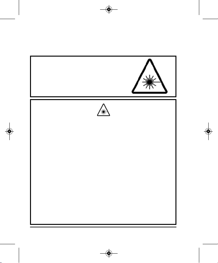
3. Safety Instructions
Please read and understand all of the following instructions, prior
to using this tool. Failure to do so, may void the warranty.
DANGER!
Class IIIa Laser Product
Max. Power Output: ≤ 5mW
Wavelength: 625-645nm
THIS TOOL EMITS LASER RADIATION.
DO NOT STARE INTO BEAM.
AVOID DIRECT EYE EXPOSURE.
ATTENTION IMPORTANT
• Read all instructions prior to operating this laser tool. Do not remove any labels from tool.
• Do not stare directly at the laser beam.
• Do not project the laser beam directly into the eyes of others.
• Do not set up laser tool at eye level or operate the tool near a reflective surface as
the laser beam could be projected into your eyes or into the eyes of others.
• Do not place the laser tool in a manner that may cause someone to unintentionally
look into the laser beam. Serious eye injury may result.
• Do not operate the tool in explosive environments, i.e. in the presence of gases or
flammable liquids.
• Keep the laser tool out of the reach of children and other untrained persons.
• Do not attempt to view the laser beam through optical tools such as telescopes as
serious eye injury may result.
• Always turn the laser tool off when not in use or left unattended for a period of time.
• Remove the batteries when storing the tool for an extended time (more than 3 months)
to avoid damage to the tool should the batteries deteriorate.
• Do not attempt to repair or disassemble the laser tool. If unqualified persons attempt
to repair this tool, warranty will be void.
• Use only original Johnson
authorized dealer. Use of non-Johnson®parts and accessories will void warranty.
®
parts and accessories purchased from your Johnson
®
4 ©2012 Johnson Level & Tool
Page 5
6222H_Manuals 10/2/12 8:54 AM Page 5
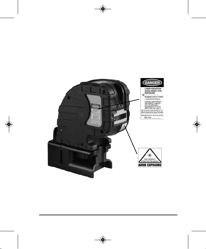
4. Location/Content of Warning Labels
©2012 Johnson Level & Tool 5
Page 6
6222H_Manuals 10/2/12 8:54 AM Page 6
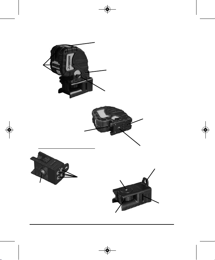
5. Location of Part/Components
Keypad
Laser
Output
Windows
Self-calibration
Apertures
(side & back)
Compensator
Lock and
On/Off Switch
Down
Laser/Dot
Output Window
Multi-Functional Magnetic Base
Magnets
5/8 Screw Thread
6 ©2012 Johnson Level & Tool
1/4 -20 Thread
Instrument
Connecting Knob
Battery Cover
1/4 -20 Thread
Wall Mount
Belt Mounting
Groove
Page 7

6222H_Manuals 10/2/12 8:54 AM Page 7
6. Operating Instructions
IMPORTANT: It is the responsibility of the user to verify the
calibration of the instrument before each use.
Alkaline Battery Installation
Note: Always check to be sure that the on/off switch is in the off
position before removing and replacing batteries.
1. As shown in figure, put 3 “AA” alkaline batteries into the battery
compartment noting the polarity as shown in the battery
compartment. Snap the battery cover shut. Turn the on/off
switch to on. If the power LED is flashing, the battery is low.
©2012 Johnson Level & Tool 7
Page 8

6222H_Manuals 10/2/12 8:54 AM Page 8
7. Using the Product
This base was specially designed for more extensive adaptability of
the laser. The base can be connected to a standard 5/8"-11 tripod.
The laser can be connected to a 1/4" – 20 tripod. With the use of the
base, the laser can be rotated, hung on a wall, attached to a metal
plate, or strapped to a column or pipe.
1. Install the laser on the base by rotating the connecting knob
counter-clockwise.
2. The laser can be rotated on the base.
3. The laser can be hung on a wall with a nail or screw.
Operating Instructions
Horizontal Line,
Vertical Line,
Manual Mode
Control Button
Power LED
Manual Mode LED
Dot or Line
Control Button
Power LED
LED is on: power is on
LED is off: power is off
LED is flashing: low voltage
8 ©2012 Johnson Level & Tool
Page 9

6222H_Manuals 10/2/12 8:54 AM Page 9
Manual Mode LED
LED is flashing: the laser is in manual mode
LED is off: the laser is in self-leveling mode
Power On/Off
Unlock the laser by rotating the compensator lock and on/off switch
from the off (down) position to the on (up) position as shown
below, the laser is on, and the power LED is on.
Lock the laser by rotating the switch to the off (down) position, the
laser is off, and the power LED is off.
Locked Unlocked
Note: Product must be within ± 3° of level for self-leveling feature
to function properly. Greater than ± 3° will result in an alarm
condition (flashing laser and intermittent beeping sound).
©2012 Johnson Level & Tool 9
Page 10

6222H_Manuals 10/2/12 8:54 AM Page 10
Beam Configurations
Unlock the laser and the laser is on, the
configuration of the laser beams is as
follows:
Press the button once and the vertical line
is off, the configuration of the laser beams is
as follows:
Press the button once again and the
horizontal lines are off and the vertical line
is on, the configuration of the laser beams is
as follows:
Press the button once again, both
horizontal lines and the vertical line will be
off, there are no laser beams.
Press the button, the laser will produce
three laser dots (front, up and down dot).
Press the button again, the laser will switch to line laser mode.
The button controls switching between the laser line and
laser dot modes.
10 ©2012 Johnson Level & Tool
Page 11

6222H_Manuals 10/2/12 8:54 AM Page 11
Manual Mode
With the laser in the locked position, press the button and the
laser will be in manual mode. The power LED is on and the
manual mode LED is flashing.
When the laser is in manual mode, the dot and line control buttons
are used as per the above descriptions.
When pressing the button four times, all the laser lines will be
off, one more press of the button will turn the manual mode
off. The manual LED is off, the power LED is off and the laser is off.
Note: When the Manual Mode feature is engaged, the self-leveling
alarm is deactivated. If the laser is unlocked, it can not enter manual
mode, if the laser is in the manual mode, and unlocked, the laser will
exit the manual mode (manual LED is off) and the laser will enter the
self-leveling mode.
©2012 Johnson Level & Tool 11
Page 12

6222H_Manuals 10/2/12 8:54 AM Page 12
8. Self-Check & Fine Calibration
IMPORTANT: It is the responsibility of the user to verify the
calibration of the instrument before each use.
Horizontal Line Accuracy (Horizontal)
1. Place the unit on a tripod approximately 5m from a wall.
Secure the laser on the tripod and level the unit.
2. Face the front of the laser to the wall, unlock the laser, and
power on the laser lines. Make a mark on the wall where the
cross-line is displayed. Label this as “A”.
3. Make a mark 2.5m from “A”, along the horizontal laser line,
and label as “M”.
4. Turn the laser until the vertical line meets “M”, and then make a
mark 2.5m from “M”, and 5m from “A”. Label this mark “B”.
Also make a mark on the vertical line where it meets “B”.
5. Measure the height distance between “M” and where the
horizontal laser line currently sits.
6. If e>1mm, the laser accuracy is out of tolerance, and
calibration is necessary.
Horizontal Accuracy Self-Check (Vertical)
1. Stand up two straight poles/boards 5m from each other, or two
walls which are parallel and more than 5m distance.
2. Place the laser on the tripod, and place in the center of the
poles/boards/walls, and level the laser by adjusting the tripod.
3. Power on all laser lines, and make a mark where the cross
laser meets target “A”. Mark this as “A1”.
4. Turn the instrument 180º, so that the cross line meets target
“B”. Mark this as “B1”.
12 ©2012 Johnson Level & Tool
Page 13

6222H_Manuals 10/2/12 8:54 AM Page 13
5. Move the tripod within .6m of target “A”. Make a mark where
the cross meets target “A” and label as “A2”.
6. Rotate the laser 180º and make a mark where the cross
meets target “B” and label as “B2”.
7. Calculate (A1-A2) - (B1-B2) = E. If the absolute value of E is
above 1mm, the laser accuracy is out of tolerance and
calibration is required.
Self-Check and Calibration
The instrument has two calibration apertures. Aperture “A” adjusts
the horizontal axis. Aperture “B” adjusts the vertical axis.
Notes regarding adjustment:
• Use a 3mm hexagon tool for adjustment.
• The adjustment of each axis may influence the other. When
making fine adjustments in the left/right direction horizontally,
the front and back direction vertically may change. When
adjusting the front/back direction vertically, the left and right
direction will possibly change. Adjustments may need to be
checked and repeated alternately.
• The adjustment of the self-calibration screw cannot exceed
four turns in either direction.
• If the laser accuracy cannot be adjusted through self-calibration,
please contact an authorized repair facility, or contact Johnson
Level & Tool.
©2012 Johnson Level & Tool 13
Page 14

6222H_Manuals 10/2/12 8:54 AM Page 14
9. Technical Specifications
Laser Wavelength 635nm±10
Laser Classification Class IIIa
Maximum Power Output ≤5mW
Accuracy ±1/8"/50 ft. (±2mm/10m)
Interior Range Up to 150 ft. (45m) for lines depending
upon light conditions
Up to 200 ft. (120m) for dots depending
upon light conditions
Self-Leveling Range ± 3°
Power Supply 3 “AA” alkaline batteries (included)
Battery Life Approx. battery life 15 hours continuous use
Dimensions 5.31” x 4.84” x 2.56”
(135 x 123 x 65mm)
Weight 1.869 lbs. (0.7 Kg)
Working Temperature 14°F to 113°F (-10°C to +45°C)
Center Screw Thread 1/4” - 20 on laser
5/8” - 11 on base
IP Protection Class 54
14 ©2012 Johnson Level & Tool
Page 15

6222H_Manuals 10/2/12 8:54 AM Page 15
10. Application Demonstrations
Plumb reference for lamp installation
Reference for pipeline installation
Reference for door frame installation
Reference for vertical partition
©2012 Johnson Level & Tool 15
Reference for fence installation
Reference for dormer installation
Reference for construction cubic partition
Page 16

6222H_Manuals 10/2/12 8:54 AM Page 16
11. Care and Handling
• This laser unit is a precision tool that must be handled with care.
• Avoid exposing unit to shock vibrations and extreme temperatures.
• Before moving or transporting the unit, make sure that the unit is turned off.
• Remove the batteries when storing the unit for an extended time (more than
three months) to avoid damage to the unit should the batteries deteriorate.
• Always store the unit in its case when not in use.
• Avoid getting the unit wet.
• Keep the laser unit dry and clean, especially the laser output window.
Remove any moisture or dirt with a soft, dry cloth.
• Do not use harsh chemicals, strong detergents or cleaning solvents to clean
the laser unit.
12. Product Warranty
Johnson Level & Tool offers a three year limited warranty on each of its products.
You can obtain a copy of the limited warranty for a Johnson Level & Tool
product by contacting Johnson Level & Tool's Customer Service Department,
as provided below, or by visiting our web site at www.johnsonlevel.com. The
limited warranty for each product contains various limitations and exclusions.
Do not return this product to the store/retailer or place of purchase.
Non-warranty repairs and course calibration must be done by an authorized
Johnson®service center or Johnson Level & Tool's limited warranty, if
applicable, will be void and there will be NO WARRANTY. Contact one of our
service centers for all non-warranty repairs. A list of service centers can be
found on our web site at www.johnsonlevel.com or by calling our Customer
Service Department. Contact our Customer Service Department for Return
Material Authorization (RMA) for warranty repairs (manufacturing defects
only). Proof of purchase is required.
16 ©2012 Johnson Level & Tool
Page 17

6222H_Manuals 10/2/12 8:54 AM Page 17
NOTE: The user is responsible for the proper use and care of the product. It is the
responsibility of the user to verify the calibration of the instrument before each use.
For further assistance, or if you experience problems with this product that are not
addressed in this instruction manual, please contact our Customer Service Dept.
In the U.S., contact Johnson Level & Tool’s Customer Service Department at
888-9-LEVELS.
In Canada, contact Johnson Level & Tool’s Customer Service Department at
800-346-6682.
13. Warranty Registration
Enclosed with this instruction manual you will find a warranty
registration card to be completed for your product. You will need to
locate the serial number for your product that is located on the bottom
of the unit. PLEASE NOTE THAT IN ADDITION TO ANY OTHER
LIMITATIONS OR CONDITIONS OF JOHNSON LEVEL & TOOL'S
LIMITED WARRANTY, JOHNSON LEVEL & TOOL MUST HAVE
RECEIVED YOUR PROPERLY COMPLETED WARRANTY CARD AND
PROOF OF PURCHASE WITHIN 30 DAYS OF YOUR PURCHASE OF
THE PRODUCT OR ANY LIMITED WARRANTY THAT MAY APPLY
SHALL NOT APPLY AND THERE SHALL BE NO WARRANTY.
©2012 Johnson Level & Tool 17
Page 18

6222H_Manuals 10/2/12 8:54 AM Page 18
14. Accessories
Johnson®accessories are available for purchase through authorized
®
Johnson
applicable limited warranty and there will be NO WARRANTY. If you need
any assistance in locating any accessories, please contact our
Customer Service Department.
In the U.S., contact Johnson Level & Tool’s Customer Service
Department at 888-9-LEVELS.
In Canada, contact Johnson Level & Tool’s Customer Service
Department at 800-346-6682.
dealers. Use of non-Johnson®accessories will void any
18 ©2012 Johnson Level & Tool
 Loading...